

Fisher & Paykel DD605 User Manual

Installation instructions
DD605 and DS605 models
DishDrawer
NZ AU GB IE
Safety and warnings
WARNING!
Electrical hazard
Before installing the DishDrawer® , remove the house fuse or open the circuit
breaker.
If permanently connecting the DishDrawer®, be sure the power is isolated
and the DishDrawer® unplugged.
This appliance must be grounded. In the event of a malfunction or
breakdown, grounding will reduce the risk of electric shock by providing
a path of least resistance for electric current. This appliance is equipped
with a cord having an equipment-grounding conductor and a grounding
plug. The plug must be plugged into an appropriate outlet that is installed
and grounded in accordance with all local codes and ordinances. Improper
connection of the equipment-grounding conductor can result in a risk of
electric shock. Check with a qualified electrician or service representative if
you are in doubt as to whether the appliance is properly grounded.
Do not modify the power supply plug provided with the appliance - if it will
not fit the outlet, have a proper outlet installed by a qualified electrician. Do
not use an extension cord, adapter plug or multiple outlet box.
Failure to do so may result in electrical shock or death
WARNING!
Cut Hazard
Take care - panel edges are sharp.
Failure to use caution could result in injury or cuts.
Important safety precautions!
Installation of this DishDrawer® requires basic mechanical and electrical skills.
Be sure to leave these Instructions with the Customer.
Installation must comply with your local building and electricity regulations.
At the completion of the DishDrawer® installation, the Installer must perform Final Check List.
Remove all packaging materials supplied with the DishDrawer®.
This dishwasher is manufactured for indoor use only.
Ensure all water connections are turned OFF. It is the responsibility of the plumber and
electrician to ensure that each installation complies with all Codes and Regulations.
The DishDrawer® MUST be installed to allow for future removal from the enclosure if service is
required.
The switched power outlet must be outside the DishDrawer® cavity so that it is accessible after
installation.
Care should be taken when the appliance is installed or removed to reduce the likelihood of
damage to the power supply cord.
If the DishDrawer® is to be relocated from one installation to another it must be kept upright to
avoid damage from water spillage.
Make sure only new hoses are used for connection (supplied with DishDrawer®). Old hoses
should not be reused.
Failure to install the DishDrawer correctly could invalidate any warranty or liability claims.

Contents
DOUBLE MODELS
Product and cabinetry dimensions
Installation
Cavity preparation
Route the hoses and move into the cavity
Removing the tub and levelling the product
Securing the product and refitting the tub
Plumbing and drainage - OPTION 1
Plumbing and drainage - OPTION 1 (connection)
Plumbing and drainage - OPTION 2
Plumbing and drainage - OPTION 2 (connection)
Fitting the toekick
SINGLE MODELS
Product and cabinetry dimensions
Installation
Cavity preparation
Route the hoses and move into the cavity
Removing the tub and securing the product
Refitting the tub
Plumbing and drainage - OPTION 1
Plumbing and drainage - OPTION 1 (connection)
Plumbing and drainage - OPTION 2
Plumbing and drainage - OPTION 2 (connection)
Final checklist
2
4
5
6
7
8
9
10
11
12
14
16
17
18
19
20
21
22
23
24
1
Important!
SAVE THESE INSTRUCTIONS
The models shown in this User Guide may not be available in all markets and are
subject to change at any time. For current details about model and specification
availability in your country, please go to our website www.fisherpaykel.com or
contact your local Fisher & Paykel dealer.
2
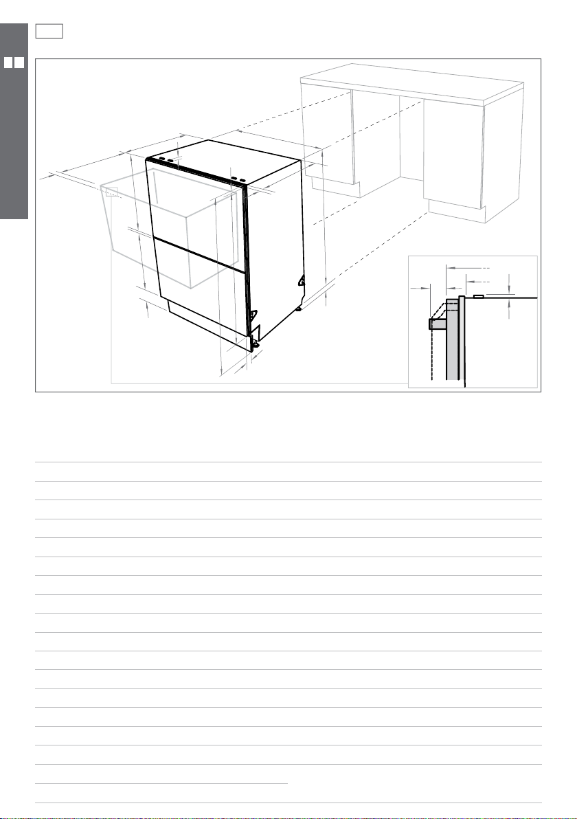
Product dimensions
Installation diagrams for illustration purposes only
C
D
N
I
DOUBLE MODELS
K
L
M
Product dimensions (mm)
overall height* of product
A
overall width of product
B
overall depth of product (excl. curvature/handle)
C
depth of drawer (open) (excl. curvature/handle)
D
height* of chassis
E
height range of levelling feet
F
depth of chassis
G
depth of drawer front panel (excl. curvature/handle)
H
depth of curvature or handle
I
depth of kickstrip
J
height of upper drawer front
K
height of lower drawer front
L
height of kickstrip (adjustable)
M
height of installation tab slots (on top of chassis)
N
height of drawer fronts
O
height* of top of upper drawer to top of chassis
P
* Chassis heights include tab slots
** Designer handle - 41 mm, Curved handle - 36 mm
B
P
G
H
E
C
G
O
A
F
I
N
J
Pre nished
DD605
LCD
819.5 - 879.5 819.5 - 879.5 819.5 - 879.5
595 595 595
570 570 570
520 520 520
809 809 809
60 60 60
552 552 552
18 18 18
30 ** n/a
50 - 65 50 - 65 67 - 127***
394 398 398 min
312.5 311.5 311.5 min
70 - 120 70 - 120 70 - 120
22 2
719.5 717.5 717.5 min
7 2 n/a
*** Pre nished 50-65 mm; Integrated 67 mm less the Kickstrip
Panel thickness (Minimum Panel thickness using the supplied
screws is 9 mm).
Flat door
DD605
Pre nished
Integrated
DD605
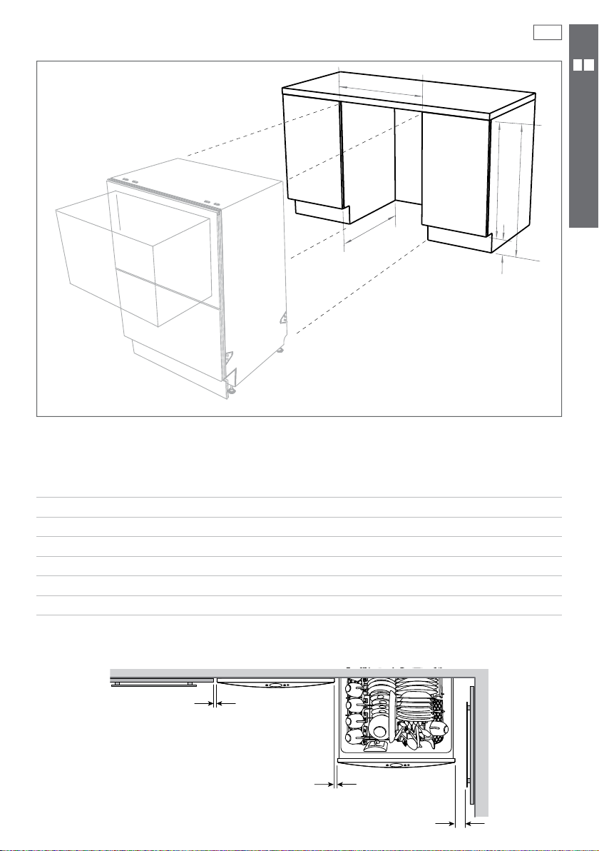
Cabinetry dimensions
Installation diagrams for illustration purposes only
B
C
3
D
A
DOUBLE MODELS
E
Cabinetry dimensions (mm)
inside height of cavity
A
inside width of cavity
B
inside depth of cavity (inside)
C
height of adjacent cabinetry
D
height of kickstrip
E
Minimum clearances (mm)
2.5 mm
2.5 mm
Pre nished
DD605
LCD
820 - 882.5 820 - 882.5 820 - 882.5
600 600 600
580 580 580
720 720 720
70 - 120 70 - 120 70 - 120
Flat door
DD605
Pre nished
DD605
13 mm
Integrated
4
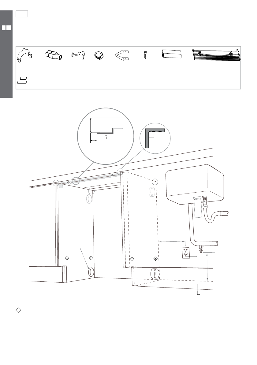
Cavity preparation
Parts supplied
Drain hose
support (1)
DOUBLE MODELS
If the Drain hose(s) supplied are not long enough to reach your services, you must use a Drain Hose Extension Kit
P/N 525798 which will extend the drain hose(s) by 3.6m. The kit is available from the nearest Fisher & Paykel
Authorized Service Agent or www.fisherpaykel.com. DO NOT extend beyond this limit.
Note: Services can be located
either side of DishDrawer®.
Drain hose
joiner (1)
Hexagonal sockets (2)
(Long & Short)
Wire clip (2)
min. ø50 mm
Clamp (1)
10 mm
Install
tabs (2)
Moisture
protection
tape must
be applied.
Phillips
16 mm
screws (9)
Moisture
protection
tape (1)
(to prevent moisture
damage)
o
90
max. 450 mm
Prefinished toe kick (1)
White or Black
min. 200 mm
*
These marks indicate mounting tab screw locations
Preferred position. If adequate clearance, services hole can be higher to clear toe kick space.
*
If hole is higher, ensure drain hose(s) are routed straight into the waste connection.
*
220-240 VAC
min. 9 A
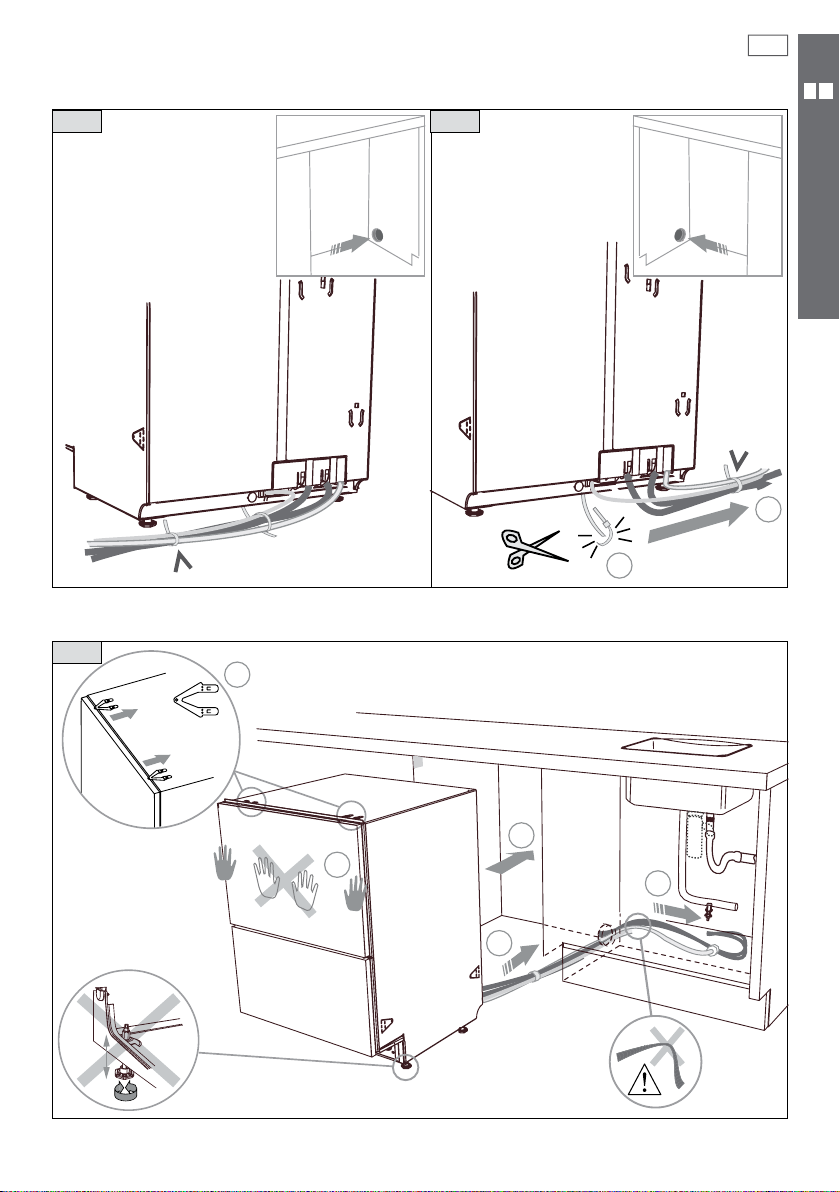
Route the hoses and move into the cavity
5
1a
1b
DOUBLE MODELS
2
Tie together to avoid kinking
2
optional
optional
If top two tabs are being
used, ensure they’re securely
2
fitted before sliding product
into cavity.
1
Loosen feet first, but
do not fully extend
until product is in cavity.
3
3
1
1
Ensure hoses and cord
are not kinked or twisted.
6
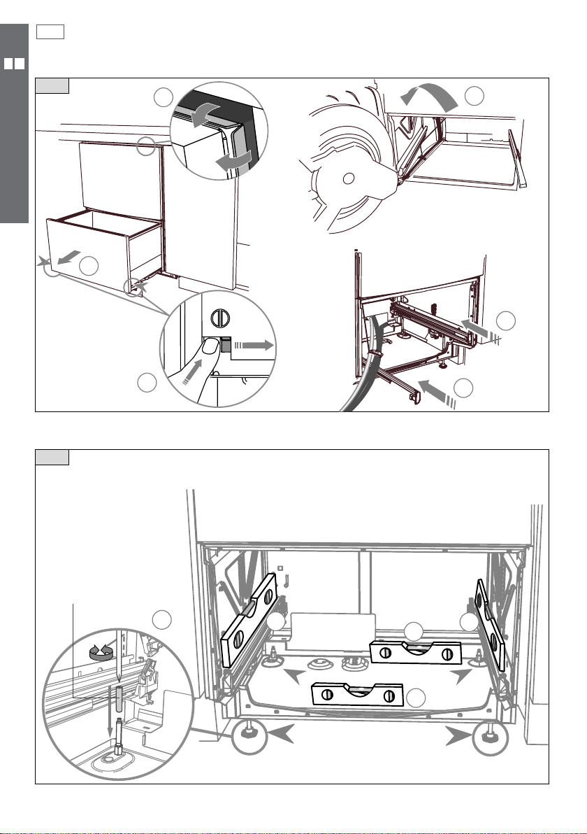
Removing the tub and levelling the product
3
DOUBLE MODELS
2
4
1
Ensure the tub is removed and
then rotated counter-clockwise
to prevent kinked hoses.
30 mm
3
Ensure product is level. Using the most appropriate length
Hexagonal socket supplied, and a screwdriver, fully extend
levelling feet up to required distance.
4
5
5
Hexagonal socket
1
2
4
3
5
x 4
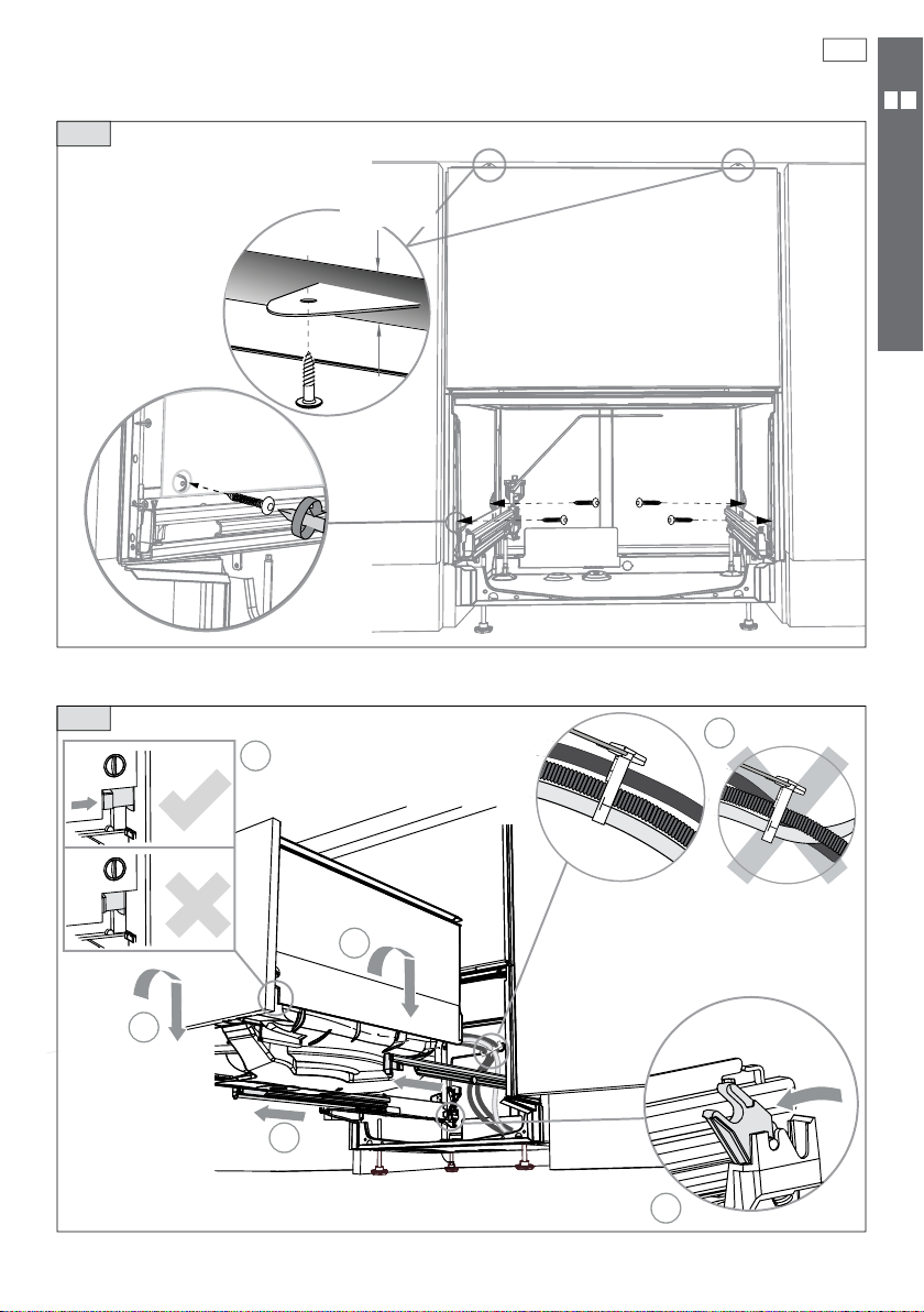
Securing the product and re tting the tub
5
The mounting tabs
are in pairs, one on
each side of the
product. At least two
sets of tab pairs must
be used.
A and B tab pairs
OR B and C tab pairs
or all three pairs.
Ensure the sound
insulation is
repositioned
correctly.
optional
C
C
7
DOUBLE MODELS
6
4
Ensure the tub is
now rotated
clockwise back.
Ensure the tub clips on
both sides are reset.
5
4
1
BB
A
A
3
Before refitting the tub,
ensure the hoses are not
twisted and the latches at
the rear of each drawer
runner are facing forward.
2
 Loading...