

Page 1
MODELS
DD603
DD603I
DS603
DS603 I
DD603M
DS603M
DD603H
DD603IH
DS603H
DS603IH
DD603HM
DD603HM
599082
Page 2

Page 3

Manual 599082 March 2004
Changes:
Aug 03: Addition of info on Dry Enhancement Mode – refer section 4.1.8, page 20, plus many minor alterations
throughout manual.
Mar 04: Dimensions and Specifications updated p 9, 10.
Fisher & Paykel Appliances Inc
27 Hubble, Irvine, California,
CA92618,
USA
Ph: 949 790 8900
Fax: 949 790 8911
Fisher & Paykel Customer Services
PO Box 798
19 Enterprise St
Cleveland, Queensland 4163
AUSTRALIA
Tel: (07) 3826 9122
Fax: (07) 3826 9164
Email: parts@fp.com.au
A.C.N 003 335 171
Fisher & Paykel Appliances
150 Ubi Avenue 4
Sunlight Building #02-00
SINGAPORE 408825
Tel: 6547 0100
Fax: 6547 0123
COPYRIGHT Ó FISHER & PAYKEL LTD 2004
Fisher & Paykel Appliances Ltd
Whiteware Spare Parts
PO Box 58-732, Greenmount
80 Springs Rd, East Tamaki
NEW ZEALAND
Tel: (09) 272 0261
Fax: (09) 272 0219
Email: parts@fp.co.nz
Fisher & Paykel Appliances
Helpline
209 Purley Way, Croydon
Surrey, CT9 4RY
GREAT BRITAIN
Tel: 0845 600 1934
Fisher & Paykel Appliances Ltd
International Division
PO Box 58-732, Greenmount
80 Springs Rd, East Tamaki
NEW ZEALAND
Tel: (09) 2730660
Fax: (09) 2730580
Email: parts.international@fp.co.nz
Fisher & Paykel Helpline
C/o C&F Quadrant
Unit L
40 Cherry Orchard Industrial Estate,
Dublin 10
IRELAND
Tel: 01 630 5757
Fax: 01 630 5706
Page 4

C O N T E N T S
1.0 SERVICE REQUIREMENTS ........................................................................................................... 7
1.1 HEALTH & SAFETY ........................................................................................................................7
1.1.1 E
1.1.2 E
1.1.3 G
1.1.4 I
1.1.5 W
1.1.6 I
1.1.7 S
1.1.8 S
1.1.9 D
1.2 S
1.2.1 S
1.2.2 F
2.0 DIMENSIONS & SPECIFICATIONS ................................................................................................ 9
LECTRICAL SAFETY...............................................................................................................7
LECTROSTATIC DISCHARGE................................................................................................... 7
OOD WORKING PRACTICES................................................................................................... 7
SOLATE WATER SUPPLY.........................................................................................................7
ATER LEAK CHECK...............................................................................................................7
NSULATION TEST ................................................................................................................... 7
OLVENT AND EXCESSIVE HEAT DAMAGE ................................................................................8
HEET METAL EDGES .............................................................................................................8
IAGNOSTICS .........................................................................................................................8
PECIALISED TOOLS...................................................................................................................... 8
TATIC STRAP:.......................................................................................................................8
ISHER & PAYKEL SMART TOOL ..............................................................................................8
2.1 DIMENSIONS..................................................................................................................................9
2.2 S
2.2.1 E
2.2.2 C
PECIFICATIONS ............................................................................................................................ 9
LECTRICAL ........................................................................................................................... 9
OMPONENTS ........................................................................................................................ 9
3.0 TECHNICAL OVERVIEW ............................................................................................................. 11
3.1 CHASSIS ..................................................................................................................................... 11
3.2 D
3.3 E
3.3.1 T
3.3.2 T
3.4 M
3.4.1 R
3.4.2 S
3.5 W
3.6 L
3.6.1 L
3.6.2 W
3.6.3 D
3.7 T
3.8 F
3.8.1 W
3.8.2 D
3.8.3 A
3.9 H
3.9.1 T
3.9.2 H
3.9.3 M
3.9.4 O
RAWER FRONTS ........................................................................................................................11
LECTRONICS..............................................................................................................................11
UB HOME SENSOR ..............................................................................................................11
OUCH SWITCHES ................................................................................................................ 12
OTOR .......................................................................................................................................12
OTOR.................................................................................................................................12
PRAY ARM..........................................................................................................................12
IRING COVER............................................................................................................................ 12
ID SYSTEM.................................................................................................................................12
ID OPERATION ....................................................................................................................12
HEN ACTIVATED................................................................................................................. 12
URING A POWER FAILURE ...................................................................................................12
UB.............................................................................................................................................12
ILLING ....................................................................................................................................... 13
ATER INLET ....................................................................................................................... 13
ISPENSING DETERGENT AND RINSE-AID...............................................................................13
MOUNT OF WATER ..............................................................................................................13
EATING .....................................................................................................................................13
HE ELEMENT.......................................................................................................................13
EATING THE WATER............................................................................................................ 13
AINTAINING THE TEMPERATURE ..........................................................................................13
VERHEAT PROTECTION .......................................................................................................14
- 4 -
Page 5

3.10 LOCKRING NUT.......................................................................................................................... 14
3.11 D
3.12 F
3.12.1 T
3.12.2 R
3.13 D
3.14 W
RAIN CYCLE ............................................................................................................................14
ILTER PLATE ...........................................................................................................................14
HE FILTER SYSTEM ...........................................................................................................14
EMOVING AND CLEANING THE FILTER PLATE......................................................................14
RYING CYCLE..........................................................................................................................14
ATER SOFTENER (WHERE FITTED) ...........................................................................................15
4.0 OPTION ADJUSTMENT MODE .................................................................................................... 16
4.1 HOW TO CHANGE SETUP OPTIONS ...............................................................................................16
4.1.1 R
INSE AID / WATER SUPPLY HARDNESS / AUTO POWER / END OF CYCLE BEEPS / CLOSED
DRAWER OPTION / CLEAN/DIRTY DISH SYMBOL /DRY ENHANCEMENT OPTION ............................................16
4.1.2 R
4.1.3 W
4.1.4 A
4.1.5 E
4.1.6 C
4.1.7 C
4.1.8 D
4.1.9 O
INSE AID SETUP (RA).......................................................................................................... 16
ATER SUPPLY HARDNESS SETUP (HD) ................................................................................ 16
UTO POWER OPTION (AP)...................................................................................................17
ND OF CYCLE BEEPS (EC) ..................................................................................................17
LOSED DRAWER OPTION (LD) .............................................................................................17
LEAN/DIRTY DISH SYMBOL (DS)...........................................................................................17
RY ENHANCEMENT OPTION (LH) ........................................................................................17
PTION ADJUSTMENT QUICK REFERENCE CHARTS ...............................................................18
5.0 DIAGNOSTICS .............................................................................................................................. 20
5.1 DISHDRAWER DIAGNOSTICS ........................................................................................................20
5.1.1 D
5.1.2 O
5.1.3 C
5.1.4 H
5.1.5 F
5.1.6 C
5.1.7 T
5.1.8 S
ISPLAY / DOWNLOAD MODE ................................................................................................20
PTICAL LED DOWNLOAD / FAULT DISPLAY ..........................................................................20
LEARING FAULT LOGS......................................................................................................... 20
ARDWARE OUTPUT DIAGNOSTIC TEST MODE....................................................................... 20
AST TEST CYCLE ................................................................................................................21
ONTINUOUS CYCLE TEST MODE .......................................................................................... 21
EMPERATURE & VOLTAGE DISPLAY MODE ...........................................................................22
HOW OFF / SHOWROOM WASH MODE .................................................................................22
6.0 DIAGNOSTICS QUICK REFERENCE CHARTS ........................................................................... 24
6.1 FAULT DISPLAY/DOWNLOAD MODE:- ...........................................................................................24
6.2 H
6.3 F
6.4 C
6.5 T
ARDWARE OUTPUT TEST MODE:-...............................................................................................24
AST TEST CYCLE:-.....................................................................................................................25
ONTINUOUS CYCLE:- .................................................................................................................25
EMPERATURE & VOLTAGE DISPLAY MODE:-............................................................................... 25
7.0 FAULT CODES ............................................................................................................................. 26
7.1 FAULT CODE DESCRIPTION CHART ..............................................................................................27
7.2 F
7.3 P
7.4 P
AULT CODE PROBLEM SOLVING CHARTS ...................................................................................28
OOR DRY PERFORMANCE ..........................................................................................................32
OOR WASH PERFORMANCE .......................................................................................................32
8.0 WIRING DIAGRAM ....................................................................................................................... 35
- 5 -
Page 6

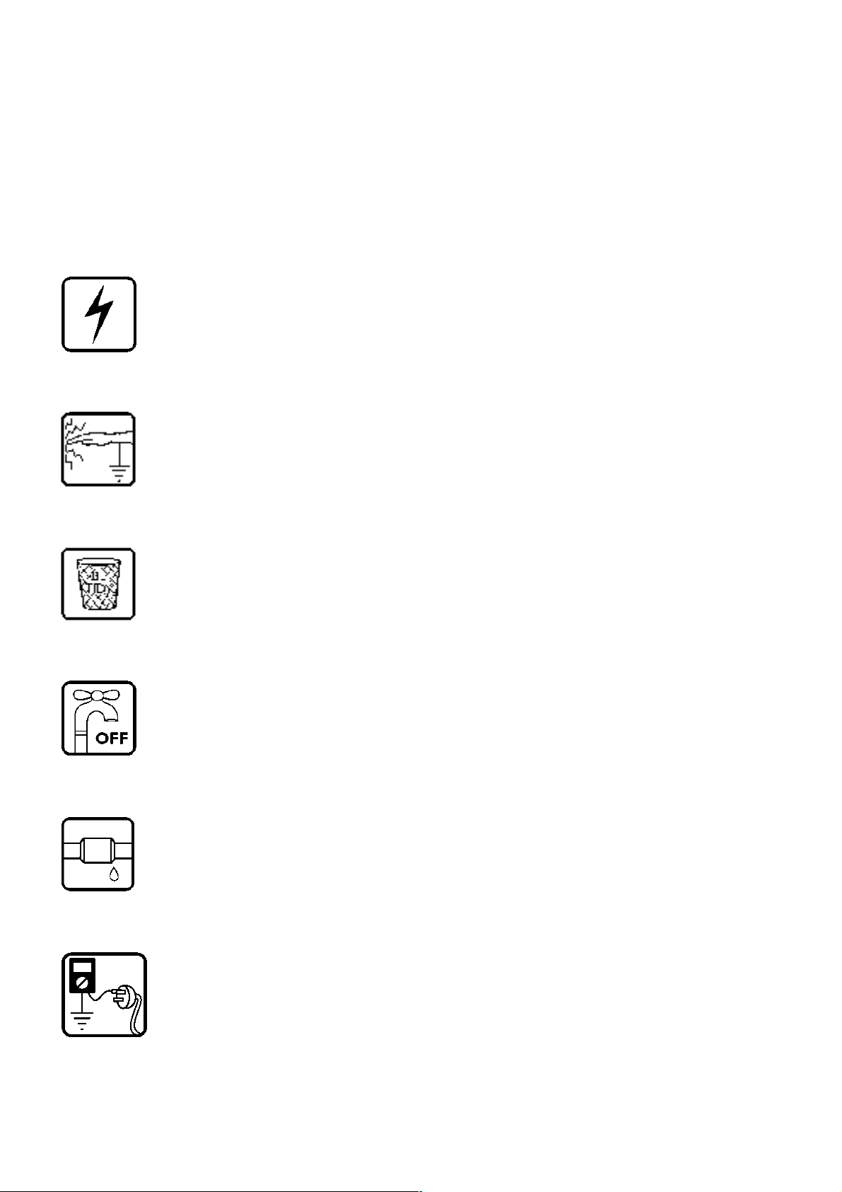
9.0 SERVICE PROCEDURES ............................................................................................................. 36
9.1 DRAWER FRONT REMOVAL ..........................................................................................................36
9.2 T
9.3 D
9.4 D
9.5 D
9.6 E
9.7 F
9.8 R
9.9 W
9.10 T
9.11 R
9.12 L
9.13 L
9.14 Y
9.15 L
9.16 S
9.17 C
9.18 W
9.19 F
9.21 T
9.22 L
9.23 F
9.24 W
UB REMOVAL.............................................................................................................................36
RAWER AND LCD DISPLAY REMOVAL ........................................................................................37
RYING FAN REMOVAL ................................................................................................................ 37
ETERGENT DISPENSER ..............................................................................................................38
LECTRONIC CONTROLLER..........................................................................................................38
ILTER PLATE REMOVAL .............................................................................................................39
OTOR ASSEMBLY REMOVAL ......................................................................................................39
IRING COVER REMOVAL............................................................................................................39
UB DISCONNECTION.................................................................................................................40
OTOR SENSOR REMOVAL ........................................................................................................40
OCKING RING, ELEMENT PLATE AND MOTOR ASSEMBLY REMOVAL ..........................................41
ID REMOVAL............................................................................................................................42
OKE REMOVAL ........................................................................................................................42
ID ACTUATOR REMOVAL ..........................................................................................................43
LIDE RAIL REPLACEMENT ........................................................................................................44
HASSIS CIRCUIT BOARD / FLOOD SENSOR REMOVAL ............................................................... 44
ATER VALVE REMOVAL........................................................................................................... 45
ILL HOSE, DRAIN HOSE, WIRING HARNESS REPLACEMENT.......................................................45
OE KICK REMOVAL ..................................................................................................................46
OWER TUB COWLING...............................................................................................................46
RONT TRIM REPLACEMENT....................................................................................................... 47
ATER SOFTENER ....................................................................................................................47
- 6 -
Page 7
March 2004 Manual 599082
1.0 SERVICE REQUIREMENTS
1.1 Health & Safety
Note: When servicing the DishDrawer, Health and Safety issues must be considered at all
times. Specific safety issues are listed below with their appropriate icon. These are illustrated
throughout the service information to remind service people of the Health and Safety issues.
1.1.1 Electrical Safety
Ensure the mains power has been disconnected before servicing the DishDrawer. If the mains
supply is required to be on to service the DishDrawer, make sure it is turned off when removing
any electrical component or connection to avoid electrical shock.
1.1.2 Electrostatic Discharge
An anti-static strap is to be used as electrical static discharge (ESD) protection when servicing
electronic components.
1.1.3 Good Working Practices
Ensure the work area is in a tidy and orderly condition at all times so as not to cause a hazard
while service work is being completed. Always clean and tidy the DishDrawer and work area after
service is completed.
1.1.4 Isolate Water Supply
Turn off the water connection tap before servicing.
1.1.5 Water Leak Check
Check for water leaks as part of the testing after the service has been completed.
1.1.6 Insulation Test
Megger test to check insulation.
Warning: Short together the phase and neutral pins on the plug so as not to damage any
electronic circuitry.
- 7 -
Page 8

March 2004 Manual 599082
1.1.7 Solvent and Excessive Heat Damage
Plastic surfaces can be damaged by solvents and excessive heat.
1.1.8 Sheet Metal Edges
When working around cut sheet metal edges use appropriate gloves or protection to eliminate
the chance of receiving a laceration.
1.1.9 Diagnostics
While in diagnostics some safety devices are bypassed.
Ensure you do not run components unattended. They may overheat, flood, burnout or cause
water damage.
1.2 Specialised Tools
For servicing this product Specialised tools are required.
1.2.1 Static Strap:
To be used as ESD protection when replacing or handling electronic components.
1.2.2 Fisher & Paykel Smart Tool
Handheld palm computer supplied in protective case with F&P diagnostics software and service information
loaded:
P/N 813141 (includes light pen P/N 425930).
- 8 -
Page 9

March 2004 Manual 599082
2.0 DIMENSIONS & SPECIFICATIONS
2.1 Dimensions
Product Size
(mm)
Height (double) 819.5-879.5 32
Height (single) 409mm 16
Width 595mm 23
Depth 570mm 22
Drawer Open (inc cab) 1080mm 42
2.2 Specifications
2.2.1 Electrical
Market Voltage Frequency Current double/single
NZ/AUS/UK/EU 230-240 V AC 50 Hz 10 A / 5 A max
USA 110-120 V AC 60 Hz 12.5 A / 6.5 A max
JAP 90-110 V AC 50/60 Hz 11.6 A / 5.8 A max
KOREA 220 - 240 60 HZ - / 4.5 A max.
Product Size
(inches)
1/4
inch – 34
3/32
inch 412mm 16
7/16
inch 600mm 23
7/16
inch 580mm 22
1/2
inch
5/8
inch 822.5-882.5mm 32
Minimum Cavity
Size
Minimum
Cavity Size
3/8
inch
7/32
inch
5/8
inch
7/8
inch
2.2.2 Components
Component Part Number Specifications
Water Inlet Valve Ph3.5
Ph3.5
Ph3
Ph3
Dispenser
P/N 526850 Double 2.5litre
P/N 526851 Single 2.5 litre
P/N 525113 Double 5 litre
P/N 525842 Single 5 litre
24V DC
70+/- 5 Ohms per coil
2.5Lt/min (0.65 USgal/min)
5 litre/min (1.3 US gal/min)
P/N 526860 24V DC per coil
70+/- 5 Ohms per coil
Rinse Aid capacity
Mains Filter Board
P/N 525958P
50mls (approx. 25 washes)
240V AC
(NZ/AUS/UK/EU/KR)
Mains Filter Board (USA/JAP)
Motor
Drain Direction
Wash Direction
P/N 525959P
5 litres / min.
120V AC
80V DC 3 Phase
4200 RPM
2600 RPM
Stator P/N 526530 8.0 +/- 5 Ohms (per winding), 16
ohms phase to phase from controller
connector
- 9 -
Page 10

March 2004 Manual 599082
Component Part Number Specifications
Heater Plate (NZ/AUS/UK/EU/KR)
Heater Track
Power Supply Resistor
Heater Plate (USA)
Heater Track
Power Supply Resistor
Heater Plate (JAP)
Heater Track
Power Supply Resistor
Temperature Sensor On Heater Plate 962 Ohms @ 200C (680F)
Fuseable Link On Heater plate 268 – 302oC (514 – 576oF)
Inlet Hose (NZ/AU/ /KR)
Inlet Hose (WP/EU/DK/GB)
Inlet Hose (USA)
Inlet Hose (JAP)
Drain Hose
Drain Hose (Lower)
Drain Hose (Upper)
Drying Fan P/N 526752 3.4K Ohms
Diverter Valve Softener Assy P/N 526416 24V DC Coil
Brine Pump Assy P/N 526418 24V DC Coil
Water Softener 500 grams Salt Capacity
Lid Actuator
Top left
Top right
Bottom left
Bottom right
Hall Sensor P/N 526340 4.13, and 3.43 M ohms
P/N 527701 240V AC
60 Ohms +/- 3 Ohms
125 Ohms +/- 5 Ohms
P/N 527702 120V AC
26 Ohms +/- 2.5 Ohms
30 Ohms +/- 5 Ohms
P/N 527703 110V AC
20 Ohms +/- 1.5 Ohms
20 Ohms +/- 2 Ohms
1000 Ohms @ 300C (860F)
1202Ohms @ 600C (1400F)
P/N 521349
P/N 527021
P/N 525970
P/N 526809
P/N 525966
P/N 525967
P/N 526275
P/N 526371
P/N 526469
P/N 526470
1.7m (66 inches)
1000Kpa / 145 P.S.I.
2.0m (78 inches) from rear of
cabinet
2.5m (98 inches) bottom tub
2.9m (114 inches) top tub
70 +/- 5 Ohms Coil
70 +/- 5 Ohms Coil
approx 14 regenerations
290+/- 10ml Resin
24 V DC
measured +ve in centre, -ve to
outside
- 10 -
Page 11

March 2004 Manual 599082
3.0 TECHNICAL OVERVIEW
3.1 Chassis
The DishDrawer chassis is one complete assembly composed of 5 steel metal components locked together by a
proprietry riveting process. The chassis exterior is made of a lacquered electrogalvanised material called
Galvoclean.
Unlike most other dishwashers, the chassis assembly is a load carrying structure designed to impart stiffness to the
product and to ensure deflection is minimised.
The feet of the Double cabinet are assembled into the chassis by means of four steel inserts which are clinched in
place to form a permanent threaded connection.
The tub extends 520mm (2015/32”) out of the cabinet by travelling along two rigidly attached slides on either side of
the tub.
3.2 Drawer Fronts
Prefinished drawer fronts are formed from a painted, brushed or Iridium finish stainless steel blank. The drawer
fronts are attached to the tub by means of formed hooks and two pins which are inserted through either side of the
tub.
On the integrated model, the front panel supplied on each drawer is the mounting panel for the joinery finished
drawer front. The joinery finished drawer front is supplied by the customer.
3.3 Electronics
In the DD603/ DS603 (Phase 3) electronic controller the functions of controlling the motor as well as controlling the
user interface console have been combined into a single 16-bit Micro Controller on the main printed circuit board.
This Micro controller also controls a transformerless 85w switchmode power supply. This power supply utilises a
large dropping resistor on the heater plate in conjunction with phase control of the mains voltage in order to produce
a variable voltage rail. From this the controller can supply voltages from 5V to 85V to the various components in the
DishDrawer.
NOTE:- With power supplies of this nature all components regardless of supply voltage should be treated as live to
earth. i.e = supply voltage.
The user interface comprises a printed circuit board for front controls and a touch switch panel for internal controls.
The electronics can connect to a computer service tool via an optical light pen for fault finding and product
information.
The element is switched by one single pole relay. Overheat protection is effected by a short length of solder in series
with the dropper resistor track on the heater plate. In an overheat situation this solder melts causing the power
supply to go open circuit.
3.3.1 Tub Home Sensor
A tub home sensor is used to determine when the tub is closed and it is safe to start a cycle. The tub home sensor
consists of an inferred LED (sender) and an inferred transistor (receiver) mounted on the circuit board in the
controller. Inferred light is transmitted from the LED through an optical light pipe to the right hand side of the tub. The
inferred receiving transistor also has an optical light pipe leading from it out to the side of the tub. When the tub is
closed the two light pipes are optically connected via a prism mounted in the trim on the side of the chassis.
- 11 -
Page 12

March 2004 Manual 599082
3.3.2 Touch Switches
Two touch switches are used on the secondary control panel one to select the required wash cycle and one to turn
the Eco option on or off. They are capacitive touch switches and are supplied with an analogue signal from the
controller that will change in the presence of an earthed mass (i.e. customer’s finger).
3.4 Motor
The motor is a fully electronically controlled 80V, 60w, 3 phase, 6 pole brushless DC motor, running on wash at
between 2300-2850rpm depending on the cycle selected and at approximately 4200 rpm on Drain.
3.4.1 Rotor
The rotor is a four pole permanent magnet rotor with a graphite bearing at each end of the vertical shaft. At the
lower end of the rotor shaft is the drain impellor and at the upper end is the wash impellor.
3.4.2 Spray Arm
The spray arm is shaped for most efficient waterflow. The holes are positioned for best penetration into the wash
load, with the water jets angled to ensure the spray arm rotates at the most efficient speed. There is a flap valve
moulded into the top of the spray arm. This part lets air through the spray arm when the DishDrawer is filling with
water. The DishDrawer fill levels are more consistent with the flap valve system.
3.5 Wiring Cover
The wiring cover protects the customer from all electrical components in the motor area underneath the tub. All
electrical components regardless of voltage should be treated as live with respect to earth. It also serves to protect
the motor assembly, drain and fill hoses from damage when opening and closing drawers. The wiring cover acts as
a cosmetic part of the product.
3.6 Lid System
3.6.1 Lid Operation
The lid is a single piece of polymer plastic with a static seal co-injection moulded into it. Each side of the lid is clipped
into a yoke which is in turn connected to a worm drive lid actuator assembly containing a small brushed DC 24V
motor.
3.6.2 When Activated
At the beginning of each wash cycle, both motors are powered for approximately 10 seconds, which pulls the lid
down onto the tub in approx 5 seconds. The lid remains down for the duration of the cycle and is only lifted when the
DishDrawer beeps to signal the end of the cycle or if the customer pauses it to gain access to the tub.
3.6.3 During a Power Failure
If power to the DishDrawer fails with the lid down you can still force the tub open manually if access is required. It is
very difficult however to close the tub again without lifting the lid. The lid can be wound up manually with the tub fully
removed. Failure to raise the lid before closing the Drawer could result in the lid seal being damaged.
3.7 Tub
The tub is the main cavity where all the wash activity occurs. The tub is a polymer plastic receptacle which has a
wash pump and spray arm at the base. The tub also has guide vanes around its walls which direct falling water from
the wash cycle in a clockwise direction around the filter plate. This clears the filter plate of food particles into the
sump where they can be trapped or pumped out during the drain cycle.
- 12 -
Page 13

March 2004 Manual 599082
3.8 Filling
3.8.1 Water Inlet
The tub of the DishDrawer fills by a single water inlet hose, hot water connection for USA and Japanese products
and cold water connection recommended for the Australasian/UK/ Europe products. From the connection to the
water supply in the kitchen, the inlet hose enters the cabinet of the dishwasher at the base, onto a dual water valve.
Each tub is supplied water independently via one of the dual valve coils and a fill hose that runs through a
customised link assembly at the back of each tub and travels along the base of the tub under the wiring cover to the
front. At the front of the tub, the fill hose connects to the detergent dispenser which allows water to enter the tub,
firstly through the pre rinse section of the dispenser for the pre rinse cycle and secondly through the main wash
section for all other cycles.
In a product fitted with a water softener, water is directed through the softener before entering the dispenser.
3.8.2 Dispensing Detergent and Rinse-aid
The dispenser is mounted in the front wall of the wash tub.
The detergent dispenser consists of two detergent chambers, one for pre wash and the other for the main wash.
The detergent dispenser door is opened manually for detergent loading and then manually closed ready for the
detergent to be transported to the wash tub by the inlet water. To enable each detergent chamber to be dispensed
separately, an inlet water diverter valve controlled by the electronics is required.
Additionally a positive displacement pump unit and storage tank are incorporated within the dispenser to supply rinse
aid. The rinse aid dispensed volume can be adjusted by the customer in option adjustment mode. A glowing red
light on the tank filler cap indicates an empty rinse aid tank.
3.8.3 Amount of Water
The tub fills with approximately 2.5 litres / 0.8 US gallons of water, approximately level with the base of the spray
arm. Once this level is reached, the wash pump (which has sensed the fill via the electronics) becomes primed and
pumps the water through the spray arm which will then rotate. The load on the wash pump is constantly monitored
throughout the wash cycle and the water level adjusted if necessary.
3.9 Heating
3.9.1 The Element
The heater plate is an element consisting of a porcelain enamelled steel plate with a thick film resistive circuit printed
onto the dry side. As well as the heating circuit a large dropping resistor is also printed onto the heater plate which
forms part of the controllers power supply. The element is clamped in place by a lockring nut and supports the motor
at the base of the tub.
3.9.2 Heating the Water
The heater plate lies beneath the filter plate. A flow through water heating system is created during the wash cycle
by allowing water to flow through the filter plate, over the surface of the element and into the wash pump.
3.9.3 Maintaining the Temperature
Attached to the element is a sub printed circuit board with a temperature sensitive thermistor. This connects by
means of a RAST 2.5 connector system to the wiring harness of the element. Sensor components are
unserviceable and if they fail a new heater plate is required.
- 13 -
Page 14

March 2004 Manual 599082
3.9.4 Overheat Protection
The heater plate is only activated during the wash cycles. It is not used for drying. The temperature is maintained
by the thermistor. If a failure occurs with the electronic control of the heater plate, overheat protection is effected by
a thermal fuse on the heater plate itself.
The thermal fuse consists of a short length of solder in series with the dropper resistor track which will melt at a
relatively low temperature, 268 – 302oC (514 – 576oF) causing the controllers power supply to go open circuit
disconnecting power to the element.
3.10 Lockring Nut
The lockring nut holds the heater plate into the base of the tub and motor housing assembly to form a watertight
seal. It does this by compressing two large ‘O’ rings between the heater plate and tub and between the heater plate
and the motor assembly.
It has clips which hold the drain hose, fill hoses and the wiring loom in place.
Another function of the lockring nut is to support the wiring cover with three clips.
3.11 Drain Cycle
The drain pump is a self priming centrifugal pump which only pumps when the motor is rotating in the drain direction
(anti-clockwise). It has a five bladed impellor pushed into a spline on the end of the rotor shaft.
The drain pump housing, which incorporates an inlet and outlet pipe, is welded to the motor housing, hence
captivating the motor.
The inlet pipe plugs straight into the sump and is sealed there by a small ‘O’ ring.
The outlet pipe has a non return flap valve to prevent soiled water returning to the tub.
The drain hose is an extruded blow mould hose which is routed over the link assembly and exits out of the base of
the product and is connected to a domestic drain.
The drain speed during the wash program is approx. 4200 rpm. In hardware output diagnostics test mode it is
approx. 5000 rpm. This can account for draining OK in diagnostics but not during normal operation.
3.12 Filter Plate
The filter plate is a stainless steel disk which lies below the dish rack and spray arm and completely encompasses
the base of the tub.
3.12.1 The Filter System
The tub is designed with vanes which swirl the water around and over the filter plate. At the front of the tub, located
as part of the filter plate, is the drain filter. Large soils collect in the drain filter and only smaller soils flow through its
micro mesh filter, eliminating re-depositing of soil during the wash. The drain filter should be regularly checked and
cleaned.
3.12.2 Removing and Cleaning the Filter Plate
The drain filter can be emptied with the dish rack in place by removing the cutlery basket and opening the plastic
section of the dish rack. The filter plate is removable for cleaning by removing the dish rack and spray arm and
unlocking the lockring nut anti-clockwise.
3.13 Drying Cycle
Immediately after water from the final hot rinse has been drained from the tub, the drying system begins operation.
The drying fan draws air through from the vent in the rear of the tub, where it absorbs water from the dish load. The
moisture laden air is then mixed with a larger quantity of ambient air (from the kitchen), to minimise the amount of
vapour visible when exiting from bottom of the drawer front.
- 14 -
Page 15

March 2004 Manual 599082
The fan runs continuously during the drying cycle and will restart if the tub is opened and closed again. After the
wash program is complete, the lid drives up, and the fan continues to run for 30 minutes, but will not restart if the tub
is opened.
3.14 Water Softener (where fitted)
The Water Softener uses a softening material (resin) to prevent most of the elements that cause hard water from
being present in the wash water. The resin can only treat a limited amount of water before it needs to be
regenerated. Regeneration is achieved by pumping salty water (brine) through the resin, and flushing away the hard
elements to the drain. The process of delivering softened water, and regeneration is controlled by the Electronic
Controller.
Delivering Softened Water:- Supply water arrives from the inlet valve. In the water softener it passes through a
piper interrupter (air break) and a diverter valve. It is then either directed through the resin to the dispenser, or
directly to the dispenser, then into the tub. The electronic controller measures the volume of water treated, and adds
an appropriate amount of non-treated water, to deliver a mix which is at the required hardness according to a predetermined schedule. Water is treated according to its supply hardness. The customer is able to select one of 5
settings in option adjustment mode.
Regeneration:- Regeneration is triggered when the amount of water that has been treated since the last
regeneration nears the capacity of the Water Softener. The quantities treatable for each of the 5 settings of supply
hardness have been predetermined, and are stored in the electronic controller. When triggered, immediately after
filling for the main wash, the brine pump is activated and delivers a volume of salty water into the resin, at an amount
appropriate to the hardness setting. When the wash cycle finishes, the resin is flushed with supply water, and the
by-products of regeneration are delivered into the wash water, and drained with it away to waste. Normal treatment
of incoming water then resumes.
Salt:- the customer is required to fill the salt tank with dishwashing salt from time to time. Salt is used in the water
softener by mixing it with water to produce the salty water (brine) used in regeneration. When the salt level is low, a
salt level detector causes a glowing red light to appear in the salt bung, and a “Salt” symbol appears in the LCD.
When this happens, the customer should remove the salt bung, and using the salt container provided, pour salt into
the salt reservoir until salt can be seen at the opening. The “Salt” symbol on the LCD will disappear and the red light
will not be visible when the salt tank bung is replaced. In areas where the supply water is moderately hard (21 dH –
degrees of hardness, 375ppm – parts per million, Water Softener Setting 3) the salt reservoir will need to be filled
about once a month, and in harder areas more frequently. Delivery of treated water from one fill of the salt reservoir:
240 litres at 30 – 100 ppm from 375 ppm supply water
144 litres at 30 – 100 ppm from 625 ppm supply water
- 15 -
Page 16

March 2004 Manual 599082
4.0 OPTION ADJUSTMENT MODE
4.1 How to Change Setup Options
4.1.1 Rinse Aid / Water Supply Hardness / Auto Power / End of Cycle Beeps / Closed Drawer Option /
Clean/Dirty Dish Symbol /Dry Enhancement Option
To enter this setup mode, press Power, then hold the Eco touch switch and KeyLock button simultaneously for 5
seconds ensuring that Eco is pushed first. Once the setup mode is entered a beep is emitted and the LCD displays
the letters rA. By pushing the Start/Pause button you can scroll through and change the following options:Rinse Aid Setup (rA)
Water Supply Hardness Setup (hd)
Auto Power Option (AP)
End of Cycle Beeps (EC)
Closed Drawer Option (Ld).
Clean/Dirty Dish Symbol (dS)
Dry Enhancement Option (LH)
Integrated:- On an Integrated DishDrawer, where there is no display, you can still tell which option you have chosen
by using the lights showing on the integrated badge as follows:Rinse Aid Setup (red light above Start/Pause button)
Water Supply Hardness (green light above Start/Pause button)
Auto Power Option (orange light above Start/Pause button)
End of Cycle Beeps (green light above Start/Pause and red light above Keylock) button)
Closed Drawer Option (red light above Start/Pause and Keylock buttons)
Clean/Dirty Dish Symbol (not available on Integrated models)
Dry Enhancement Option (orange light above Start/Pause button, Eco light is red)
Push Power at any time to exit this setup mode.
4.1.2 Rinse Aid Setup (rA)
The current rinse aid setting is shown using the red LED’s on the touch switch panel.
The amount of rinse aid dispensed into a rinse cycle can be varied to suit the level of hardness of the local water
supply. It is adjusted for 1 - 5 dispenser levels
(1 = approx 0.5mls (1/10) teaspoon of rinse aid, 5 = approx. 2.5mls (½) teaspoon of rinse aid).
Push Keylock to advance the rinse aid setting. Once the desired setting is achieved, push Power to exit. The rinse
aid index is stored in EE memory, so even with the power removed, the rinse aid level is retained.
Integrated:- On an Integrated DishDrawer when you turn on or turn off one of the following options it is indicated by
the red wash cycle LEDs on the secondary control panel. If an option is turned on then all the LEDs turn on and if an
option is turned off all the LEDs turn off.
4.1.3 Water Supply Hardness Setup (hd)
The current supply hardness setting is shown using the red LED’s on the touch switch panel. One of 5 settings
should be selected according to the known hardness of the supply water. Each setting is appropriate for the
following water supply hardness:
No. LED Water Softener turned off, continuous bypass of softener
1 150-250 ppm water supply hardness
2 250-350 ppm water supply hardness
3 350-450 ppm water supply hardness
4 450-550 ppm water supply hardness
5 550-625 ppm water supply hardness
- 16 -
Page 17

March 2004 Manual 599082
Push Keylock to advance the Water Softener setting. Once the desired setting has been achieved push Power to
exit.
Selection of a setting affects how the Electronic Controller diverts supply water, how much water is treated, and how
much salt is used in regeneration, in a manner that optimises the performance of the Water Softener.
4.1.4 Auto Power Option (AP)
The automatic power up sequence that occurs when the tub is opened can be turned on or off using the Keylock
button. If the Scrubbing Brush is showing on the LCD then the auto power up sequence will occur when the tub is
Opened. If the Scrubbing Brush is not showing then the DishDrawer will not automatically power up when the tub is
Opened (the customer will need to push the power button each time they wish to use the DishDrawer). Push Power
to exit when the desired setting has been selected.
4.1.5 End of Cycle Beeps (EC)
The six beeps that occur at the end of every cycle can be turned on or off using the Keylock button. If the
Scrubbing Brush is showing on the LCD then the end of cycle beeps are activated. If the Scrubbing Brush is not
showing then the end of cycle beeps are deactivated. Push Power to exit when the desired setting has been
selected.
4.1.6 Closed Drawer Option (Ld)
The Closed Drawer Option can be turned on or off using the Keylock button. If the Scrubbing Brush is showing on
the LCD then the Closed Drawer Option is selected and it will keep the DishDrawer locked at all times by bringing
the lid down. When this mode is selected the customer needs to push the power button to lift the lid whenever they
want to open the drawer. When they close the drawer again the lid comes down automatically after 30 seconds and
locks the tub. If the Scrubbing Brush is not showing then the Closed Drawer Option is deactivated.
4.1.7 Clean/dirty Dish Symbol (dS)
(not available on integrated models)
The Clean/dirty dish symbol can be turned on or off using the keylock button. If the Scrubbing Brush is showing on
the LCD then the Clean/dirty dish option is selected. This means that the end of cycle clean dishes symbol will
remain in the LCD display until the power button is pressed to clear it. If the Scrubbing Brush is not showing then the
Clean/dirty dish symbol will disappear when the drawer is first opened at the end of a cycle (factory setting).
4.1.8 Dry Enhancement Option (LH)
(available in prefinished products from MEM741743, manufactured after 21/5/03,
software vesion 3.2.06
available in integrated models from MKM704522, software version 3.2.07)
Dry Enhancement Option can be turned on or off using the keylock button. If the Scrubbing Brush is showing on the
LCD then the Dry Enhancement Option is selected.
This means the lid will stay down and the drying fan will continue running for 4 hrs after the wash program
completes.
If the customer wishes to open or stop the DishDrawer during this 4 hr period, they can do so by pushing the
POWER or START / PAUSE button. This will reset the feature until the end of the next wash program
- 17 -
Page 18

March 2004 Manual 599082
4.1.9 Option Adjustment Quick Reference Charts
Rinse Aid Setting (rA):-
(alter the amount of rinse aid dispensed)
Press and hold Eco, then Keylock for 5 seconds
rA will be displayed (integrated: Red LED above start/pause button showing)
Press keylock
The rinse aid setting will advance on the secondary control panel LEDs with each press
Press Power
Will exit & save selected setting
Water Softener Supply Hardness Setup(hd) (where fitted):-
(alters the Water Softener setting depending on Water Supply hardness)
Press and hold Eco, then Keylock for 5 seconds
RA will be displayed
Press Start / Pause once
Hd will be displayed (integrate: Green LED above Start / Pause Button showing)
Press Keylock
The Water Softener setting will advance on the Secondary Control Panel LED’s with each press.
Press Power.
Will exit and save selected settings.
Auto Power Option (AP):-
(powers up automatically when the drawer is opened)
Press and hold Eco, then Keylock for 5 seconds
rA will be displayed
Press Start/Pause Twice
AP will be displayed (integrated: Orange LED above start/pause button showing)
Press Keylock
Turns Auto Power on & off. Scrubbing brush or secondary control panel LEDs showing = AP on, Scrubbing brush or
secondary control panel LEDs not showing = AP off
Press Power
Will exit & save selected setting
End of Cycle Beeps (EC):-
(six beeps at the end of every cycle)
Press and hold Eco, then Keylock for 5 seconds
rA will be displayed
Press Start/Pause Three Times
EC will be displayed (integrated: Green LED above start/pause button showing)
Press Keylock
Turns end of cycle beeps on & off. Scrubbing brush or secondary control panel LEDs showing = EC on, Scrubbing
brush or secondary control panel LEDs not showing = EC off
Press Power
Will exit & save selected setting
- 18 -
Page 19

March 2004 Manual 599082
Closed Drawer Option (Ld):-
(lid closes automatically every time the drawer is closed)
Press and hold Eco, then Keylock for 5 seconds
rA will be displayed
Press Start/Pause Four times
Ld will be displayed (integrated: Red LEDs above start/pause & keylock buttons showing)
Press Keylock
Turns closed drawer option on & off. Scrubbing brush or secondary control panel LEDs showing = Ld on, Scrubbing
brush or secondary control panel LEDs not showing = Ld off
Press Power
Will exit & save selected setting
Clean/Dirty Dish Option (dS):-
(clean dishes symbol stays on at end of cycle until cleared by pressing power)
Press and hold Eco, then Keylock for 5 seconds
rA will be displayed
Press Start / Pause Five times
dS will be displayed (not available on integrated models)
Press Keylock
Turns clean/dirty dish option on & off. Scrubbing brush showing = dS on, Scrubbing brush not showing = dS off
Press Power
Will exit & save selected setting
Dry Enhancement Option (LH):-
(lid down and fan run-on for 4 hrs at the end of the cycle)
Press and hold Eco, then Keylock for 5 seconds
rA will be displayed)
Press Start / Pause Six times
LH will be displayed (orange light above start/pause, ECO light is red)
Press keylock
Turns the Dry Enhancement Option on / off. Scrubbing brush symbol on = LH on.
Press Power
Will exit & save selected setting
- 19 -
Page 20

March 2004 Manual 599082
5.0 DIAGNOSTICS
5.1 DishDrawer Diagnostics
DishDrawer Diagnostics can only be entered in Power Off mode, ie. When there is no display on the LCD or the
badge LED’s are off. Diagnostics is entered by holding the Keylock and Start/Pause buttons simultaneously for 5
seconds. Ensure that Keylock is pushed first.
There are currently four levels of diagnostics. To move to the next level push Power. To enter a level push
Start/Pause. Once a level has been entered, pushing Power will exit diagnostics completely. If no level is entered
then the display will cycle through the four levels and exit after the last. On entering diagnostic mode the first level is
the Display/Download Mode.
5.1.1 Display / Download Mode
In this mode all LED’s and LCD segments (except keylock) are illuminated.
5.1.2 Optical LED Download / Fault Display
An optical data download is available here to download all EE data to a PC or Palm PC via the lower tub-home
sensor light pipe. Hold the reader pen over the lower tub-home sensor light pipe and press Start/Pause to initiate
the download. A short beep indicates the start and finish of download.
In products manufactured before MEM741743, 21/5/03, the last two faults are displayed on the LCD (secondary
control panel LEDs for integrated models) during the optical download, the Current Fault code is displayed first
followed by the Previous Fault Code. To read the Fault Code on the secondary display for integrated and
prefinished products after MEM741743, refer to Section 7.1 on Fault Codes.
5.1.3 Clearing Fault Logs
To Clear the current Fault press the Keylock button until a beep is sounded. This action moves the Current Fault
into the Previous Fault while clearing the Current Fault. To Clear the Previous Fault press Keylock once more until
the beep is sounded.
Warning: Once a fault has been cleared, it is permanently removed from memory and cannot be recovered.
Press Power to advance to the next level.
5.1.4 Hardware Output Diagnostic Test Mode
This level tests all the hardware outputs and inputs. The LCD display shows ‘HO’.
Press Power to skip hardware diagnostics and advance to the next level.
Press Start/Pause to enter hardware diagnostics.
Once hardware diagnostics has been entered letters in the LCD display indicate the current hardware output being
tested and for integrated models the LEDs on the touch switch panel, using binary encoding, as shown in the table
on the next page.
Different combinations of outputs can be switched on or off together but the controller will prevent higher current
drawing components such as the wash pump and the lid motors being turned on together.
Press Start/Pause to advance to the next hardware output.
Press Keylock to turn the currently displayed output On or Off. If the scrubbing brush symbol (green LED above
start/pause button on integrated models) is displayed then that output has been switched on, and if it is not
displayed then that output is off.
- 20 -
Page 21

March 2004 Manual 599082
Press Power to Exit at any time (All outputs will be switched off on exit).
As mentioned above the LCD display and touch switch panel LED’s are illuminated to correspond to a particular
hardware device. The following table details the display order of the test.
LCD Norm Fast Deli Rinse Hardware Output
------------------------------------------------------------------------------------------bL Off Off Off On Backlight
Er Off Off On Off Element Relay
Ld Off Off On On Lid Motors (will run for 10 seconds)
dd Off On Off Off Detergent Diverter Valve
FU Off On Off On Fill Water Valve
P1 Off On On Off Motor Wash direction
(2300-2850 rpm)
P2 Off On On On Motor Drain direction
(4200 rpm)
rd On Off Off Off Rinse Aid Dispenser (dispenses
current setting)
dF On Off Off On Drying fan
LE On Off On Off Rinse Aid LED
C1 On Off On On Water Softener Diverter Valve
C2 On On Off Off Water Softener Brine Pump
°C On On Off On Displays current water
temperature.
°E On On On Off Displays controller rail voltage
(C3 is used in the Factory to empty the Water Softener before the Product is packed.)
WARNING : In diagnostic mode there is no component protection. Therefore take care when running individual
components not to overload them. It is advisable to avoid turning the element on without filling the tub with water
first.
NB : No Fault codes will come up while in diagnostics mode.
Tub Home Sensor Test: At any time during HO test mode the Keylock symbol on the LCD display (Keylock LED
on integrated badge) indicates the tub position. On = Closed, Off = Open.
5.1.5 Fast Test Cycle
WARNING : only run this cycle if connected to the water supply
This level runs a 5 minute fast test cycle.
Press Power to skip Fast Test Cycle and advance to the next level.
Press Start/Pause to enter Fast Test cycle.
Once Fast Test Cycle is selected the DishDrawer goes into standby mode and 5 minutes will be showing on the
display. The test cycle is started by pushing Start/Pause and the following components are run during the 5 minute
cycle that follows:- Lid motors, fill valve, wash motor, element, drain motor.
Press Power to Exit at any time.
5.1.6 Continuous Cycle Test Mode
In this level the DishDrawer can be run continuously in any wash cycle. Once the cycle has finished, the DishDrawer
automatically restarts the same wash cycle.
Press Power to skip Continuous Cycle. As this is the last level, doing this will exit diagnostics.
- 21 -
Page 22

March 2004 Manual 599082
Press Start/Pause to enter Continuous Cycle.
Once selected the LCD backlight flashes on and off to indicate the DishDrawer is in continuous cycle and the cycle
starts straight away (for integrated models the LED above the start/pause button will be orange instead of green to
indicate the DishDrawer is running in continuous cycle). It will run the last cycle that had been selected prior to going
into diagnostics mode.
If you wish to run a different cycle you need to exit diagnostics turn the DishDrawer on as normal and select the
cycle you want. Then turn the DishDrawer off again reenter diagnostics and restart the Continuous Cycle as above.
Press Power to Exit at any time.
Cycle Count Retrieval
(not available on integrated models)
To display the cycle count on the LCD screen, pause the DishDrawer while running a Continuous Cycle. The two
bytes of the cycle count will be displayed alternately, in syncronisation with the changing backlight.
The Low byte is displayed when the backlight is Off.
The High byte is displayed when the backlight is On.
To calculate the Total DishDrawer cycle count use the formula below.....
Cycle_Count = (200 x High_byte) + Low_byte.
Eg. Low_byte = 156
High_byte = 2
Cycle_count = (200 x 2) + 156 = 556.
5.1.7 Temperature & Voltage Display Mode
(not available on integrated models)
During a wash cycle, the current water temperature or the power supply rail voltage of the controller can be
displayed on the LCD instead of the time remaining. To enter temperature/voltage display mode, start a wash cycle
as normal. Initiate a keylock by pushing and holding the Keylock button for 4 seconds.
Once in keylock mode push and hold Start/Pause for 8 seconds to enter temperature display mode. The display
now alternates between a °C symbol and the water temperature. Pressing the Start/Pause again changes the
display to alternate between an °E symbol and the power supply rail voltage of the controller.
To cancel temperature/voltage display mode, press the Power button.
5.1.8 Show Off / Showroom Wash Mode
This mode initiates a shop show off display and wash operation demonstration.
With the DishDrawer powered up and turned on the show off mode is entered by holding the Eco and Power
buttons simultaneously for 5 seconds. Ensure that Eco is pushed first.
The DishDrawer is now in the Show Off mode and cycles through all of the LED & LCD segments while pulsing the
LCD backlight on and off.
Pressing the Power button now puts the DishDrawer into the Showroom Wash mode. Before running this mode the
tub should be filled with water until it is just touching the underside of the spray arm. The Showroom Wash is started
by pushing the Start/Pause button whereby the following cycle is run:The lid is pulled down
The wash motor starts and runs for 4 minutes
The wash motor stops.
- 22 -
Page 23

March 2004 Manual 599082
The lid is lifted
The display counts down to zero throughout this cycle
The DishDrawer turns off at the end of this cycle.
The DishDrawer is still in the Showroom wash mode however and it can be re-run by pushing Power and then
Start/Pause. Once Show Off/Showroom Wash mode has been initiated, the mains power must be removed to exit
out.
- 23 -
Page 24

March 2004 Manual 599082
6.0 DIAGNOSTICS QUICK REFERENCE CHARTS
6.1 Fault Display/Download Mode:-
Press and hold Keylock, then Start/Pause for 5 seconds
All LEDs & LCD segments except Keylock are illuminated
Press Start / Pause
This initiates Pen upload via lower tub-home light pipe. At the same time the current and then the previous fault code
will be displayed in the LCD screen & on the secondary control panel LEDs. To read the fault code on the
secondary display refer to Section 7.1 on Fault Codes.
Press Keylock
This will clear current fault code. Note if you press Keylock again you will remove the previous fault
Press Power
To exit
6.2 Hardware Output Test Mode:-
Press and hold Keylock, then Start/Pause for 5 seconds
All LEDs & LCD segments except Keylock are illuminated
Press Power Button Once
HO will show in the display (integrated: Heavy, Normal, Fast, Delicate, Rinse LEDs showing)
Press Start/Pause
Scroll through the following outputs using Start/Pause. Turn the outputs on & off using Keylock button.
Press Power
To exit
Note: Scrubbing Brush = output on, No Scrubbing Brush = output off (on integrated models a green LED above the start/pause button is
used inplace of the scrubbing brush)
LCD Norm Fast Deli Rinse Hardware Output
Display LED LED LED LED
-------------------------------------------------------------------------------------------
bL Off Off Off On Backlight
Er Off Off On Off Element Relay
Ld Off Off On On Lid Motors (will run for 10 seconds)
dd Off On Off Off Detergent Diverter Valve
FU Off On Off On Fill Water Valve
P1 Off On On Off Motor Wash direction (2300-2850 rpm)
P2 Off On On On Motor Drain direction (5000 rpm)
rd On Off Off Off Rinse Aid Dispenser (dispenses current setting)
dF On Off Off On Drying fan
LE On Off On Off Rinse Aid LED
C1 On Off On On Water Softener Diverter Valve
C2 On On Off Off Water Softener Brine Pump
°C On On Off On Displays current water temperature.
°E On On On Off Displays controller rail voltage
Tub Home Sensor test:- keylock symbol on = tub closed, off = tub open
- 24 -
Page 25

March 2004 Manual 599082
6.3 Fast Test Cycle:-
Press and hold Keylock, then Start/Pause for 5 seconds
All LEDs & LCD segments except Keylock are illuminated
Press Power Button Twice
FC will show in the display (integrated: Heavy, Normal, Delicate, Rinse LEDs showing)
Press Start/Pause Twice
The 5 minute fast test cycle will start
Press Power
To exit
6.4 Continuous Cycle:-
Press and hold Keylock, then Start/Pause for 5 seconds
All LEDs & LCD segments except Keylock are illuminated
Press Power Button Three times
CC will show in the display (integrated: Heavy, Normal, Rinse LEDs showing)
Press Start/Pause
The last cycle that had been selected prior to going into diagnostics mode will be run continuously
Press Power
To exit
6.5 Temperature & Voltage Display Mode:-
(not available on integrated models)
Start a wash cycle running
Press & hold Keylock for 4 seconds
Keylock will be activated
Press & hold Start/Pause for 8 Seconds
LCD will now alternate between °C symbol & the water temperature
Press Start/Pause
LCD will now alternate between °E symbol & the controllers rail voltage
Press & hold Keylock for 4 seconds
Keylock is deactivated
Press Power
To exit
- 25 -
Page 26

March 2004 Manual 599082
7.0 FAULT CODES
The faults are displayed in the LCD as one of 5 F (fatal) faults or 1 U (user) fault along with the symbol of a spanner.
A fatal fault will usually require the assistance of a qualified service person, while a U1 user fault indicates the
machine had failed to prime within a certain length of time usually because the tap has not been turned on. For this
reason at the same time a U1 comes up in the display we also show the symbol of a tap. In the Integrated models,
an LCD is not available, and the presence of a fault is indicated by a Red center LED, with the fault number
indicated on the touch switch panel with Red LED’s.
Once a fault is repaired it can be cleared by pressing the Power button. If the fault is still present then it will not
clear.
A fatal or user fault is accompanied by a continuous pulsating beep which can be turned off by pressing either the
power, start/pause, or key lock button.
The last two faults are logged into EE memory.
The other U (user) faults have been removed. The old U2 fault, which was the tub forced open during a cycle, has
been removed completely. Instead if the tub is forced open the product simply pauses as if someone had pressed
the start/pause button. The old U3 fault, which indicated a failure to drain i.e. water left in the tub, will not show up a
fault and the DishDrawer will continue through the cycle.
- 26 -
Page 27

March 2004 Manual 599082
7.1 Fault Code Description Chart
The following chart is a quick reference guide on fault codes. To read a fault code off an integrated model, or
prefinished products after MEM741743, refer to the LED Display column on the chart below. The LED that has
activated on the secondary display indicates which fault code has occurred.
Fault Code LED Display Fault Possible Causes
F1 Rinse LED The flood switch has
been activated for
more than six seconds
F2 Delicate LED The motor has not
been sensed rotating
F3 Delicate and
Rinse LED
F4 Fast LED No temperature
F9 Normal and
Rinse LED
U1 Heavy and
Rinse LED
The water temperature
has been sensed at
greater than 85°C
(185°F)
increase has been
sensed for 2 hours
while the element is
on
Electronics Failure
Machine has failed to
prime with water within
approx. 3 minutes
· Inlet hose to inlet valve connection loose
· Inlet valve body leak
· Damage to the fill or drain hoses
· Heater plate damage (chipped enamel)
· Seals/O Rings (pinched, contaminated or poor join)
· Dispenser (seal, diverter valve or weld leak)
· Lid area (lid motors not functioning correctly, lid off
yoke or foreign object interfering with lid seal)
· Foreign object has jammed the rotor
· The rotor has failed
· The hall sensor has failed
· The electronic controller has failed
· The incoming water is greater than 85°C (185°F)
· The element has failed closed circuit
· The temperature sensor has failed
· The electronic controller has failed
· The element is not connected
· The element has failed open circuit
· The temperature sensor has failed
· The electronic controller has failed
· The electronic controller has failed
· The water supply is not turned on
· The machine is syphoning
· The spray arm is not in place
· Excessive foaming
· The Inlet Valve has failed
· The electronic controller has failed
· Rotor not fitted correctly
- 27 -
Page 28

March 2004 Manual 599082
7.2 Fault Code Problem Solving Charts
The following charts can be used as a guide to help locate faults in a DishDrawer. Answer each question with a yes
or no and follow the instructions inside the relevant box.
F1 The flood switch has been activated for more than 6 seconds
Question Yes No
1 Is there a F1 on both displays? Go to Question 2 If power fails to the bottom tub it will cause the
top tub to go F1. Test heater plate.
2 Has a flood occurred? (N.B.
The flood may have dried up)
3 Is the lid sealing on the tub
correctly?
4 Are the lid actuators
functioning correctly?
5 Is the water level in the tub
high?
6 Is the water inlet valve leaking? Replace inlet valve Go to Question 7
7 Is the DishDrawer priming
correctly?
8 Is the spray arm split? Replace spray arm Go to Question 9
9 Is the spray arm running
freely?
10 Is water leaking from a split
inlet or drain hose?
11 Is water leaking around the
heater plate ‘O’ rings?
12 Is the drain hose blocked? Clear drain hose of
13 Is there condensation or
foreign matter around the flood
switch PCB?
14 After clearing water does the
F1 fault code still activate?
15 Refer to Bulletin DW028 DW025, 028, 031, 040
Go to Question 3 Go to Question 13
Go to Question 5 Go to Question 4
Go to Question 5 Check the lid actuators are assembled
correctly on the slides and yokes. Check the
plugs on the RFI board and the terminals on
the lid motors. If the lid actuators look slow
replace them.
Go to Question 6 Go to Question 8
Go to Question 12 Go to Question 8
Go to Question 10 Check the rotor is running freely, clear of
foreign objects and fitted correctly. Make sure
the wash impeller is not slipping off the rotor
shaft
Replace split inlet or
drain hose
Replace or refit ‘O’ rings Go to Question 12
blockage
Clear flood sensor of
condensation or foreign
matter
Replace Chassis RFI
board
Go to Question 11
Go to Question 13
Go to Question 14
Go to Question 15
- 28 -
Page 29

March 2004 Manual 599082
F2 The motor is not sensed to be rotating
Question Yes No
1 Is the rotor jammed? Free jammed rotor, check for
foreign object damage to rotor
and rotor housing.
2 Does the stator wiring from the
controller test okay?
3 Do the stator windings show the
correct resistance?
4 Is the hall sensor clipped into the
stator housing correctly? Is the
sensor plugged into the controller
with a good connection?
5 Hall sensor fault? Replace hall sensor Go to Question 1
F3 Water temperature sensed at greater than 85°C ( 185°F)
Question Yes No
1 Is the incoming water temperature
greater than 85°C (185°F)
2 Is the element on all the time? Replace the electronic
3 Are the wiring and connections
from the controller to the element
all okay?
4 Are there any signs of moisture
around the temperature sensor?
5 Is the resistance of the
temperature sensor correct?
6 Does the machine fault again if run
through a test cycle?
Go to Question 3 Replace wiring harness or repair
Go to Question 4 Repair or replace stator as required
Go to Question 5 Clip hall sensor into stator housing
Adjust the incoming water
temperature.
controller
Go to Question 4 Repair or replace wiring harness or
Locate and repair source of
leak
Go to Question 6 Replace heater plate assembly
Go to Question 1 No fault found
Go to Question 2
faulty connections.
or repair wiring connection at
electronic controller.
Go to Question 2
Go to Question 3
wiring connections
Go to Question 5
- 29 -
Page 30

March 2004 Manual 599082
F4 No temperature increase has been sensed while the element is turned on
Question Yes No
1 Does the element heat in diagnostics? Go to Question 7 Go to Question 2
2 Test the resistance of the heater
element using the connection on the
controller, is it correct?
3 Is the connection on the controller
okay?
4 Electronic controller failure? Replace electronic controller Go to Question 1
5 Are the wiring and connections from
the controller to the element all okay?
6 Is the resistance of the heater
element correct?
7 Is the resistance of the temperature
sensor correct?
8 Are the wiring and connections down
to the temperature sensor okay?
9 Heater element failure? Replace heater plate Go to Question 1
Go to Question 3 Go to Question 5
Go to Question 4 Replace or repair connection
Go to Question 6 Repair or replace wiring harness
or wiring connections
Go to Question 7 Replace heater plate
Replace electronic controller Go to Question 8
Go to Question 9 Replace or repair wiring harness
or wiring connections
F9 Electronics failure (EEPROM access error)
Question Yes No
1 If the DishDrawer is isolated from the
power supply for 10 seconds, does
the fault clear?
2 Electronic controller failure? Replace electronic controller Go to Question 1
No fault found Go to Question 2
- 30 -
Page 31

March 2004 Manual 599082
U1 DishDrawer failed to prime with water within approx. 3 minutes
Question Yes No
1 Is the tap turned on? Go to Question 2 Turn the tap on
2 Is the spray arm in place? (spray arm
may have been refitted since U1 fault
occurred)
3 Activate the water inlet valve in
diagnostics. Does any water enter
the machine?
4 Is the impeller on the rotor slipping? Replace the rotor Go to Question 5
5 Is the supply water pressure above
30Kpa (4.3p.s.i)?
6 Are the inlet water hoses and valves
free of any blockages or obstructions?
7 Is the resistance of the water inlet
valve measured at the plug on the
controller correct?
8 Is there 24V DC coming from the
controller during the water inlet valve
test?
9 Are the wiring and edge connections
down to the water inlet valve okay?
10 Water inlet valve failure? Replace water inlet valve Go to Question 11
11 Is the Rotor fitted correctly? Go to Question 1 Refit Rotor
Go to Question 3 Refit spray arm
Go to Question 4 Go to Question 7
Go to Question 6 The DishDrawer requires a minimum
water pressure installation of 30Kpa
(4.3p.s.i)
Go to Question 10 Clear the water valves or hoses of
blockage or obstruction
Go to Question 8 Go to Question 9
Go to Question 6 Replace the electronic controller
Go to Question 10 Replace or repair wiring harness or
wiring connections
- 31 -
Page 32

March 2004 Manual 599082
7.3 Poor Dry Performance
Poor Dry Performance
Question Yes No
1 Is the customer complaining of
plastic items not drying?
2 Is the customer using rinse
aid?
3 Is the customer using Fast or
Eco cycles
4 Is the rinse aid setting high
enough for the water hardness
in the area?
5 Using diagnostics test the
dispenser. Is it dispensing the
correct amount of rinse aid?
Advise customer that due to plastics
having a low thermal mass these
items give inherently bad drying
performance
Go to Question 3 Advise customer that the use of
Advise customer that due to lower
final rinse temperatures dry
performance is comprised when
using Fast and Eco cycles (there is
less residual heat for drying at the
end of cycle)
Go to Question 5 Turn the rinse aid up to a higher
Go to Question 1 Replace dispenser
Go to Question 2
rinse aid will improve dry
performance
Go to Question 4
setting
7.4 Poor Wash Performance
Customers Complaint Food Particles left on Dishes
Cause of problem (1)
How to resolve the
problem
Cause of problem (2)
How to resolve the
problem
Cause of problem
(3)
How to resolve the
problem
Spray arm has stopped rotating.
a) One of the dishes / cutlery / utensils has fallen through the basket and jammed
the spray arm, remove the obstruction.
b) Filter plate, drain filter, or drain filter access panel is not installed correctly and is
causing the spray arm to jam.
The product is being over loaded or incorrectly loaded with dishes.
Advise customer of correct loading.
Customer is selecting the wrong wash cycle for the soil level on the dishes.
Advise customer about reduced water temperatures (up to 20ºC / 70°F lower) and
wash times when using Fast and Eco cycles.
- 32 -
Page 33

March 2004 Manual 599082
Customers Complaint Coffee/Tea Stains left in Cups
Cause of problem
(1)
How to resolve the
problem
Not enough detergent being used. To remove these stains requires a stronger
concentration of detergent in the water.
More detergent is also required in hard water areas as minerals in the hard water
reduce the effectiveness of the detergent.
Fill the main-wash detergent cup to the top & for best results also fill the pre-wash
detergent cup. Run on normal or heavy cycles not Eco.
Cause of problem (2)
How to resolve the
problem
The product is being over loaded which is preventing water reaching the cups on the
upper cup racks.
Advise customer of correct loading.
Customers Complaint Dishes have blotchy marks on them that look like water stain
marks not food
Cause of problem
How to resolve the
problem
Not enough rinse aid being used. The water is not soft enough during the final rinse
and therefore hard water droplets containing impurities are drying on the dishes
instead of running off during the dry cycle.
Confirm that the customer is using rinse aid.
The rinse aid may need to be turned up to a higher setting (4 or 5 lights) and for
optimum dry performance run the DishDrawer on normal or heavy cycles not Eco.
Check that the rinse aid dispenser is dispensing correctly in diagnostics.
Customers Complaint Glasses & Cutlery have a Cloudy White film on them and/or Plates
have a White Chalky film on them
Cause of problem
How to resolve the
problem
Hard water & not enough detergent being used. Minerals from the water are building
up on the dishes or the Water Softener is not set to the correct Water Hardness
Level or is faulty.
Once this film forms on the dishes it cannot be removed by normal running in the
dishwasher. The dishes will need to be cleaned by soaking them in an acidic
solution such as white vinegar and water.
Where a Water Softener is not fitted;
To prevent the build up re-occurring the customer will need to fill both the main-wash
& pre-wash detergent cups to the top with a power detergent and we would
recommend running on normal cycles.
In problem areas with very hard water the customer may need to use a detergent
additive designed for use in hard water areas or fit a water softener to the incoming
water supply.
Where a Water Softener is fitted;
Set the Water Softener for the correct local Water Supply hardness. Check that the
Water Softener is functioning correctly in Diagnostics;
C1 Water Softener Diverter Valve
- 33 -
Page 34

March 2004 Manual 599082
In hardware output Diagnostics Test Mode
FU – turn the Fill Water Valve on
P2 – turn the Motor Drain on
C1 – Water Softener Diverter Valve
On – water bypasses the resin tank
Off – water flows through the resin tank
C2 Water Softener Brine Pump
Turn the Brine Pump on in Diagnostics mode. Observe a small quantity of water
(approx. 30 ml per min.) flowing out the bottom of the dispenser. (Drop the
Dispenser Door down to observe this.) Observe a change in the water level
(approximately 120ml per 4 min.) in the Salt Reservoir. The Reservoir should pump
dry of water in this time.
Note:- Fill the Salt Reservoir with Salt (and then water if not already) before
performing this test.
Pipe Interrupter (Air Break) Function
A critical component in the performance of the Water Softener is the pipe Interrupter
(PI). There is a certain amount of spray leakage from the PI which is used to provide
water to the Salt Reservoir.
If the spray is inadequate, there will be insufficient water in the Salt Reservoir to
make Brine.
If there is too much spray then the excess bypasses the Water Softener and defeats
the softening process by pouring untreated water into the Tub.
To check that the amount spray leakage is appropriate:-
Fill the Salt Reservoir with water.
In diagnostics mode, Turn on the Fill Water Valve, and the Motor Drain. Water will
flow out of the Dispenser into the Tub, as well as out of the Water Softener Overflow
into the Tub.
Observe the flow from the Water Softener Overflow (beside the Dispenser). There
should be a trickle (25-100 ml per minute). With experience you can guess what is
appropriate. If the trickle is outside these rates, replace the softener as the PI is
faulty.
To check that there is water in the Salt Reservoir, remove the Drawer front and
observe the level of water in the tank. (A quick way to check that there is water in
the Salt Reservoir is to remove the Salt Bung and test the water level by placing
your finger down through the opening.)
Detergent or Rinse Aid in the Water Softener
If detergent or rinse aid is poured in to the Salt Reservoir it will destroy the Water
Softener. This could also happen if the Salt Bung is left off or falls out. Evidence of
this could be white streaks through the Resin.
- 34 -
Page 35

March 2004 Manual 599082
8.0 WIRING DIAGRAM
Thermal fuse
8/9
Heater
Heater Plate
Power supply resistor
sensor
Temperature
11
1
(1 drawer only shown)
N
5/6
1/2
11
Chassis PCB
8/9
10 10
Flood
196
Heater relay
13/14
1 1
E
P
1
2
2
1
Top Lid
2
2
11
1/2
3
1/2
3
Bottom Lid
Phase 3.5 Dishdrawer Wiring diagram
Motor Chassis
5/6
Electronic Controller
1
1/2
3
Spray armSoftener
1
10
8/9
Dispenser
Fan/LED
LCD/Badge
1
6
1
6
1/2
5
1/2
1
1
Badge isolator
6
4/5
1
4
2/3
1/2
Rinse aid LED
Prefinished model onl y
Turbidity
1
4
3/4
1
4
1/2
+
Integrated model only
Detergent diverter
Badge
6
1/2
1
LCD Module
M
Rinse aid pump
Hall
sensor
Wash / Drain motor
Fill valve
Softener bypass valve
MM
Brine Pump
Lid motors
Salt low LED
Pin 1
Salt
Sensor
Drying fan
Connector Key
No. of ways
Connector function
1
4
3/4
Turb. sens.
R. Butler 2002
Version 1 5/8/02
Position of coding ri b
- 35 -
Page 36

March 2004 Manual 599082
9.0 SERVICE PROCEDURES
CAUTION:- Due to the use of an electronic switchmode power supply all internal
components regardless of supply voltage should be treated as live to earth when power is
supplied to the DishDrawer.
9.1 Drawer Front Removal
9.1.1 Slide open drawer.
9.1.2 Locate draw pin on either side of the tub.
9.1.3 Using a sharp pair of long nose pliers or slip jaw pliers grasp the
center dividing web of the pin and pull away from the tub to remove
the pin. Support the drawer front with your hand while doing this.
Note: The pin web is vertical.
9.1.4 With both pins removed the bottom of the drawer front can now be
eased out slightly.
9.1.5 Now carefully pull the drawer front down to allow it to come free
from the handle and top locating slots.
9.1.6 Carefully remove the earth wire from the tab on the drawer front. (if
it is an integrated model you will also need to unplug the integrated
badge from the isolating module)
9.1.7 Refit in reverse manner ensuring the drawer slides are right forward
and the pin secures through the hook on the front end of the slide.
Note: When reinserting the pins make sure the dividing web is
vertical.
9.2 Tub Removal
9.2.1 Open the drawer fully.
9.2.2 Depress the right-hand tub clip and push it back about 30mm (1
inch). Repeat for the left-hand side.
9.2.3 The tub may now be lifted up off the drawer runners.
9.2.4 Slide both runners back into the product.
9.2.5 Refit in reverse manner.
- 36 -
Page 37

March 2004 Manual 599082
9.3 Drawer and LCD Display Removal
9.3.1 Remove the drawer front as per instructions in 9.1.
9.3.2 The handle fits onto a lip at the top of the tub and then
slides from left to right to lock into place. Push the
right-hand end of the handle to the left until it feels free
then remove it out towards you.
9.3.3 Disconnect the six wire harness from the electronic
controller to the LCD interface.
9.3.4 The handle may now be lifted clear.
The LCD display is held in place by a spring tab on one
end and a clip in the centre. Use a small blade
screwdriver to carefully release the tab and centre clip
as shown. The LCD assembly can now be removed.
9.3.5 The wiring harness can now be unplugged from the
LCD.
9.3.6 Refit in reverse manner.
9.4 Drying Fan Removal
9.4.1 Remove the drawer front as per instructions in 9.1.
9.4.2 With a small bladed screwdriver carefully release the
small plastic clips holding the rinse aid indication LED
in place and remove the LED.
9.4.3 Slide forward the drying fan duct and remove.
9.4.4 Disconnect the four wire harness from the electronic
controller
9.4.5 Release the three securing tabs that hold the drying
fan in place while applying forward pressure on the
drying fan.
9.4.6 The drying fan will now come free.
9.4.7 Refit in reverse manner.
- 37 -
Page 38

March 2004 Manual 599082
9.5 Detergent Dispenser
9.5.1 Remove the drawer front as per instructions in 9.1.
9.5.2 Disconnect the two wiring loom connections off the
dispenser coils.
Note: Push back locking tabs to allow connectors to
release.
9.5.3 With a small bladed screwdriver carefully release the small
plastic clips holding the rinse aid indication LED in place
and remove the LED.
9.5.4 Unclip the fill hose on the dispenser
9.5.5 While holding the dispenser unscrew the six T10 Torx
drive screws securing the brackets around the dispenser.
9.5.6 The dispenser can now be removed from inside the tub.
9.5.7 To open up the dispenser door fully, first open the door using the release catch then squeeze the top sides
of the door. This will release the door to the fully open position. This can be done with the dispenser in place.
9.5.8 Refit in reverse manner ensuring the dispenser gasket is located correctly.
9.6 Electronic Controller
9.6.1 Remove the drawer front as per instructions in 9.1.
9.6.2 Disconnect all the wiring connectors on the controller
apart from the LCD/Badge plug
9.6.3 Now release the clip on the right-hand side of the
controller just below the light pipes by firmly pushing it in
towards the controller.
9.6.4 The bottom of the controller can now be lifted out to an
angle of about 45° at which point the top of the controller
will come free.
9.6.5 Disconnect the LCD/Badge plug.
9.6.6 Refit in reverse manner.
- 38 -
Page 39

March 2004 Manual 599082
9.7 Filter Plate Removal
9.7.1 Remove the lower racks from the tub.
9.7.2 Remove the drain filter assembly.
9.7.3 Rotate the filter plate locknut anti-clockwise to release the filter plate
from the rotor assembly.
9.7.4 Lift the filter plate clear.
9.7.5 Refit in reverse manner.
9.8 Rotor Assembly Removal
9.8.1 Remove filter plate as per instructions 9.7.
9.8.2 Rotate the rotor locking ring anti clockwise to release it from the
motor assembly and lift out.
9.8.3 The rotor assembly is not serviceable.
9.8.4 Refit in reverse manner.
9.9 Wiring Cover Removal
9.9.1 Remove the drawer front as per instructions in 9.1.
9.9.2 With the tub opened release the tub clips and push back the
drawer rails as explained in 9.2.2.
9.9.3 Carefully release the four wiring cover clips from the front
lower section of the tub taking care not to damage them.
9.9.4 Release the three clips on the underside of the tub which
retain the wiring cover.
9.9.5 Pull the tub fully open and lift it up at the front (this makes it
easier to remove the wiring cover from the rear of the tub).
9.9.6 The wiring cover may now be carefully moved forward to
release it from the rear of the tub.
9.9.7 To reassemble first ensure that the wiring harnesses, drain
hose and fill hose are clipped into their correct position.
9.9.8 Then refit in reverse manner
- 39 -
Page 40

March 2004 Manual 599082
9.10 Tub Disconnection
9.10.1 Remove the drawer front as per instructions in 9.1.
9.10.2 Remove the wiring cover as per instructions in 9.9.
9.10.3 Disconnect the fill hose from the dispenser (water may drip).
9.10.4 Disconnect the chassis harness plug from the electronic
controller.
9.10.5 Disconnect the element harness plug and earth wire from the
element plate.
9.10.6 Unclip the drain hose cuff from the motor assembly taking care not
to misplace the non-return flap valve.
9.10.7 Unclip the drain hose, fill hose and the wiring loom from the under
side of the tub.
9.10.8 Now remove the tub as per instructions in 9.2.
9.10.9 Refit in reverse manner.
Note: When replacing a fill hose, transfer the Link Support clip markings
from the old to the new hose.
9.11 Rotor Sensor Removal
9.11.1 Remove the wiring cover as per instructions in 9.9.
9.11.2 Unplug the wiring connection from the rotor sensor.
9.11.3 Release the tab locking the rotor sensor in place as shown and lift
the rotor sensor out.
9.11.4 Refit in reverse manner.
- 40 -
Page 41

March 2004 Manual 599082
9.12 Locking Ring, Element Plate and Motor Assembly Removal
9.12.1 Remove the drawer front, filter plate and rotor assembly
as per instructions in 9.1 and 9.7 and 9.8.
9.12.2 Remove the wiring cover and disconnect and remove
the tub as per instructions in 9.9 and 9.10 and 9.2.
9.12.3 Unplug the motor wiring harness from the electronic
controller.
9.12.4 While lifting the tab on the locking ring as shown, rotate
the ring anti-clockwise until it comes free of tub tabs.
9.12.5 Take care not to damage any motor wiring as the locking
ring is turned (refer picture).
9.12.6 This also releases the motor housing from the locking
ring.
9.12.7 Holding the pump housing on the motor assembly lift the
locking ring, heating plate and motor clear of the tub.
9.12.8 The suction pipe of the drain molding will slide out of the
tub drain area.
9.12.9 You may now lift the locking ring clear of the motor
assembly. This will allow the heater plate and motor
assembly to come apart
9.12.10 Be careful of the two large ‘O’ rings which seal
between the motor assembly and heater plate and the
heater plate and tub, these and the tub sealing area
must be clean and put in the correct place before
reassembly takes place.
9.12.11 Check both the drain cuff ‘O’ ring and suction pipe ‘O’
ring for deformation and damage. Lubricate and if
necessary replace ‘O’ rings before reassembly.
9.12.12 Reassemble in reverse manner ensuring all locking
ring tabs are engaged.
- 41 -
Page 42
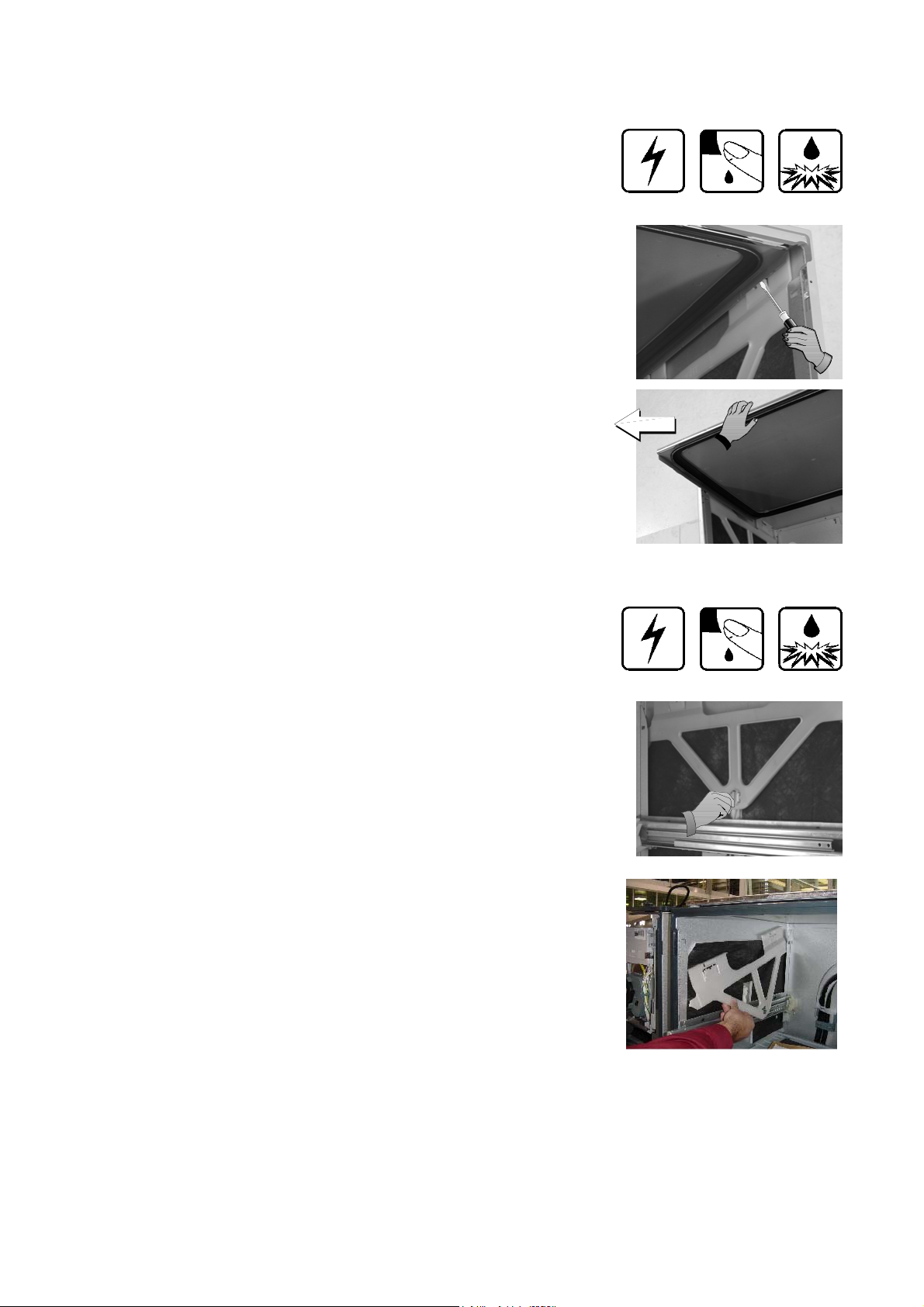
March 2004 Manual 599082
9.13 Lid Removal
9.13.1 Remove tub assembly as per instructions in 9.2.
9.13.2 On the right-hand side of the lid release the two tabs that clip the lid
to the yoke. Repeat for the left-hand side.
9.13.3 The lid is now free to slide out of the chassis.
9.13.4 Refit in the reverse manner taking care that the lid is fitted the
correct way around. The front is indicated on the top of the lid.
9.14 Yoke Removal
9.14.1 Remove the lid as per instructions in 9.13.
9.14.2 Release the lid actuator connecting arm from the bottom of the yoke
by squeezing the two tabs towards each other.
9.14.3 Slide the front of the yoke downwards at an angle until it moves out
of the track in the rear of the trim, and is clear of the chassis flange.
9.14.4 Refit in the reverse manner taking care that the yoke is the correct
way around.
- 42 -
Page 43

March 2004 Manual 599082
9.15 Lid Actuator Removal
9.15.1 Remove the tub as per instructions in 9.2. For top tub lid
actuators the bottom tub must also be removed to gain access
to the lid actuator wiring harness.
9.15.2 Release the lid actuator connecting arm from the bottom of the
yoke by squeezing the two tabs towards each other.
9.15.3 Remove the cover from the chassis module as explained in
9.17. Disconnect the appropriate lid actuator wiring harness
from the chassis circuit board and unclip the wiring harness
back to the lid actuator.
9.15.4 For a right-hand lid actuator carefully release the clip at the
back of the lid actuator and slide the lid actuator towards the
rear of the chassis to release it from the slide rail.
9.15.5 For a left-hand lid actuator the clip is at the front
of the lid actuator and once released the lid actuator will slide
towards the front of the chassis to release it from the slide rail.
9.15.6 The lid actuator can now be removed.
9.15.7 When reconnecting a lid actuator to a yoke it is recommended to have the lid and yoke assembly pushed
hard up against the upper stops. To line up correctly, the lid actuator connecting arm screw may need to be
wound up or down manually prior to clipping to the yoke. Care needs to be taken when working on a lower
tub that the lid and yoke assembly don’t accidentally get fitted above the upper stops.
Note; it is important that all the clips on the lid actuator case are done up and that none are broken.
- 43 -
Page 44

March 2004 Manual 599082
9.16 Slide Rail Replacement
9.16.1 Remove the Tub as per instructions in 9.2.
9.16.2 Remove the lid actuator from the slide rail as per instructions in
9.15.
9.16.3 Bottom slide rails only. The lower plastic chassis trim must be
removed as per instructions in 9.22 to gain access to the screws
securing the front of the slide rail. Remove the two hex drive screws
securing the slide runner at the front.
9.16.4 Tap the slide rails from underneath at the front.
This will knock the slide rail up and free from its location in the
chassis.
9.16.5 The slide runner may now be pulled forward to release it from its
location in the rear of the chassis.
9.16.6 Refit in reverse manner.
9.17 Chassis Circuit Board / Flood Sensor Removal
9.17.1 Remove lower tub as per instructions in 9.2.
9.17.2 Release clip on chassis module cover and slide cover to the
right to remove.
9.17.3 Disconnect all wiring to the chassis circuit board taking care
not to damage the small lid actuator motor plugs.
9.17.4 Remove centre earth screw from chassis circuit board.
9.17.5 Release the clip holding the left-hand end of the circuit board
down.
9.17.6 Carefully lift the left-hand end of the circuit board up and then
to the left taking care not to damage the flood sensor.
9.17.7 Refit in reverse manner
- 44 -
Page 45

March 2004 Manual 599082
9.18 Water Valve Removal
9.18.1 Remove the lower tub as per instructions in 9.2.
9.18.2 Remove the chassis module cover as per instructions in 9.17.
9.18.3 Disconnect the wiring connections to both solenoid coils. Release
the locking tabs for the connectors with a blade screwdriver while
doing this.
9.18.4 Disconnect the inlet hose connection.
9.18.5 You can now slide the water valve up out of its mounting bracket.
9.18.6 Disconnect the two fill hoses off the valve noting which hose goes to
the top and tub and which goes to the bottom tub.
9.18.7 Refit in reverse manner.
9.19 Fill Hose, Drain Hose, Wiring Harness Replacement
9.19.1 Remove wiring cover as per instructions in 9.9.
9.19.2 Remove tub as per instructions in 9.2.
9.19.3 From the tub end disconnect the component you need to replace
(fill hose, drain hose, wiring harness).
9.19.4 Remove the relevant component from each of the three link clips
and the chassis clips holding it.
Do this one at a time marking its position at each clip in the link
and closing each clip after the component is removed to keep
the other two components clipped in the correct position.
9.19.5 The component can now be disconnected from the chassis end
and removed.
9.19.6 Refit in the reverse manner ensuring the link clips are clamping
the components in their correct location.
- 45 -
Page 46

March 2004 Manual 599082
9.20 Link Support Replacement
9.20.1 Mark the position of the link support clips on the fill hose, drain
hose and harness.
9.20.2 Undo the clips and remove the link support.
9.20.3 fit the new link support.
9.20.4 Check the clips are in the same position as the original. The wire
ties on the wiring harness need to be located inside the clips
9.20.5 If they are not, it could prevent the tub from closing fully, which
may cause the product to “Pause” part way through the cycle, or
9.20.6 The link support may interfere with and reset the latch while the
Drawer is closing.
9.21 Toe Kick Removal
9.21.1 Partly open bottom drawer.
9.21.2 Loosen the right and left hand toe kick screws.
9.21.3 Slide the toe kick towards the front of the tub until it comes of the
mounting rails.
9.21.4 Refit in reverse manner.
9.22 Lower Tub Cowling
9.22.1 Remove the lower drawer front as per instructions in 9.2.
9.22.2 Remove the toe kick as per instructions in 9.20.
9.22.3 Release the centre clip as shown and slide the cowling forward.
9.22.4 Refit in the reverse manner
- 46 -
Page 47

March 2004 Manual 599082
9.23 Front Trim Replacement
9.23.1 First remove both the left and right hand yokes as per instructions in
9.14. This is to prevent damaging the locating tab at the front of
each yoke which fits into the trim.
9.23.2 The trim has to be removed by breaking the retaining clips.
9.23.3 This can be done by slipping a blade screwdriver between the trim
and the chassis and twisting the blade to snap the clips. Protect the
cabinet from chipping and remove the broken clips so they don’t fall
in to the tub and damage the rotor.
9.23.4 Check that a light prism is fitted in to the trim.
9.23.5 Remove the drawer front and handle as per instructions in 9.1 and
9.3 so the replacement trim can be fitted over the tub.
9.23.6 Line up the clips on the replacement trim with
the holes in the chassis and push home.
9.24 Water Softener
9.24.1 Remove the Drawer Front as per instruction 9.1
9.24.2 Disconnect the Wiring Loom connections to the Water Softener Diverter valve, Brine pump and Salt Level
Detector and remove the Dispenser Wiring Loom connection to the Electronic Controller.
9.24.3 Use a flat bedded screwdriver to open the Salt Level Indicator LED cover and remove the LED from the
Water Softener.
9.24.4 Unclip the Fill Hose and the Dispenser Hose form the Water Softener.
9.24.5 Remove the 4 T10 torx drive screws securing the Water Softener to the Tub
9.24.6 The Water Softener can now be removed from the Product
9.24.7 To refit, place the Overflow O’ring on the Water Softener and lubricate the Tub overflow with a water soluble
lubricant e.g Glycerol or similar.
9.24.8 Place the Salt Tank O’ring in the tub. Lubricate the Salt Tank flange on the Water Softener.
9.24.9 Pass the Dispenser Wiring Loom through the Water Softener and plug it into the Electronic Controller.
9.24.10 Place the Water Softener in the Tub and apply enough pressure to seat the O’rings.
The Overflow should sit almost flush with the inside of the Tub.
The Salt Tank should be recessed by approx. 1mm from the inside of the Tub.
9.24.11 Refit in the reverse manner.
- 47 -
 Loading...