

Page 1

SINGLE DISHDRAWER™ DISHWASHER
CONTEMPORARY
DD24SA9, DD24SDT9 & DD24STN9
PROFESSIONAL
DD24SVT9
INSTALLATION GUIDE
US CA
Page 2

Page 3
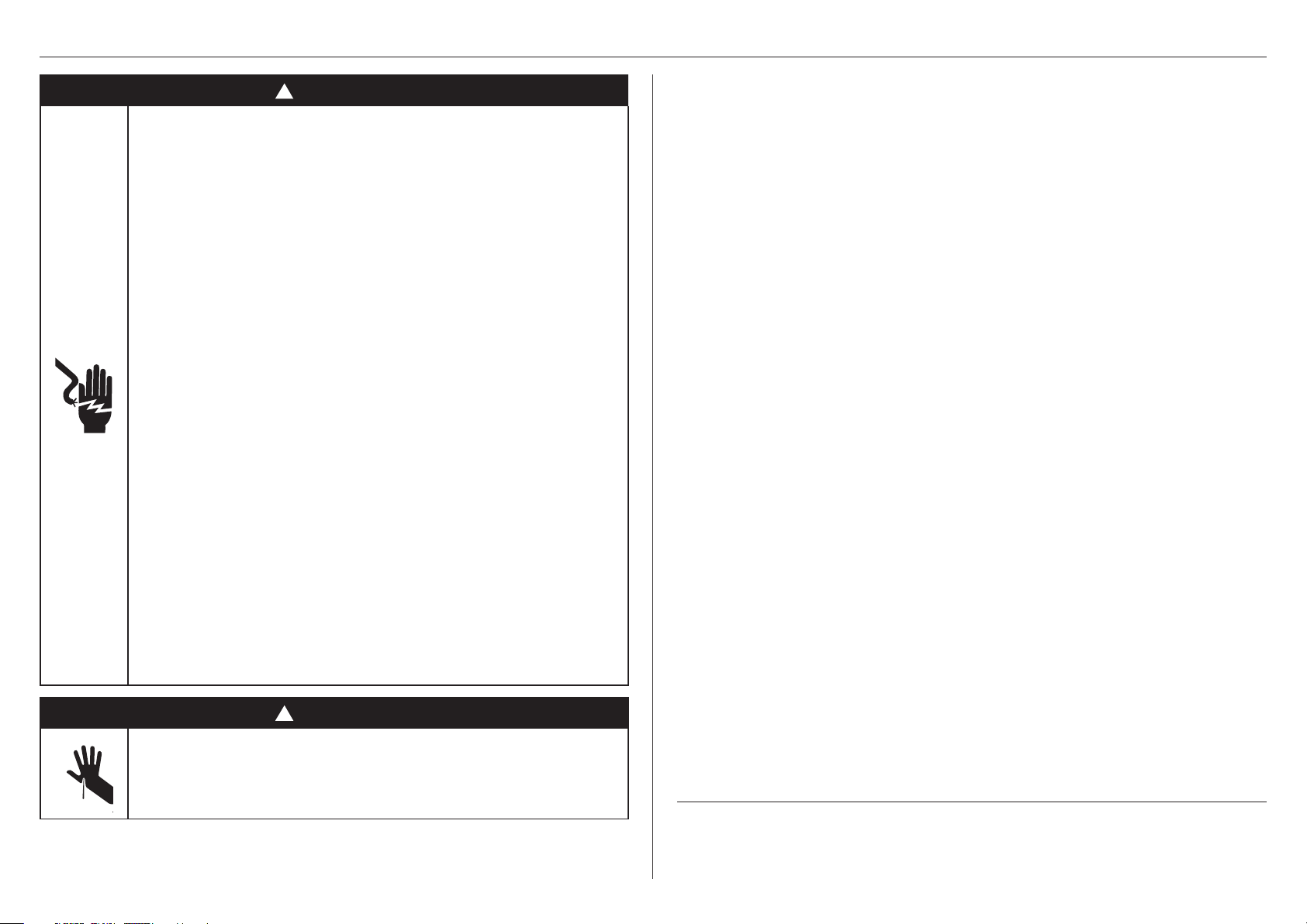
SAFETY AND WARNINGS
!
WARNING!
Electric Shock Hazard
Failure to follow this advice may result in
electrical shock or death.
• Before installing the DishDrawer, remove the
house fuse or open the circuit breaker.
• This appliance must be earthed. In the event of a
malfunction or breakdown, earthing will reduce
the risk of electric shock by providing a path of
least resistance for electric current. This appliance
is equipped with a cord having an equipmentearthing conductor and an earthing plug.
• The plug must be plugged into an appropriate
outlet that is installed and earthed in accordance
with all local codes and ordinances.
• WARNING - Improper connection of the
equipment-earthing conductor can result in a
risk of electric shock. Check with a qualified
electrician or service representative if you are in
doubt as to whether the appliance is properly
earthed.
• Do not modify the power supply plug provided
with the appliance - if it will not fit the outlet,
have a proper outlet installed by a qualified
electrician. Do not use an extension cord, adapter
plug or multiple outlet box.
WARNING!
To reduce the risk of fire, injury to persons or damage when using the appliance, follow the
important safety instructions listed below. Read all the guidance before using the appliance.
Servicing
z
Do not repair or replace any part of the appliance unless specifically recommended in
this guide. All other servicing should be undertaken be a Fisher & Paykel trained and
supported service technician or qualified person.
Installation
z
Installation of this DishDrawer requires basic mechanical and electrical skills.
z
Installation must comply with your local building and electricity regulations.
z
Remove all packaging materials supplied with the dishwasher.
z
Be sure to leave these Instructions with the Customer.
z
At the completion of the installation, the Installer must perform the Final Checklist.
z
This dishwasher is manufactured for indoor use only.
z
Ensure all water connections are turned OFF. It is the responsibility of the plumber and
electrician to ensure that each installation complies with all Codes and Regulations.
z
The DishDrawer MUST be installed to allow for future removal from the enclosure if
service is required.
z
The switched power outlet must be outside the dishwasher cavity, so that it is
accessible after installation.
z
Care should be taken when the appliance is installed or removed to reduce the
likelihood of damage to the power supply cord and hoses.
z
If the DishDrawer is relocated from one installation site to another it must be kept
upright to avoid damage from water spillage.
z
Ensure only supplied hoses are used for connection. Old hoses should not be reused.
z
Failure to install correctly could invalidate any warranty or liability claims.
z
If the product is installed in a motor vehicle, boat or similar mobile facility, you must
bring the vehicle, boat or mobile facility containing the product to the service shop at
your expense or pay the service technician’s travel to the location of the product.
z
This appliance is fitted with a water heating feature and intended for connection to a
hot water supply.
!
WARNING!
Cut Hazard
Failure to use caution could result in injury.
• Take care - panel edges are sharp.
SAVE THESE INSTRUCTIONS
The models shown in this installation guide may not be available in all markets and are subject to
change at any time. For current details about model and specification availability in your country,
please go to our website www.fisherpaykel.com or contact your local Fisher&Paykel dealer.
3
Page 4
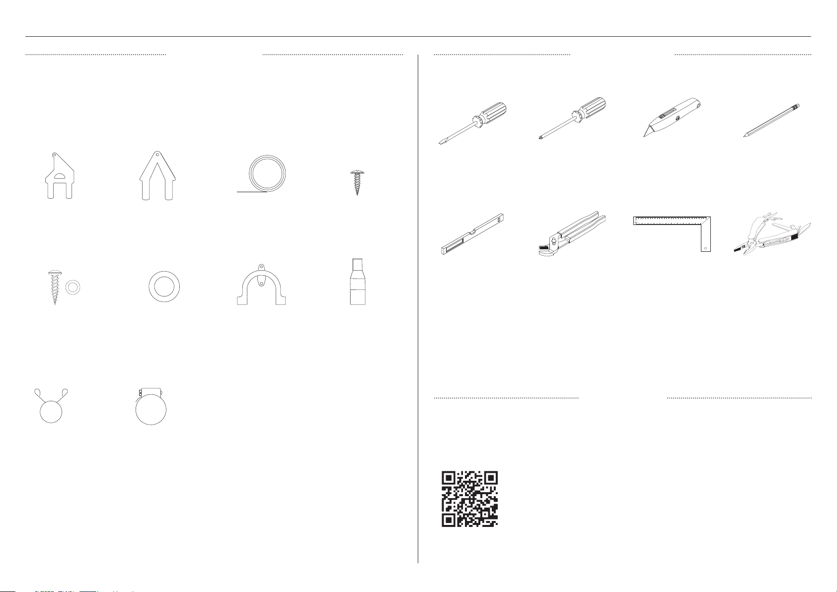
TOOLS AND COMPONENTS
PARTS SUPPLIED TOOLS REQUIRED
z
Keep all packing materials until the unit has been inspected.
z
Inspect the product to ensure there is no shipping damage. If any damage is detected
contact the dealer or retailer you bought the product from to report the damage.
z
Fisher & Paykel is not responsible for shipping damage.
Supplied
Not supplied
Side mounting bracket
kits (2)*
38mm bottom fixing
screws and washers (2)
Wire clip (1)
Top mounting bracket
kit (1)*
Rubber washer (1)** Drain hose support (1)
Clamp (1)
Moisture protection
tape (1)
16mm Phillips screws (7)
Drain hose joiner (1)
Flat-blade screwdriver
Level
Powered driver
Pliers
Box cutter
Router
Pencil
Multi-tool
INSTALL VIDEO
This video provides an overview of what is needed to install a DishDrawer™ Dishwasher. It is
intended as an overview only of the installation process and is not intended to be used as a
standalone guide on how to install a DishDrawer™ Dishwasher yourself. Installation should be
undertaken by a Fisher & Paykel trained and supported service technician or qualified person.
*optional | **comes fitted to the product | ***DD24DA models only | ****DD24DC & DD24DD models only
4
To access installation videos
Scan the QR code with your smartphone or watch online at:
fisherpaykel.com/dishdrawer-install
Page 5
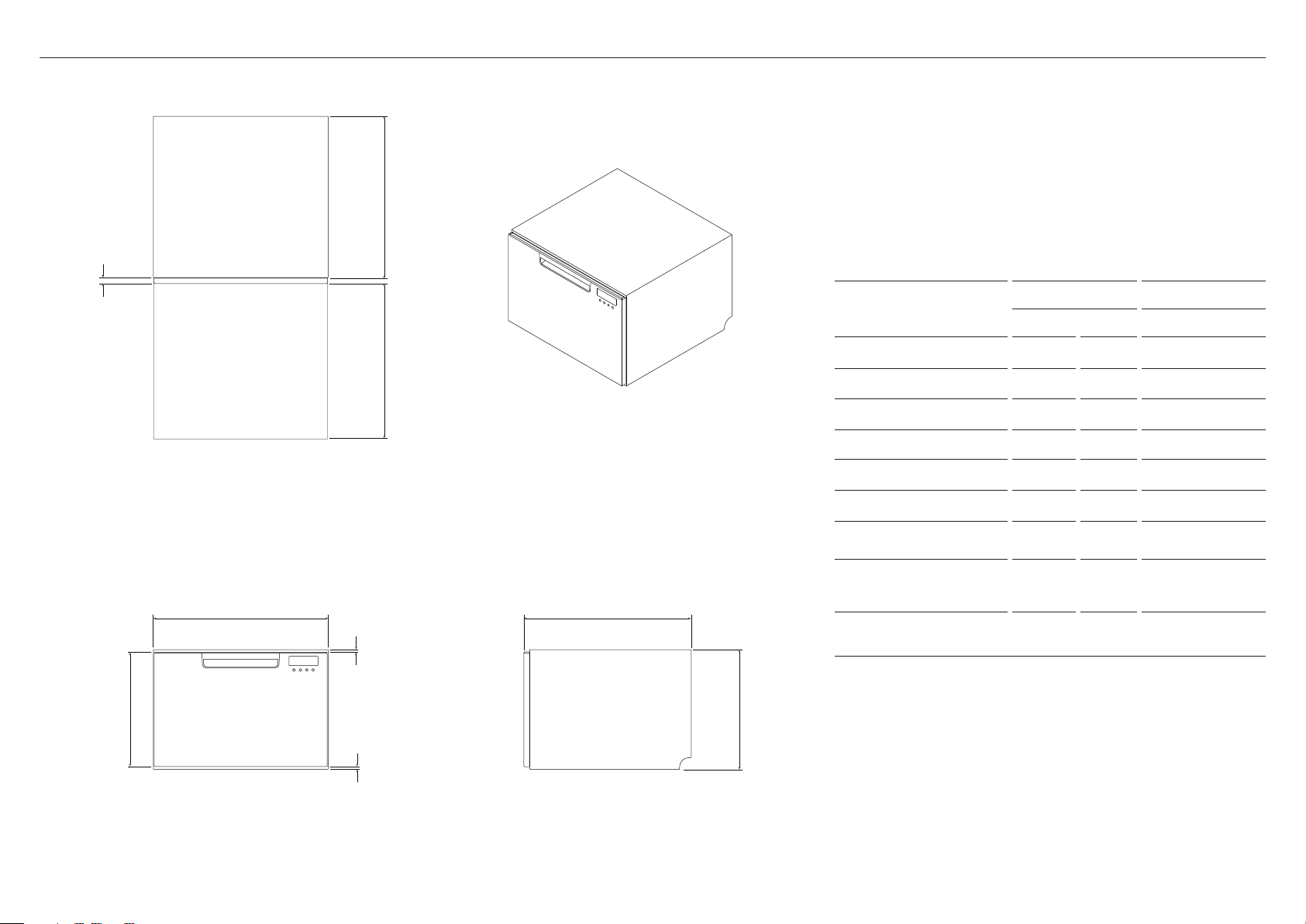
PRODUCT DIMENSIONS — DD24SC MODELS
D
f
DD24SC/SA DD24SCT
PRODUCT DIMENSIONS
INCHES MM INCHES MM
I
PLAN ISOMETRIC
Cb
h
E
A
A Overall height 16 1/8 410 17 7/8 454
B Overall width 23 9/16 599 23 9/16 599
C Overall depth 22 9/16 573 22 9/16 573
D Depth of chassis 21 3/4 553 21 3/4 553
E Height of door panel 15 1/2 394 17 1/4 438
F Depth of door panel 13/16 20 13/16 20
G Ventilation gap below
door panel
H Height from top of
drawer panel to top
5/16 8 5/16 8
5/16 8 5/16 8
of chassis
I Max. drawer extension
from front of chassis
21 9/16 547 21 9/16 547
g
PROFILEFRONT
Actual product dimensions may vary by ± 1/16” (2 mm)
5
Page 6
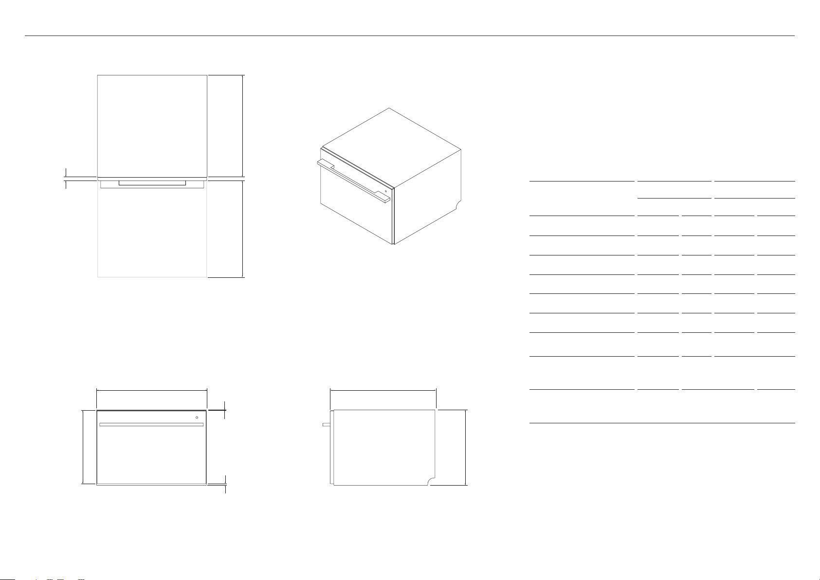
PRODUCT DIMENSIONS — DD24SD MODELS
D
f
PRODUCT
DIMENSIONS
INCHES MM INCHES MM
DD24SD DD24SDT
I
PLAN ISOMETRIC
Cb
h
E
g
A
A Overall height 16 1/8 410 18 13/16 478
B Overall width 23 9/16 599 23 9/16 599
C Overall depth* 22 9/16 573 22 9/16 573
D Depth of chassis 21 3/4 553 21 3/4 553
E Height of door panel 15 11/16 398 18 1/2 470
F Depth of door panel 13/16 20 13/16 20
G Ventilation gap
below door panel
H Height from top of
drawer panel to top
8 5/16 8 5/16 8
1/16 2 1 26
of chassis
I Max. drawer
extension from front
21 9/16 547 21 9/16 547
of chassis
*excluding handle
PROFILEFRONT
6
Actual product dimensions may vary by ± 1/16" (2 mm)
Page 7
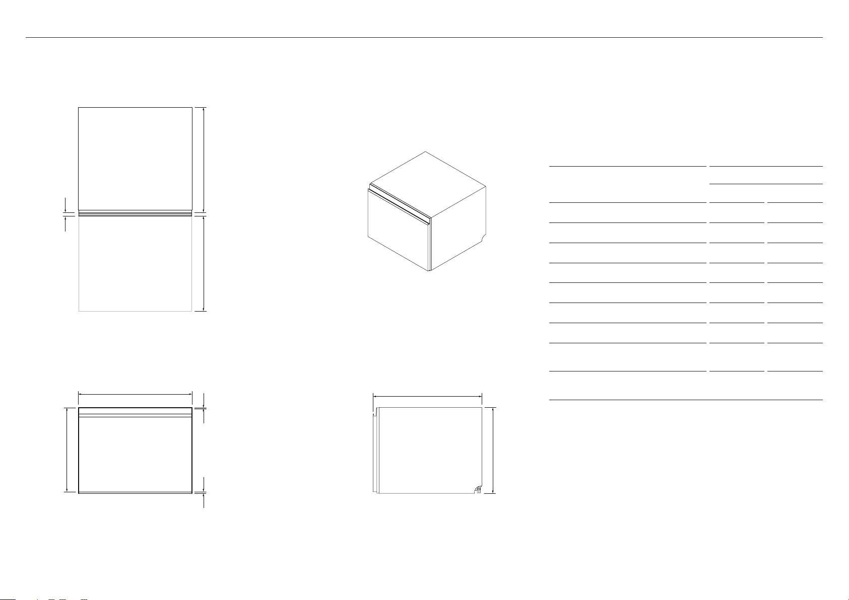
PRODUCT DIMENSIONS — DD24STN MODELS
d
PRODUCT DIMENSIONS
DD24STN
INCHES MM
f
i
PLAN ISOMETRIC
b
h
c
aE
A Overall height 17 13/16 454
B Overall width 23 9/16 599
C Overall depth 22 9/16 573
D Depth of chassis 21 3/4 553
E Height of door panel 17 3/8 442
F Depth of door panel 13/16 20
G Ventilation gap below door panel 5/16 8
H Height from top of drawer panel
to top of chassis
I Max. drawer extension from front
of chassis
1/16 2
21 9/16 547
g
PROFILEFRONT
Actual product dimensions may vary by ± 1/16" (2 mm)
7
Page 8
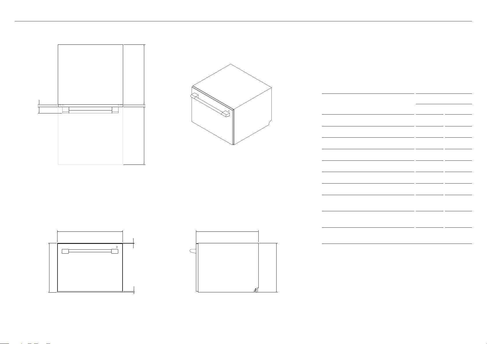
PRODUCT DIMENSIONS — DD24SV2T9 MODELS
D
f
DD24SV2T9
PRODUCT DIMENSIONS
i
A Overall height 17 7/8 454
j
PLAN ISOMETRIC
B Overall width 23 9/16 599
C Overall depth* 22 9/16 573
D Depth of chassis 21 3/4 553
E Height of door panel 17 3/8 442
F Depth of door panel 13/16 20
G Ventilation gap below door panel 5/16 8
H Height from top of drawer panel
to top of chassis
I Depth of handle 2 1/4 58
Cb
J Max. drawer extension from front
of chassis
h
*excluding handle
INCHES MM
1/16 2
21 9/16 547
E
g
A
PROFILEFRONT
8
Actual product dimensions may vary by ± 1/16" (2 mm)
Page 9
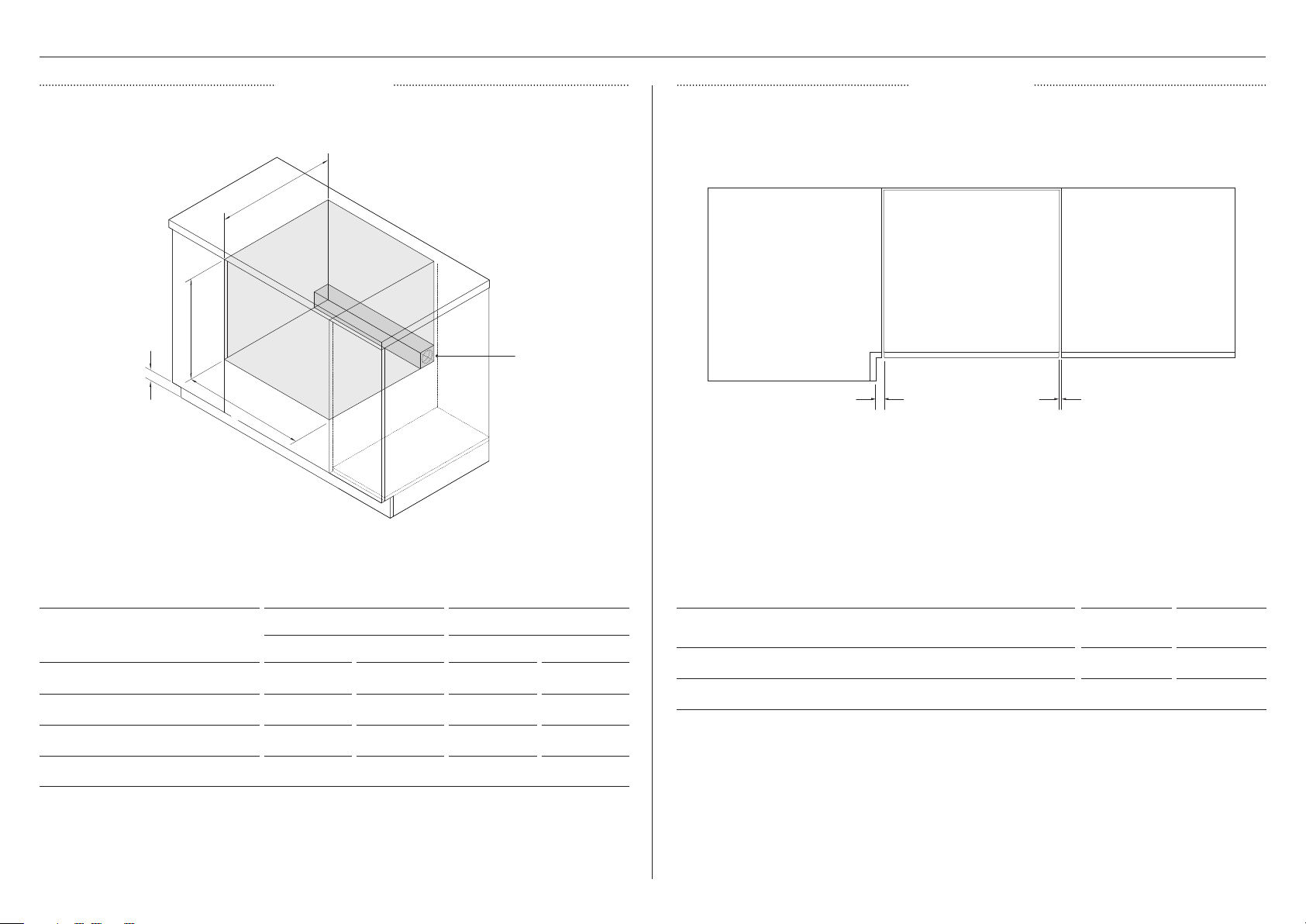
DIMENSIONS CLEARANCES
Ensure the relationship between benchtop overhang and the recessed handle has been
considered.
C
CABINETRY
A
D
Connections can
be located in an
adjacent cabinet
on either side of
the DishDrawer™
Dishwasher***
B
ISOMETRIC
STD MODELS TALL MODELS
CABINETRY DIMENSIONS
INCHES MM INCHES MM
A Minimum inside height min. 16 1/4 min. 412 min. 17 15/16 min. 456
B Inside width 23 5/8 600 23 5/8 600
C Minimum overall depth* 22 13/16 579 22 13/16 579
D Minimum toe kick height** 3 15/16 100 3 15/16 100
*including 3/4" (19mm) door panels on adjacent cabinetry
**when venting through the same or adjacent cabinet
***for more information on service requirements, refer to 'Plumbing & electrical considerations' and 'Cabinetry preparation'
B A
PLAN
CABINETRY CLEARANCES INCHES MM
A Minimum clearance to adjacent cupboard door 1/16 2
B Minimum clearance to corner cupboard 1/2 13
9
Page 10
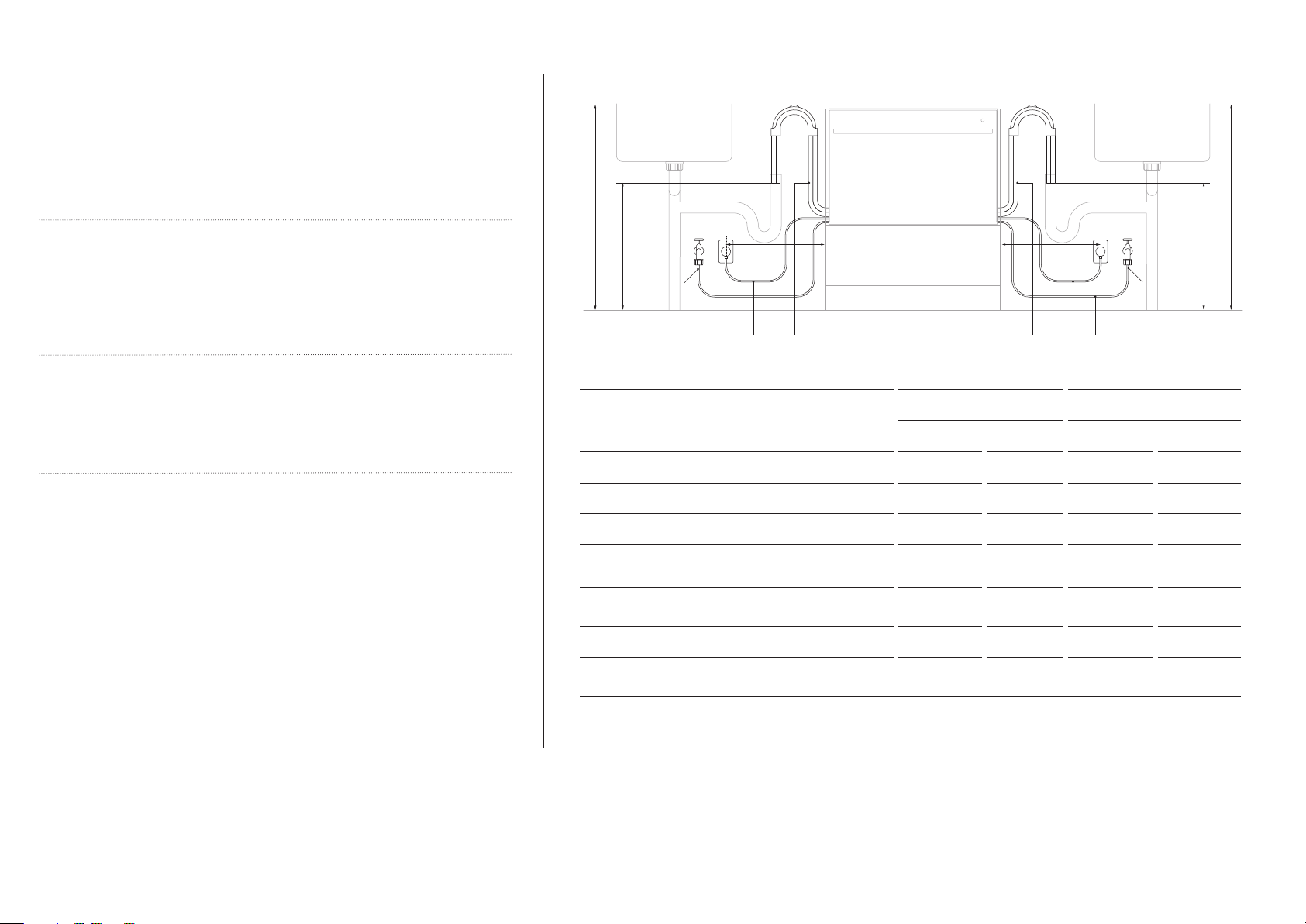
Hose and cord lengths
z
Your services can be installed to either the left-hand or right-hand side
of the product in an adjacent cabinet. Refer to ‘Cabinetry preparation’
for service access requirements.
z
If the drain hoses supplied are not long enough to reach your services,
you may purchase a Fisher & Paykel drain hose extension kit which will
extend the drain hoses by 3.6m (part number 525798).
Water connection
z
Recommended water temperature: Hot (maximum 140°F (60°C))
z
Supplied hose to suit 3/8" male compression fitting.
z
Ensure water connection complies with local plumbing regulations.
PLUMBING & ELECTRICAL CONSIDERATIONS
d d
e e
f f
a a b cbc
Water pressure
z
Water softener models: max. 1 MPa (145 psi), min. 0.1 MPa (14.5 psi)
z
Non-water softener models: max. 1 MPa (145 psi), min. 0.03 MPa (4.3 psi)
Electrical requirements
z
120V (60Hz) min 4.2A
SERVICE DIMENSION
LEFT SIDE* RIGHT SIDE*
INCHES MM INCHES MM
A Length of drain hoses 78 3/4 2000 7 0 7/ 8 1800
B Length of power cord** 64 15/16 1650 64 15/16 1650
C Length of inlet hose 64 15/16 1650 49 3/16 1250
D Distance from floor to top of hose support
E Minimum distance from floor to end of
drain hoses***
29 1/2 –
34 3/4
750 – 883
19 11/16 500 19 11/16 500
29 1/2 –
34 3/4
750 – 883
F Minimum inlet hose radius 7 7/ 8 200 7 7/ 8 200
G Maximum distance from cabinetry centre of
electrical outlet
*dimensions taken from the chassis edge where applicable
**excluding plug
***standpipe install illustrated. Distance is the same for all plumbing installs.
17 3/4 450 17 3/4 450
10
Page 11
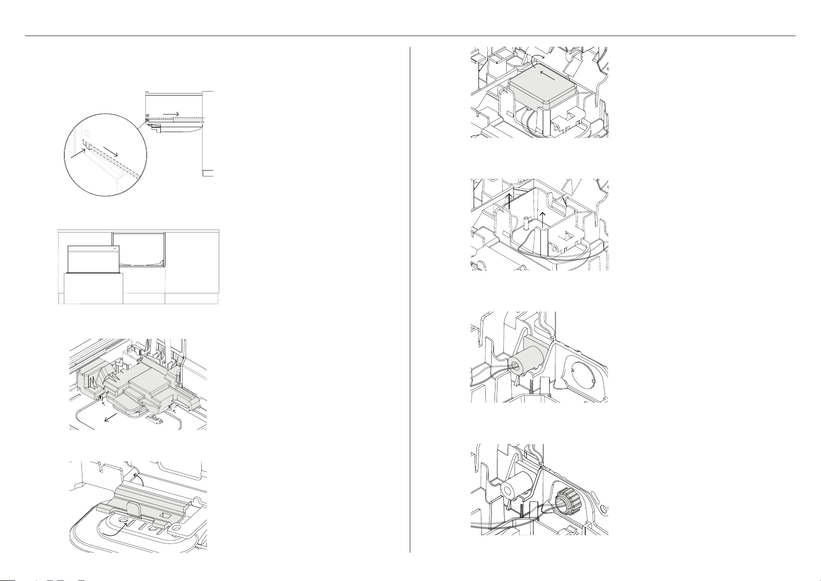
HARD-WIRING (OPTIONAL)
You have the option to hard-wire your DishDrawer™ Dishwasher. To do this, we recommend
to remove the supplied power cord and do the hardwiring installation as close to the cavity
as possible. Ensure only copper conductors are used.
5
Slide the terminal block cover sideways
to unlock and hinge open to access the
terminal block.
1
2
3
Open the drawer and press both
locking tabs back to release.
Lift the drawer off the runners and
carefully set aside on a protected
surface. Push runners back in.
Take care not to pull drawer out too
far to prevent any strain on the hoses.
Where possible, protect the base of the
tub to prevent damage.
With a flat-bladed screwdriver, push in
the clips and slide out the access cover.
6
7
Unscrew the Live, Neutral and Earth
wires as shown.
Safely cut the cord from the inside
and outside of the product to remove
the cord.
4
With a screwdriver, unclip the plastic
harness cover and hinge open.
8
Fit a suitable cable clamp for the
conduit through the metal knockout.
Ensure wiring is routed through or under
under housing ribs.
11
Page 12
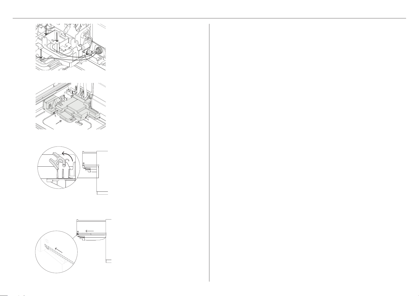
HARD WIRING (OPTIONAL)
9
!0
!1
Screw down the Live, Neutral and Earth
wires correctly.
Refit module cover before sliding the
access cover back into place, ensuring
the 2 clips shown are fully locked.
Before refitting the drawer, ensure the
hoses are not twisted.
Refit the drawer to the runners and
clip into place via both locking tabs.
!2
12
Refit the drawer back onto the
runners, ensure both runners are
entended halfway before lowering
the tub. Slide the runners forward
to engage.
Page 13
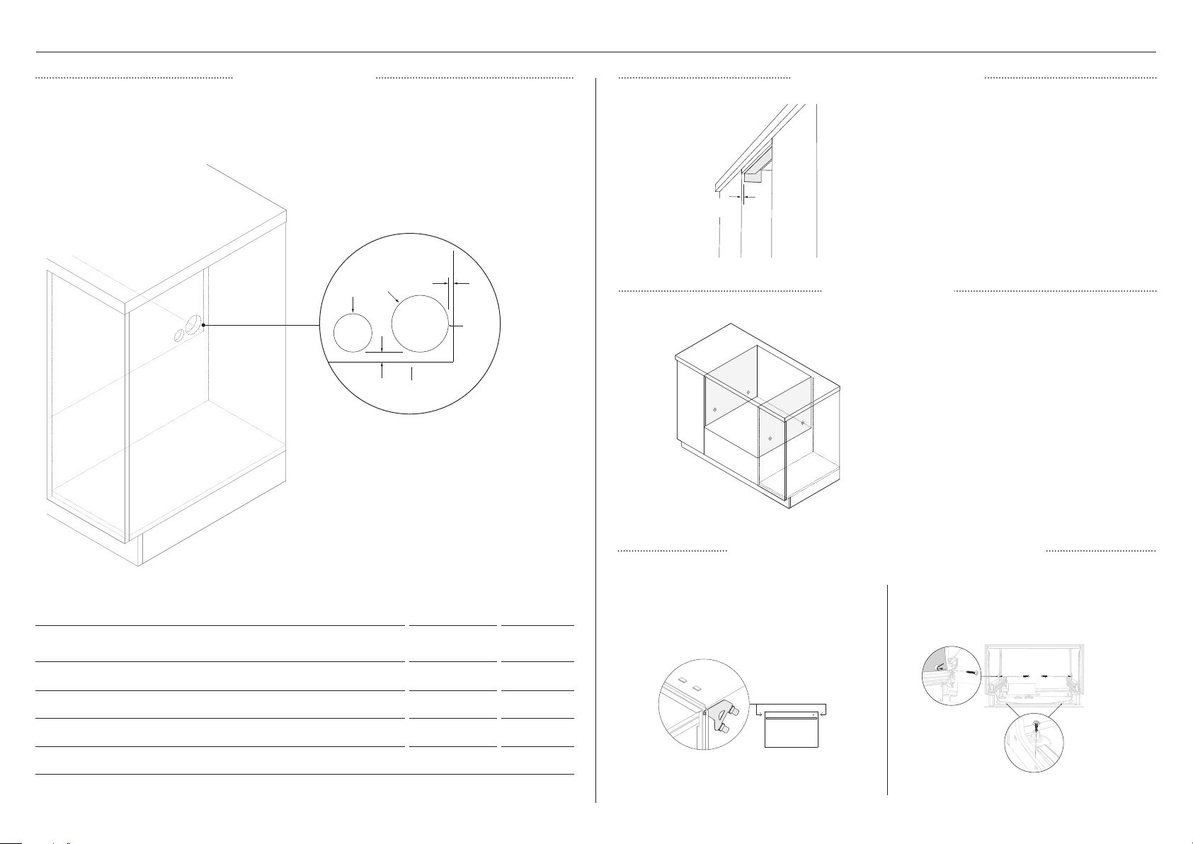
CABINETRY PREPARATION
SERVICE ACCESS
z
Service holes can be created on either side of the DishDrawer™ Dishwasher cavity as
shown below.
z
If the hole is created through wood, ensure the edges are smooth and rounded.
z
If the hole is created through metal, ensure the edge protector is fitted.
SHELF*
A
REAR
WALL
C
D
B
PROFILE
1
1
3/8"
(10mm)
MOISTURE PROTECTION
Align the supplied moisture protection
tape to the cabinetry as illustrated
Ensure this area is free of debris
before carefully applying the tape to
the surface.
SIDE PARTITION
If securing via the drawer removal method,
ensure the marked locations provide
adequate support.
If there are no side partitions, construct timber
bracing to secure the fixings to.
SERVICE HOLE DIMENSIONS INCHES MM
A Maximum distance between rear of cavity and service hole 1/4 5
B Maximum distance between shelf and service hole 1/2 10
C Minimum diameter of hose service hole 2 1/4 57
D Maximum diameter of power cord service hole 1 1/2 38
*for assisted opening installations, maximum distance should be referenced from the top of the spacer blocks
SELECT CABINETRY SECURING METHOD
METHOD A
Secure to cabinetry via brackets
Recommended method*
*frameless cabinetry only
METHOD B
Secure via drawer removal
13
Page 14
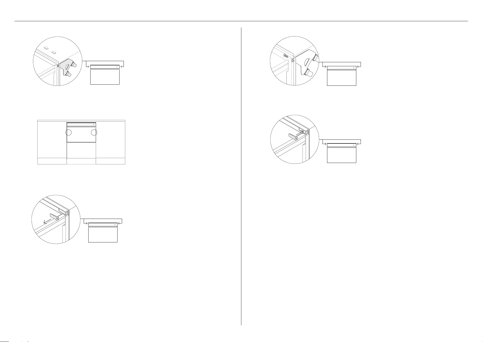
1
2
SECURE TO CABINETRY VIA BRACKETS (METHOD A)
Secure all four side brackets to the
DishDrawer™ Dishwasher, aligning
bracket A with slot A and bracket B
B
A
A
with slot B.
Ensure the ends of the brackets are not
B
pushed into the chassis.
Push the product into the cavity, pulling
the hoses through as you push to avoid
crushing or twisting them.
Push the product in the positions
illustrated to avoid denting the door.
4
5
Secure to cabinetry via the brackets.
Pre-drilling a pilot hole may be required
depending on the cabinetry material.
Replace the trim cover and repeat for
the remaining brackets.
3
14
Partially open the drawer and
remove the first screw cover from
the trim moulding.
Page 15
1
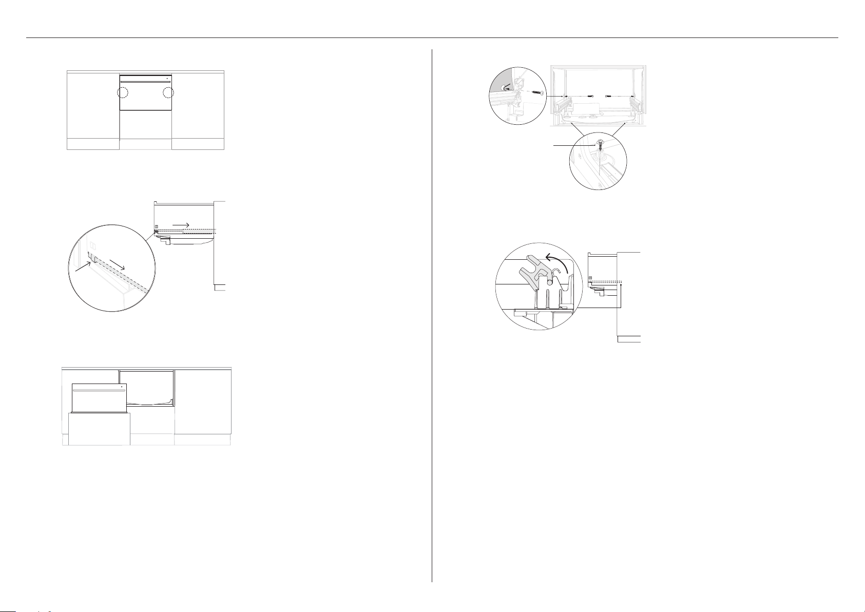
SECURE TO CABINETRY VIA DRAWER REMOVAL (METHOD B)
Push the product into the cavity, pulling
the hoses through as you push to avoid
crushing or twisting them.
Push the product in the positions
illustrated to avoid denting the door.
4
38mm screw
and large washer
Secure to cabinetry via all three fixing
locations in the chassis.
Ensure sound insulation is
replaced correctly.
2
3
Open the drawer and press both
locking tabs back to release.
Lift the drawer off the runners and
carefully set aside on a protected
surface. Push runners back in.
Take care not to pull drawer out
too far to prevent any strain on the
hoses. Where possible, protect the
base of the tub to prevent damage.
5
Before refitting the drawer, ensure the
hoses are not twisted.
Refit the drawer to the runners and clip
into place via both locking tabs.
15
Page 16
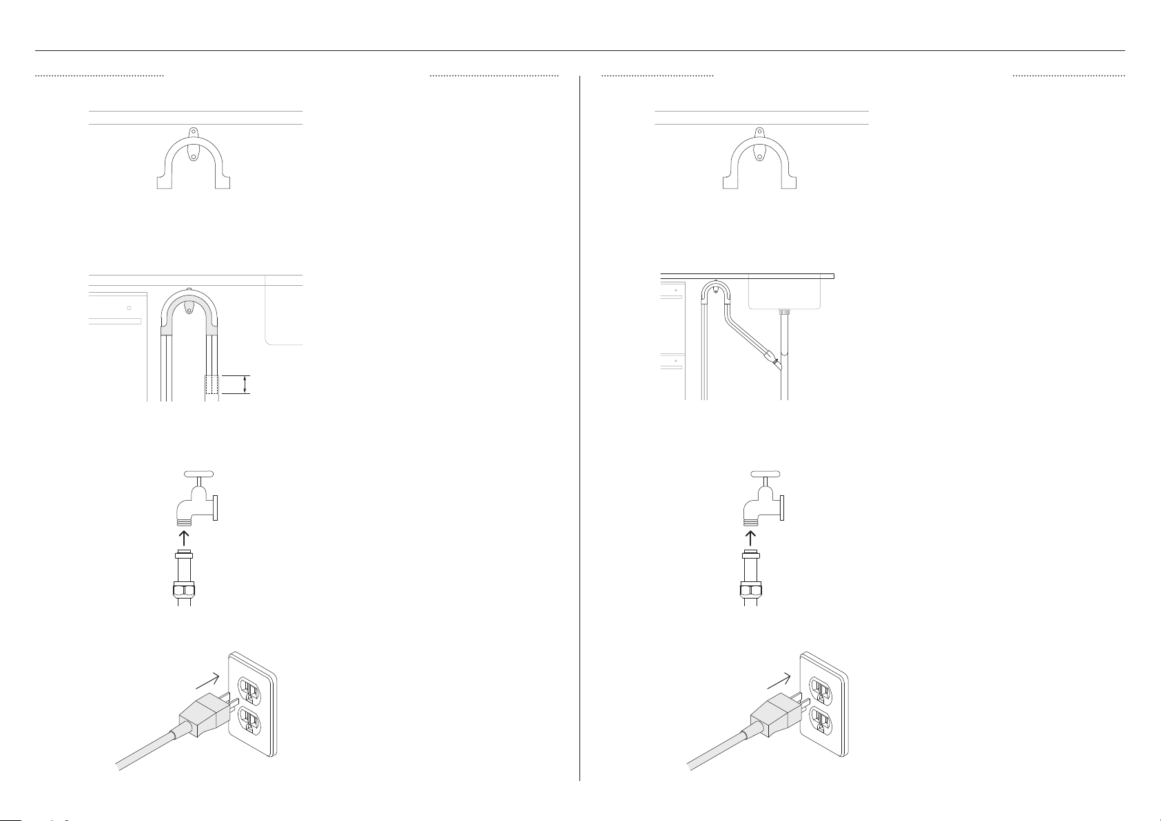
PLUMBING & ELECTRICAL CONNECTION
Ø38MM STANDPIPE INSTALLATION SINK TRAP/WASTE TEE INSTALLATION
Install the drain hose support to the
back wall, as close to the underside of
1 1
2 2
min.
4 3/4"
(120mm)
3 3
the countertop as possible. Refer to
‘Plumbing & electrical considerations’ for
minimum install heights.
Pull both hoses through the support
guide and rest in standpipe.
Ensure the drain hose does not extend
into water retained in the trap; an air
gap is required to prevent waste water
from siphoning back into the tub.
Connect the inlet hose to tap and handtighten into place.
Using a spanner or pliers, turn a further
180° to secure. Avoiding over-tightening.
Do not turn water supply on. The
DishDrawer™ Dishwasher must be
powered on for the flood protection
feature to be enabled.
Install the drain hose support to the
back wall, as close to the underside of
the countertop as possible. Refer to
‘Plumbing & electrical considerations’ for
minimum install heights.
Pull both hoses through the drain hose
support before threading the wire
clips on to the hoses and fitting to the
supplied hose joiner. Secure using the
wire clips.
Ensure hose is routed straight to the
joiner, removing excess drain hose if
necessary. Do not shorten the inlet hose.
Unplug or drill out the waste tee before
securing joiner to sink trap or waste tee.
Connect the inlet hose to tap and handtighten into place.
Using a spanner or pliers, turn a further
180° to secure. Avoiding over-tightening.
Do not turn water supply on. The
DishDrawer™ Dishwasher must be
powered on for the flood protection
feature to be enabled.
4 4
16
Plug product in.Plug product in.
Page 17
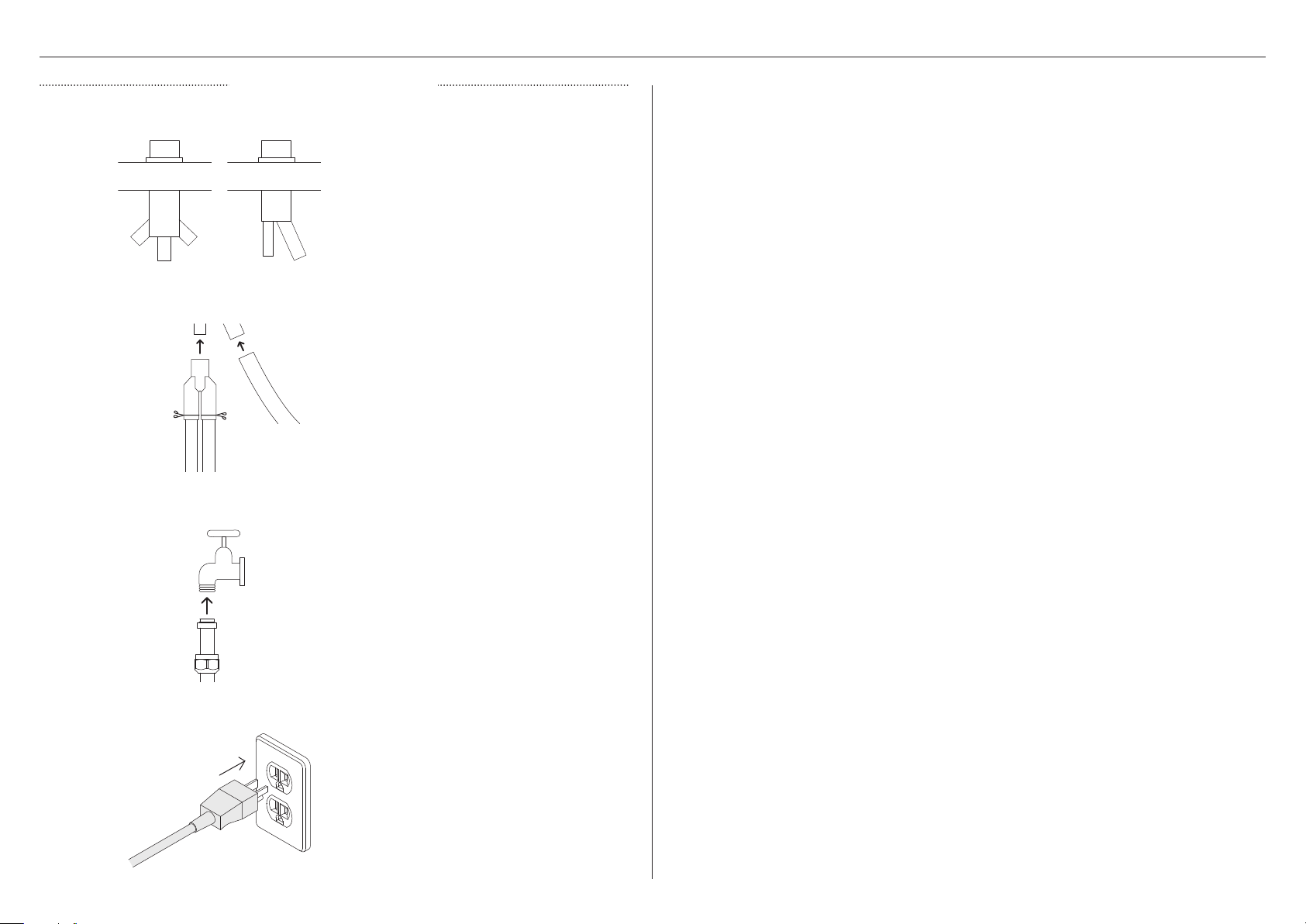
1
2
PLUMBING & ELECTRICAL CONNECTION
AIR GAP INSTALLATION
Install your Air Gap Kit to the benchtop.
We recommend using a Dual Air Gap Kit.
Refer to ‘Plumbing & electrical
connection’ for minimum install heights.
Dual Air Gap Single Air Gap
Thread wire clips onto the hoses before
fitting them to the hose joiner. Secure
using the wire clips. Fit the joiner to the
Air Gap Kit and secure using the hose
clamp. Ensure hoses are routed straight
to the joiner, removing excess drain hose
if necessary.
Unplug or drill out the waste tee before
securing to sink trap or waste tee.
3
4
Connect the inlet hose to tap and handtighten into place.
Using a spanner or pliers, turn a further
180° to secure. Avoiding over-tightening.
Do not turn water supply on. The
DishDrawer™ Dishwasher must be
powered on for the flood protection
feature to be enabled.
Plug product in.
17
Page 18

TO BE COMPLETED BY THE INSTALLER
INSTALLER CHECKLIST
Installation
Check all parts are installed correctly and are secure.
Ensure DishDrawer™ Dishwasher is securely fastened to the cabinetry and drawer opens
and closes freely with no resistance.
Ensure panel is fitted correctly to the DishDrawer™ Dishwasher
Ensure any packaging or tape securing the racks and spray arm is removed.
Check the spray arm is in place, mounted correctly and rotates freely.
Ensure knock-to-pause module is fitted securely and operating correctly.
Plumbing
Ensure any knock-outs or plugs in drain connection have been drilled out and drain
connection has been made.
The drain hose joiner must not support the weight of excess hose material. Keepdrain
hose as fully extended as possible to prevent sagging. Any excess length of drain hose
should be kept on the dishwasher side of the highloop.
Ensure inlet hose has supplied rubber washer fitted, and that it’s tightened.
Electrical
Ensure all electrical tests have been conducted in accordance with local regulations.
Test operation
Turn on the power and water supplies, then open the drawer. You should hear a beep
and see a program indicator light up on the control panel.
Add three cups of water into the drawer.
Navigate to RINSE and start the program.
Repeat for the other drawer.
After the Rinse cycle has finished, ensure the dishwasher has run and drainedcorrectly.
Check the water supply has been shut off correctly.
Check drainage connections for leaks.
If site is left without power after installation is complete, ensure water supply is
turned off to prevent flooding.
If connecting the drain hose to the sink trap, ensure the highloop is a minimum 150mm
higher than the drain hose joiner.
Water softener models: adjust the water softener setting from the default setting to suit
the water hardness of the area. Refer to your user guide.
Ensure water supply is turned off until power is connected and turned on. The
DishDrawer™ Dishwasher must be powered on for the flood protection feature to
be enabled.
18
Page 19
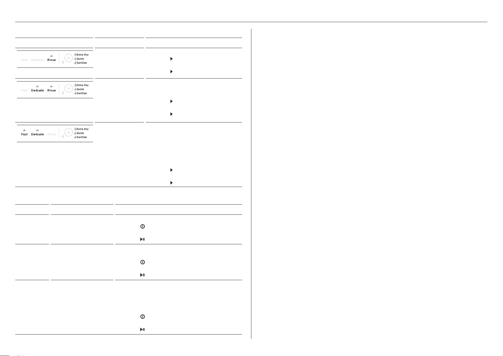
TROUBLESHOOTING
DD24SD, DD24SP, DD24ST4N and DD24ST4Z models
DISPLAY POSSIBLE CAUSE WHAT TO DO
A1: Water
Supply fault.
1 Ensure the water supply is turned on.
2 Press
then again to clear the fault.
RINSE + all modifiers
DELICATE, RINSE + all modifiers
FAST, DELICATE + all modifiers
A3: Drawer cannot
drain. The drainage
hose may be
blocked or kinked,
or the connection
to drainage pipe
may be blocked.
A6: The spray
arm has loosened
or come off its
mounting, or
water pressure
is too low, or a
combination of low
water pressure and
excessive foaming.
3 Press
1 Check the drainage hose and
connection for any blockages.
Ensure the spigot is drilled out.
2 Press
then again to clear the fault.
3 Press
1 Open the drawer and check the
spray arm.
2 If the spray arm has loosened or
come off its mounting, re-fit it.
Check that it is firmly seated and
turns freely. Refer to ‘Maintenance’
in your user guide.
3 Press
then again to clear the fault.
4 Press
DD24SA, DD24SC and DD24ST2N models
once to stop the beeping,
to resume the wash program.
once to stop the beeping,
to resume the wash program.
once to stop the beeping,
to resume the wash program.
The DishDrawer is beeping continuously
z
Refer to the ‘Fault codes’ section of your User guide
No program indicator lights up when the drawer is opened
z
Ensure power is connected and is switched on.
z
AUTO POWER-ON may need to be activated. Refer to your User guide for details.
Drawer doesn’t close properly
z
Ensure nothing is obstructing the drawer from closing such as hoses or drawer latches.
Water appears around water supply and drain connections
z
Check hoses, connections and existing plumbing for leaks.
z
Check rubber washer and hose clamp are correctly fitted.
Product is tipping
z
Ensure the product is secured to the cabinetry.
Front panels are misaligned to surrounding cabinetry
z
Check the cabinetry is square. Unscrew the product from the cabinetry. Re-secure to
the cabinetry.
If a problem occurs that is not listed, refer to your user guide for additional troubleshooting If
after checking these points, you still need assistance, please refer to the Service & Warranty
book for warranty details or contact us through our website fisherpaykel.com
DISPLAY POSSIBLE CAUSE WHAT TO DO
A1
Water supply fault. 1 Ensure the water supply is turned on.
2 Press
once to stop the beeping, then again
to clear the fault.
A3
A6
Drawer cannot drain. The
drainage hose may be
blocked or kinked, or the
connection to drainage
pipe may be blocked.
The spray arm has
loosened or come off
its mounting, or water
pressure is too low.
3 Press
1 Check the drainage hose and connection for any
blockages. Ensure the spigot is drilled out.
2 Press
to clear the fault.
3 Press
1 Open the drawer and check the spray arm.
2 If the spray arm has loosened or come off its
mounting, re-fit it. Check that it is firmly seated
and turns freely. Refer to ‘Maintenance’ in your
to resume the wash program.
once to stop the beeping, then again
to resume the wash program.
user guide.
3 Press
once to stop the beeping, then again
to clear the fault.
4 Press
to resume the wash program.
19
Page 20

FISHERPAYKEL.COM
© Fisher & Paykel Appliances 2023. All rights reserved.
The models shown in this guide may not be available in all markets
The product specifications in this guide apply to the specific products and
models described at the date of issue. Under our policy of continuous product
improvement, these specifications may change at any time.
For current details about model and specification availability in your country,
please go to our website or contact your local Fisher&Paykel dealer.
and are subject to change at any time.
4177A 04.2
 Loading...