

Fisher & Paykel DD24SA, DD24SCT Installation Instructions Manual

Single DishDrawerTM dishwasher
DD24SA & DD24SCT
models
US CA
INSTALLATION INSTRUCTIONS
591153A 07.16
www.fi sherpaykel.com
1
IMPORTANT!
SAVE THESE INSTRUCTIONS
The models shown in this installation guide may not be available in all markets and are subject to change at any time. For current details about model and specification availability in your country, please go to our
website www.fisherpaykel.com or contact your local Fisher & Paykel dealer.
IMPORTANT SAFETY INSTRUCTIONS
●
Installation of this dishwasher requires basic mechanical and electrical skills.
●
Be sure to leave these Instructions with the Customer.
●
Installation must comply with your local building, electricity, and plumbing regulations.
●
At the completion of the dishwasher installation, the Installer must perform the Final
Checklist.
●
Remove all packaging materials supplied with the dishwasher.
●
This dishwasher is manufactured for indoor use only.
●
Ensure all water connections are turned OFF. It is the responsibility of the plumber and
electrician to ensure that each installation complies with all Codes and Regulations.
●
The dishwasher MUST be installed to allow for future removal from the enclosure if
service is required.
●
The switched power outlet must be outside the dishwasher cavity, so that it is accessible
after installation.
●
Care should be taken when the appliance is installed or removed to reduce the likelihood
of damage to the power supply cord and hoses.
●
If the dishwasher is to be relocated from one installation to another it must be kept
upright to avoid damage from water spillage.
●
Make sure only new hoses are used for connection (supplied with the dishwasher). Old
hoses should not be reused.
●
Failure to install the dishwasher correctly could invalidate any warranty or liability claims.
●
If the product is installed in a motor vehicle, boat or similar mobile facility, you must
bring the vehicle, boat or mobile facility containing the product to the service shop at
your expense or pay the service technician’s travel to the location of the product.
●
This dishdrawer is intended for connection to the hot-water supply.
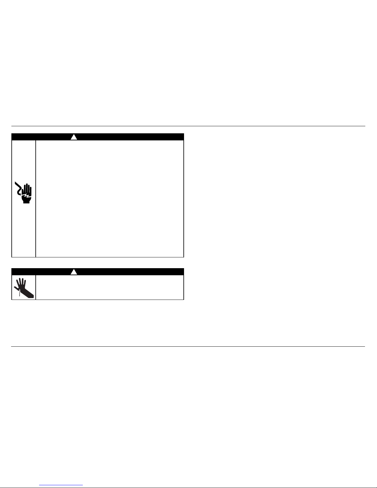
WARNING!
Electrical Shock Hazard
Before installing the dishwasher, remove the house fuse or open the circuit
breaker. If permanently connecting the dishwasher, be sure the power is
isolated and the dishwasher unplugged.
GROUNDING INSTRUCTIONS
This appliance must be grounded. In the event of a malfunction or breakdown,
grounding will reduce the risk of electric shock by providing a path of least
resistance for electric current. This appliance is equipped with a cord having
an equipment-grounding conductor and a grounding plug. The plug must be
plugged into an appropriate outlet that is installed and grounded in
accordance with all local codes and ordinances. WARNING - Improper
connection of the equipment-grounding conductor can result in a risk of
electric shock. Check with a qualified electrician or service representative if
you are in doubt as to whether the appliance is properly grounded.
If the dishwasher is installed as a permanently connected appliance:
GROUNDING INSTRUCTIONS - This appliance must be connected to a
grounded metal, permanent wiring system, or an equipment-grounding
conductor must be run with the circuit conductors and connected to the
equipment-grounding terminal or lead on the appliance.
Do not modify the power supply plug provided with the appliance - if it will
not fit the outlet, have a proper outlet installed by a qualified electrician. Do
not use an extension cord, adapter plug or multiple outlet box.
Failure to follow this advice may result in electrical shock or death.
WARNING!
Cut Hazard
Take care - panel edges are sharp.
Failure to use caution could result in injury or cuts.
!
!
1 SAFETY AND WARNINGS
2
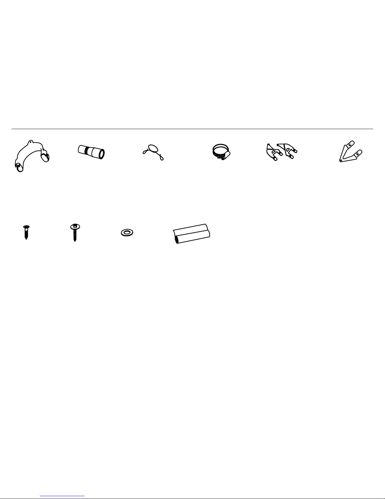
2 PARTS SUPPLIED
If the Drain hoses supplied are not long enough to reach your services, you must use a Drain Hose Extension Kit P/N 525798 which will extend the drain hoses by 3.6 m.
The kit is available from the nearest Fisher & Paykel Authorized Service Center or our local website listed at the end of this document.
Clamp (1)
(for securing
Drain hose joiner)
Wire clip (1)
(for securing
Drain hose joiner)
Phillips
5/8” (16mm)
screws (7)
1 1/2” (38mm)
bottom fixing
screws & metal
washers (2)
Drain hose
support (1)
Moisture protection
tape (1)
(to prevent moisture
damage to cabinetry)
Drain hose
joiner (1)
Top
mounting
brackets (2)
OPTIONAL
Rubber washer
for inlet hose (1)
(comes already
fitted)
Side mounting
bracket kit
(A and B) (2)
OPTIONAL
3
2
1
3
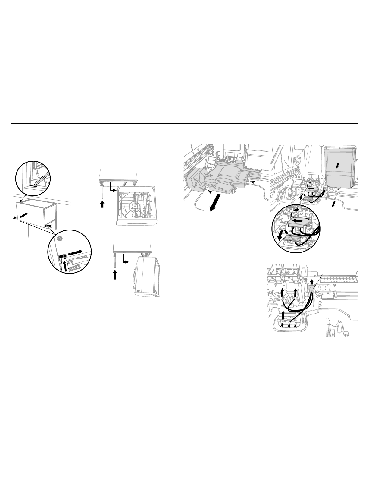
3 OPTIONALLY HARD WIRING PRIOR TO INSTALLATION
3-A REMOVE THE DRAWER 3-B REMOVE THE ACCESS COVER & REMOVE POWER
Access cover
Clip
Clip
Electronics
module
Terminal
Block cover
Remove existing
power cord
1 With a flat-bladed screwdriver, push
in the clips and slide out the access
cover.
2 Unscrew the electronics module
cover.
3 Carefully pull out the electronics
module and rest on the chassis base
out of the way.
4 With a screwdriver, unclip the plastic
harness cover and hinge open.
5 Slide the terminal block cover
sideways to unlock and hinge open
to access the terminal block.
6 Unscrew the Live, Neutral and Earth
wires as shown.
7 Unscrew the three screws on the
base as shown and remove the cord
from the product.
1
1
2
3
4
5
6
7
7
4
4
3
3
4” (100 mm)
To prevent kinked hoses
Either sit the drawer down on the left
hand side (recommended) or rotate the
drawer clockwise, resting it on its side after
removal.
Press the release tabs
in on either side and
push back to release
drawer from runners.
Lift drawer off runners.
Push drawer
runners back in
on either side.
Push drawer
runners back in
on either side.
Sit the drawer down
Rotate the drawer
clockwise (max. 90
o
)
and rest on side.
4
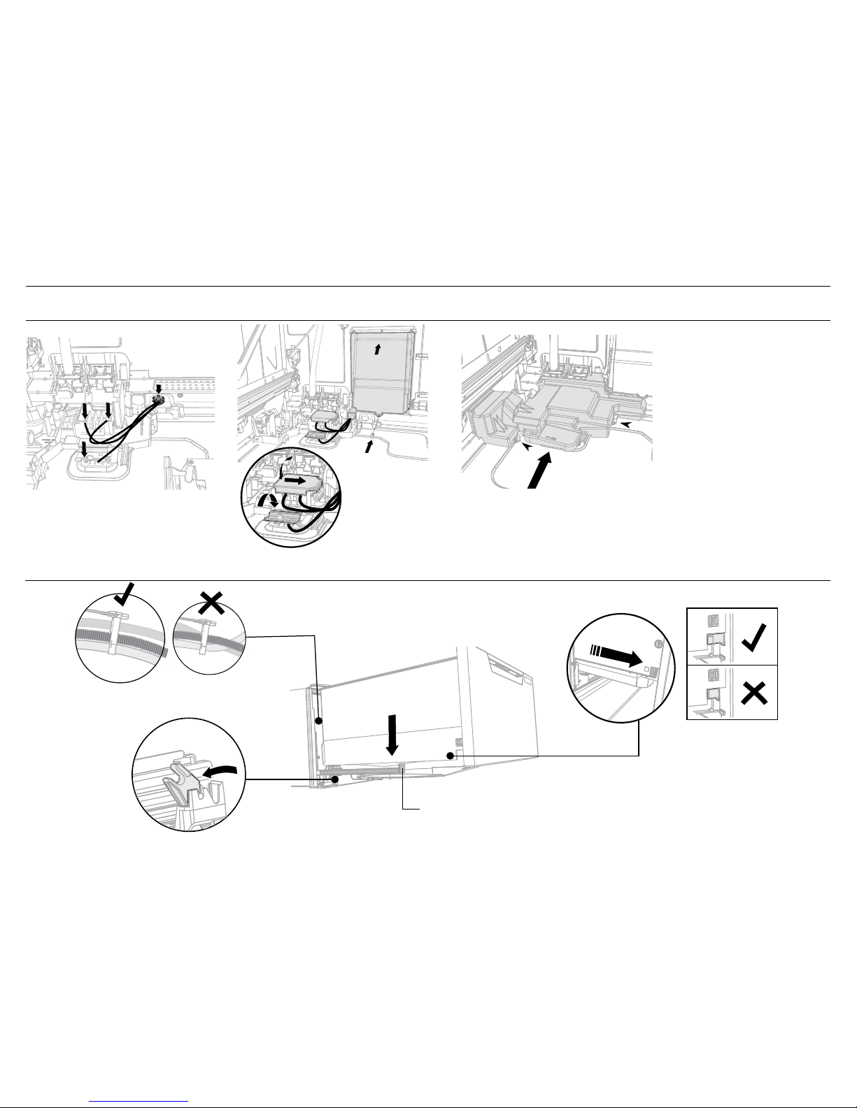
3 OPTIONALLY HARD WIRING PRIOR TO INSTALLATION
IMPORTANT!
Ensure the mains wires are routed
UNDERNEATH all other harness
wiring from the electronics module.
3-D REFIT THE DRAWER ONTO THE RUNNERS & CLOSE
3-C TERMINATE MAINS WIRING AS SHOWN AND REPLACE MODULE AND COVERS
4” (100 mm)
Pull the release tabs forward on both
sides 4” (100 mm). Ensure the tabs are
fully pulled forward and click into place.
8
9
10
11
12
13
14
8 Fit a suitable cable clamp for the
conduit through the metal knockout.
Ensure wiring is routed through or
under under housing ribs.
9 Screw down the Live, Neutral and
Earth wires correctly.
10 Push the plastic harness cover back
over. It should clip back into place
11 Fold down and slide back the
terminal block cover.
12 Refit the electronics module back
into position, being careful of wiring.
13 Replace the screw securing the
electronics module.
14 Slide the access cover back,
ensuring the 2 clips shown are fully
locked in place.
NOTE: Use copper conductors
only.
1
2
3
4
Before refitting the
drawer, ensure the hoses
are not twisted and the
latches at the rear of
each drawer runner are
facing forward.
Lift or rotate anti-clockwise the
drawer back onto the drawer runners
on either side.
Release tab
5
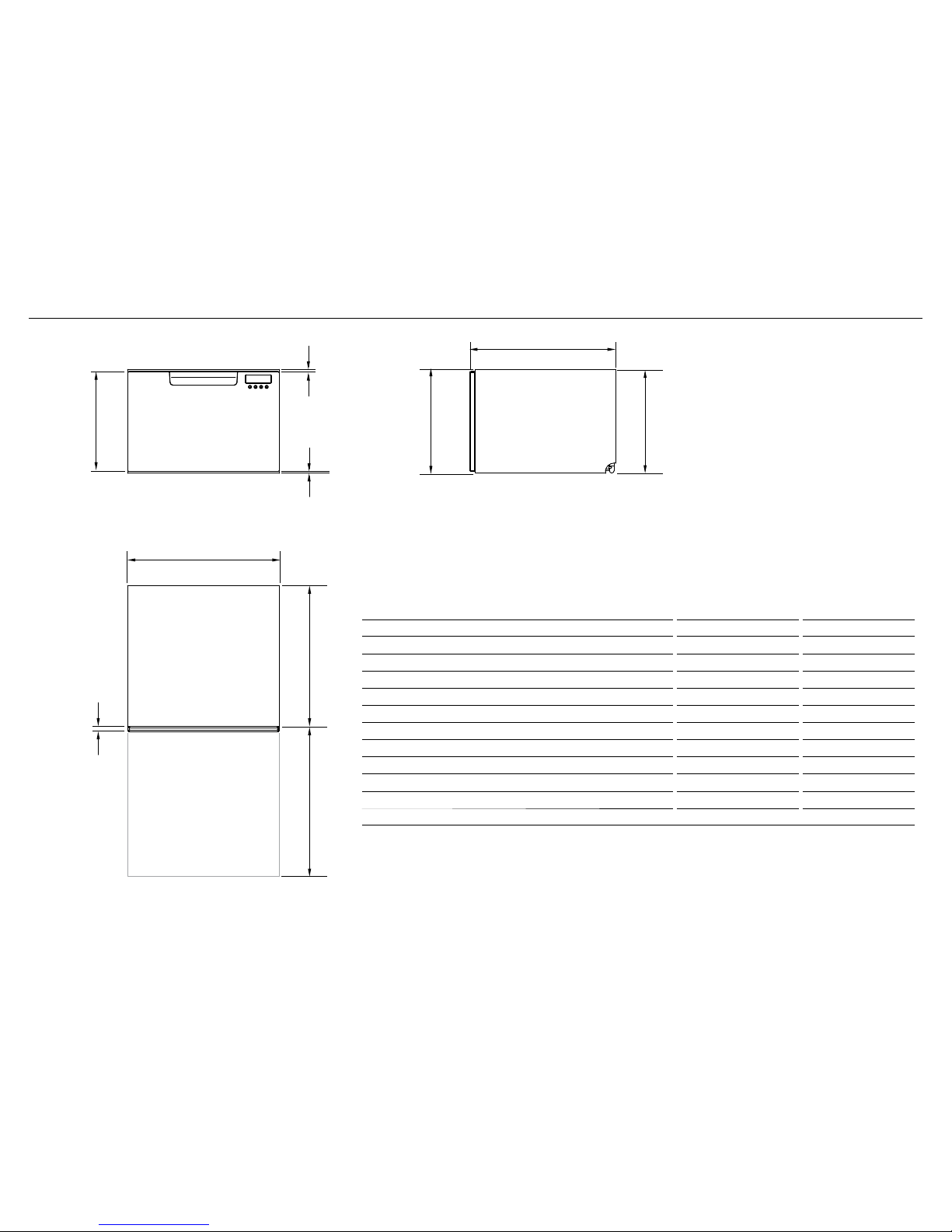
4 PRODUCT DIMENSIONS
DD24SA DD24SCT
PRODUCT DIMENSIONS INCHES (MM) INCHES (MM)
A
Overall height of product
1
16 1/8” (410) 17 7/8” (454)
B
Overall width of product
23 9/16” (599) 23 9/16” (599)
C
Overall depth of product
22 9/16” (573) 22 9/16” (573)
D
Depth of chassis (to back of front drawer panel)
21 3/4” (553) 21 3/4” (553)
E
Depth of drawer front panel
13/16” (20) 13/16” (20)
F
Height of drawer front panel
15 1/2” (393) 17 3/16” (437)
G
Height of chassis
1
16 1/8” (410) 17 7/8” (454)
H
Height from top of drawer front panel to top of chassis
5/16” (8) 5/16” (8)
I
Ventilation gap below drawer front panel
1/4” (7) 1/4” (7)
J
Maximum extension of drawer
21 9/16” (547) 21 9/16” (547)
1
includes 1/16” (2mm) high bracket slots
D
J
G
H
I
E
B
F
C
A
PLAN
PROFILE
FRONT
 Loading...