

Fisher & Paykel ACTIVESMART RS9120W Series, ACTIVESMART RS9120WRJ, ACTIVESMART RS9120WLJ Installation Manual

ACTIVESMART™ INTEGRATED
REFRIGERATOR FREEZER
RS9120W models
INSTALLATION GUIDE
NZ AU GB IE HK SG IN


CONTENTS
SAFETY AND WARNINGS
1
COMPONENTS
2
TOOLS
3
APPLIANCE AND CAVITY DIMENSIONS
4
CABINETRY OPTIONS
5
STAINLESS STEEL DOOR PANEL AND TOE KICK DIMENSIONS
6
CUSTOM DOOR PANEL AND TOE KICK DIMENSIONS
7
CUSTOM DOOR PANEL INSTALLATION DIMENSIONS
8
CUSTOM DOOR PANEL INSTALLATION TEMPLATE
9
DOOR CLEARANCE
!0
ELECTRICAL AND PLUMBING
!1
BEFORE INSTALLATION
!2
CAVITY PREPARATION
!3
WATER AND POWER SUPPLY CONNECTION
!4
TOP TRIM INSTALLATION
!5
SIDE BRACKET INSTALLATION
!6
POSITIONING INTO CABINETRY
!7
ALIGNING INSIDE CABINETRY
!8
DOOR PANEL INSTALLATION — STAINLESS STEEL
!9
@2
DOOR AND DRAWER TRIMS INSTALLATION
@4
CABINET TRIMS INSTALLATION — [A] FLEXIBLE SPRING CLIP METHOD
@5
FIXING TO CABINETRY
@1
WATER FILTER INSTALLATION
TOE KICK INSTALLATION
@3
FINAL CHECKLIST
@7
OR
OR
DOOR PANEL INSTALLATION — CUSTOM
@0
CABINET TRIMS INSTALLATION — [B] FIXED SCREW METHOD
@6
IMPORTANT!
SAVE THESE INSTRUCTIONS
The models shown in this installation guide may not be available in all markets and are subject to change at any time. For current details about model and specification availability in your country,
go to our website fisherpaykel.com or contact your local Fisher & Paykel dealer.
1

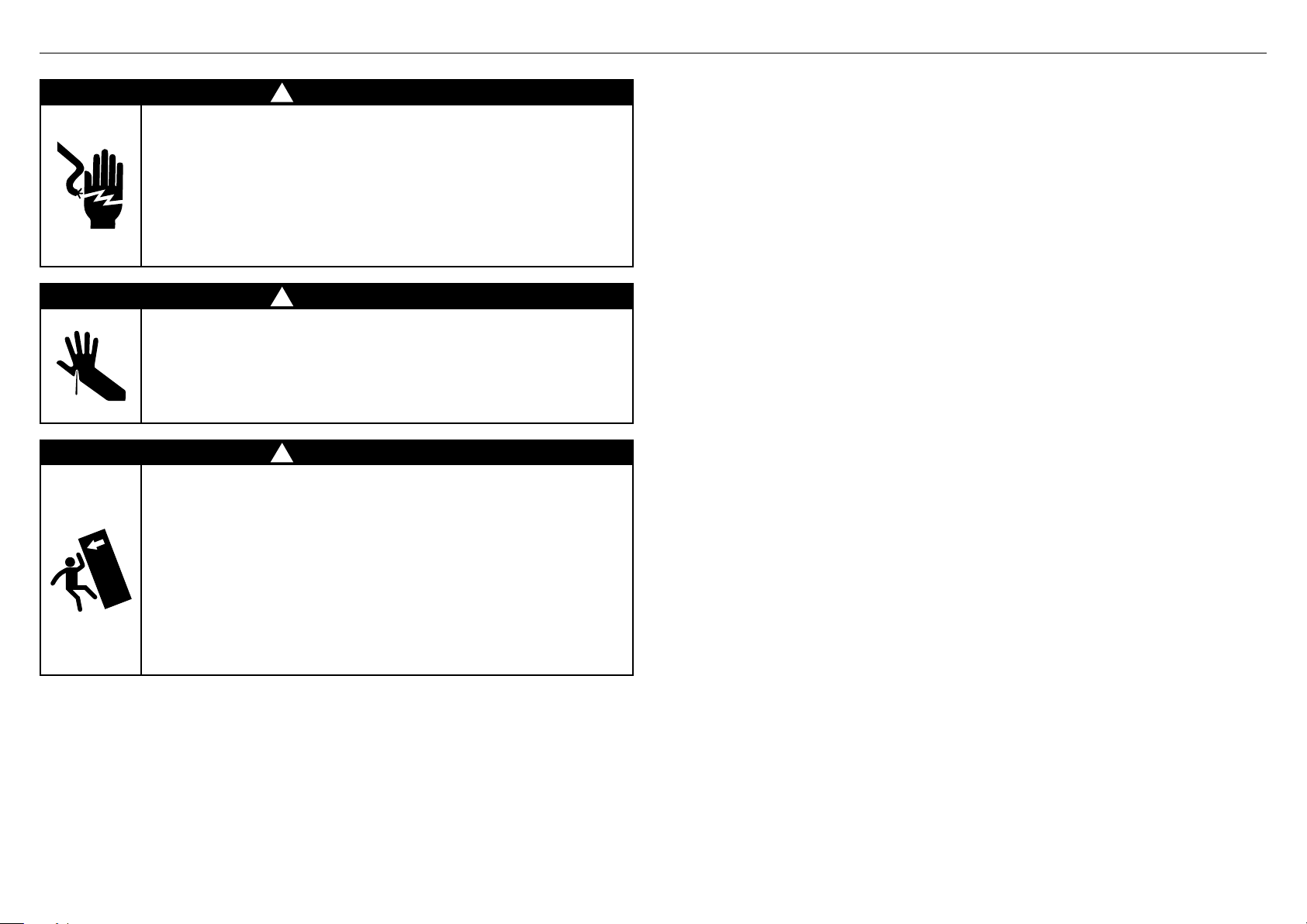
1 SAFETY AND WARNINGS
!
WARNING!
Electric Shock Hazard
Read and follow the safety and warnings
outlined in this installation guide before
operating this appliance.
Failure to do so can result in death,
electricshock, fire or injury topersons.
!
WARNING!
Cut Hazard
Take care — panel edges are sharp.
Failure to use caution could result in injury
or cuts.
!
WARNING!
This appliance is top-heavy and must
be secured to prevent the possibility of
tippingforward.
To ensure that the appliance is stable under
allloading conditions, theanti-tip bracket
and fittings supplied must be installed
according tothe following installation
instructions by aprofessional installer.
IMPORTANT!
●
It is very important for the installer to follow the instructions in this installation guide
to ensure proper installation and operation of the appliance. Ensure that you read the
installation guide thoroughly and understand all information.
●
The water connection to your Ice and water appliance must be installed by an
authorized plumber or Fisher & Paykel trained and supported service technician
andcomply with all state and local laws.
●
Installation and use MUST comply with all state and local plumbing codes.
Checkwithyour local public works department for plumbing codes.
Youmustfollowtheir guidelines as you install the water filtration system.
●
To avoid serious illness or death, only connect your water filter to safe drinking water.
●
The water filter cartridge needs to be changed when the replacement indicator icon
illuminates. This will happen every 6 months.
●
If the water filtration system has been allowed to freeze, replace filter cartridge.
Failureto replace the disposable filter at recommended intervals may lead to reduced
filter performance and failure of the filter, causing property damage from water
leakageor flooding.
●
In cases of excessively reduced filter life — we recommend that you consult a local
plumber or your water supplier for advice on suitable filtration requirements for the
water supplied to your home.
●
Filter replacement is the consumer’s responsibility and will not be covered by the
warranty except in the case of faulty parts or materials within the filter cartridge.
●
If the water has not created ice for some time or ice has an unpleasant taste or odor
dispose of ice and refer to the flushing instructions detailed in the installation section
of this user guide / installation guide. If unpleasant taste or odor persists, you may
wishto fit a new filter cartridge.
●
Use new tubing supplied with the appliance. DO NOT reuse old tubing from old water
and ice connections.
●
Your water filtration system can withstand up to 120psi (827kPa) of water pressure.
Ensure the supplied pressure reducing valve is installed before installing the water
filtration system. DO NOT install if water pressure exceeds 120psi (827kPa).
To reduce the risk associated with property damage due to water leakage or flooding:
●
DO NOT install systems in areas where ambient temperatures may go above 38°C or
drop below 0.6°C.
●
DO NOT install on hot water supply lines. The maximum operating water temperature
of this filter system is 38°C.
●
DO NOT install where water hammer conditions may occur. If water hammer
conditions exist, you must install a water hammer arrester.
WARNING!
To reduce the risk associated with choking:
●
DO NOT allow children under 3 years of age to have access to small parts during the
installation of the water filter.
3
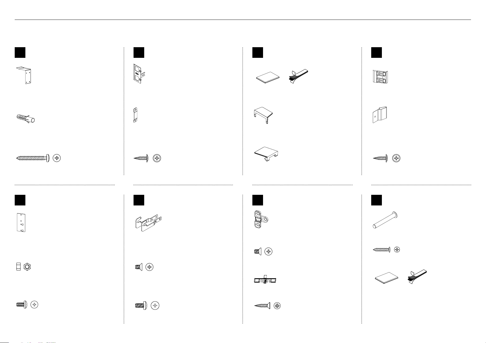
Internal box (Installation kit)
Located inside the appliance
2 COMPONENTS
Anti-tip bracket
A
assemblykit
Anti-tip bracket
(1)
Masonry plug
(4)
#10x40 cross-head screw
(4)
Top trim
E
install kit
Door panel
B
attachmentkit
Side bracket
(10)
Side strap
(10)
8x16 mush washer screw
(36)
Side bracket
F
install kit
Door / drawer trim
C
installkit
Dual adhesive tabs
(12)
Side cover
(2)
Top cover
(4)
G
Fixing bracket
install kit
Cabinet side trim
D
installkit
Side trim bracket
(6)
Spring clip
(6)
8x16 mush washer screw
(12)
Miscellaneous
Z
components
Cabinet top trim bracket
(2)
M5 nut
(4)
M5x8 cross-head screw
(4)
4
Side base brackets (right/left)
(2)
M5x8 countersunk cross-head screw
(4)
M5x10 cross-head screw
(10)
Fixing bracket
(4)
M5x8 countersunk cross-head screw
(8)
Screw cover
(4)
8x19 twin thread screw
(8)
Hinge limiting pin
(1)
8x16 panhead screw
(3)
Dual adhesive tabs
(6)
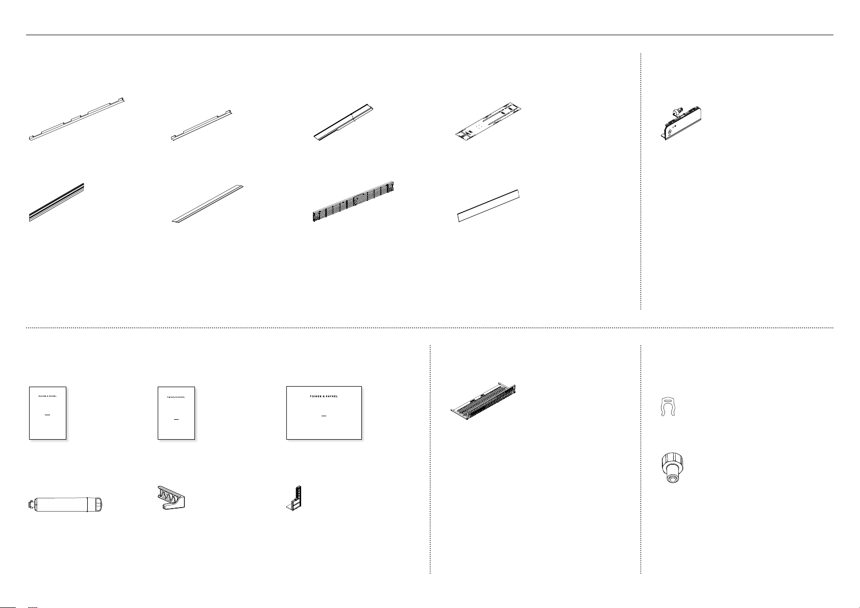
2 COMPONENTS
External box
Located at back panel of appliance
Door side trim
(2)
Top trim
(1)
Miscellaneous items pack
Located inside the appliance
Drawer side trim
(2)
Drawer top trim
(1)
Cabinet side trim
(2)
Top grille
(1)
Double-sided door panel template
(1)
Toe kick
(1)
Toe kick filter
Located inside the appliance
Ice and Water display
(Ice and Water models only)
Located inside the appliance
External display module
(1)
Water fittings kit
(Ice and Water models only)
Located inside the appliance
ACTIVESMART™
INTEGRATED REFRIGERATOR
RS90A, RS9120W,
RS36A72, RS36A80 & RS36W80 models
USER GUIDE
NZ AU GB IE HK SG IN US
User guide
(1)
Water filter
(1)
SERVICE & WARRANTY
SERVICE ET GARANTIE
ΣΈΡΒΙΣ ΚΑΙ ΕΓΓΎΗΣΗ
SERVIZIO E GARANZIA
SERVICE & GARANTIE
HUOLTO JA TAKUU
SERVICE OG GARANTI
保修和维修
服務和保修
Service and Warranty
(1)
Filter cartridge tool
(1)
ACTIVESMART™ INTEGRATED
SINGLE DOOR / DRAWER REFRIGERATOR
RS9120W models
INSTALLATION GUIDE
NZ AU GB IE HK SG IN
846806D 02.19
Installation guide
(1)
Air flow divider
(1)
Toe kick filter
(1)
Collet locking clip
(1)
Water tap adaptor
(1)
5
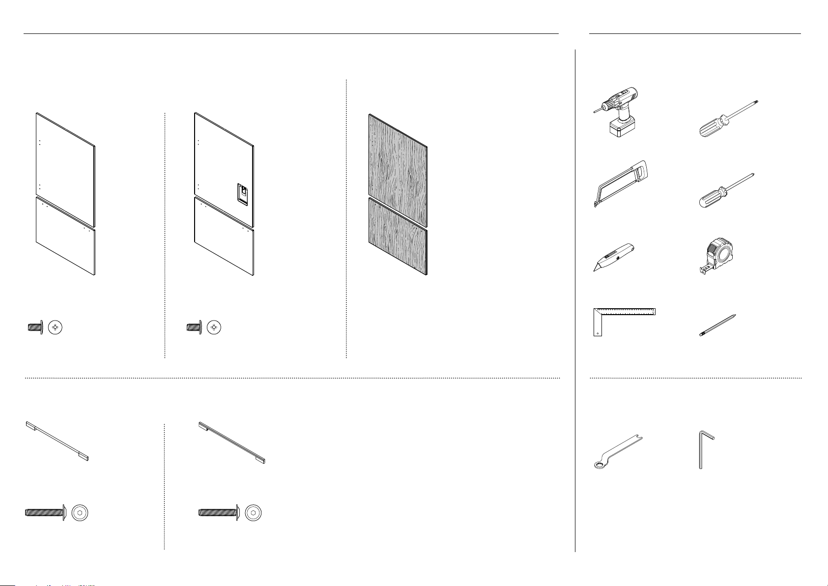
2 COMPONENTS 3 TOOLS
Door panel set
Not supplied and must be purchased separately
Stainless steel (Fisher & Paykel) door panel set:
Includes 1x single door panel and 1x drawer panel.
Non-water dispensing door panel set
(RD9120W / RD9121W)
Ice and Water door panel set
( RD9120WRU / RD9121WRU)
Required tools
Not included with appliance
Custom door panel set:
Supplied by customer to match their cabinetry.
Applicable for Non-water dispensing models only.
Powered driver Torx screwdriver
Hacksaw Cross-head screwdriver
Cutter Measuring tape
M5x14 mush cross-head (SS) screw
(24)
M5x14 mush cross-head (SS) screw
(24)
Door handle kit
Not supplied and must be purchased separately. Select between the options below:
Contemporary round
door handle (2)
M5x25 pan head socket
screw (8)
Contemporary square
door handle (2)
M5x25 pan head socket
screw (8)
6
Ruler Pencil
Supplied tools
Included in internal box
FPA spanner
(1)
Hex key
(1)
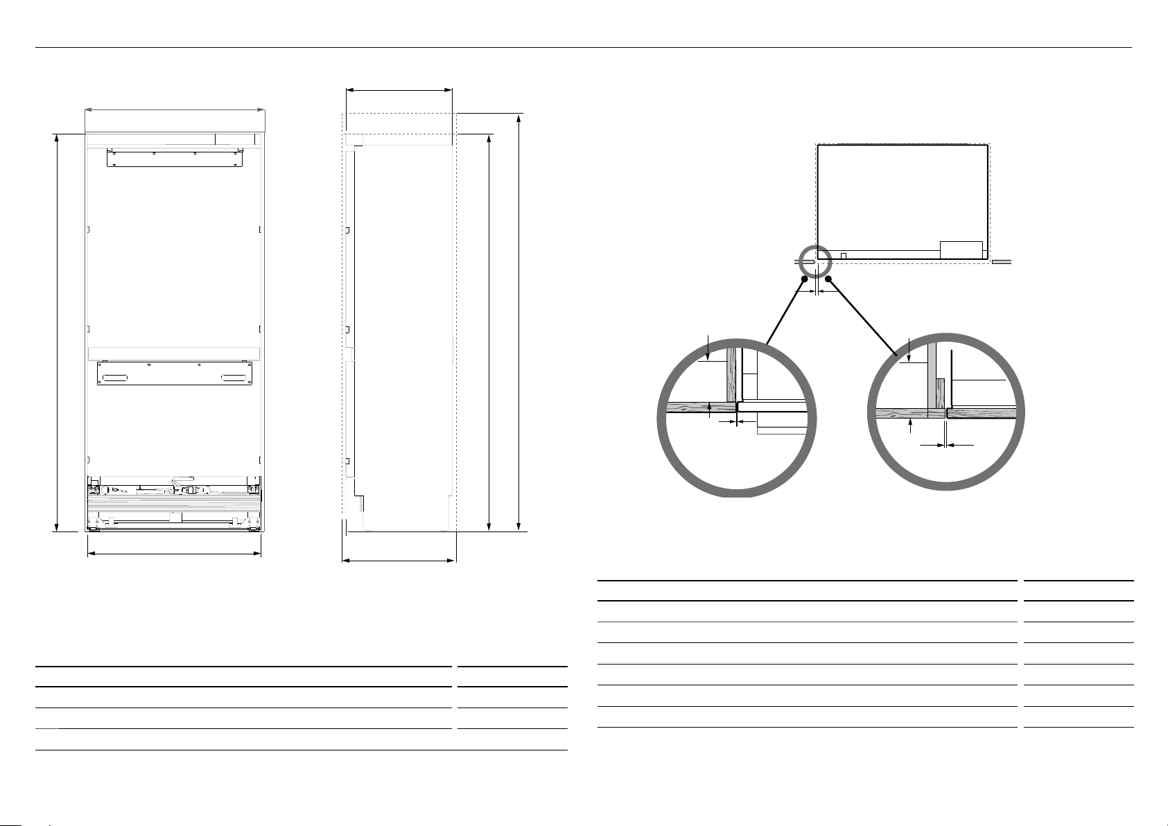
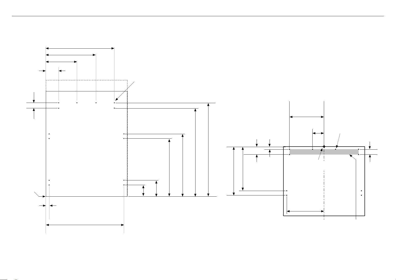
4 APPLIANCE AND CAVITY DIMENSIONS
A
f
c
d
e
IMPORTANT!
For ease of installation, ensure cavity width is consistent
top to bottom and height isconsistent left to right.
H
I
PLAN VIEW
I
H
H
b
APPLIANCE DIMENSIONS mm
Overall height of appliance* 2028
A
Overall width of appliance 890
B
Overall depth of appliance (without door panels) 606
c
* includes mounted feet
g
PROFILE VIEWFRONT VIEW
Frameless: Finished return top and sides
CAVITY DIMENSIONS mm
Overall height of cavity (for refrigerator using RD9120 door panel set) 2032
D
Overall height of cavity (for refrigerator using RD9121 door panel set) 2134
e
Overall width of cavity 914
f
Overall depth of cavity 635
g
Minimum cabinetry gap clearance from edge of door panels 4
H
Minimum required finished return (side and top cavity)* min. 89
I
NOTE: Supplied top trim enables cavity height to be either 2032mm or 2134mm.
* Assumes a door panel thickness of 19mm.
Flush install
Framed: Finished return top and sides
Flush install
7
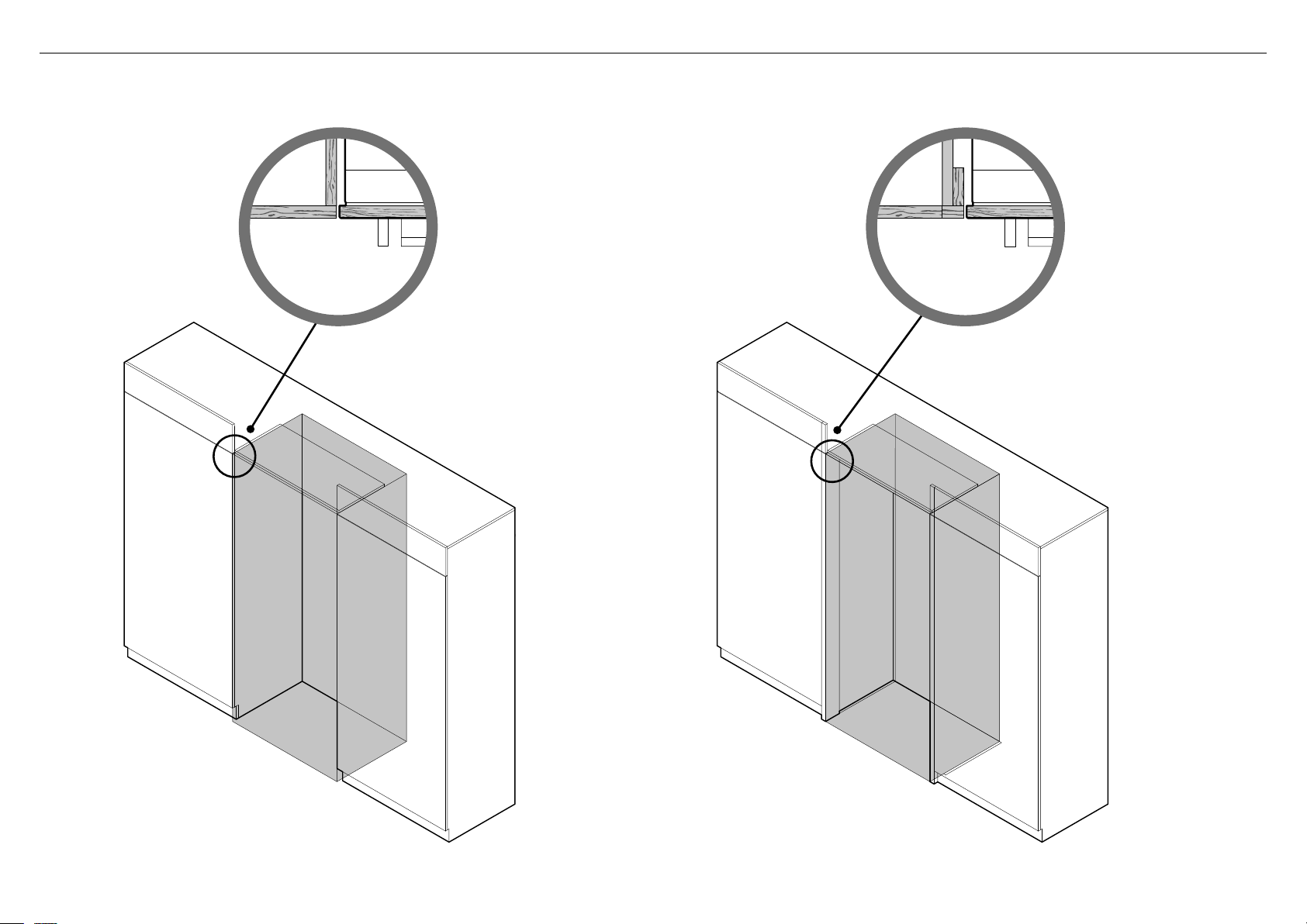
5 CABINETRY OPTIONS
FRAMELESS CABINETRY
(Aligns the appliance with the cabinetry)
FRAMED CABINETRY
(Aligns the appliance with the frame of the cabinetry)
Note: Drawings are only for reference and not the actual cavity width of the cabinetry.
8
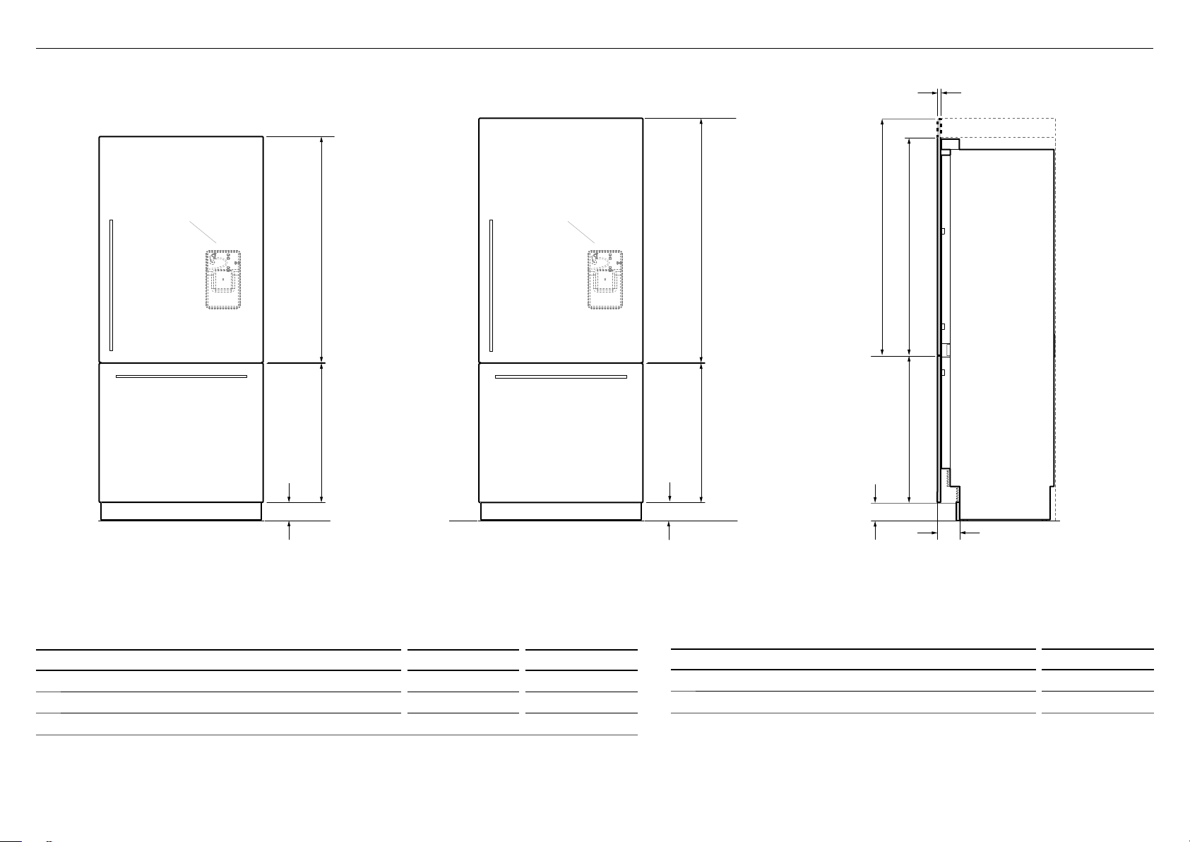
6 STAINLESS STEEL DOOR PANEL AND TOE KICK DIMENSIONS
c
Available on
Ice and Water
models only
DOOR PANEL SET
RD9120W / RD9120WRU
D
a
b
Available on
Ice and Water
models only
DOOR PANEL SET
RD9121W / RD9121WRU
D
a
b
a
b
d
e
RD9120W /
RD9120WRU
DOOR PANEL SETS DIMENSIONS mm mm
Height of top door panel 1150 1252
a
Height of bottom drawer panel 772 772
b
Depth of appliance front panels (excluding handles) 19 19
c
Note:
●
Optional Fisher & Paykel Stainless steel front panels. Model no. RD9120W / RD9121W (Non-water dispensing model)
andmodel no. RD9120 WRU/ RD9121WRU (Ice and Water model).
RD9121W /
RD9121WRU
TOE KICK PANEL DIMENSIONS mm
Height of toe kick panel 102
d
Depth of toe kick (measured from front of door panels) 120
e
Note:
●
Stainless steel toe kick, height 102mm is supplied with the appliance.
●
Customers need to supply their own custom toe kick, height 102 – 152mm.
●
For toe kick greater than 102mm, shorten the height of the bottom grille accordingly.
Refer to 'Toe kick installation' for more information.
9
CUSTOM PANEL DIMENSIONS
Note: Top trim supplied for
84" installation
f
D
A
B
c
e
A
d
e
g
c
IMPORTANT!
Custom door / drawer panels are
applicable for Non-water dispensing
models only.
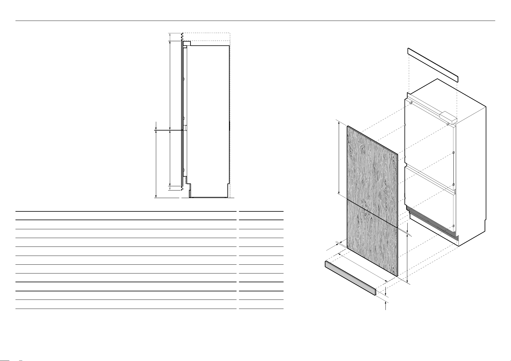
7 CUSTOM DOOR PANEL AND TOE KICK DIMENSIONS
Note: Top trim supplied
for 2134mm installation
A
e
c
d
PROFILE VIEW
CUSTOM PANEL DIMENSIONS mm
Height of top door panel 1150 – 1252
A
Width of top door and bottom drawer panel 906
B
Height of bottom drawer panel 722 – 772
C
Height from bottom of appliance to top of bottom drawerpanel 874
D
Gap between top door panel and bottom drawer panel 4
E
Height of toe kick panel* 102 – 152
F
Depth of custom panels 16 – 25
G
DOOR PANEL WEIGHT
Maximum weight of top door panel
Maximum weight of bottom drawer panel
*
Custom toe kick should be designed at 102 – 152mm relative to door / drawer panel height.
Note:
●
Custom door panels and toe kick must be supplied by the customer.
●
For toe kick greater than 102mm, shorten the height of the bottom grille accordingly. Refer to 'Toe kick installation' for more information.
(with handles) 20
(with handles) 11
ISO VIEW
kg
10
8 CUSTOM DOOR PANEL INSTALLATION DIMENSIONS
The drawings below apply to Non-water dispensing models only (RS9120WRJ and RS9120WLJ). Dimensions apply for the preparation and installation of custom door panels.
For Dwg and Dxf files of the below panel preparation download the folder on thekitchentools.fisherpaykel.com.
764mm
558mm
347mm
141mm
Ø2mm REF
14x Pilot holes recommended for bracket attachment.
(Do not penetrate front surface).
385mm
Ø 2mm REF
10x Pilot holes recommended
for bracket attachment.
(Do not penetrate front surface).
58.1mm
Ensure handle is mounted
65mm from edge of panel
to the center — this will avoid
interference with bracket.
129mm
29mm
All measurements
to be made from
bottom left corner
37mm
869mm
TOP PANEL — REAR VIEW
126mm
176mm
634mm
684mm
957.9mm
1016mm
542mm
87mm
All measurements to be made
from top and centerline.
492mm
416mm
Cutouts are located in attachment bracket for Fisher & Paykel handle only.
Iflocatingcustom handle in the shaded area shown above, ensure handle screw
headsare countersunk into back of panel to avoid interference with hanging bracket.
BOTTOM PANEL — REAR VIEW
58.1mm
11
9 CUSTOM DOOR PANEL INSTALLATION TEMPLATE
DRAWER PANEL TOP EDGE
DRAWER PANEL
TEMPLATE
849548
DRAWER PANEL LEFT SIDE
DRAWER PANEL RIGHT SIDE
HANGING BRACKET HOLES
HANGING BRACKET HOLES
DRAWER PANEL LEFT SIDE
DRAWER PANEL RIGHT SIDE
HANGING BRACKET HOLES
HANGING BRACKET HOLES
DOOR PANEL BOTTOM EDGE
DOOR PANEL LEFT SIDE
DOOR PANEL RIGHT SIDE
SIDE BRACKET HOLES
SIDE BRACKET HOLES
DOOR PANEL
TEMPLATE
849548
DOOR PANEL LEFT SIDE
DOOR PANEL RIGHT SIDE
SIDE BRACKET HOLES
SIDE BRACKET HOLES
DOOR PANEL LEFT SIDE
DOOR PANEL LEFT SIDE
HANGING BRACKET HOLES
DOOR PANEL RIGHT SIDE
HANGING BRACKET HOLES
DOOR PANEL RIGHT SIDE
PRINT SPECIFICATION REVISIONS
DRWN DATE CHKD ECN REV
BJ 04/04/19 1
1
862945
GRAPHICS RS9120 DOOR TEMPLATETITLE:
DRAWN: DATE:
SCALE: 1:1
FISHER & PAYKEL APPLIANCES LIMITED
GRAPHICS NO:
REVISION:
BINIL JOSE
04/04/2019
400mm
This template is a single double-sided sheet used as
a guide to drill screw holes for installing your Custom
door and drawer panels. The actual template is
included with this installation guide.
Refer to 'Door panel installation — Custom' (page 30)
for more information.
DRAWER PANEL TOP EDGE
DRAWER PANEL LEFT SIDE
DRAWER PANEL
DRAWER PANEL LEFT SIDE
HANGING BRACKET HOLES
HANGING BRACKET HOLES
HANGING BRACKET HOLES
TEMPLATE
849548
HANGING BRACKET HOLES
DRAWER PANEL RIGHT SIDE
DRAWER PANEL RIGHT SIDE
DOOR PANEL RIGHT SIDE
DOOR PANEL LEFT SIDE
HANGING BRACKET HOLES
DOOR PANEL RIGHT SIDE
SIDE BRACKET HOLES
DOOR PANEL RIGHT SIDE
HANGING BRACKET HOLES
SIDE BRACKET HOLES
DOOR PANEL LEFT SIDE
DOOR PANEL LEFT SIDE
12
DOOR PANEL
LEFT DOOR
PANEL SIDE
TEMPLATE
849548
SIDE BRACKET HOLES
DOOR PANEL RIGHT SIDE
DOOR PANEL BOTTOM EDGE
RIGHT DOOR
PANEL SIDE
SIDE BRACKET HOLES
DOOR PANEL LEFT SIDE
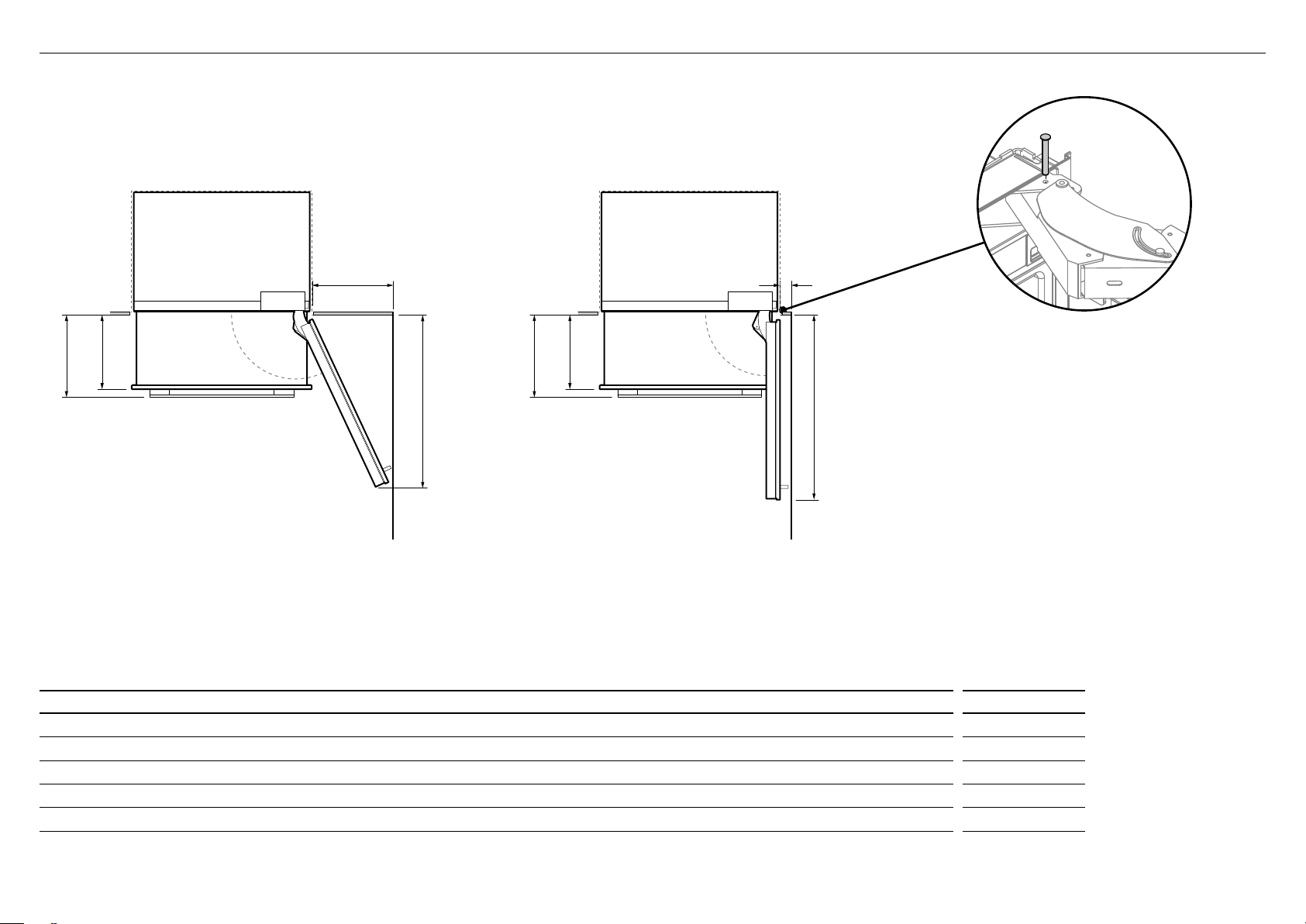
!0 DOOR CLEARANCE
DOOR OPENING & CLEARANCE DIMENSIONS
d
b
c
b
c
A
115° DOOR OPENING
(FULL INTERNAL ACCESS)
Wall
DOOR CLEARANCE DIMENSIONS mm
Depth of door (widest opening) measured from front of door 940
A
Depth of drawer (open) measured from front of drawer, including handle 400
B
Depth of drawer (open) measured from front of drawer, excluding handle 360
c
Minimum door clearance* to adjacent wall (115° — full internal access) 410
d
Minimum door clearance* to adjacent wall (90° — reduced internal access) 110
e
90° DOOR OPENING
e
a
Insert hinge limiting pin
WARNING!
●
Before opening the doors, ensure that the appliance is
stable.
●
Follow these steps to avoid risks that can cause serious
injury or death.
For 90° door swing, a hinge limiting pin is supplied with
your appliance. This pin fits in the boreholes of the top
hinge.
Open door to 90°.
1
Insert the hinge limiting pin vertically into the bore hole.
2
– Apply a gentle tap to the pin if it does not slide
smoothly.
* Measured from front cabinetry edge.
13
 Loading...