

Fisher & Paykel ACTIVESMART RS9120WRJ, ACTIVESMART RS9120WLJ, ACTIVESMART RS9120WRU Installation Manual

ACTIVESMART™
INTEGRATED REFRIGERATOR
RS9120W Models
FRAMELESS CABINETRY
INSTALLATION GUIDE
NZ AU GB IE HK SG IN
846806 A 07.17

1
FOLLOW THE INSTALLATION SEQUENCE RELEVANT TO YOUR CABINETRY
FISHER & PAYKEL: RS9120W(R/L)J AND RS9120WRU models
NOTE: PRODUCT IS DESIGNED FOR INTEGRATED INSTALLATION ONLY
FRAMED CABINETRY
(Framed: Aligns the refrigerator with the frame of the cabinetry)
(refer to the flip side of the booklet)
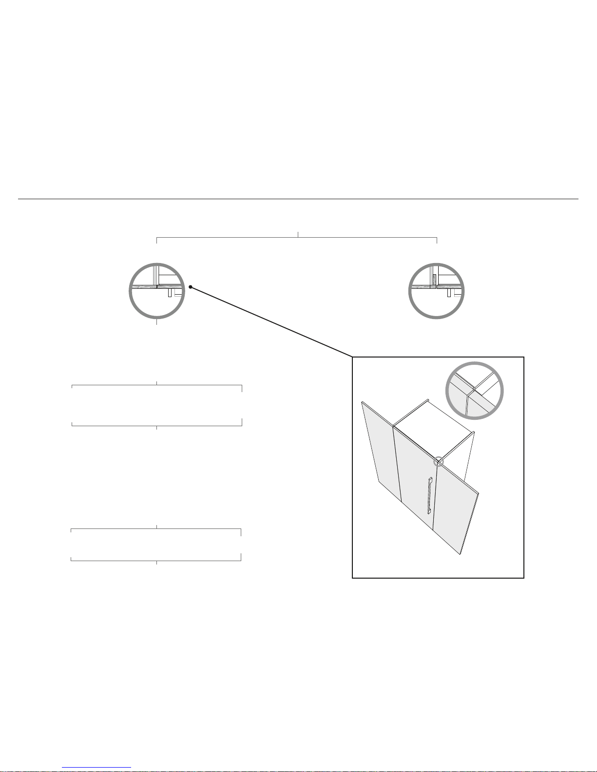
FRAMELESS CABINETRY
(Frameless: Aligns the refrigerator with the cabinetry)
Note: shown with custom panel
and handles attached to fridge
Note: shown with custom panel
and handles attached to fridge
FRAMELESS CABINETRY
This booklet describes the installation process for frameless cabinetry
(for framed cabinetry please refer to flip side of booklet).
1 SAFETY AND WARNINGS
2 BEFORE INSTALLATION
3 COMPONENTS LIST
4 PRODUCT AND CAVITY DIMENSIONS
5 CUSTOM DOOR PANEL DIMENSIONS
6 CAVITY PREPARATIONS
7 MAXIMUM DISTANCE OF HOSE AND POWER CORD
OR
8 2032mm HEIGHT CAVITY
ATTACH ANTI-TIP BRACKET
8 2134mm HEIGHT CAVITY
ATTACH ANTI-TIP BRACKET
ATTACH TOP TRIM
9
ATTACH SIDE BASE BRACKETS AND DOOR STUDS
!0 CONNECT TO WATER AND ELECTRICAL SUPPLY
!1 PRE-ALIGN YOUR PRODUCT INSIDE CABINETRY
!2 INSTALL WATER FILTER CARTRIDGE AND KICKSTRIPS
!3 ASSEMBLE DOOR PANEL SET
!4 HANG WATER DISPENSING DOOR PANEL
!5 HANG NON-WATER DISPENSING DOOR PANELS
!6 ICE AND WATER INITIATION
!7 ATTACH FIXING BRACKETS
!8 ATTACH COVERS
!9 ATTACH TOE KICK
@0 ATTACH BOTTOM KICKSTRIP
@2 ADJUST HINGE TENSIONING SCREWS
@3 FINAL CHECKLIST
OR
@1 ATTACH SIDE TRIM BRACKETS –
(B) FIXED SCREW METHOD
@1 ATTACH SIDE TRIM BRACKETS –
(A) FLEXIBLE SPRING CLIP METHOD
(Recommended method)

3
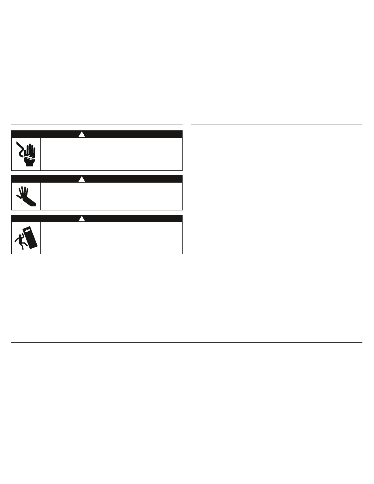
1 SAFETY AND WARNINGS
!
WARNING!
Electric Shock Hazard
Read and follow the safety and warnings outlined in this installation
guide before operating this appliance.
Failure to do so can result in death, electric shock, fire or injury
topersons.
!
WARNING!
Cut Hazard
Take care – panel edges are sharp. Failure to use caution could result in
injury or cuts.
!
WARNING!
This appliance is top-heavy and must be secured to prevent the
possibility of tippingforward.
To ensure that the appliance is stable under all loading conditions,
theanti-tip bracket and fittings supplied must be installed according
tothe following installation instructions by a professional installer.
IMPORTANT!
SAVE THESE INSTRUCTIONS
The models shown in this installation guide may not be available in all markets and are subject to change at any time. For current details about model and specification availability in your country, please go to
our website www.fisherpaykel.com or contact your local Fisher & Paykel dealer.
2 BEFORE INSTALLATION
Please follow the installation steps specified to ensure your appliance is installed and
operatescorrectly.
Refrigeration alcove preparation
For integrated installation, a finished return of solid material is required across the top and
sides of the new or existing alcove.
It is recommended that the return be at least 88.9mm deep across the sides.
Refer to page13 prior to installation of the refrigerator.
Power
Connect your refrigerator to its own power point.
– Avoid sharing the power point with other appliances to prevent accidental switching
off of the refrigerator.
For power requirements, please refer to the information on the serial plate. This is located
atthe front right-hand side of the drawer when open.
Ensure your refrigerator is properly grounded (earthed).
Connect the refrigerator to an electrical supply 220V–240V, 50Hz with the fitted plug and lead.
Follow the National Electrical Code and all local codes and ordinances when installing
thisrefrigerator.
Location
Do not place your refrigerator in direct sunlight or beside any heat generating appliance
egcooktop, oven or dishwasher.
Your refrigerator has front and rear rollers for moving the refrigerator forward and backward.
Do not move the refrigerator sideways to avoid damaging the rollers or the floor covering/
surface.
Plumbing
Your refrigerator must be installed by a qualified appliance installer as incorrect plumbing
can lead to water leaks.
Fisher & Paykel Appliances does not accept responsibility for damage (including water
damage) caused by faulty installation or plumbing.
Door panel set
The standard appliance does not include a door panel set.
Custom door panels can only be used with Automatic ice dispensing models.
For a custom integrated design on Automatic ice models, customers should supply their
own custom door panel set to match their cabinetry. All the hardware required to mount the
door panel sets to the refrigerator doors is supplied with the refrigerator.
Door panel sets are available through your Fisher & Paykel dealer.
– Fisher & Paykel door panel sets are available (EZKleen stainless steel door panels)
model numbers: RD9121W(L/R), RD9121WRU
Handle sets are optional for custom door panels and can also be purchased through your
Fisher & Paykel dealer.

4
3 COMPONENTS LIST
Door hanging bracket
(1)
Drawer hanging bracket
(1)
Side bracket
(6)
Side strap
(6)
M5x10 pan head
Phillips screw
(6)
Door panel fittings – Included with standard refrigerator.
M8 stud
(5)
M8 nut
(4)
M8 washer
(4)
Anti-tip bracket fittings – Included with standard refrigerator.
Anti-tip bracket
(1)
Masonry plug
(4)
#10x40 pan head
Phillips screw
(4)
#8 x 16 mush washer screw
(35)
((12) for Side trim attachment:
Fixed screw method only)
Locking bracket
(1)
5
3 COMPONENTS LIST
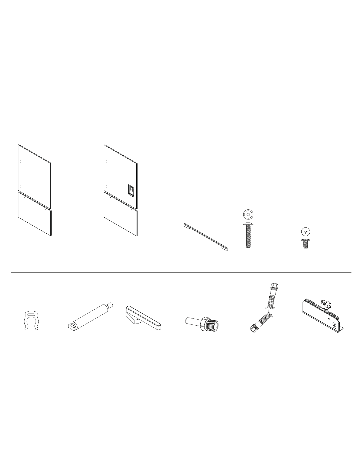
Optional accessories – The standard appliance does not include a door panel set.
Fisher & Paykel (EZKleen stainless steel) door panel sets are available. For models with a water dispenser, the stainless steel door panel sets are required.
For complete integration of Automatic ice models a custom door panel set is required. Door handle kits are available as an accessory for custom door panels.
M5x25 pan head
socket screw
(8)
Door panel set:
Ice & Water door panel (1)
Drawer panel (1)
Part numbers:
F&P: RD9121WRU
Door panel set:
Automatic ice dispensing door panel (1)
Drawer panel (1)
Part numbers:
F&P: RD9121W(L/R)
M5x14 Mush Phillips SS
(34)
Water filter cartridge (1)
Part number: 847200
Filter cartridge tool
(1)
Collet locking key
(1)
Water fittings – Included with the standard appliance.
6mm Adaptor
(1)
6mm comp.
Stainless Steel braided hose
(1)
F&P: Door handle (2)
External display module (1)
(included with water
dispensing refrigerator)
6
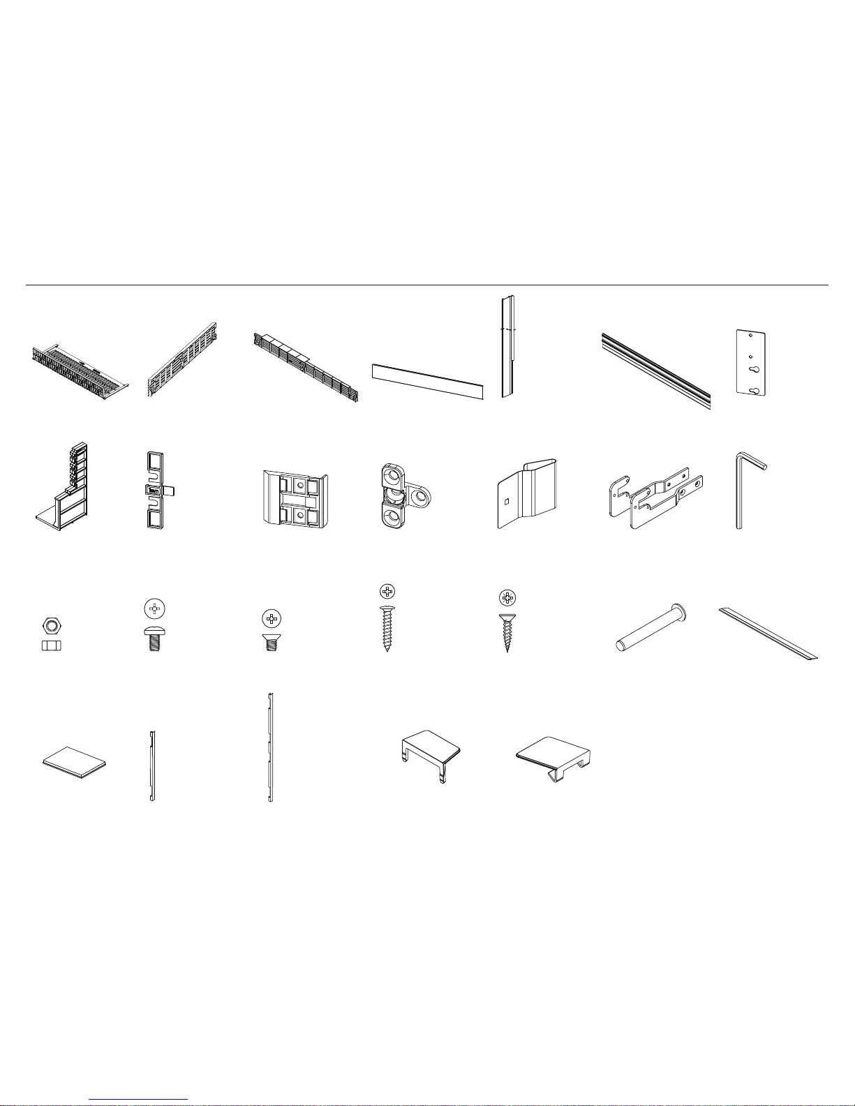
3 COMPONENTS LIST
Product hardware – Included with standard refrigerator.
Air divider
(1)
Screw cover
(4)
Cabinet top trim
joining bracket*
(2)
Spring Clip (6)
(for Cabinet side trim
attachment: Flexible
spring clip method only)
Cabinet side trim
bracket
(6)
Fixing bracket
(4)
Top kickstrip grille
(1)
Kickstrip filter
(1)
Bottom kickstrip grille
(1)
Cabinet side trim
(2)
M5 nut
(4)
M5 x 8 countersunk
Phillips screw
(12)
M5 x 8 pan head
Phillips screw
(4)
#8 x 19 twin thread screw
(8)
Side base bracket
(2)
Hinge limiting pin
(1)
Allen key
(1)
#8 x 16mm
panhead screw
(3)
Stainless steel toe kick
(1)
* To be used when finished enclosure is 2134mm.
3M Dual Lock™ tabs
(10)
Drawer top trim
(1)
Drawer side trim
(2)
Door side trim
(2)
Side cover
(4)
Top cover
(2)
Cabinet top trim*
(1)
7
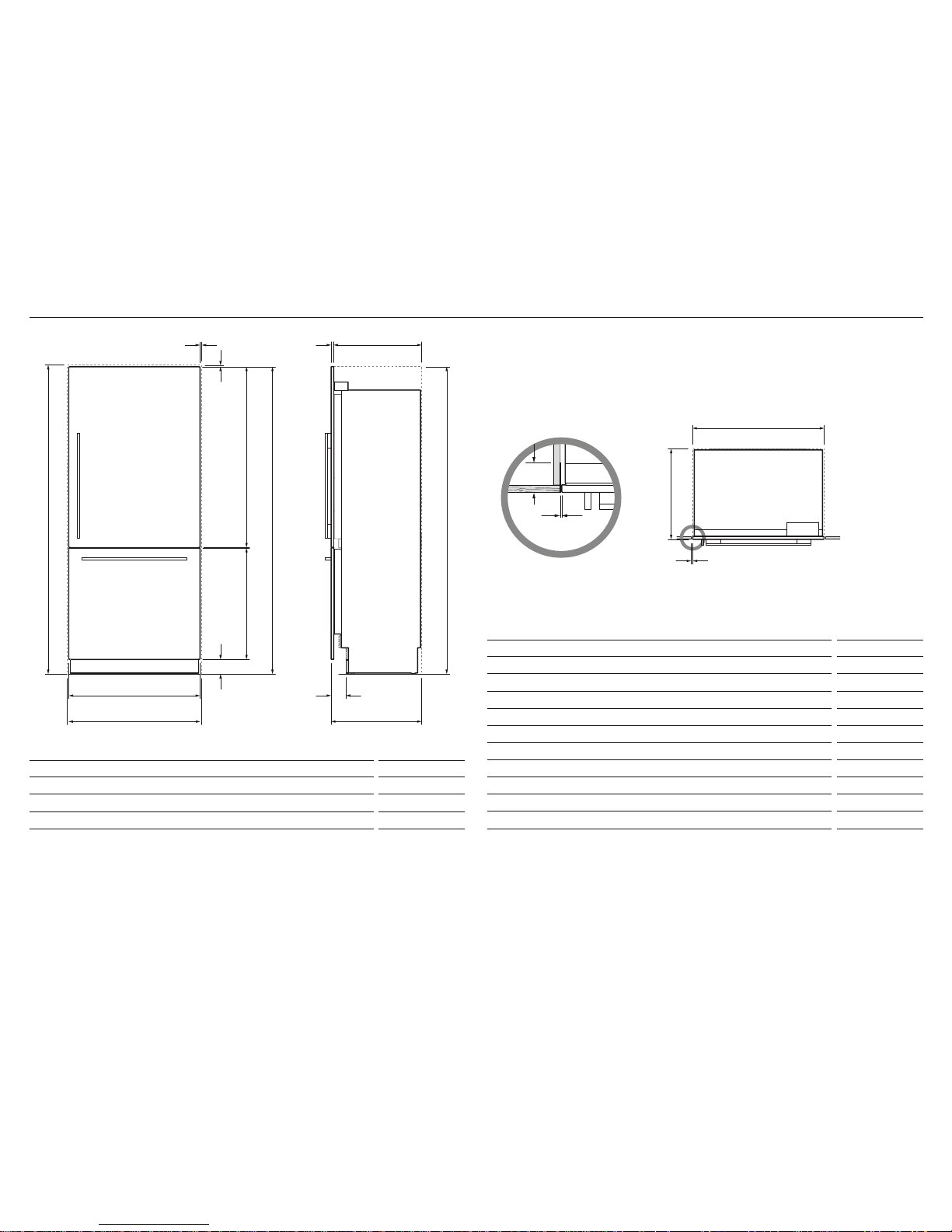
4 PRODUCT AND CAVITY DIMENSIONS – WITH RD9121WR/RD9121WRU DOOR PANEL SET
RS9120WRJ models shown with RD9121WR door panels.
CAVITY DIMENSIONS mm
A
Overall height of cavity 2134
B
Overall width of cavity 914
C
Overall depth of cavity* 635
Total front panel width with required gaps at sides = 914mm ( E product width + 2 x F cabinetry gaps).
Height of front panels with required gap above = 2134mm (
D product height + F cabinetry gap).
* Assumes a door panel thickness of 19mm.
PRODUCT DIMENSIONS
mm
D
Overall height of refrigerator* 2130
E
Overall width of refrigerator 906
F
Minimum cabinetry gap clearance from edge of refrigerator 4
G
Overall depth of refrigerator (excl. front door panels) 606
H
Depth of stainless steel toe kick (measured from front of door panels) 71–101
I
Height of stainless steel toe kick** 102
J
Height of bottom drawer panel 772
K
Height of top door panel 1252
L
Depth of refrigerator front panels (excludes handles)*** 19
M
Cabinetry finished return (side and top of cavity) min. 127
* Includes mounted feet.
** Alternatively customers can supply their own toe kick, height 102 – 152mm.
*** Optional Fisher & Paykel EZKleen steel front panels. Model no. RD9121W(L/R) (Automatic ice model) and
model no. RD9121WRU (Ice & Water model).
Flush with front
of cabinetry
PLAN VIEW
PROFILE VIEWFRONT VIEW
E
B
H
C
A
DA
J
I
L G
PLAN VIEW
C
B
F
F
F
K
PRODUCT & CAVITY DIMENSIONS
H
C
A
L G
PLAN VIEW
C
B
F
PRODUCT & CAVITY DIMENSIONS
PLAN VIEW
C
B
F
PRODUCT & CAVITY DIMENSIONS
M
M
F
F
8
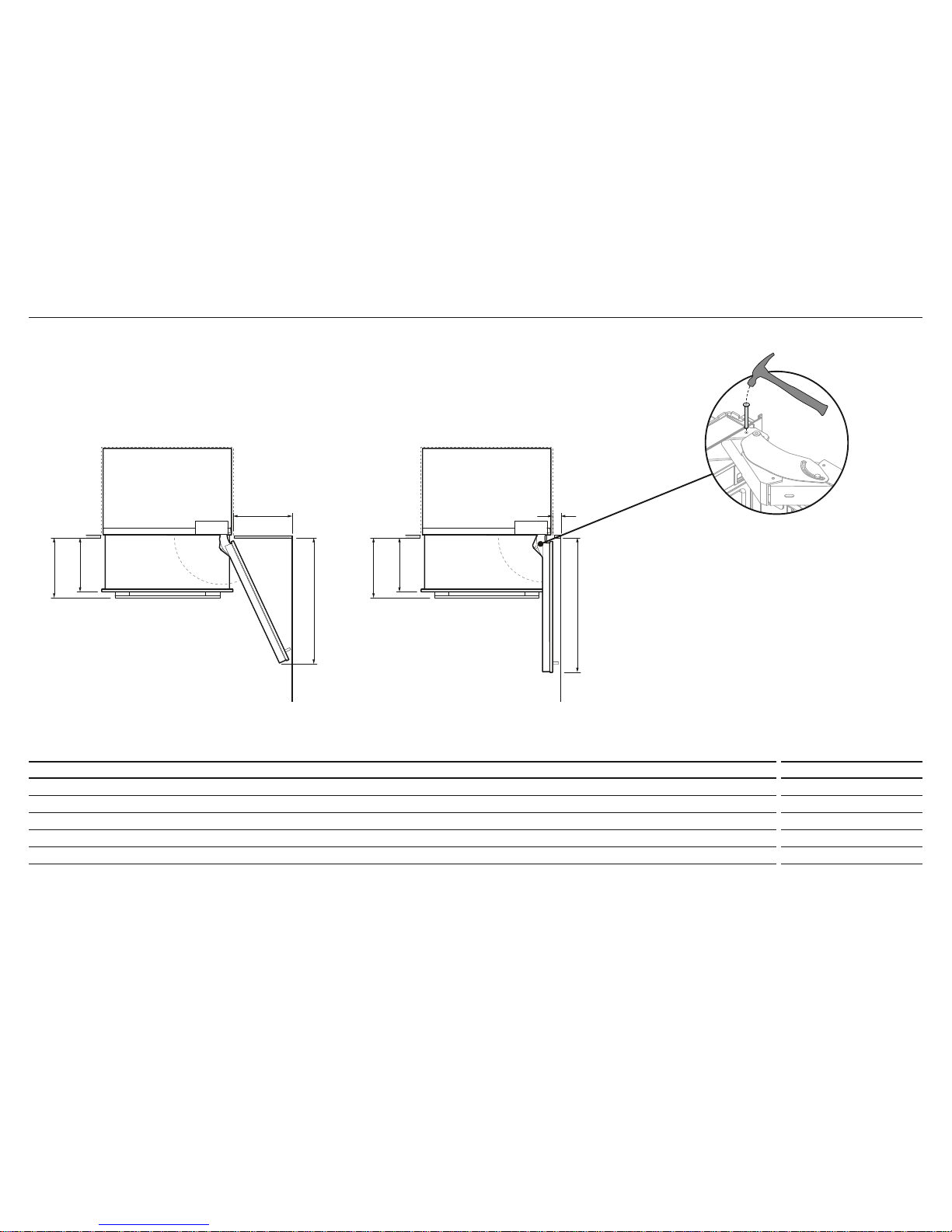
4 PRODUCT AND CAVITY DIMENSIONS – WITH RD9121W DOOR PANEL SET
RS9120WRU
RS9120W(R/L)J
DOOR OPENING AND CLEARANCE DIMENSIONS mm
A
Depth of door (widest opening) measured from front of door 940
B
Depth of drawer (open) measured from front of drawer, including handle 400
C
Depth of drawer (open) measured from front of drawer, excluding handle 360
D
Minimum door clearance to adjacent wall* (115° – full internal access) 410
E
Minimum door clearance to adjacent wall* (90° – reduced internal access) 110
* Measured from front cabinetry edge.
DOOR OPENING & CLEARANCE DIMENSIONS
d
A
b
c
b
c
a
e
Wall
115° DOOR OPENING
(FULL ROTATION)
b
c
a
e
Wall
90° DOOR OPENING
Z
For 90° door swing a hinge limiting pin is supplied with
your appliance. This pin fits in the boreholes of the top
hinge (refer to Z).
WARNING!
Before opening the doors, ensure that the refrigerator is
on its base packer and the polystyrene stability blocks
are still in place.
Drawer must be closed when fitting the hinge limiting pin.
Follow these instructions to avoid risks that can cause
serious injury or death.
1
Open door to 90°.
2
Align the hinge limiting pin vertically with the bore hole.
3
Use a hammer to drive the pin through the bore hole.
9
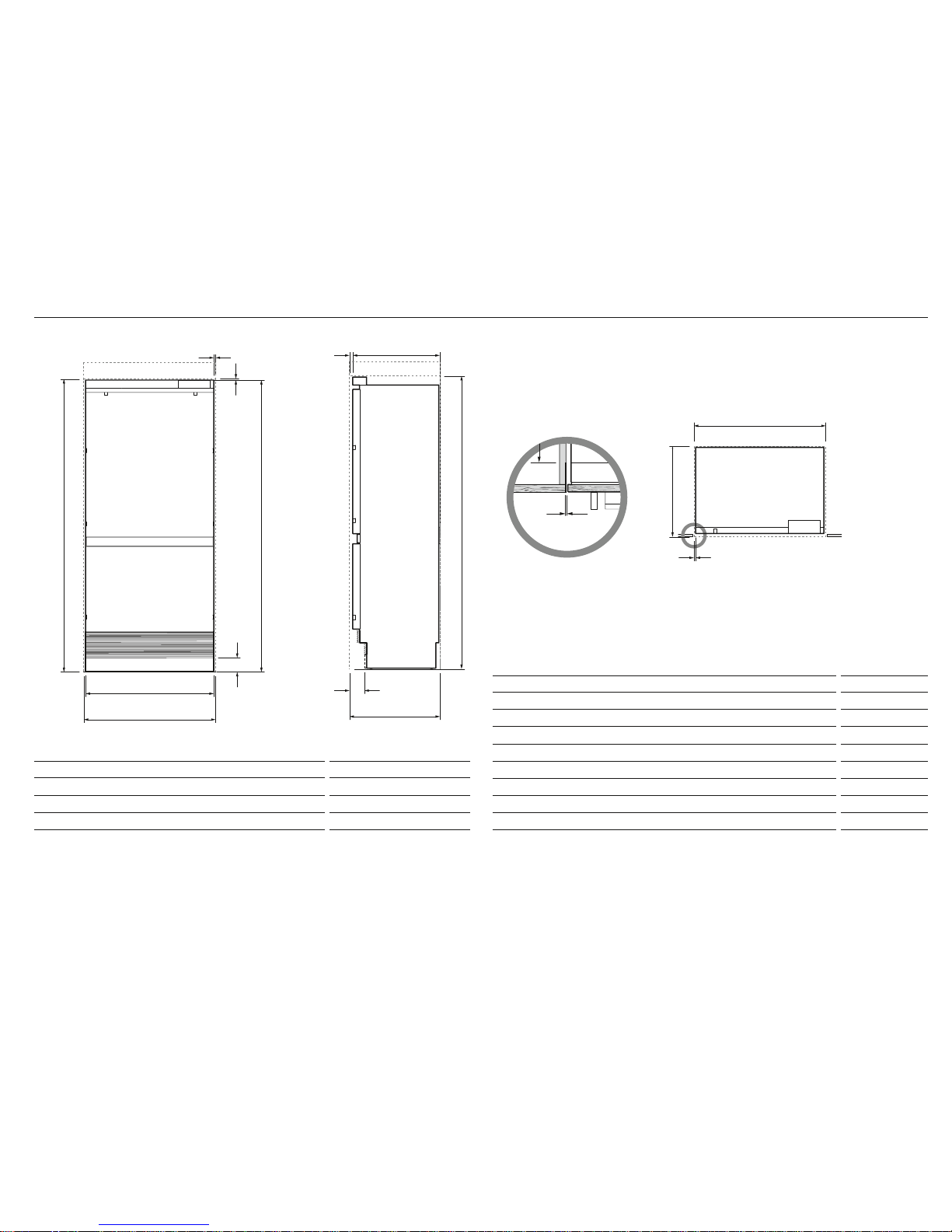
4 PRODUCT AND CAVITY DIMENSIONS
PRODUCT DIMENSIONS
mm
D
Overall height of refrigerator* (does not include front panels) 2028
E
Overall width of refrigerator (does not include front panels) 890
F
Minimum cabinetry gap clearance from edge of custom panels** 4
G
Overall depth of refrigerator (excl. front door panels) 606
H
Depth of toe kick (measured from front of door panels***) 71–101
I
Height of custom toe kick**** 102–152
J
Depth of refrigerator front panels (excludes handles)*** 19
K
Cabinetry finished return (side and top of cavity) min. 127
* Includes mounted feet.
** Refer to ‘Custom door panel dimensions’ section.
*** Door panels to be manufactured and fitted by cabinetmaker, maximum thickness 19mm.
**** Stainless steel toe kick provided with appliance. Alternatively, customers can supply their own toe kick, height
102–152mm.
CAVITY DIMENSIONS mm
A
Overall height of cavity* 2032/2134
B
Overall width of cavity 914
C
Overall depth of cavity** 635
Total front panel width with required gaps at sides = 914mm. Refer to ‘Custom door panel dimensions’ section – panel
width + 2 x
F cabinetry gaps).
* Supplied top trim enables cavity height to be either 2032mm or 2134mm.
** Assumes a door panel thickness of 19mm.
RS9120WJ model shown only.
When designing custom door panels, these are only available for Automatic ice models.
PROFILE VIEWFRONT VIEW
Flush with front
of cabinetry
E
B
H
C
A
A
I
J G
C
B
F
F
D
F
H
C
A
J G
C
B
F
PLAN VIEW
Note: shown with custom
panel and handles attached
to fridge
J G
C
B
F
F
K
F
K
F
10
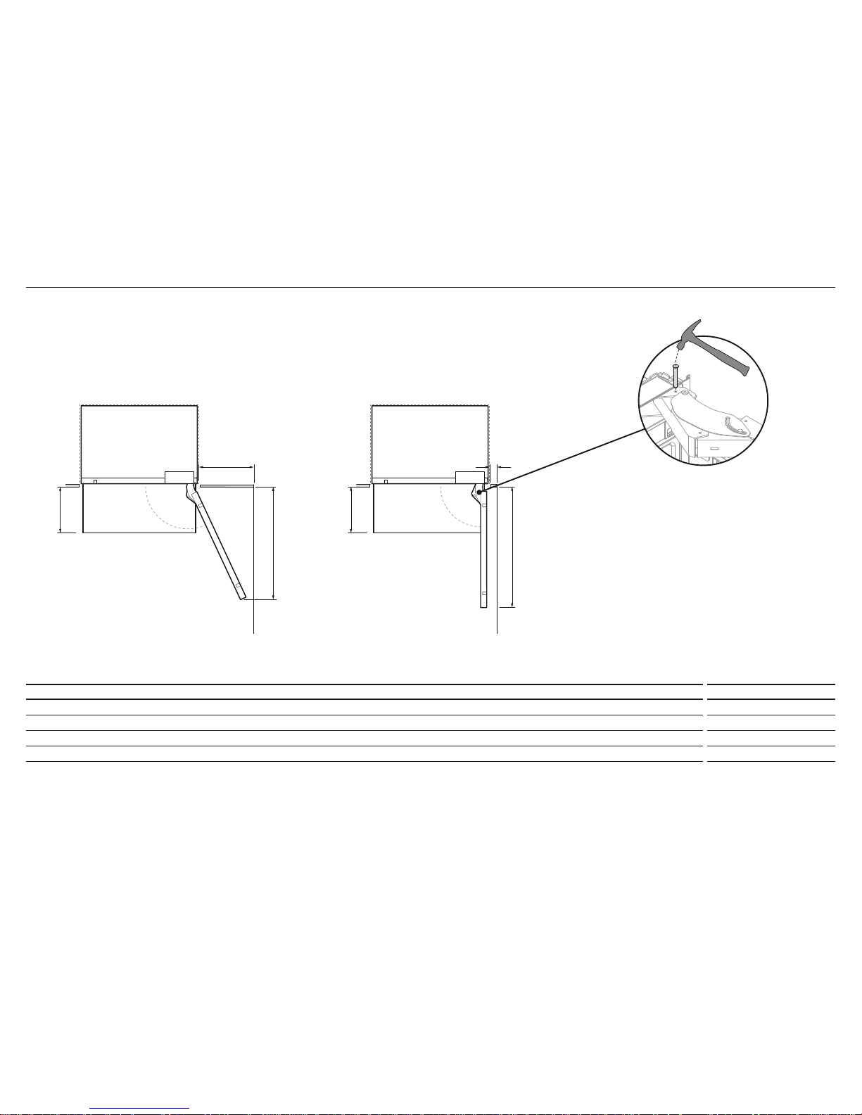
4 PRODUCT AND CAVITY DIMENSIONS
DOOR OPENING AND CLEARANCE DIMENSIONS mm
A
Depth of door (widest opening) measured from front of door 940
B
Depth of drawer (open) measured from front of cabinetry* 338
C
Minimum door clearance** to adjacent wall* (115° – full internal access) 410
D
Minimum door clearance** to adjacent wall* (90° – reduced internal access) 110
* Does not include the custom door panels or handles to be manufactured and fitted by cabinetmaker.
** Measured from front cabinetry edge.
c
A
b
b
a
d
b
a
d
Wall Wall
115° DOOR OPENING
(FULL ROTATION)
90° DOOR OPENING
For 90° door swing a hinge limiting pin is supplied with
your appliance. This pin fits in the boreholes of the top
hinge (refer to Z).
WARNING!
Before opening the doors, ensure that the refrigerator is
on its base packer and the polystyrene stability blocks
are still in place.
Drawer must be closed when fitting the hinge limiting pin.
Follow these instructions to avoid risks that can cause
serious injury or death.
1
Open door to 90°.
2
Align the hinge limiting pin vertically with the bore hole.
3
Use a hammer to drive the pin through the bore hole.
Z
 Loading...