

Page 1
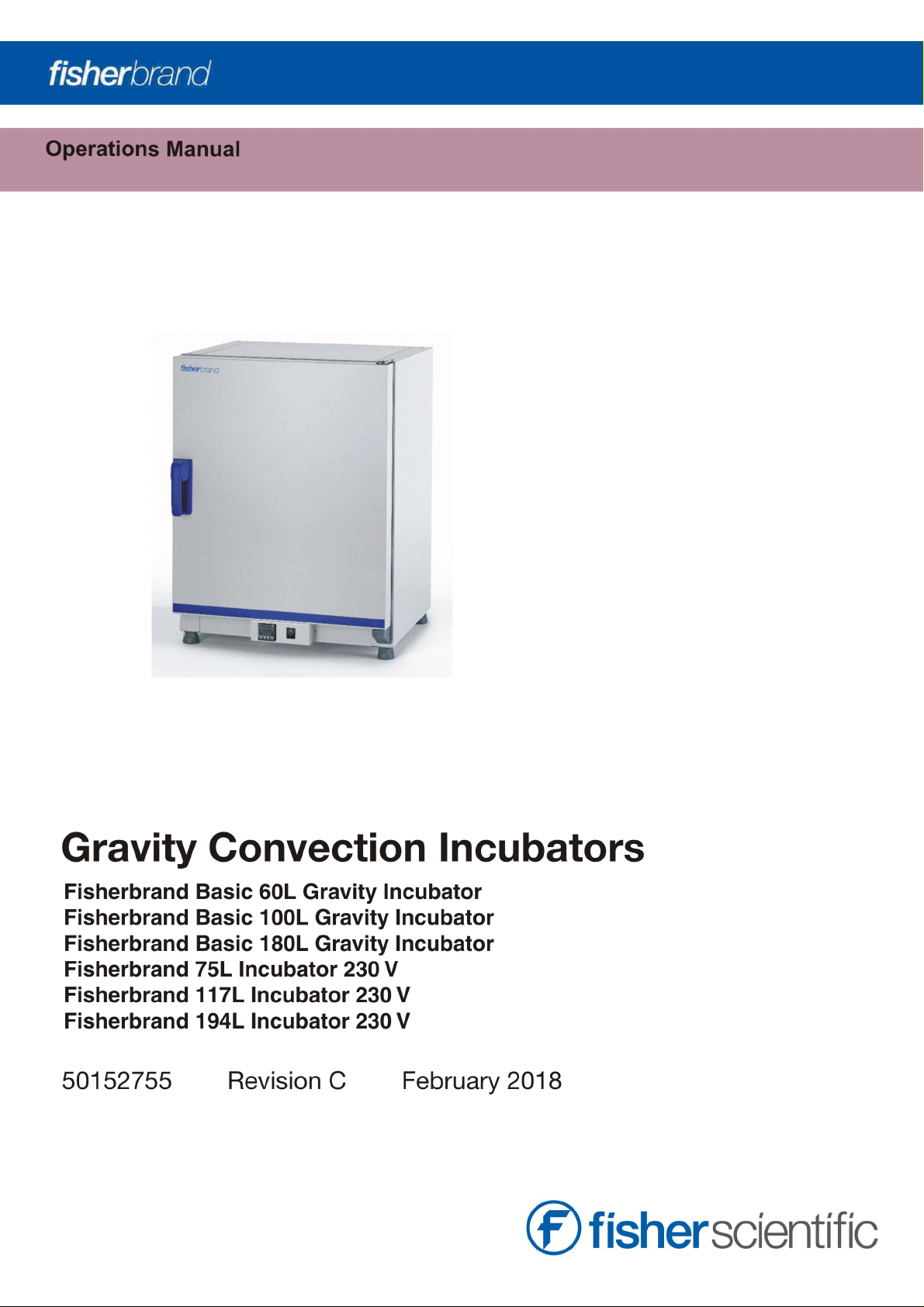
Page 2

© 2018 Thermo Fisher Scientific. All rights reserved.
This Instruction Manual is copyright protected. Rights resulting thereof, particularly reprint, photomechanical or digital postprocessing or reproduction, even in part, are only allowed with the written consent of Thermo Fisher Scientific.
This regulation does not apply to reproductions for in-plant use.
The contents of this document are subject to change without notice. Concerning translations into foreign languages, the English
version of these operating instructions is binding.
Trademarks
All trademarks mentioned in the operating instructions are the exclusive property of the respective manufacturers.
Thermo Fisher Scientific
300 Industry Drive
Pittsburgh, Pennsylvania 15275
United States
Thermo Fisher Scientific provides this document to its customers with a product purchase to use in the product operation. This
document is copyright protected This document is copyright protected and any reproduction of the whole or any part of this
document is strictly prohibited, except with the written authorization of Thermo Fisher Scientific.
The content of this document are subject to change without notice.
All technical information in this document is for reference purposes only. System configurations and specifications in this document
supersede all previous information received by the purchaser.
This document is not part of any sales contract between Thermo Fisher Scientific and a purchaser. This document shall in no way
govern or modify any Terms and Conditions of Sale, which Terms and Conditions of Sale shall govern all conflicting information
between the two documents.
Page 3

Table of Contents
Chapter 1 Table of Contents .....................................................................................................................................................1
Chapter 2 Safety Notes.............................................................................................................................................................1
Basic Operating Precautions........................................................................................................................................1
Operational Safety Rules .............................................................................................................................................2
Warranty....................................................................................................................................................................2
Explanation of Safety Information and Symbols .............................................................................................................3
.............................................................................................................................................................................3
Additional Symbols for Safety Information ................................................................................................................3
Symbols on the Incubator........................................................................................................................................4
Intended Purpose of the Incubator ...............................................................................................................................5
Correct Use............................................................................................................................................................5
Incorrect Use..........................................................................................................................................................5
Standards and Directives ............................................................................................................................................5
Chapter 3 Delivery of the Incubator..........................................................................................................................................7
Packaging..................................................................................................................................................................7
Acceptance Inspection ................................................................................................................................................7
Scope of Supply .........................................................................................................................................................8
Incubators..............................................................................................................................................................8
Chapter 4 Installation ...............................................................................................................................................................9
Ambient Conditions ....................................................................................................................................................9
Location Requirements ...........................................................................................................................................9
Intermediate Storage ................................................................................................................................................10
Room Ventilation ......................................................................................................................................................10
Incubator Dimensions and Clearances ...................................................................................................................11
Transport .............................................................................................................................................................12
Installing the Anti-tilt Anchor .....................................................................................................................................13
Chapter 5 Product Description................................................................................................................................................15
Basic Gravity Incubator Overview ...............................................................................................................................15
Work Space Atmosphere...........................................................................................................................................16
Sensing and Control System......................................................................................................................................17
AC Power Socket..................................................................................................................................................17
Fuses ..................................................................................................................................................................17
Work Space Components ..........................................................................................................................................18
Inner Chamber .....................................................................................................................................................18
Access Port..........................................................................................................................................................18
Shelf System........................................................................................................................................................19
Chapter 6 Start-up..................................................................................................................................................................21
Installing the Shelf System ........................................................................................................................................21
Initial Installation.......................................................................................................................................................21
Preparing the Work Space.........................................................................................................................................22
Installation of the Support Rails .............................................................................................................................22
Installing the Shelf Support Brackets......................................................................................................................23
Installing the Perforated Shelves............................................................................................................................23
Levelling the Incubator ..........................................................................................................................................24
Fisherbrand 50152755 | 1
Page 4

Connecting Power ....................................................................................................................................................24
Connecting to the Power Supply Source.................................................................................................................24
Electrical Requirements to be Met when Operating the Incubators in the European Union:.............................................25
Chapter 7 Operation................................................................................................................................................................27
Preparing the Incubator.............................................................................................................................................27
Device Check .......................................................................................................................................................27
Starting Operation ................................................................................................................................................27
Chapter 8 Handling and Control..............................................................................................................................................29
Overview..................................................................................................................................................................29
Operator mode .....................................................................................................................................................30
Calibration of the reference sensor ........................................................................................................................31
Chapter 9 Shut-down .............................................................................................................................................................33
Shutting the Incubator Down .....................................................................................................................................33
Chapter 10 Cleaning and Disinfection ......................................................................................................................................35
Cleaning ..............................................................................................................................................................35
Cleaning Exterior Surfaces ....................................................................................................................................35
Wipe / Spray Disinfection ..........................................................................................................................................35
Preparing the Manual Wipe/Spray Disinfection .......................................................................................................37
Predisinfection .....................................................................................................................................................37
Cleaning ..............................................................................................................................................................37
Final Disinfection ..................................................................................................................................................38
Chapter 11 Maintenance ..........................................................................................................................................................39
Inspections and Checks ............................................................................................................................................39
Regular Checks ....................................................................................................................................................39
Semi-annual Inspection ........................................................................................................................................39
Service Intervals .......................................................................................................................................................40
3-monthly service.................................................................................................................................................40
Annual Service .....................................................................................................................................................40
Replacing the Door Seal ............................................................................................................................................41
Replacing the Power Cord.........................................................................................................................................41
Returns for Repair ....................................................................................................................................................41
Chapter 12 Disposal .................................................................................................................................................................43
Overview of Materials Used .......................................................................................................................................43
Chapter 13 Error Codes ............................................................................................................................................................45
Chapter 14 Technical Data .......................................................................................................................................................47
Chapter 15 Accessories ............................................................................................................................................................51
Chapter 16 Device Log..............................................................................................................................................................53
2
|
50152755 Fisherbrand
Page 5

List of Figures
Figure 3-1 Incubator dimensions and required clearances................................................................................................ 11
Figure 3-2 Lift Points ..................................................................................................................................................... 12
Figure 4-1. Fisherbrand Basic 60L/100L/180L Gravity Incubator Front View...................................................................... 15
Figure 4-2. Fisherbrand Basic 60L/100L/180L Gravity Incubator Rear View ...................................................................... 16
Figure 4-3. Sensor System............................................................................................................................................. 17
Figure 4-4. Basic Gravity Incubator Shelf System ............................................................................................................. 19
Figure 5-1. Sliding the Retaining Spring into the Support Rail ........................................................................................... 21
Figure 5-2. Support Rail Installation ................................................................................................................................ 22
Figure 5-3. Shelf Support Installation .............................................................................................................................. 23
Figure 5-4. Installing the Perforated Shelves.................................................................................................................... 23
Figure 7-1. Control Panel for Fisherbrand Basic Gravity Incubator ..................................................................................... 29
Figure 10-1. Door seal ................................................................................................................................................... 41
Fisherbrand part-number 1
Page 6

2
part-number Fisherbrand
Page 7

Safety Notes
Basic Operating Precautions
These operating instructions describe Fisherbrand incubators.
Fisherbrand incubators have been manufactured to the latest state of the art and have been
tested thoroughly for flawless functioning prior to shipping. However, the incubator may present
potential hazards, particularly if it is operated by inadequately trained personnel or if it is not used
in accordance with the intended purpose. Therefore, the following must be observed for the sake
of accident prevention:
Never step into the unit.
Fisherbrand incubators must be operated by adequately trained and authorized professional
personnel.
Fisherbrand incubators must not be operated unless these operating instructions have been
fully read and understood.
The present operating instructions, applicable safety data sheets, plant hygiene guidelines
and the corresponding technical rules issued by the operator shall be used to create written
procedures targeted at personnel working with the subject matter device, detailing:
the decontamination measures to be employed for the incubator and the accessories
used with it,
the safety precautions to be taken when processing specific agents,
the measures to be taken in case of accidents.
Repair work on the incubator must be carried out only by trained and authorized expert personnel.
The contents of these operating instructions are subject to change at any time without further
notice.
Keep these operating instructions close to the incubator so that safety instructions and
important information are always accessible.
Keep the door open-times during operation always as short as possible. The longer the door
is open, the higher can be a possible overshooting of the temperature. After a door opening
allow the incubator to the set-point temperature, before opening again.
Should you encounter problems that are not detailed adequately in these operating instructions,
please contact Fisher Scientific International, LLC immediately for your own safety.
Fisherbrand 50152755 | 1
Page 8

Chapter 1
| Safety Notes
Operational Safety Rules
The following rules must be heeded when working with Fisherbrand incubators:
Observe the sample weight limits specified for your Fisherbrand incubator as a whole and its
shelving in particular; see “Technical Data” on page 47.
Do not load the bottom of the interior workspace to avoid the risk of overheating any samples
placed there and to prevent the temperature sensor from being damaged.
Arrange the samples evenly throughout the work space, making sure not to place them too
closely to the interior walls to ensure a uniform temperature distribution.
Do not load your Fisherbrand incubator with substances that exceed the capabilities of the
available lab apparatus and Personal Protection Equipment to provide sufficient degrees of
protection to users and third parties.
Check the door seal every six months for proper sealing performance and possible damage.
Do not process any samples containing hazardous chemical substances that may be
released into the ambient air through defective seals or may cause corrosion or other defects
on parts of the Fisherbrand incubator.
Warranty
Fisher Scientific International, LLC warrants the operational safety and functions of the
Fisherbrand incubators only under the condition that:
the incubator is operated and serviced exclusively in accordance with its intended purpose
and as described in these operating instructions,
the incubator is not modified,
only original spare parts and accessories that have been approved by Fisher Scientific care
used (third-party spares without Fisher Scientific International, LLC approval void the limited
warranty),
inspections and maintenance are performed at the specified intervals,
an operation verification test is performed after each repair activity.
The warranty is valid from the date of delivery of the incubator to the customer.
2
|
50152755 Fisherbrand
Page 9
Safety Notes |
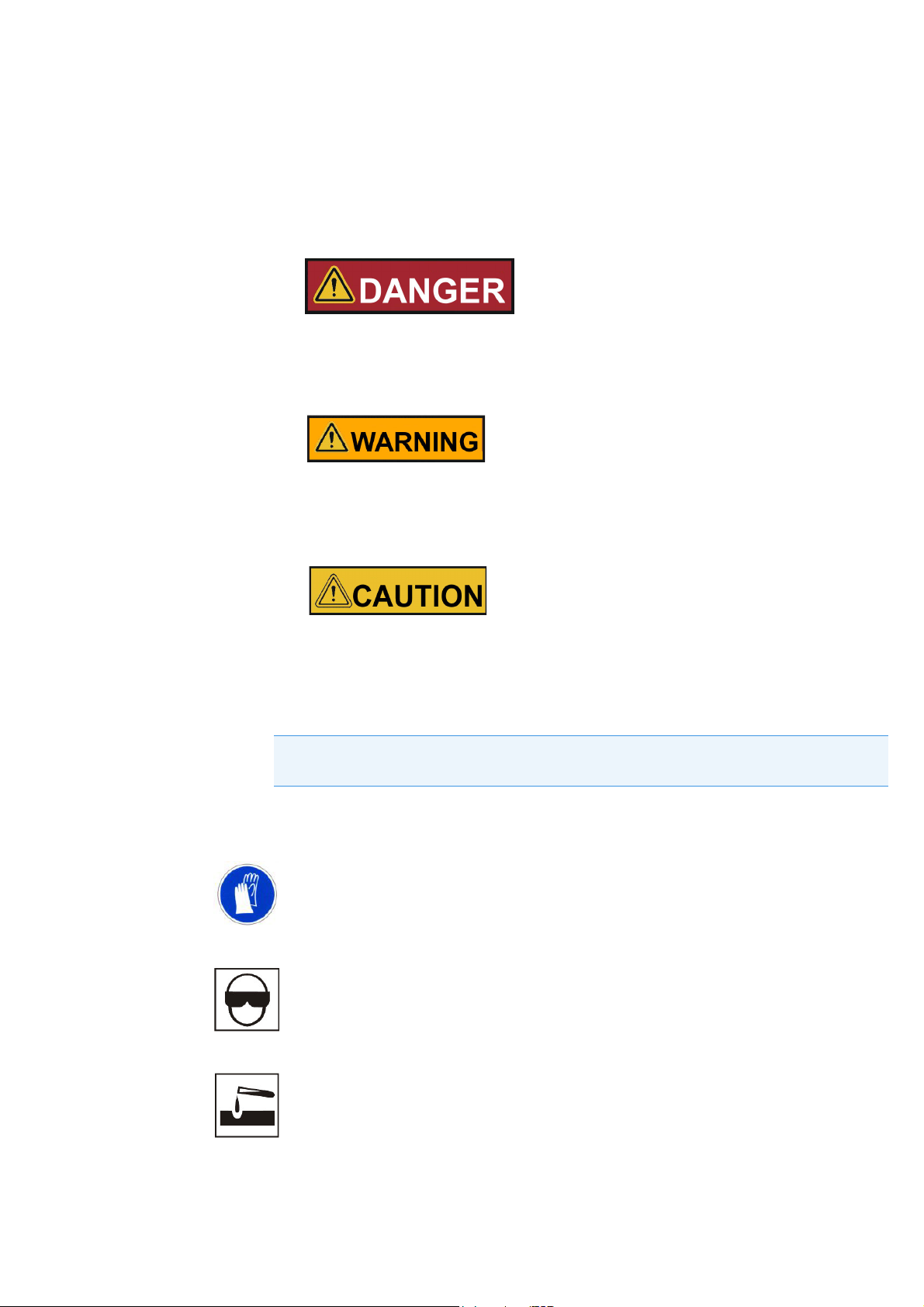
Indicates a hazardous situation which, if not avoided, will result in death or serious
injuries.
Indicates a hazardous situation which, if not avoided, could result in death or serious
injuries.
Indicates a situation which, if not avoided, could result in damage to
equipment or property.
Chapter 1
Explanation of Safety Information and Symbols
Safety Notes and Symbols Used Throughout These
Operating Instructions
NOTE
Is used for useful hints and information regarding the application.
Additional Symbols for Safety Information
Wear safety gloves!
Wear safety goggles!
Harmful liquids!
Fisherbrand 50152755 | 3
Page 10
Chapter 1
| Safety Notes
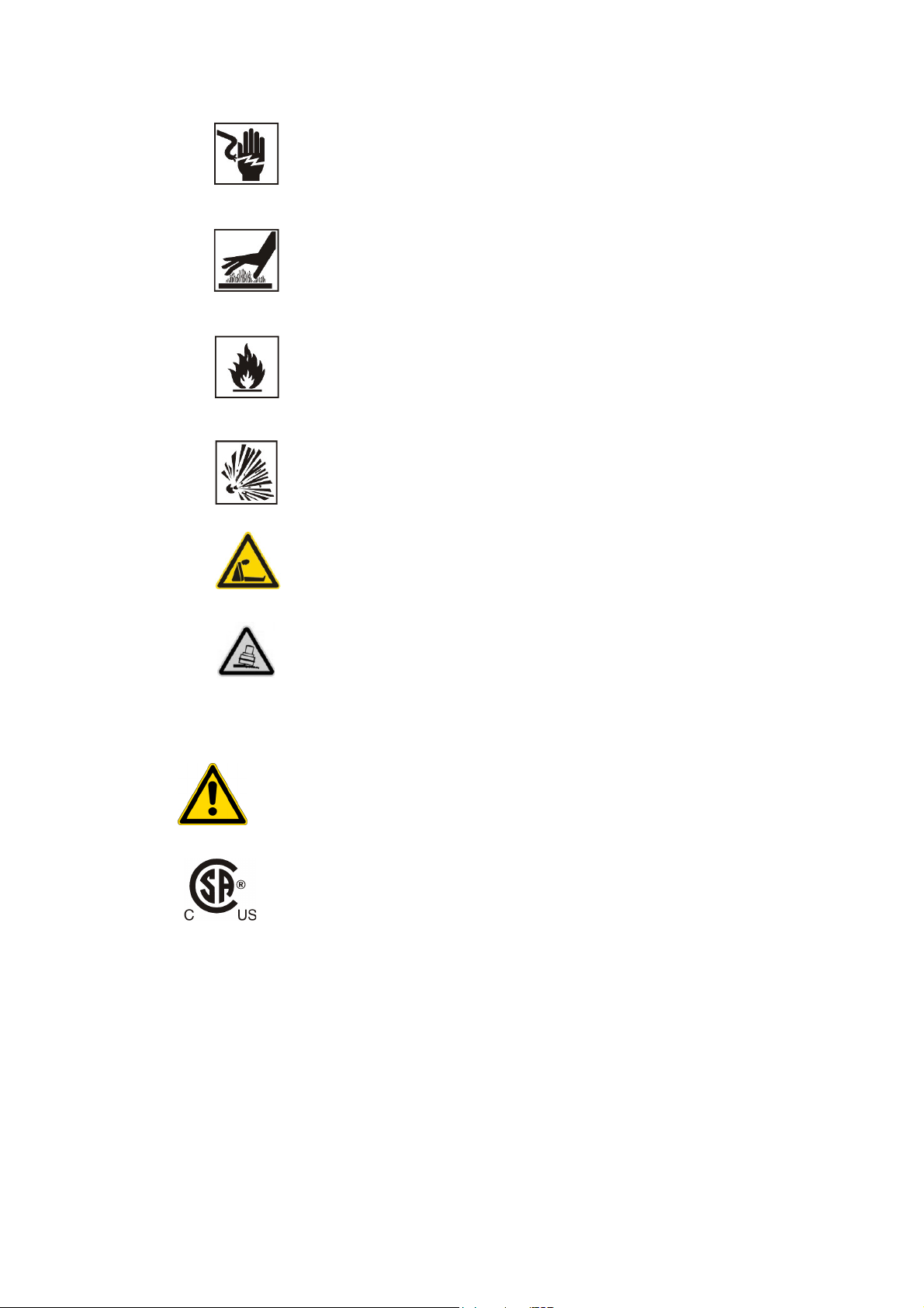
Electric shock!
Hot surfaces!
Fire hazard!
Explosion hazard!
Suffocation hazard!
Danger of tipping
!
Symbols on the Incubator
Observe operating instructions
Mark of conformity USA/Canada
4
|
50152755 Fisherbrand
Page 11

Safety Notes |
Chapter 1
Intended Purpose of the Incubator
Correct Use
Fisherbrand incubators are laboratory devices for preparing and cultivating cell and tissue
cultures. The devices employ precision temperature control for simulating the specific
physiological ambient conditions for these cultures.
Fisherbrand incubators are for professional use only.
Incorrect Use
To avoid the risk of explosion do not load the incubator with tissue, material, or liquids that:
are easily flammable or explosive,
release vapor or dust that forms combustible or explosive mixtures when exposed to air,
release poisons,
do not pour any liquids on the bottom of the interior surface or into a collecting basin inside
the unit.
release dust
exhibit exothermic reactions
are pyrotechnical substances
refrain also from pouring any liquids onto the internal base plate or inserting bowls filled with
liquids into the sample compartment.
Standards and Directives
The incubator complies with the following standards and guidelines:
IEC/CAN/CSA-C22.2/UL 61010 - 1
IEC/CAN/CSA-C22.2 61010 - 2 - 010
China EEP Hazardous Substances Information
http://www.thermofisher.com/us/en/home/technical-resources/rohs-certificates.html.
Additionally, the incubator is in compliance with many other international standards, regulations
and directives not listed here. Should you have any questions regarding compliance with national
standards, regulations and directives applicable for your country, please contact your Fisherbrand
sales organization.
Fisherbrand 50152755 | 5
Page 12

Chapter 1
| Safety Notes
6
|
50152755 Fisherbrand
Page 13
Delivery of the Incubator
Packaging
Fisherbrand incubators are delivered in a rugged packaging box. All packaging materials can be
separated and are reusable:
Packaging materials
Packaging carton: Recycled paper
Foam elements: Styrofoam (CFC-free)
Pallet: Chemically untreated wood
Packaging film: Polyethylene
Packaging ribbons: Polypropylene
Acceptance Inspection
After the incubator has been delivered, check the delivery immediately for:
completeness,
possible damage.
If components are missing or damage is found on the incubator or the packaging, in particular
damage caused by humidity and/or water, please notify the carrier as well as Fisherbrand
Technical Support immediately.
Risk of injury
Should sharp edges have formed in damaged areas or elsewhere on the device, take
all necessary precautions to protect personnel handling the incubator. For example,
have them wear protective gloves and other personal protection equipment.
Fisherbrand 50152755 | 7
Page 14

Chapter 2
| Delivery of the Incubator
Scope of Supply
Incubators
Quantity of components supplied (pieces)
Gravity Convection
Incubators
Perforated shelves 2
Support rail for shelf table-top incubators 4
Shelf support 4
Power cord 1
Clip springs for table-top incubators 4
Plug 1
Anti-tilt anchor 1
Operating manual 1
Summarized Safety Instructions 1
8
|
50152755 Fisherbrand
Page 15

Installation
Ambient Conditions
Location Requirements
The incubator must only be operated in a location that meets all of the ambient condition
requirements listed below:
Installation location indoors in dry areas free from drafts.
The dust burden may not exceed the contamination category 2 based on IEC61010-1. Using
the incubator in an atmosphere with electrically conductive dust is prohibited.
The minimal distance to adjacent surfaces must be observed on all sides (see Section
“Incubator Dimensions and Clearances” on page 11)
The operating room must be equipped with appropriate ventilation.
Solid, level, fire-proof surface; no flammable materials opposite to the rear panel of the
incubator.
Vibration-proof substructure (floor stand, lab table) capable of bearing the dead weight of the
incubator and its accessories (particularly if two devices are stacked).
The electrical circuitry of the incubator has been designed for an operating height of up to
2000 m above sea level.
Relative humidity up to 80% (maximum; preferably 60-70%), non condensing.
Should condensation exist, wait until the moisture has evaporated completely before
connecting the incubator to a power source and powering up.
The ambient temperature must be within a range of +18 °C to +32 °C (64.4 °F to 89.6 °F).
Avoid direct exposure to sunlight.
Devices that produce excessive amounts of heat must not be placed near the incubator.
Place the incubator on a floor stand (option; to be ordered separately), never on the lab floor.
This prevents the penetration of dust or dirt into the device.
Power line voltage variations must not exceed ±10 % of the nominal voltage.
Transient surges must lie within the range of levels that normally occur in the power supply
system. The impulse withstand voltage based on surge category II of IEC 60364-4-443 shall
be applied at the nominal voltage level.
Fisherbrand 50152755 | 9
Page 16
Chapter 3
| Installation
Consider installing one dedicated upstream circuit breaker per incubator to avoid multiple
device failures in case of an electrical fault.
Contamination hazard
Do not place the incubator directly on the lab floor, but mount it on the floor stand or on
a lab work surface (option; to be ordered separately). Contaminants, such as bacteria,
viruses, fungi, prions, and other biological substances may use the open door to
migrate easily from the floor into the incubator’s work space.
Intermediate Storage
When the incubator is placed in intermediate storage, make sure that the ambient temperature is
between 20 °C to 60 °C (68 °F to 140 °F) and the maximum relative humidity does not exceed
90%, non-condensing.
Room Ventilation
Heat dissipating from the incubator during continuous operation may cause a change in the room
climate.
Therefore, the incubator must only be installed in rooms with sufficient ventilation.
Do not install the incubator in room recesses without ventilation.
When several devices are to be placed in the same room, additional ventilation may have to
be provided as necessary.
To avoid any impact of the heat dissipated by the incubator on the ambient climate the room
must be vented by means of a laboratory-grade ventilation system that complies with
applicable local and national health and safety regulations and has sufficient capacity.
If excessive temperatures tend to occur in the operating room, be sure to provide a thermal
protection means that cuts out the power supply to mitigate the impact of over-temperature
scenarios.
10
|
50152755 Fisherbrand
Page 17
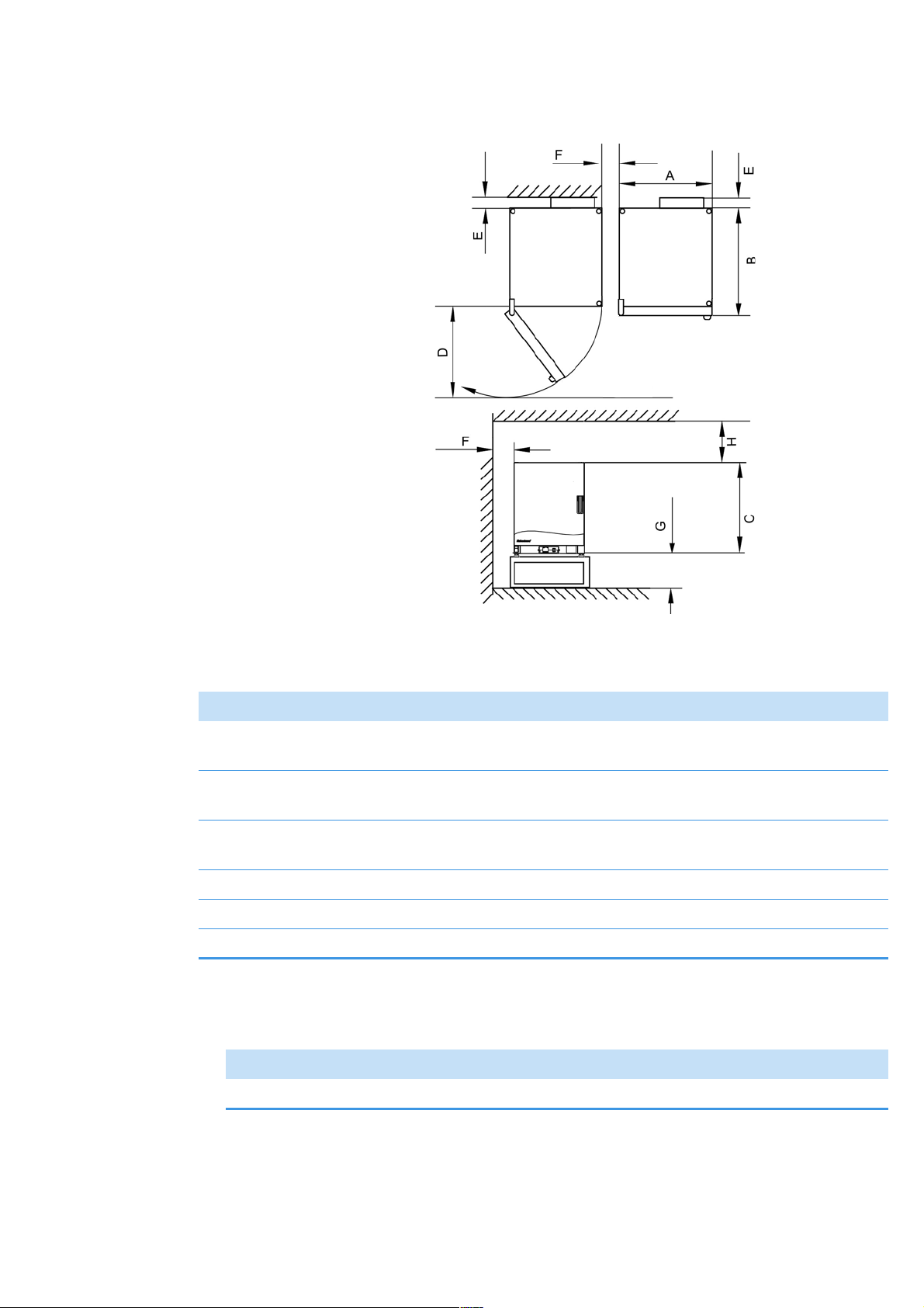
Incubator Dimensions and Clearances
Installation |
Chapter 3
Figure 3-1 Incubator dimensions and required clearances
Table 3-1 Incubator Dimensions
Type A (mm/inch*) B (mm/inch) C (mm/inch D (mm/inch)
Fisherbrand Basic 60L Gravity
530 / 20.8 565 / 25.2 720 / 28.3 540 / 21.3
Incubator 120 V
Fisherbrand Basic100L Gravity
640 / 25.2 565 / 25.2 820 / 32.3 650 / 25.6
Incubator 120 V
Fisherbrand Basic180L Gravity
640 / 25.2 738/ 29.1 920 / 36.2 650 / 25.6
Incubator 120 V
Fisherbrand 75L Incubator 230 V 530 / 20.8 565 / 25.2 720 / 28.3 540 / 21.3
Fisherbrand 117L Incubator 230 V 640 / 25.2 565 / 25.2 820 / 32.3 650 / 25.6
Fisherbrand 194L Incubator 230 V 640 / 25.2 738/ 29.1 920 / 36.2 650 / 25.6
*
Dimensions in inches are rounded equivalents specified for information only. Depth of handle /display (66 mm/2.6 in) not included in overall depth specified;
height of adjustable feet (36 mm/1.4 in) not included in overall height specified.
Table 3-2 Required Clearances
E (mm/inch) F (mm/inch) G (mm/inch) H (mm/inch)
80 / 3.2 50 / 2 300 / 12 300 / 12
Fisherbrand 50152755 | 11
Page 18
Chapter 3
| Installation
Transport
Table-top incubators
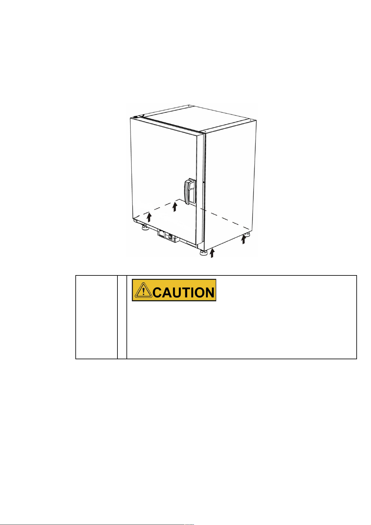
For transport, do not lift the incubator using the doors or components attached to the incubator as
lift points.
Figure 3-2 Lift Points
Heavy loads! Lift with care!
To avoid injury through physical strain, such as strain traumata and slipped discs, do
not attempt to lift the incubator alone!
To avoid injury through dropped loads, be sure to wear Personal Protection Equipment,
such as safety shoes, when lifting the incubator.
To avoid crushing your fingers or hands (particularly in a closing door) or damaging the
incubator, do not use any other lift points than those indicated in the illustration above.
12
|
50152755 Fisherbrand
Page 19
Installation |
Chapter 3
Installing the Anti-tilt Anchor
Table-top incubators
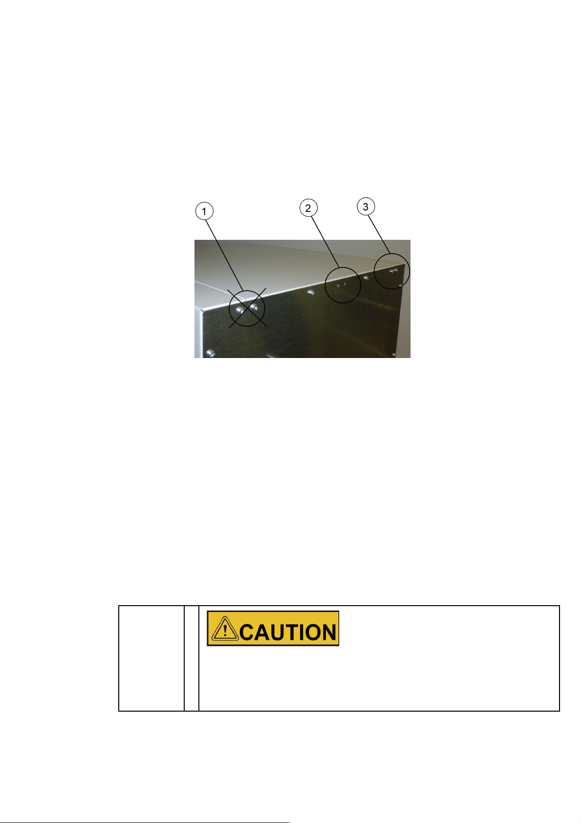
The anti-tilt anchor secures the device to a solid part of a building. The anti-tilt anchor is to be
mounted on the side opposite of the door hinges.
Bend the fixing tabs of the anti-tilt anchor up on one side and down on the other by an angle of
approx. 90°.
1. Do not use this position if the door is hinged on this side. Right-hand hinges represent the
standard configuration.
2. Preferred position.
3. Alternative position. Do not use if the door is hinged on this side.
4. Remove the bracket screws. Use the preferred position, if possible.
5. Fix the anti-tilt anchor with the bracket side down to the unit.
6. Position the unit with the anti-tilt anchor to in an angle of approx. 90° +/- 20%.
7. Take care that the stacking feet of the unit are still in correct place on the lower unit or on the
stacking adapter.
8. Fix the anti-tilt anchor to a solid part of the building.
Additionally, the following caution notes must be heeded at all times:
Unsafe part of the building!
Install the anti-tilt anchor to a solid part of the building, which is able for shoring loads.
The installation has to be carried out by qualified personnel only.
The connection to the building must be carried out with appropriate screws and
dowels according to the consistence of the building part.
Fisherbrand 50152755 | 13
Page 20
Chapter 3
| Installation
Risk of overheating with stacked devices
To avoid the risk of electrical components and the outer enclosure overheating or
temperature control failing due to insufficient ventilation, do not exceed the specified
stacking height!
Risk of tipping and dropping of stacked devices
You should be aware at all times that stacked devices do not form a stable unit, even
when the stacking pads and frames are correctly used. The top device may tip over
and drop down when being transported in a stack. To avoid injury to persons and
damage to equipment, do not attempt to move stacked devices as a unit! Separate and
move each device one by one, then restack them.
14
|
50152755 Fisherbrand
Page 21
Product Description
This section describes Fisherbrand Basic Gravity Incubator.
Basic Gravity Incubator Overview
Gravity convection incubators come equipped with the following features:
high-precision work space temperature control, adjustable in steps of one-tenth of a degree
up to 75 °C (167 °F)
two perforated shelves.
access port for table top units
The individual features of gravity convection incubators are shown in the figures below.
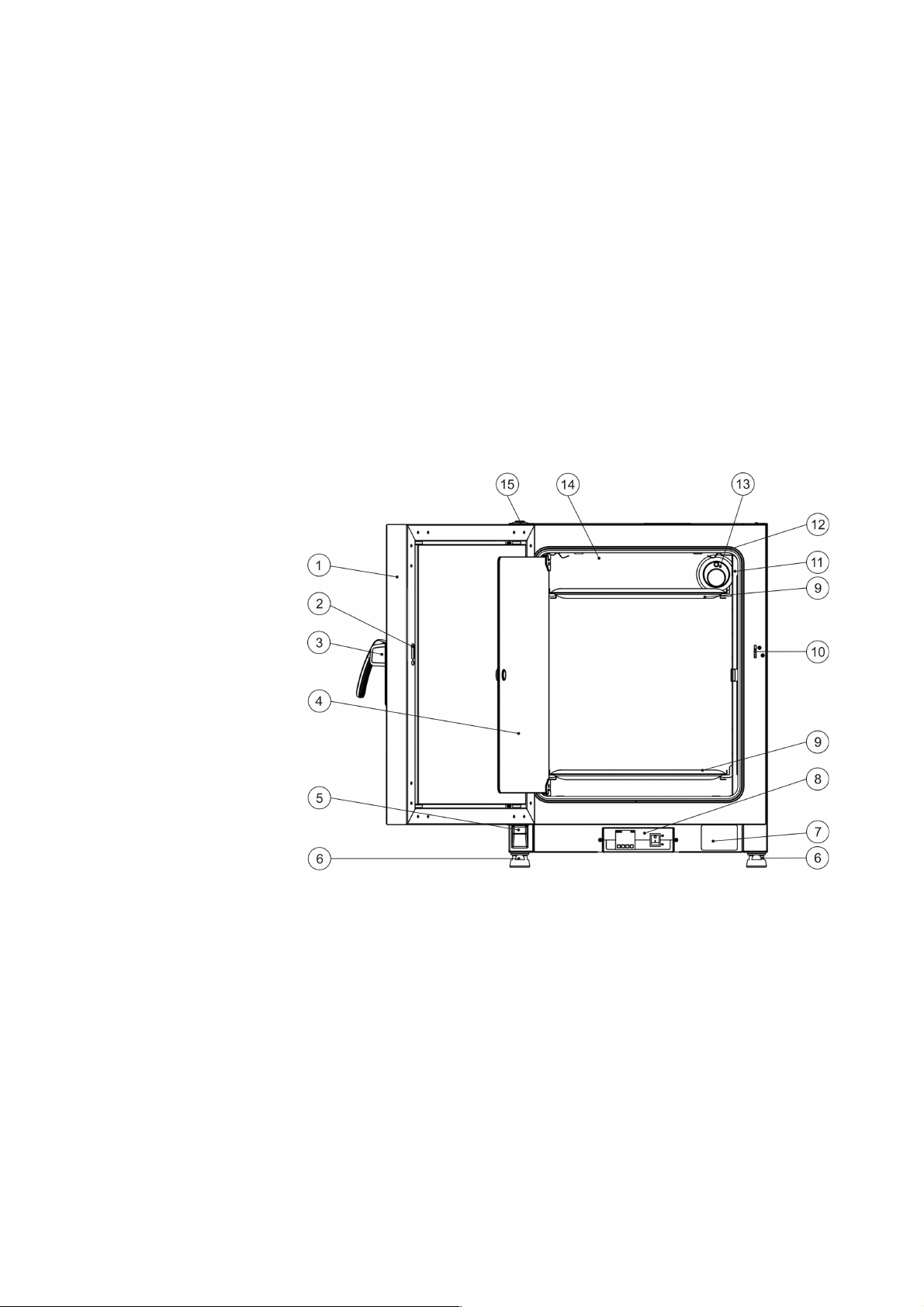
Figure 4-1. Fisherbrand Basic 60L/100L/180L Gravity Incubator Front View
[1] Outer door
[2] Door latch cutout
[3] Door latch and handle
[4] Glass door
[5] Door hinge, lower
[6] Leveling foot
[7] Nameplate
[8] Controller
[9] Perforated shelf
[10] Door hook catch
[11] Support rail for perforated shelf
[12] Door seal
[13] Access port
[14] Temperature sensor
[15] Door bearing
Fisherbrand 50152755 | 15
Page 22
Chapter 4
| Product Description
Safety Devices
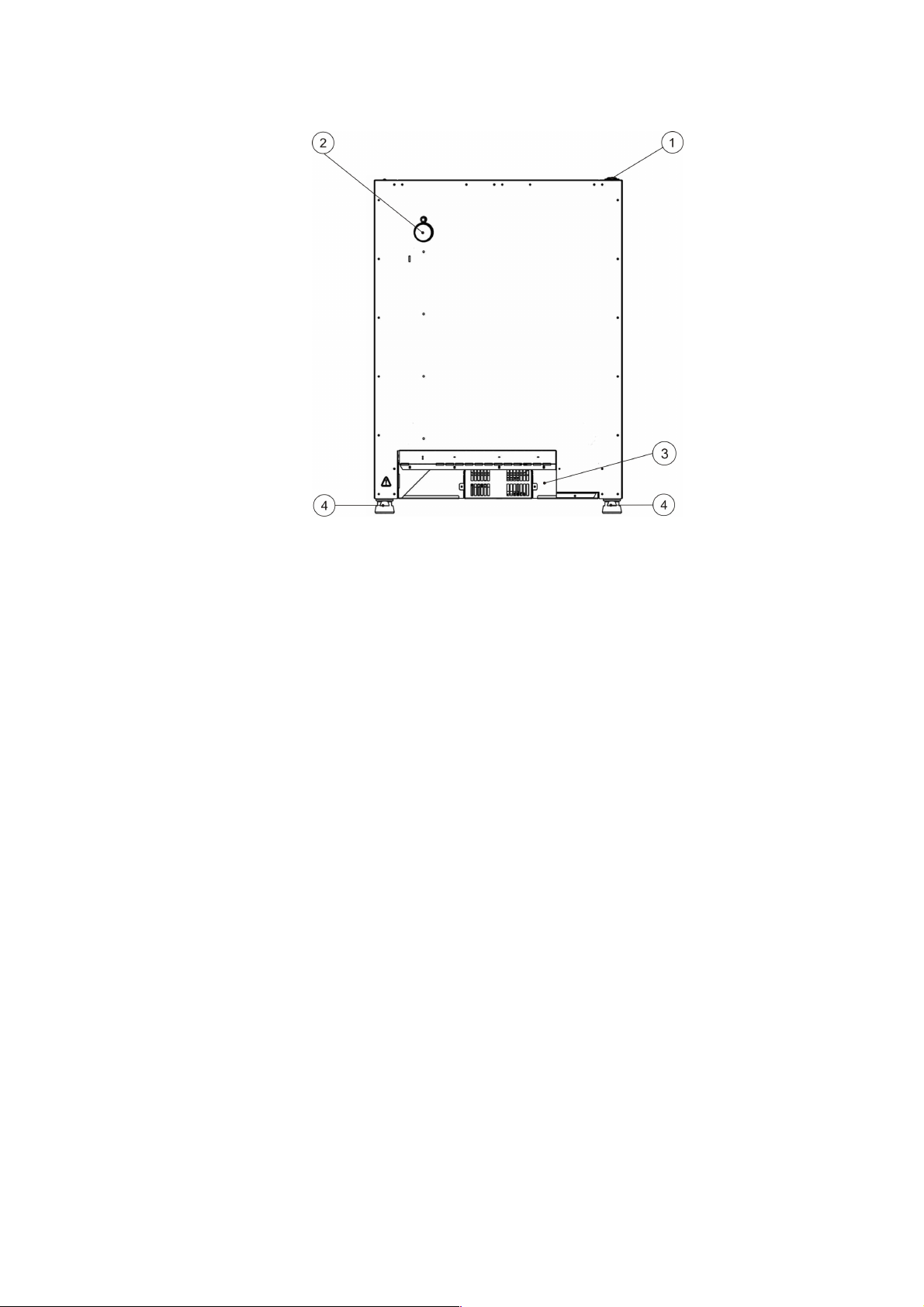
Figure 4-2. Fisherbrand Basic 60L/100L/180L Gravity Incubator Rear View
[1] Door bearing
[2] Access port
[3] Electronics compartment
[4] Leveling foot
The incubators are equipped with the following safety features:
an overheat protection cut-out feature that shuts down the
incubator
completely when
excessive temperatures occur in the workspace;
dual fuses rated at 16 amperes.
Work Space Atmosphere
To ensure undisturbed operation, the ambient temperature in the operating room must be at least
18 °C (64.4 °F).
The heating system uses this temperature threshold to control the ambient temperature plus 7 °C
(12.6 °F) up to the maximum of 75 °C (167 °F) for gravity convection incubators.
16
|
50152755 Fisherbrand
Page 23
Product Description |
1
Chapter 4
Sensing and Control System
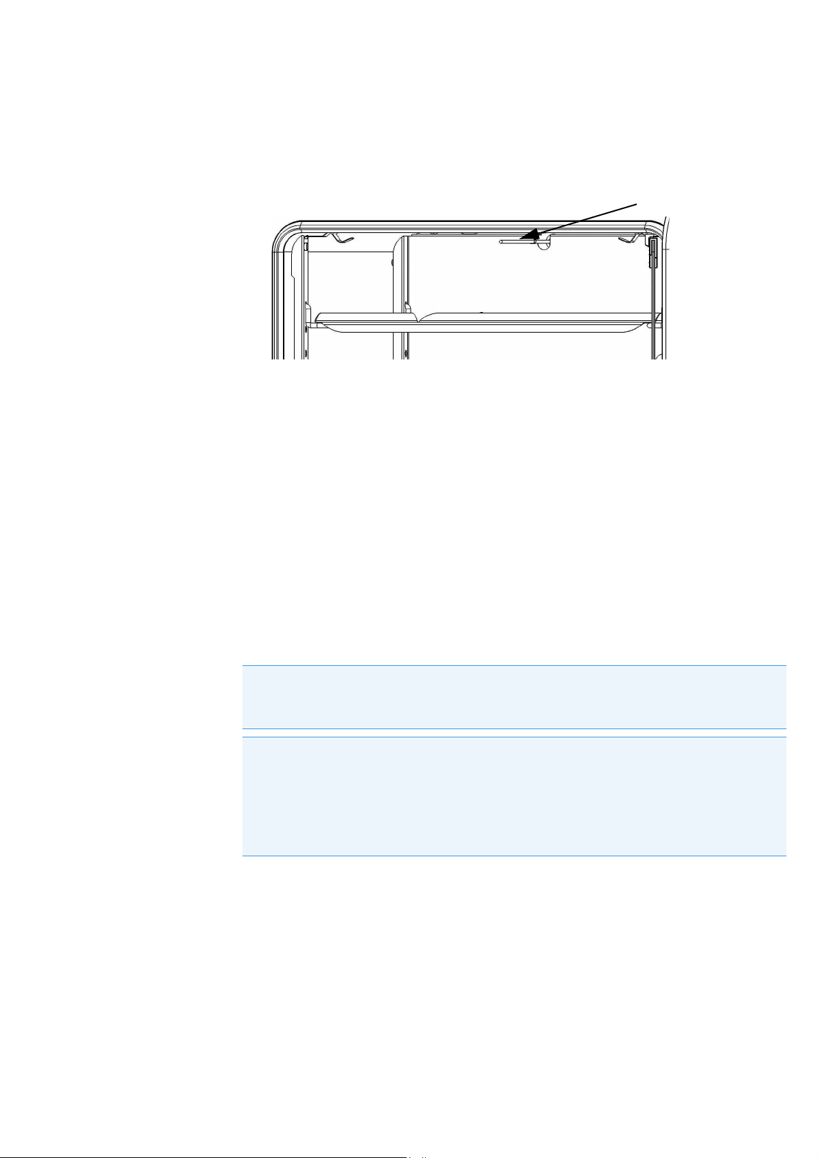
The PT 100-type sensor for the control of the work space temperature and for the thermal
protection [1] is installed on the top of the inner chamber.
Figure 4-3. Sensor System
The work space temperature sensor provides the inputs to the incubator’s built-in controller,
which continuously compares the measured values to the user-specified set value and adjusts the
heaters according to the result.
AC Power Socket
The incubator is connected to the AC supply mains via the socket (item 4 in Figure 4-4), which
accepts a power cord with an IEC standard plug.
Fuses
Two 16 A slow-blow fuses (T 16A H 250 V) mounted on the incubator’s main electronic circuit
board protect internal circuitry from the impact of excessive power consumption.
NOTE
Replacement should only be carried out by skilled and authorized qualified personnel of
electro technology/signal engineering!
NOTE
Fuse replacement
The device fuses are not user-serviceable. When the incubator exhibits the typical signs of
a blown fuse (no response to pressing the On/Off button, control panel remains
extinguished, no heating operation), call Fisher Scientific Customer Service to have the
fuses replaced.
Fisherbrand 50152755 | 17
Page 24
Chapter 4
| Product Description
Work Space Components
Inner Chamber
All components of the work space are made of corrosion-resistant stainless steel and have an
absolutely smooth and easy-to-clean surface. Any embossings have a large radius.
Access Port
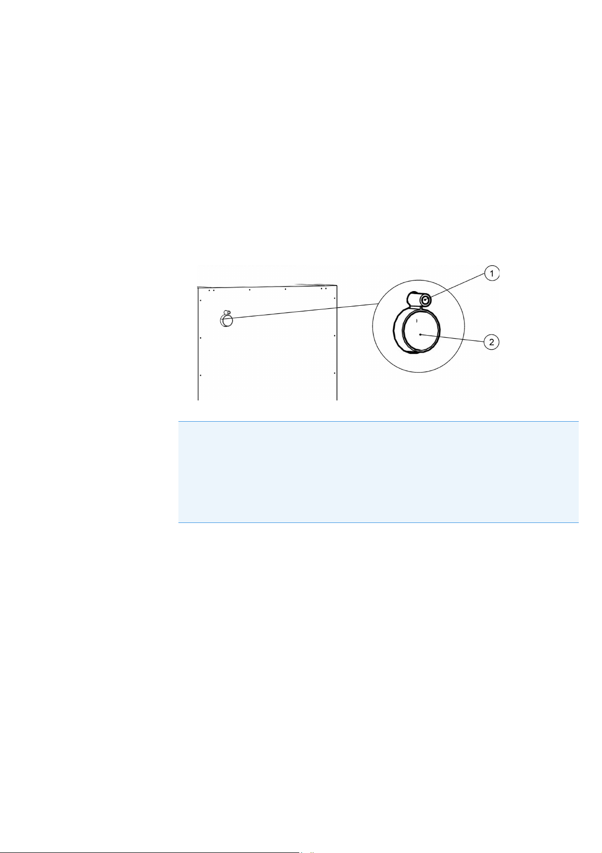
A re-sealable, capped access port (can be closed off using the plugs delivered with the unit)
allows cables, hoses or additional sensor leads to be routed into the work space of the incubator.
The small access port [1] is secured with a membrane. Cut off before use.
The main access port [2] has a diameter of 42 mm/1,65 inch.
NOTE
Operating conditions
When accessories are to be operated in the work space of the incubator, the ambient
condition requirements must be observed. The energy introduced into the work space has
an impact on the lower end of the temperature control range. When additional heating
sources are introduced into the work space, temperature control may be adversely
affected.
18
|
50152755 Fisherbrand
Page 25
Product Description |
Chapter 4
Shelf System
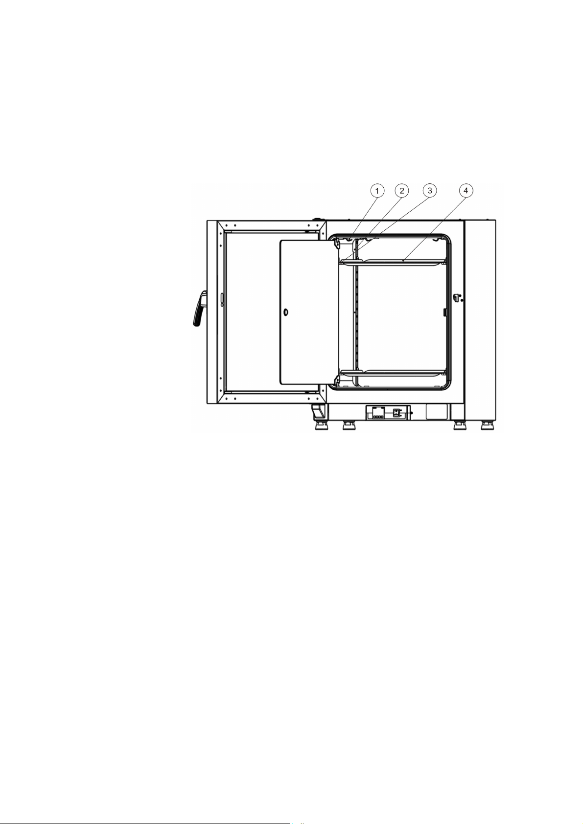
The incubator is supplied with two perforated shelves. The shelf support rails [1] have an
alternating pattern of oblong and round perforations spaced evenly at 30 mm, allowing the shelf
support brackets [8] to be inserted without any room for error, yet in a very flexible way to
accommodate any required height of sample container. The shelves [2] have an integrated tilt
protection and pull-out stop. For details on using the shelf system, see “Installing the Shelf
System” on page 21.
[1] Retaining Springs
[2] Support Rails
[3] Shelf Support
[4] Shelves
Figure 4-4. Basic Gravity Incubator Shelf System
Fisherbrand 50152755 | 19
Page 26

Chapter 4
| Product Description
20
|
50152755 Fisherbrand
Page 27
Start-up
Installing the Shelf System
The installation of the shelf system does not require any tools. The support rails are secured in
place by spring action. Once the shelf support have been inserted into the rails, the perforated
shelves can be simply pushed onto their support hooks to complete the installation.
Initial Installation
1. Peel off the protective foil from the support rails.
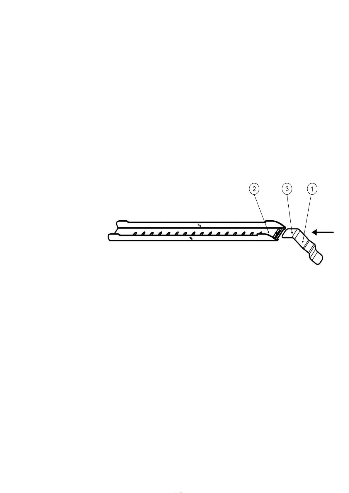
2. Push the retaining spring [1] into the guide on the support rail [2], making sure that the
locking nub [3] on the retaining spring safely engages with the matching hole in the support
rail.
.
Figure 5-1. Sliding the Retaining Spring into the Support Rail
Fisherbrand 50152755 | 21
Page 28
Chapter 5
| Start-up
Preparing the Work Space
Upon delivery, Fisherbrand incubators are not in a sterile state. Before the initial start-up, the
incubator must be decontaminated.
The following work space components should be checked for cleanliness and disinfected prior to
use:
support rails,
shelf support,
perforated shelves,
work space surfaces,
work space seals and gaskets,
glass door
NOTE
Disinfection
For details about the cleaning and disinfection of the incubator, please refer to “Cleaning
and Disinfection” on page 35.
Installation of the Support Rails
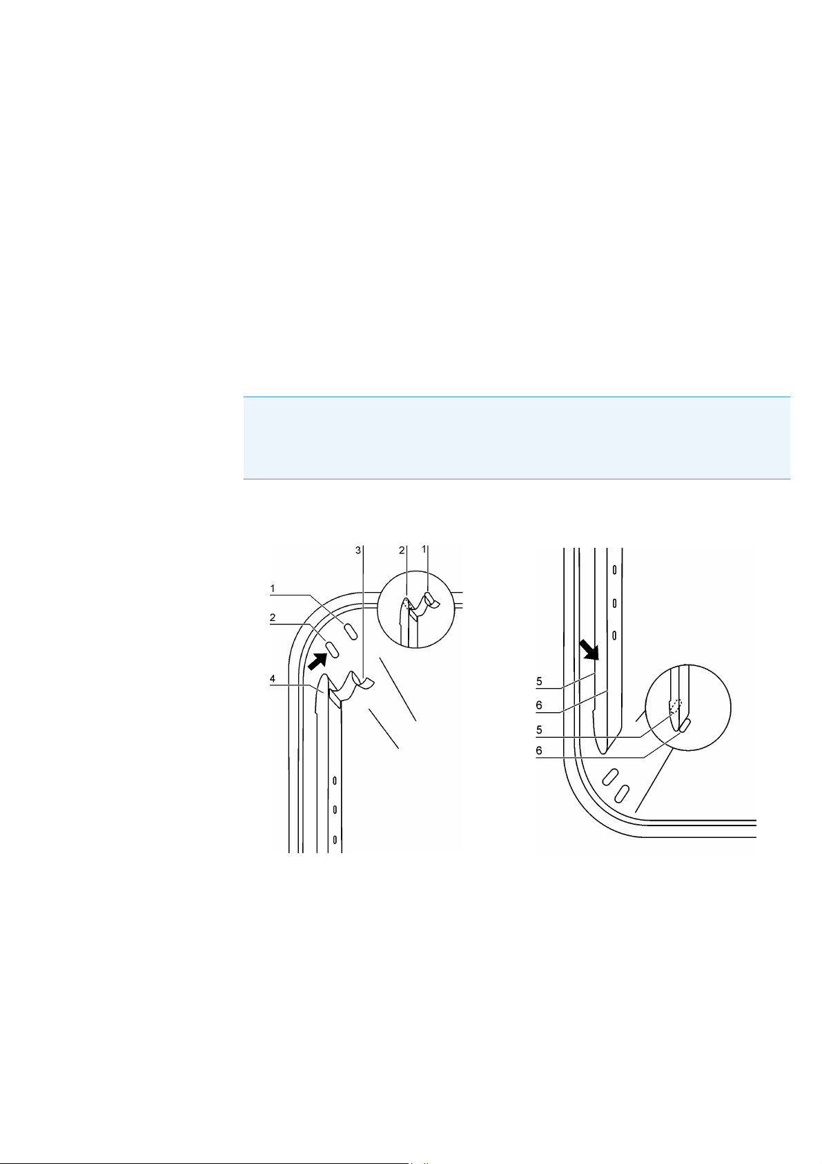
Figure 5-2. Support Rail Installation
The embossings at [2] and [5] act as lateral guides for the support rails, while the embossings at
[1] and [6] secure the support rails in place. For the support rails to install correctly the retaining
spring [3] must be facing upwards.
1. Place the support rail [4] on the lower embossing [6] and tilt it upwards against the work
space side wall so that the rail is positioned over the two embossings at [5] and [2].
2. Clamp the retaining spring [3] behind the upper embossing [1].
3. To remove the support rails, pull the retaining spring tab down out of the embossing and remove
the support rail assembly.
22
|
50152755 Fisherbrand
Page 29
Start-up |
Chapter 5
Installing the Shelf Support Brackets
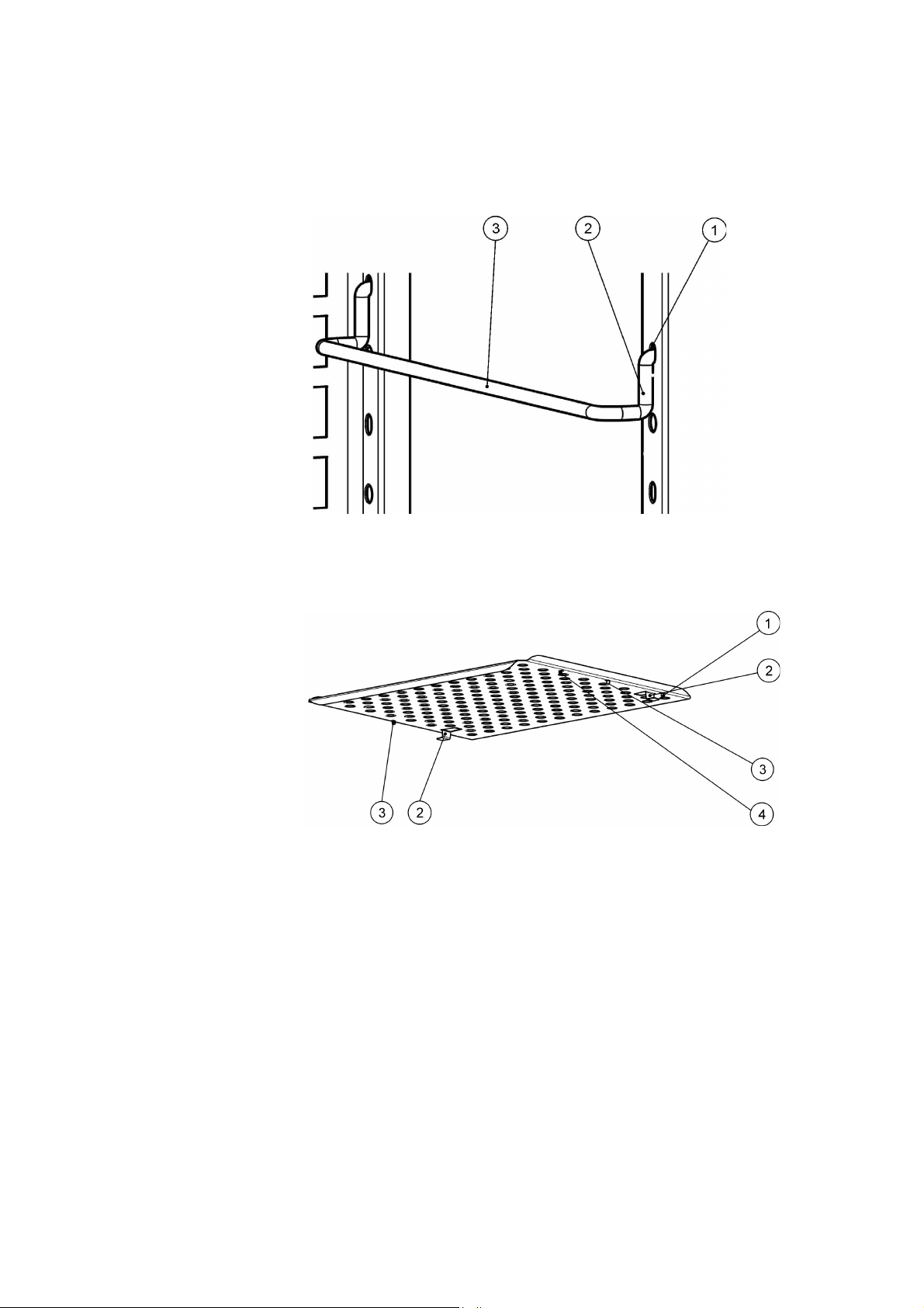
1. Insert the shelf support [3] into the perforations [1] of the support rail and tilt it downwards.
2. Make sure that the two vertical elements [2] of the shelf support butt against the support rail.
Figure 5-3. Shelf Support Installation
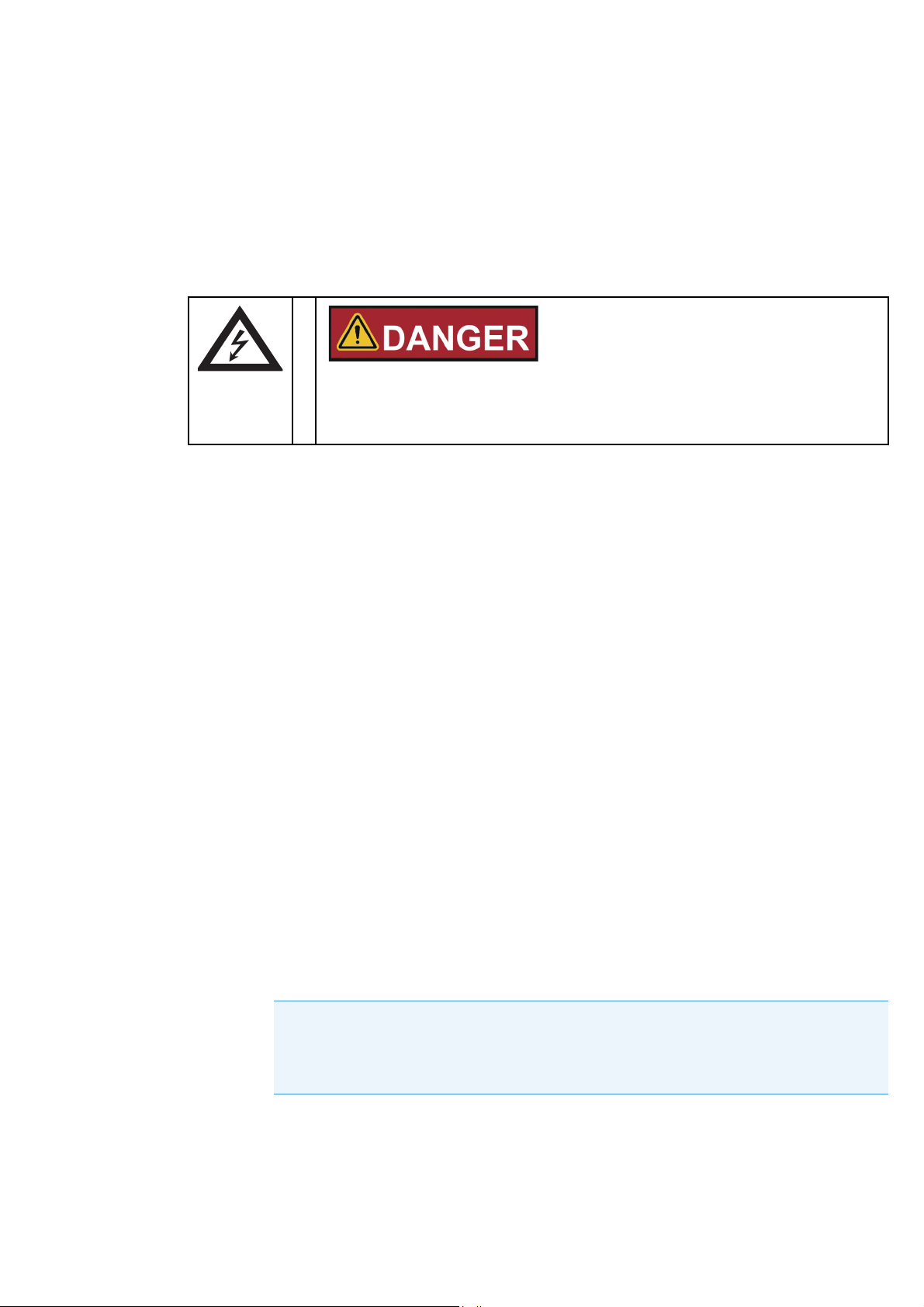
Installing the Perforated Shelves
[1] Rear Pull-out Stop
[2] Anti-tilt anchor
[3] Front Pull-out Stop
[4] Shelf
Figure 5-4. Installing the Perforated Shelves
1. Push the shelf [4] onto the shelf support with the tilt protection devices [2] facing the rear
panel of the incubator.
2. Slightly raise the perforated shelf so that the pull-out stops [1] and [3] can slide over the shelf
support.
3. Make sure that the shelves and both of their tilt protection devices are free to move over the
shelf support.
Fisherbrand 50152755 | 23
Page 30
Chapter 5
| Start-up
Levelling the Incubator
1. Position a bubble level onto the center shelf.
2. Manually adjust the leveling feet until the shelf is horizontally aligned in all directions. Perform
the adjustment of the leveling feet from left to right and from rear to front.
Connecting Power
Electric shock
Contact with live electrical components may cause a lethal electric shock. Before
connecting the incubator to the power supply, check the power cord and the plug for
damage. Do not use damaged cables for connecting the incubator to the power supply!
The incubator has a class I, protection-earthed enclosure. To minimize the risk of electrical shock,
use the AC power cord supplied to connect the incubator to a correctly installed and
protection-earthed power supply source, with the following features in place for each incubator:
T 16 A slow-blow fusing
B 16 circuit breaker
FI circuit breaker
Connecting to the Power Supply Source
1. Before connecting the incubator to the power source, check to see if the power supply
voltage corresponds with the specifications on the nameplate on the front of the incubator. If
the voltage (V) and current (A) ratings given are not as required, do not connect the incubator
to the power source!
2. Connect the IEC connector to the socket at the rear of the incubator.
3. Route the power cord along a path that does not cross exhaust air piping or passageways
and aisles.
With stacked devices, keep the power cord away from hot spots on the other incubator in the
stack.
4. Connect the protection-earthed plug of the power cord to a correctly protection-earthed and
earth leakage circuit breaker fused power socket.
5. Make sure the power cord is not subjected to tensile or compressive force.
NOTE
Keep the power outlet accessible!
To allow a rapid disconnection of power in case of an emergency, make sure that power
outlets remain freely accessible at all times!
24
|
50152755 Fisherbrand
Page 31

Start-up |
NOTE
Condensation
When taking the incubator into operation for the first time allow some time before
switching on for stabilization to avoid condensation forming on live parts.
If a high-voltage test is to be performed on the unit, it must first be heated for around 30
minutes at 75°C.
Chapter 5
Electrical Requirements to be Met when Operating the Incubators in the European Union:
The incubators are designed to operate on an AC mains having a maximum system impedance
Zmax = 0.321 Ohms, as measured at the system transfer point according to EN 61000-3-11,
paragraph 6.2.2. The user must ensure that the device is operated on a mains that complies with
this requirement. Where necessary, it is recommended to have the system impedance confirmed
by the power utility company.
Fisherbrand 50152755 | 25
Page 32

Chapter 5
| Start-up
26
|
50152755 Fisherbrand
Page 33
Operation
Preparing the Incubator
The incubator must not be released for operation before all major start-up activities have been
completed (see Chapter 5, “Start-up.” ).
Device Check
Prior to starting operation, the following incubator components must be checked for their correct
function:
The door seal in the front frame must not be damaged.
The glass door must not be damaged.
The shelving components must be installed safely.
Disinfecting the Incubator’s Work Space
Disinfect the work space according to the operator-specified hygiene guidelines.
Starting Operation
1. Turn the incubator on using the control panel.
2. Adjust the temperature set value on the control panel.
3. The temperature controller starts adjusting the work space to the user-specified temperature
set value now.
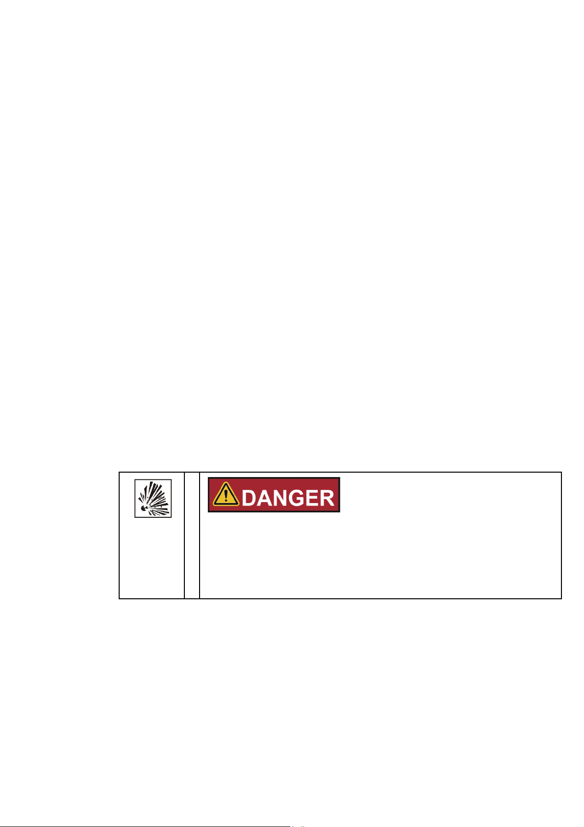
To avoid any risk of explosion or fire
• refrain from loading the incubator with any of the substances listed in the section
“Incorrect Use” on page 5
• make sure that the ambient air is free of any solvents
• do not operate the incubator in areas with an explosion hazard
Fisherbrand 50152755 | 27
Page 34
Chapter 6
| Operation
4. After the preset temperature is reached load the work space with samples.
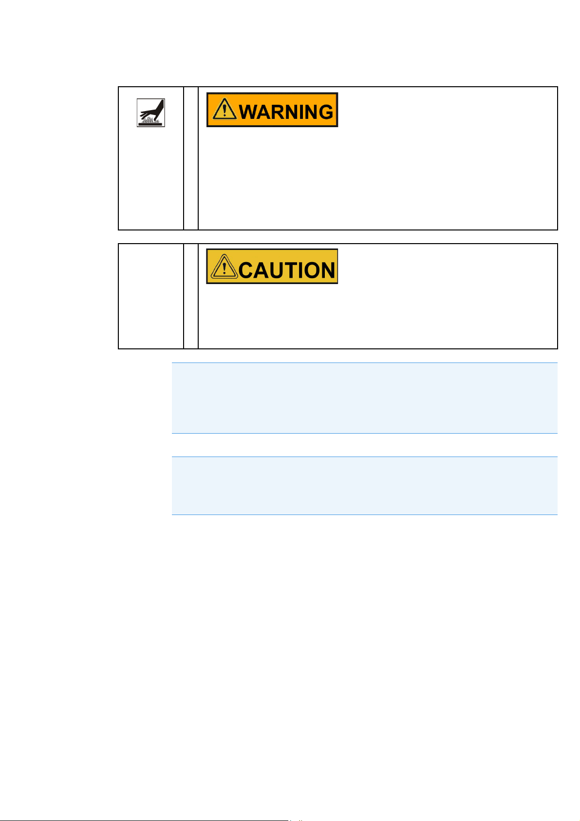
Hot surfaces
The screen of the glass door, the interior panel of the outer door as well as the
surfaces of the shelving and the work space become hot while the incubator is
running through its heating cycles and need some time to cool down.
When removing samples from a running or recently completed heating cycle, always
wear safety gloves and other appropriate personal protection equipment to avoid
burns on hot surfaces!
Risk of overloading
Overloading may damage the shelves or cause the shelves and/or the incubator to tilt
when the shelves are being drawn out, ultimately destroying the samples. To avoid
overloading the incubator or its shelving be sure to observe the sample weight limits
specified in Chapter 13, “Technical Data.”
NOTE
Proper loading
To ensure sufficient air circulation and uniform heating of the samples, do not use more
than 70% of the maximum surface area of the work space. Bulky objects in the work
space that dissipate heat may impair heat distribution.
NOTE
Door opening
Keep the door open-times during operation always as short as possible. The longer the
door is open, the higher can be a possible overshooting of the temperature.
28
|
50152755 Fisherbrand
Page 35
Handling and Control
Overview
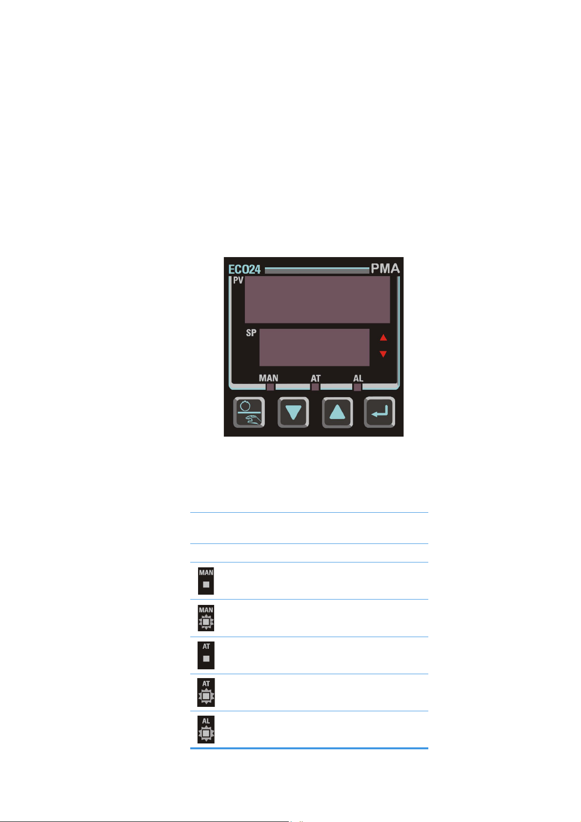
Fisherbrand basic gravity incubators come with a front panel mounted control unit consisting of a
multi-functional display, four control buttons, and an on/off button. The four control buttons
interact with the display window to let users access all of the user control functions and
adjustments of the incubator.
The graphic below shows the control panel with all of its visualization elements and controls.
Figure 7-1. Control Panel for Fisherbrand Basic Gravity Incubator
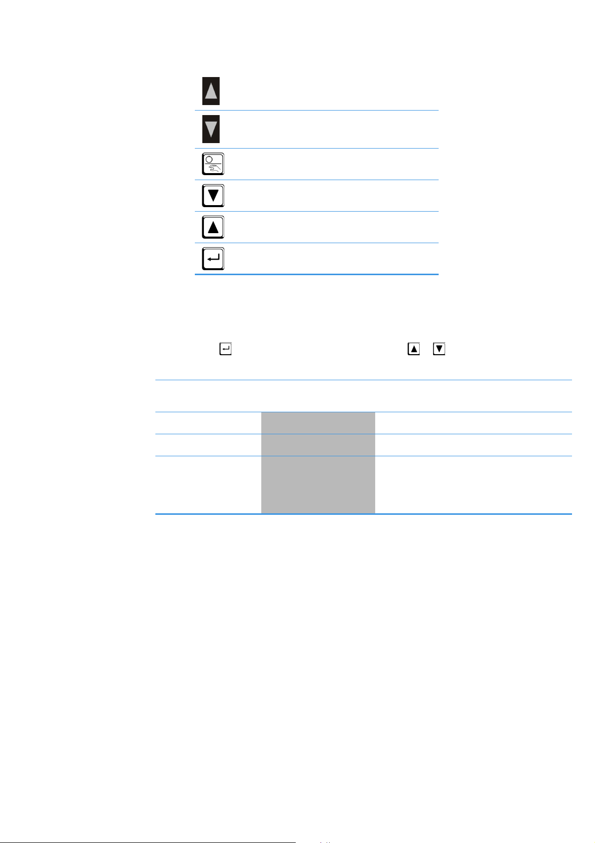
The table below contains brief descriptions of the buttons on the control panel.
Area/Button Description
PV Display Process variable - Actual value
during normal operation
SP Display Setpoint value
For internal use only
For internal use only
For internal use only
For internal use only
Blinking: Alarm active
Fisherbrand 50152755 | 29
Page 36
Chapter 7
| Handling and Control
ON: Controller output power up
For internal use only
For internal use only
Down button
Up button
Function button (scroll button)
Operator mode
This mode is entered at power on.
Press to scroll through the parameters, then press or to set the required value.
Upper Display Lower Display Description
PV Value Active SP Value PV (measuring value) and target value of
selected SP (setpoint)
SP Value
Active Alarms
Offset
SP
AlSt
OFFS
Setpoint value
Process variable only. Read only
Enables the adjustment of the temperature
offset. The adjusted value will be added to
the displayed actual temperature (PV-value).
This can be used to calibrate the incubator.
30
|
50152755 Fisherbrand
Page 37
Handling and Control |
Before
37.1
37.0
offset 1.5 °C
then
37.0
38.6
Chapter 7
Calibration of the reference sensor
The temperature measurement for calibration is performed with a reference sensor placed in the
center of the inner chamber.
After placing the reference sensor in the chamber wait at least 2 hours until the temperature is
stabilized.
In operator mode the temperature offset can be adjusted.
Calibration parameters
Only trained personnel should perform the calibration.
Be aware that initial calibration parameters are not stored!
Adjustment of the temperature offset:
Press 2 x to scroll to the offset input OFFS.
If an alarm is displayed the button must be pressed 3x.
Press or to set the required value in 0.1 °C steps.
Acknowledge the entry with or wait approx. 2 min for automatically storage of the value.
The new temperature is adjusted.
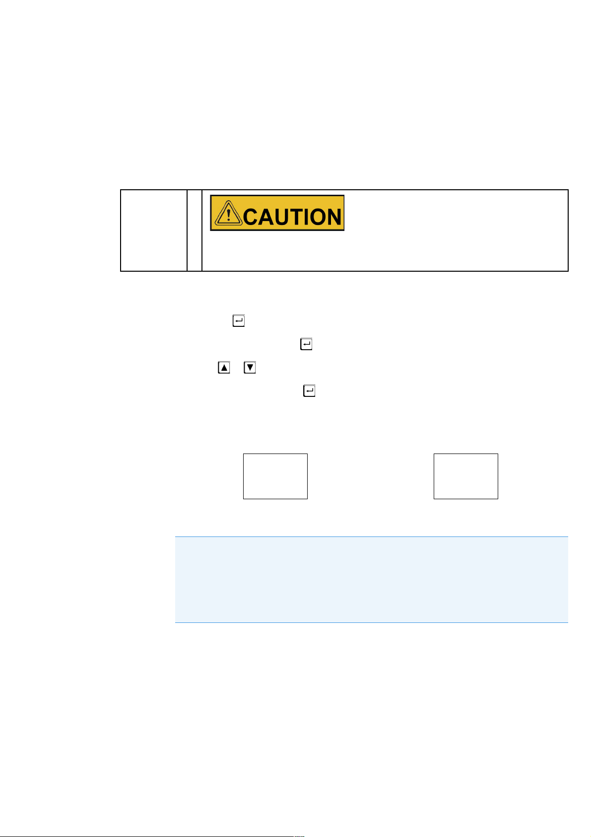
For example:
The controller adds the adjusted offset to the measured value on the display.
NOTE
Entering an offset value more than 2 °C, an alarm is indicated and is present as long as the
readjustment takes.
Only 1 offset value can be entered. The entered offset value is valid for the complete
temperature range. This means, if the setpoint temperature is changed the same offset
value remains.
Fisherbrand 50152755 | 31
Page 38

Chapter 7
| Handling and Control
32
|
50152755 Fisherbrand
Page 39
Shut-down
Shutting the Incubator Down
This chapter provides instructions for shutting the incubator down for prolonged periods of time,
that is, at least for several days in a row.
Contamination hazard
If the work space surfaces are contaminated, harmful biological material may spread
to the environment of the incubator.
To rule out any risk for subsequent users, perform a full cleaning, disinfection and
decontamination cycle to the standards set out in the section “Cleaning and
Disinfection” on page 35 if you suspect (or if you are positive) that harmful biological
material has been processed with the incubator.
1. Remove the containers with the cultures, all accessories, and other objects from the work
space.
2. Clean and disinfect the work space, as explained in the section “Cleaning and Disinfection”
on page 35.
3. Before cleaning and disinfection and/or decontamination, turn the incubator off using the
control panel.
4. Unplug the power cord and secure it against accidental reconnection.
5. Until the incubator is shut down, the work space must be continuously ventilated. Leave the
glass door and the outer door open and secure them against accidental closure.
Fisherbrand 50152755 | 33
Page 40

Chapter 8
| Shut-down
34
|
50152755 Fisherbrand
Page 41
Cleaning and Disinfection
Cleaning
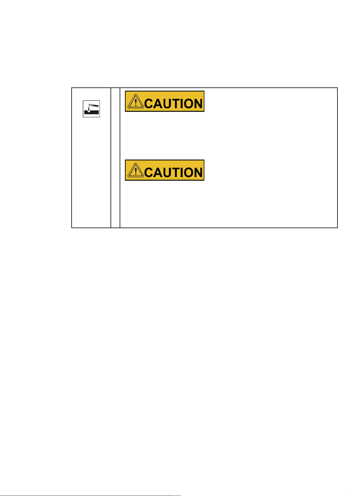
Some incubator components are made of plastics. Solvents may attack plastics.
Strong acids or alkaline solutions may cause embrittlement of plastics.
Please consult the manufacturer or his agent if there is any doubt about the
compatibility of decontamination or cleaning agents.
Do not spray cleaning agent onto the control panel and the interfaces at the rear of the
incubator. When wiping the incubator clean, always make sure that no moisture enters
into these components.
Wipe the display window down with a slightly dampened cloth, then wipe dry with a
rag made of 100% microfiber.
Incompatible cleaners
Moisture-sensitive components
Cleaning Exterior Surfaces
Remove dirt residues and depositions thoroughly using a solution of lukewarm water and
commercial detergent.
Wipe the surfaces clean using a clean cloth and clear water.
Then, wipe the surfaces dry using a clean cloth.
Wipe / Spray Disinfection
The manual wipe and spray disinfection is a three-stage process:
predisinfection,
cleaning,
final disinfection.
Fisherbrand 50152755 | 35
Page 42
Chapter 9
| Cleaning and Disinfection
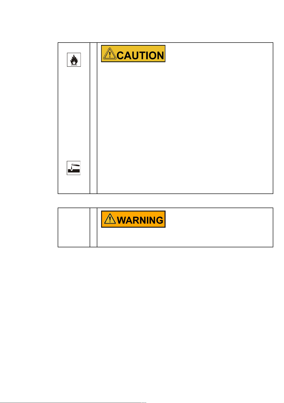
Alcoholic disinfectants!
Disinfectants having an alcohol content of more than 10% may form, in combination
with air, easily combustible and explosive gas mixtures.
When using such disinfectants, avoid open flames or exposure to excessive heat
during the entire disinfection process!
Use such disinfectants only in adequately ventilated rooms.
After the disinfectant has been allowed to react, wipe the cleaned incubator
components thoroughly dry.
Observe safety regulations to avoid fire and/or explosion hazard caused by
alcohol-containing disinfectants.
Chloride-containing disinfectants!
Chloride-containing disinfectants can corrode stainless steel.
Use only disinfectants that do not affect stainless steel!
Decontamination or cleaning agents
Thermo Electron LED GmbH or his agent is to be consulted if there is any doubt about
the compatibility of decontamination or cleaning agents.
36
|
50152755 Fisherbrand
Page 43
Cleaning and Disinfection |
Preparing the Manual Wipe/Spray Disinfection
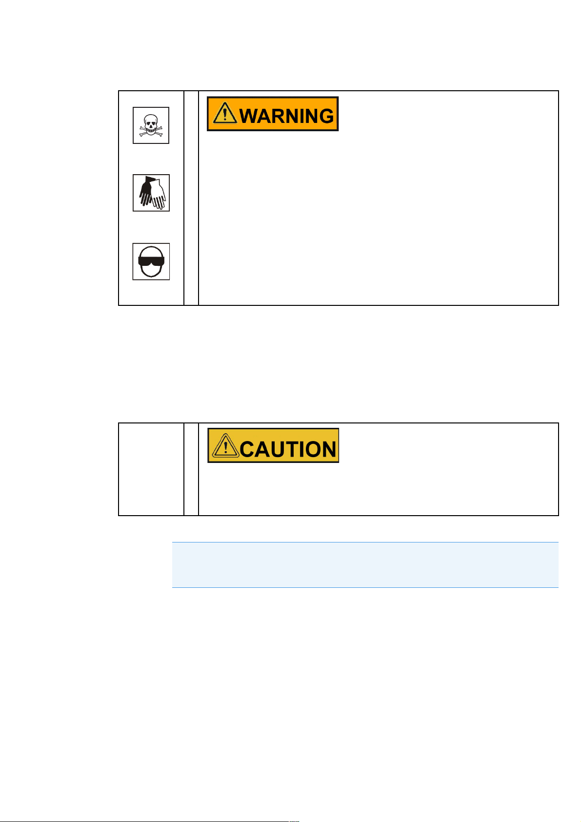
Health hazard
The surfaces of the work space may be contaminated. Contact with contaminated
cleaning liquids may cause infections. Disinfectants may contain harmful substances.
When cleaning and disinfecting, always observe the safety instructions and hygiene
guidelines!
• Wear safety gloves.
• Wear safety goggles.
• Wear mouth and respiratory system protection gear to protect your mucous membranes.
Observe the safety instructions of the disinfectant’s manufacturer and the hygiene
supervisor.
Chapter 9
Predisinfection
1. Remove all samples from the work space and store them in a safe place.
2. Turn the power switch off.
3. Spray disinfectant onto the surfaces of the work space and of the accessories or wipe the
surfaces clean using disinfectant.
Risk of injury caused by breaking of glass panel
The glass panel may only be removed by properly trained and authorized specialists.
The glass panel must be held by two persons.
4. Allow time for the disinfectant to act as specified by the manufacturer.
NOTE
Disinfecting hard-to-reach components
Spray the sensor and other hard-to-reach components with disinfectant!
Cleaning
1. Remove all internals from the specimen chamber.
2. Wipe off the specimen chamber surfaces and the internals that have been removed from the
chamber using lukewarm water mixed with standard rinsing agents. Completely remove any
tenacious impurities using rinsing agent and warm water.
3. Re-rinse the cleansed surfaces 3 to 5 times with autoclaved water to completely remove and
cleaning agent residues.
4. After this, wipe the cleansed surfaces and internals dry with a soft, sterile cloth.
Fisherbrand 50152755 | 37
Page 44
Chapter 9
| Cleaning and Disinfection
Final Disinfection
1. Spray the specimen chamber surfaces and the internals removed from this chamber again
with disinfectant, or wipe them down.
2. Let the disinfectant work on the surfaces/internals as detailed in the manufacturer’s
instructions.
3. Re-install the internals in the specimen chamber.
NOTE
Recommendations for decontamination
The user should be familiar with the internationally recognized “Laboratory Biosafety
Manual” (from the World Health Organization (WHO)) and with national, pertinent
recommendations. These manuals/recommendations provide information about
decontaminants, their use, dilution, properties and possible applications.
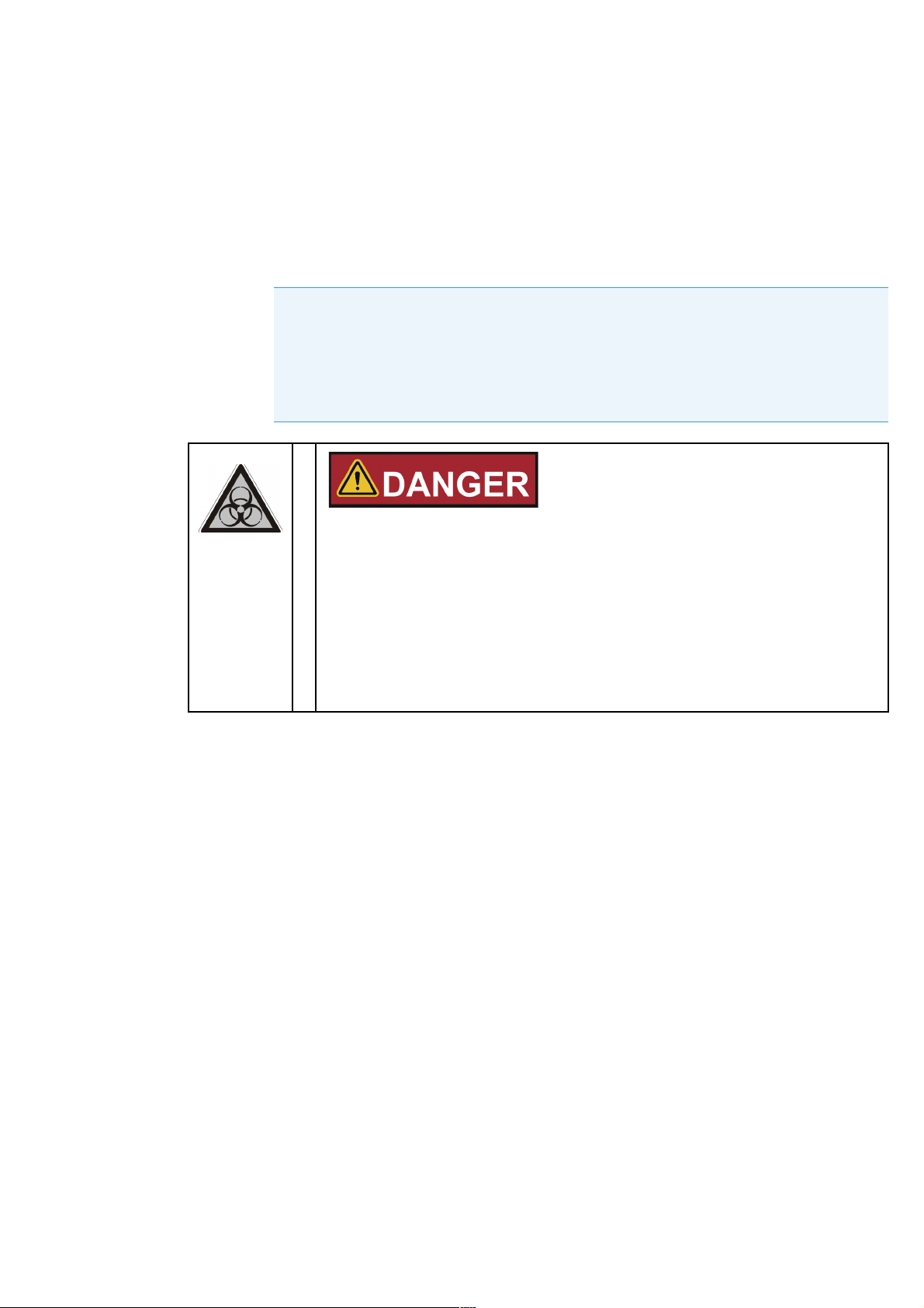
Bio-hazard
Be sure to determine the current operating condition of the incubator before you open
the door!
Under specific circumstances, there is a risk that bacteria, viruses, fungi, prions, and
other biological substances survive.
Decontamination must be performed immediately if any biohazardous material is
spilled in or on the incubator.
38
|
50152755 Fisherbrand
Page 45
Maintenance
Maintenance and inspection at regular intervals of the features and components listed below are
mission-critical to maintain the product in a fully operative and safe condition and avoid malfunctions
due to aging and wear. Failure to perform maintenance on a regular basis may result in:
deviations in heating performance
damage to samples
loss of control over temperature distribution throughout the work space
Inspections and Checks
To ensure the operational performance and safety of the incubator and its functions, the
components listed below must be checked at regular intervals.
Regular Checks
Check the incubator for overall cleanliness and remove any residues from previous processes.
Check the locking screw for the glass panel
Semi-annual Inspection
Check integrity and proper seating of the seal.
Perform functional check of the control panel and of the incubator’s built-in controller.
Perform electrical safety check in accordance with the relevant national regulations
NOTE
Functional check
If safety devices were removed or disabled for inspections, the incubator must not be
operated before the safety devices have been reinstalled and checked for their correct
function.
Spare Parts and User Modifications
To avoid major malfunctions of the incubator and associated safety hazards that may
result in death, serious injuries, or damage to the incubator and other equipment, use
spare parts approved by Fisherbrand only. Third-party spares without Fisherbrand
approval void the limited warranty.
.
Do not modify the incubator in any way without obtaining the prior written
authorization from Fisherbrand. Unauthorized modifications may compromise
operational safety and give rise to hazards that may result in death, serious injuries, or
damage to the incubator and other equipment.
Fisherbrand 50152755 | 39
Page 46

Chapter 10
| Maintenance
Service Intervals
During running operation, the following service works must be performed:
3-monthly service
Perform the comparative temperature measurement outlined in section 7-3.
Annual Service
Have the incubator inspected and services by a Fisherbrand authorized Technical Service agent.
NOTE
Service contract
Fisherbrand International, LLC offer a product-specific service contract comprising all
necessary tests and service work.
40
|
50152755 Fisherbrand
Page 47
Maintenance |
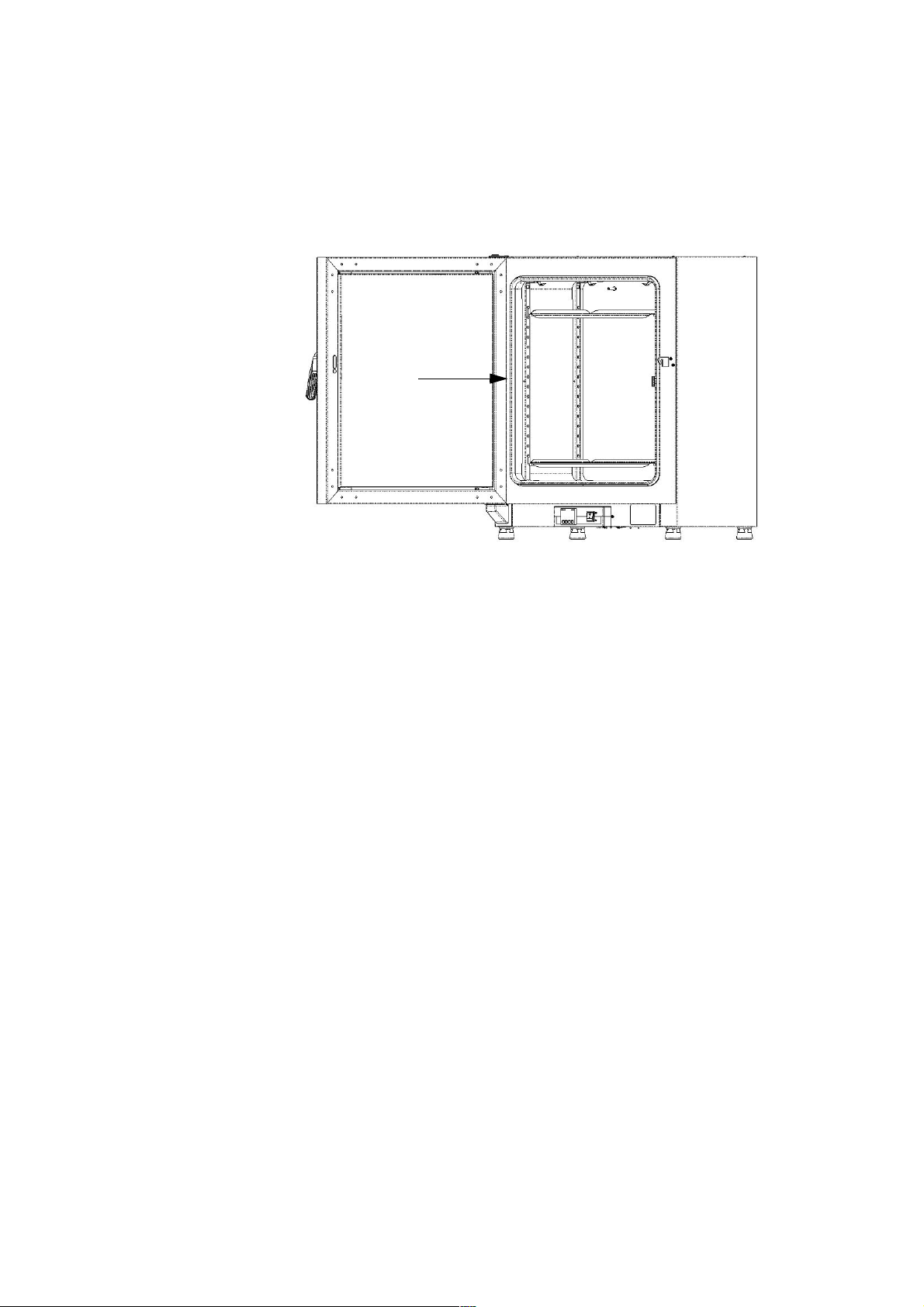
Replacing the Door Seal
The door seal of the outer door is located in the retaining slot.
The door seal should be inspected for any signs of embrittlement at half-yearly intervals.
No tools are required to replace the seal.
Chapter 10
Figure 10-1. Door seal
1. Pull the seal out of the guide slot.
2. Starting on the hinge side of the door, position the end of the new seal at the location
indicated by the arrow in Figure 10-1 above.
3. Gently press the seal into the slot, working around the circumference of the door. In corner
areas in particular ensure that the seal lip is installed without any wrinkles and that the seal is
not stretched or compressed.
4. Make sure that the seal is positioned correctly in the slot and flush with the door frame.
Correct, if necessary.
Replacing the Power Cord
If the power cord is damaged, it must be replaced by an original spare part. Using a standard
power cord with a lower thermal withstand capabilities is prohibited.
Returns for Repair
Prior to returning any materials, please contact our Customer Service Department for a “Return
Materials Authorization” number (RMA).
Fisherbrand 50152755 | 41
Page 48
Chapter 10
| Maintenance
Material returned without an RMA number will be refused.
Contamination hazard
The incubator may have been used for treating and processing infectious substances,
which may have caused contamination of the incubator and its components.
Prior to return shipment, it is therefore mandatory that all incubator components be
properly decontaminated.
• Clean the incubator components thoroughly, then disinfect or decontaminate them
(depending on application).
• Fill in and attach a safety declaration with details on decontamination activities
performed to the items that are to be repaired.
42
|
50152755 Fisherbrand
Page 49
Disposal
Contamination hazard
The incubator may have been used for treating and processing infectious substances,
which may have caused contamination of the incubator and its components.
Prior to disposal, it is therefore mandatory that all incubator components be properly
decontaminated.
Clean the incubator components thoroughly, then disinfect or decontaminate them
(depending on application).
• Attach a declaration of decontamination with details on decontamination activities
performed to the items that are to be disposed of.
Overview of Materials Used
Component Material
Thermal insulation components Glass wool
Printed circuit boards Coated electrical components contain various plas-
tics materials. Components mounted on circuit
boards containing epoxy resin bonder.
Plastic components, general see material labeling
Exterior housing Galvanized steel sheet, painted
Device rear panel Galvanized steel sheet
Outer door Galvanized steel sheet, painted, + stainless steel
(optional)
Door inner panel Stainless steel
Control panel and display window protective
foil
Heater Silicone-sheathed resistance heater wires
Interior containers, installed components and
shelves
Door frame seal Silicone
Polyethylene
Stainless steel 1.4016 + 1.4301
Glass screen Sodium silicate glass
Cables Plastic-sheathed stranded copper wire
Packaging Corrugated board, polyethylene film, and styrofoam,
chemically untreated wood
Fisherbrand 50152755 | 43
Page 50

Chapter 11
| Disposal
44
|
50152755 Fisherbrand
Page 51
Error Codes
Table 1 below lists the error messages that may appear in the control panel display window and
provides instructions for clearing such alarms.
Parameter Upper Display Lower Display Description
Alarm Setpoint value An alarm LED indicates that the unit tem-
perature is 2°C above setpoint.
The controller is operating the incubator
back to set temperature.
If an alarm is indicated "AlSt 1!” is displayed after pressing twice the Enter button.
Sensor Break
OTP - Overtemperature protection
OPEN
cHH
>
Table 1. Error codes
Setpoint value Break in input sensor or wiring. Contact
Technical Service.
This code is displayed up to 105 °C, then
“OPEN” is displayed.
If the incubator does not heat, possibly an
activation of the OTP has occurred. In this
case the heater will remain off. Contact
Technical Service.
Fisherbrand 50152755 | 45
Page 52

Chapter 12
| Error Codes
46
|
50152755 Fisherbrand
Page 53

Technical Data
The technical data are valid only for an empty device equipped with three shelves, a spray-painted outer
enclosure and a power line voltage 120 V 60 Hz (Table 1) or 230 V 50/60Hz (Table 2). Options may have an
impact on the specified performance.
Table 1. Technical Data - Gravity Convection Incubators 120 V
Parameter Unit
Process
Work space atmosphere
Min.
Max.
Temperature deviation from set value at
37 °C (98.6 °F), spatial (*)
typical:
max.:
Temperature deviation from set value at 37 °C (98.6 °F),
over time (*)
Heat-up time (work space unoccupied, from 25 °C
(77 °F) to 98% of final temperature (*)
Recovery time (work space unoccupied, door open for
30 s, to 98% starting temperature. (*)
typical:
max.:
K
°C/°F
K ± 0.8
K ±0.3 ±0.3 ±0.3
min 80 80 80
min 8
Fisherbrand
Basic 60L
Gravity
Incubator
Ambient temperature plus
7 °C/12.6 °F
75 °C/167 °F
± 0.9
10
Fisherbrand
Basic 100L
Gravity
Incubator
Ambient
temperature plus
7°C/12.6°F
75 °C/167°F
± 0.8
± 0.9
10
12
Fisherbrand
Basic 180L
Gravity
Incubator
Ambient
temperature
plus
7°C/12.6°F
75 °C/167 °F
± 0.8
± 0.9
12
14
Heat dissipation to environment (at set temperature of
37 °C (98.6 °F) and room temperature of 25 °C/77 °F)
(*) all values measured with unoccupied working space and maximum 3 shelves
Overall dimensions
Height mm/in 720/28.3 820/32.3 920/36.2
Width mm/in 530/20.8 640/25.2 640/25.2
Depth mm/in 565/25.2 565/25.2 738/29.1
Overall weight kg/lbs 40/88 51/112 65/143
Loading capacity
Loading capacity per shelf kg/lbs 25/55
Max. overall loading capacity per device kg/lbs 50/110 50/110 75/165
Fisherbrand 50152755 | 47
W 21 ±10% 26 ±10% 31 ±10%
Page 54

Chapter 13
Table 1. Technical Data - Gravity Convection Incubators 120 V
| Technical Data
Parameter Unit
Fisherbrand
Basic 60L
Gravity
Incubator
Fisherbrand
Basic 100L
Gravity
Incubator
Fisherbrand
Basic 180L
Gravity
Incubator
Electrical data
Power consumption W 300 540 720
Maximum current A 2.5 4.5 6.0
Earthing system (e.g. 1/N/PE) 1/N/PE 1/N/PE 1/N/PE
Power line frequency Hz 50/60
Power line voltage +/- 10 % V 120
IP protection system IP 20
Protection class I
Overvoltage category II
Device fusing, building side A 16
Device fusing, on PCB (T 16A H 250 V) A 2 x 16
Environmental conditions
Min. ambient temperature °C/°F 18/65
Max. ambient temperature °C/°F 32/90
Max. humidity in service,
non condensing
% r.F./
% r.H.
80, non condensing
Min. storage temperature °C/°F 20/68
Max. storage temperature °C/°F 60/140
Max. humidity in storage, non condensing % r.F./
90, non condensing
% r.H.
Post-transport acclimation time h 2
Noise level dB(A) no Inherent noise
Pollution degree 2
Site conditions
Maximum altitude above sea level m/y NN 2000/2187
Minimum side clearance mm/in 50/2
Minimum front clearance mm/in 590 / 23.2 690 / 27.2 814 / 32
Minimum back wall clearance mm/in 80/3.2
Minimum bottom clearance mm/in 200/8
Minimum top clearance mm/in 300/12
48
|
50152755 Fisherbrand
Page 55

Table 2. Technical Data - Gravity Convection Incubators 230 V
Technical Data |
Chapter 13
Parameter Unit
Process
Work space atmosphere
Min.
Max.
K
°C/°F
Temperature deviation from set value at
37 °C (98.6 °F), spatial (*)
typical:
K ± 0.8
max.:
Temperature deviation from set value at 37 °C (98.6 °F),
K ±0.3 ±0.3 ±0.3
over time (*)
Heat-up time (work space unoccupied, from 25 °C
min 80 80 80
(77 °F) to 98% of final temperature (*)
Recovery time (work space unoccupied, door open for
30 s, to 98% starting temperature. (*)
typical:
min 8
max.:
Fisherbrand
75L Incubator
Ambient
temperature
plus
7 °C/12.6 °
F
75 °C/167 °
F
± 0.9
10
Fisherbrand
117L Incubator
Ambient temperature plus
7°C/12.6°F
75 °C/167°F
± 0.8
± 0.9
10
12
Fisherbrand
194L Incubator
Ambient
temperature
plus
7°C/12.6°F
75 °C/167 °F
± 0.8
± 0.9
12
14
Heat dissipation to environment (at set temperature of
W 21 ±10% 26 ±10% 31 ±10%
37 °C (98.6 °F) and room temperature of 25 °C/77 °F)
(*) all values measured with unoccupied working space and maximum 3 shelves
Overall dimensions
Height mm/in 720/28.3 820/32.3 920/36.2
Width mm/in 530/20.8 640/25.2 640/25.2
Depth mm/in 565/25.2 565/25.2 738/29.1
Overall weight kg/lbs 40/88 51/112 65/143
Loading capacity
Loading capacity per shelf kg/lbs 25/55
Max. overall loading capacity per device kg/lbs 50/110 50/110 75/165
Electrical data
Power consumption W 140 185 345
Maximum current A 0.6 0.8 1.5
Earthing system (e.g. 1/N/PE) 1/N/PE 1/N/PE 1/N/PE
Power line frequency Hz 50/60
Power line voltage +/- 10 % V 230
Fisherbrand 50152755 | 49
Page 56

Chapter 13
| Technical Data
Parameter Unit
Fisherbrand
75L Incubator
IP protection system IP 20
Protection class I
Overvoltage category II
Device fusing, building side A 16
Device fusing (T 16A H 250 V) A 2 x 16
Environmental conditions
Min. ambient temperature °C/°F 18/65
Max. ambient temperature °C/°F 32/90
Max. humidity in service,
non condensing
% r.F./
% r.H.
80, non condensing
Min. storage temperature °C/°F 20/68
Max. storage temperature °C/°F 60/140
Max. humidity in storage, non condensing % r.F./
90, non condensing
% r.H.
Post-transport acclimation time h 2
Fisherbrand
117L Incubator
Fisherbrand
194L Incubator
Noise level dB(A) no Inherent noise
Pollution degree 2
Site conditions
Maximum altitude above sea level m/y NN 2000/2187
Minimum side clearance mm/in 50/2
Minimum front clearance mm/in 590 / 23.2 690 / 27.2 814 / 32
Minimum back wall clearance mm/in 80/3.2
Minimum bottom clearance mm/in 200/8
Minimum top clearance mm/in 300/12
50
|
50152755 Fisherbrand
Page 57

Accessories
Material No. Description
150145852 Stainless steel perforated shelf for 60L/75L incubators, including 2 shelf supports
150145853 Stainless steel perforated shelf for 100L/117L incubators, including 2 shelf supports
150145854 Stainless steel perforated shelf for 180L/194L incubators, including 2 shelf supports
150145846 Wire mesh shelf for 60L/75L incubators, including 2 shelf supports
150145847 Wire mesh shelf for 100L/117L incubators, including 2 shelf supports
150145848 Wire mesh shelf for 180L/194L incubators, including 2 shelf supports
Fisherbrand 50152755 | 51
Page 58

Chapter 14
| Accessories
52
|
50152755 Fisherbrand
Page 59

Device Log
Incubator type: Part number:
Serial number: Service number:
Location Operator’s note:
Work carried out Notes Date Signature
Fisherbrand 50152755 | 53
Page 60

Chapter 15
| Device Log
54
|
50152755 Fisherbrand
Page 61

Austria: +43(0)800-20 88 40
Germany: +49 (0)2304 9325
Finland: +358 (0)9 8027 6280
Norway: +47 22 95 59 59
Sweden: +46 31 352 32 00
Belgium: +32 (0)56 260 260
Ireland: +353 (0)1 885 5854
France: +33 (0)3 88 67 14 14
Portugal: +351 21 425 33 50
Switzerland: +41 (0)56 618 41 11
Denmark: +45 70 27 99 20
Italy: +39 02 950 59 478
Netherlands: +31 (0)20 487 70 00
Spain: +34 902 239 303
UK: +44 (0)1509 555 500
 Loading...