

Fisher XLS 74800, XLS 74810, XLS 74850, XLS 79810, XLS 87800 Installation Instructions Manual
...
Fisher Engineering
74800, 74810, 74850
79810, 79850, 87800
50 Gordon Drive, Rockland, Maine 04841-2139 • www.fi sherplows.com
‡
XLS™ Snowplow
Installation Instructions
January 15, 2019
Lit. No. 85501, Rev. 02
CAUTION
Read this document before installing the
snowplow.
CAUTION
See your FISHER® outlet/website for specifi c
vehicle application recommendations before
installation. The eMatch selection system has
specifi c vehicle and snowplow requirements.
‡
Snowplows with serial numbers beginning with 180210 and higher.
A DIVISION OF FISHER, LLC
74800, 74810, 74850, 79810, 79850, 87800
SAFETY DEFINITIONS
WARNING
Indicates a potentially hazardous situation
that, if not avoided, could result in death or
serious personal injury.
CAUTION
Indicates a potentially hazardous situation
that, if not avoided, may result in minor or
moderate injury. It may also be used to alert
against unsafe practices.
NOTE: Indicates a situation or action that can lead
to damage to your snowplow and vehicle or other
property. Other useful information can also be
described.
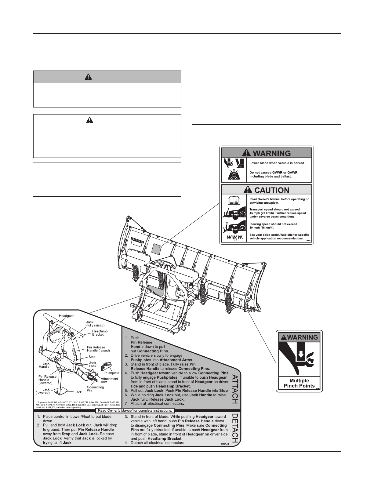
WARNING/CAUTION & INSTRUCTION
LABELS
Become familiar with and inform users about the
warning labels on the back of the blade and the
instruction label on the headgear.
NOTE: If labels are missing or cannot be read, see
your sales outlet.
Warning/Caution Label
Instruction Label
Multiple Pinch Points Label
(Both ends of blade)
Lit. No. 85501, Rev. 02 2 January 15, 2019
74800, 74810, 74850, 79810, 79850, 87800
SAFETY PRECAUTIONS
Improper installation and operation could cause
personal injury and/or equipment and property damage.
Read and understand labels and the Owner's Manual
before installing, operating, or making adjustments.
WARNING
Lower the blade when the vehicle is parked.
Temperature changes could change
hydraulic pressure, causing the blade to
drop unexpectedly or damaging hydraulic
components. Failure to do this could result in
serious personal injury.
WARNING
The driver shall keep bystanders clear of the
blade when it is being raised, lowered, or
angled. Do not stand between the vehicle and
the blade or within 8 feet of a moving blade. A
moving or falling blade could cause personal
injury.
WARNING
Keep hands and feet clear of the blade and
A-frame when mounting or removing the
snowplow. Moving or falling assemblies could
cause personal injury.
WARNING
Do not exceed GVWR or GAWR including
blade and ballast. The rating label is found on
driver-side vehicle door cornerpost.
WARNING
To prevent accidental movement of the blade,
always turn the control OFF whenever the
snowplow is not in use. The power indicator
light will turn OFF.
WARNING
Remove blade assembly before placing
vehicle on hoist.
CAUTION
Refer to the current eMatch selection system
for minimum vehicle recommendations and
ballast requirements.
HYDRAULIC SAFETY
WARNING
Hydraulic fl uid under pressure can cause skin
injection injury. If you are injured by hydraulic
fl uid, get medical attention immediately.
• Always inspect hydraulic components and hoses
before using. Replace any damaged or worn parts
immediately.
• If you suspect a hose leak, DO NOT use your
hand to locate it. Use a piece of cardboard or
wood.
FUSES
The FISHER® electrical and hydraulic systems
contain several automotive-style fuses. If a problem
should occur and fuse replacement is necessary,
the replacement fuse must be of the same type and
amperage rating as the original. Installing a fuse with
a higher rating can damage the system and could start
a fi re. Fuse Replacement, including fuse ratings and
locations, is located in the Maintenance section of the
Owner's Manual.
PERSONAL SAFETY
• Remove the ignition key and put the vehicle in
PARK or in gear to prevent others from starting
the vehicle during installation or service.
• Wear only snug-fi tting clothing while working on
your vehicle or snowplow.
• Do not wear jewelry or a necktie, and secure long
hair.
• Wear safety goggles to protect your eyes from
battery acid, gasoline, dirt, and dust.
• Avoid touching hot surfaces such as the engine,
CAUTION
Assembling a hose to the incorrect wing ram
port can result in permanent damage to the ram.
Lit. No. 85501, Rev. 02 3 January 15, 2019
radiator, hoses, and exhaust pipes.
• Always have a fi re extinguisher rated BC handy,
for fl ammable liquids and electrical fi res.
74800, 74810, 74850, 79810, 79850, 87800
1/4-20 109 154
1/4-28 121 171
5/16-18 150 212
5/16-24 170 240
3/8-16 269 376
3/8-24
297 420
7/16 -14
429 60 6
7/16 -20
9/16-12
9/16-18
5/8-11
5/8-18
3/4-10
3/4-16
7/8 - 9
7/8 -14 474 66 9
644 9091-8
1-12 704 995
1/2-13
1/2-20
11. 9
13.7
24.6
27.3
43.6
26.9
53.3
93
148
49.4
69.8
77.9
106.4
120. 0
8.4
9.7
17.4
19.2
30.8
35.0
49.4
55.2
75.3
85.0
M6 x 1.00
M12 x 1.75
M8 x 1.25
M14 x 2.00
M10 x 1.50
M27 x 3.00
M22 x 2.50
M30 x 3.50
M24 x 3.00
M20 x 2.5011.1
19.5
38.5
67
107
7.7
613
778
113 9
1545
450
428
562
796
1117
M33 x 3.50
M36 x 4.00
2101
2701
1468
1952
325
M16 x 2.00
231
167
M18 x 2.50 318222
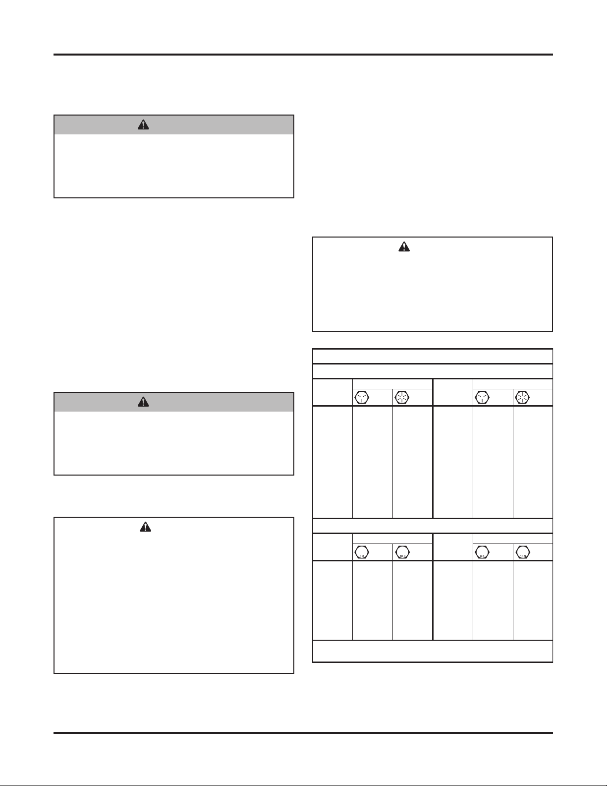
Recommended Fastener Torque Chart
Size Size
Tor q u e (ft-lb)
Grade
5
Grade
8
Metric Fasteners Class 8.8 and 10.9
These torque values apply to fasteners
except those noted in the instructions.
Tor q u e (ft-lb)
Grade
5
Grade
8
Size Size
Tor q u e (ft-lb)
Class
8.8
Class
10.9
Tor q u e (ft-lb)
Class
8.8
Class
10.9
Inch Fasteners Grade 5 and Grade 8
FIRE AND EXPLOSION
WARNING
Gasoline is highly fl ammable and gasoline
vapor is explosive. Never smoke while
working on vehicle. Keep all open fl ames
away from gasoline tank and lines. Wipe up
any spilled gasoline immediately.
Be careful when using gasoline. Do not use gasoline
to clean parts. Store only in approved containers away
from sources of heat or fl ame.
CELL PHONES
A driver's fi rst responsibility is the safe operation of
the vehicle. The most important thing you can do
to prevent a crash is to avoid distractions and pay
attention to the road. Wait until it is safe to operate
Mobile Communication Equipment such as cell phones,
text messaging devices, pagers, or two-way radios.
VENTILATION
NOISE
Airborne noise emission during use is below 70 dB(A)
for the snowplow operator.
VIBRATION
Operating snowplow vibration does not exceed 2.5 m/s2
to the hand-arm or 0.5 m/s2 to the whole body.
TORQUE CHART
CAUTION
Read instructions before assembling.
Fasteners should be fi nger tight until
instructed to tighten according to the torque
chart. Use standard methods and practices
when attaching snowplow, including proper
personal protective safety equipment.
WARNING
Vehicle exhaust contains lethal fumes.
Breathing these fumes, even in low
concentrations, can cause death. Never
operate a vehicle in an enclosed area without
venting exhaust to the outside.
BATTERY SAFETY
Batteries normally produce explosive gases,
which can cause personal injury. Therefore,
do not allow fl ames, sparks, or lit tobacco
to come near the battery. When charging or
working near a battery, always cover your
face and protect your eyes, and also provide
ventilation.
• Batteries contain sulfuric acid, which burns
• Disconnect the battery before removing or
Lit. No. 85501, Rev. 02 4 January 15, 2019
skin, eyes, and clothing.
replacing any electrical components.
CAUTION
74800, 74810, 74850, 79810, 79850, 87800
HEADGEAR TO A-FRAME ASSEMBLY
NOTE: For easier assembly and installation,
vehicle and all snowplow components should
be on a smooth, level, hard surface, such as
concrete.
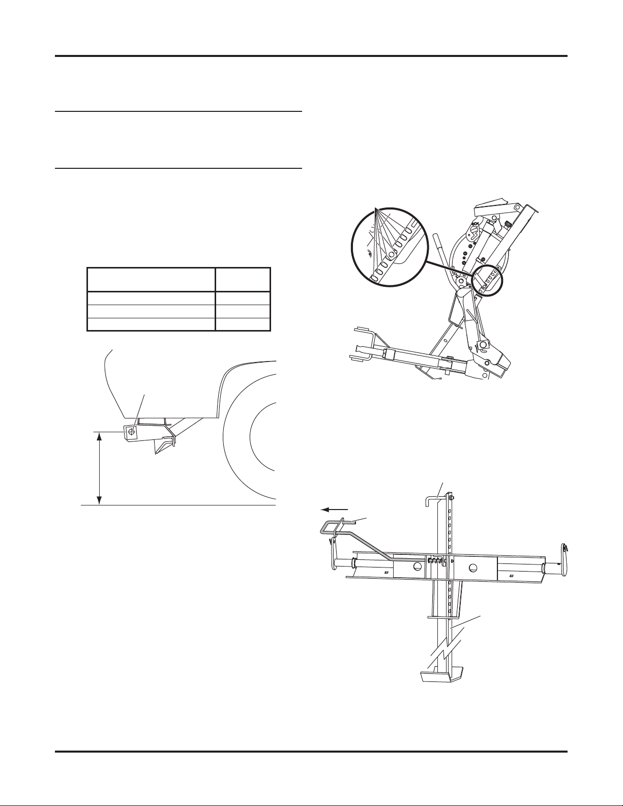
1. With the vehicle parked on a solid level surface,
measure the distance from the center of the
connecting pin hole to the ground. Using this
measurement, refer to the hole selection chart
below to determine which hole should be used to
attach the headgear to the A-frame.
Pushplate Height
(hole center to ground)
17" to 19" Top
15" to 17" (typical) Middle
13" to 15" Bottom
Center of
Connecting
Pin Hole
Measure
this distance.
Rear
Hole
6. Adjust the lift chain so there are an equal number
of links on each side of the lift arm. Then, while
supporting the headgear, remove and retain the
four pins and discard the shipping brackets.
7. Lower the jack leg in the headgear assembly so
that eight complete slots are showing through the
top of the headgear cross bar.
8 Slots
8. Release the jack lock to hold the jack in place.
Place the headgear assembly on top of the
A-frame assembly so that the headgear is tipped
backward and the jack leg is in between the
A-frame and push assembly.
Jack Handle
Jack Lock
2. If the vehicle is unavailable, use the middle holes
and reposition the headgear later, if necessary.
3. Set aside the parts bags, pivot bolt, and blade
guides. The vehicle electrical harnesses and
Owner's Manual packet are in the bag with the
headlamps box.
4. Remove the hardware and board(s) securing the
A-frame to the pallet.
5. Remove the hardware and bracket securing the
headgear to the A-frame.
Lit. No. 85501, Rev. 02 5 January 15, 2019
Jack
 Loading...