

Page 1

Product Bulletin
V270 Valve
D104178X012
Fisher™ V270 Full-Bore Ball Control Valve
The Fisher V270 is a three piece, trunnion mounted,
full-bore control valve designed from the ground up
with features for optimized pressure, flow and process
control.
The V270 full-bore ball valve is designed for
automated control in bypass, batch, monitor, and
emergency shutoff service applications, and it
presents little or no restriction to flow.
The V270 full-bore ball valve is available with
composition seals, and process type live-loaded shaft
packing for improved service life and lower emissions.
Unless otherwise noted, all NACE references are to
NACE MR0175/ ISO 15156.
51.3:V270
March 2021
Features
n Excellent Flow Control—Shaft and trunnion guiding
provides improved dynamic control.
n Sour Service and Sour Crude Oil Capability—
Standard construction materials comply with NACE
Standard MR0175 / ISO 15156.
n Tight Shutoff—Self-adjusting seals that are pressure
assisted provide Class VI shutoff for long reliable
service. The design incorporates a heavy duty
S31600 stainless steel carrier that retains the
composition seal.
n Free Standing Design—Comes standard with a base
bracket allowing the valve to sit upright.
X1454
FISHER V270 VALVE
n Heavy Duty Trunnions—The ball trunnions are
designed for demanding applications requiring long
service life, with a reduction in maintenance time
and costs.
n Double Block and Bleed—Design comes standard
with a dual seal arrangement.
n Optional Fire-Tested Construction—Certified for API
607 and 6FA.
www.Fisher.com
Page 2
Product Bulletin
51.3:V270
March 2021
Specifications
V270 Valve
D104178X012
Valve Body Sizes and End Connection Styles
NPS J 6, J 8, J 10, J 12, J 14, J 16, J 20, and
J 24 flanged valves with CL150, CL300, or CL600
raised-face flanges compatible with ASME
B16.5-2013
Designed in accordance with API 6D
Maximum Inlet Pressures and Temperatures
(1)
Consistent with CL150, CL300, or CL600
pressure-temperature ratings per ASME B16.34-2013
Allowable Temperature Range: -40 to 82_C
(-40 to 180_F)
Flow Characteristic
Modified equal percentage
Flow and Shutoff Direction
Dual Seal Construction: The V270 may be used for
unidirectional or bidirectional flow
Flow Coefficients
See Fisher Catalog 12
Shutoff Classification
ANSI/FCI 70-2 Class VI
Seal Material
Standard: POM (Polyoxymethylene)
Maximum Ball Rotation
90_
Packing Arrangements
Standard: Live-Loaded Packing
This packing system provides improved sealing,
guiding, and transmission of loading force to control
liquid and gas emissions
Dimensions
See figure 2 through 7
1. The pressure/temperature limits in this bulletin and any applicable standard or code limitation for this valve should not be exceeded.
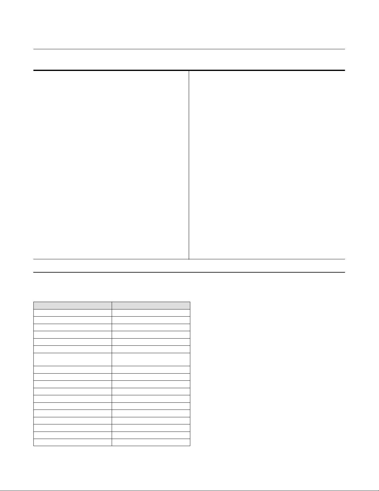
Table 1. Standard Materials of Construction
Part Material
Valve Body LF2 Carbon Steel
Ball LF2 Carbon Steel / ENP
Seal POM with S31600 SST Seal Carrier
Drive Shaft S17400 H1150D
Spring N07750
Tailpiece LF2 Carbon Steel
Tailpiece Mounting and
Packing Box Bolting
Bearing Plate LF2 Carbon Steel
Trunnion Bushings
Thrust Washer Glass filled PTFE
Shaft Bushing N04400 / Comp
Packing Box Housing Carbon Steel
Packing Live-Loaded PTFE
Packing Bolting B7M Steel
Packing Follower, Packing Box Ring S31600 SST
Straight Pins S17400 H1150D
O-Rings, Backup Rings Nitrile
Actuator Mounting Bolting Steel Grade 5
L7M Steel
Carbon Steel, Bronze, PTFE
2
Page 3
V270 Valve
D104178X012
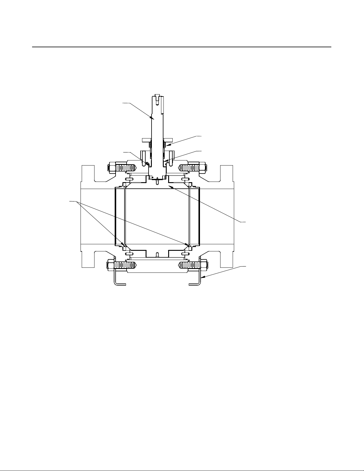
Figure 1. Sectional View of V270 Valve
SHAFT
Product Bulletin
51.3:V270
March 2021
LIVE LOADED PTFE PACKING
DUAL SEAL
ARRANGEMENT
THRUST BEARING
E1652
SHAFT BEARING
BALL
BASE BRACKET
3
Page 4

Product Bulletin
51.3:V270
March 2021
V270 Valve
D104178X012
Figure 2. Envelope Dimensions (see table 2)
A
U
W
E1653
Figure 4. NPS 24 CL600 Packing Box Housing
Mounting Pad Dimensions (see table 2)
U1
U2
T
R
E1656
W
T
Figure 3. Envelope Dimensions (see table 2 and 3)
G
N
Z
D
J
E1654
N
S
K
Figure 5. Shaft Detail (see table 3)
C
B
H
E1655
SECTION N-N
4
Page 5

V270 Valve
D104178X012
Product Bulletin
51.3:V270
March 2021
Figure 6. NPS 6 CL600 thru NPS 14 CL300 Base
Bracket Dimensions (see table 3)
E1
E1657
L
F1
Figure 7. NPS 14 CL600 thru NPS 24 CL600 Base
Bracket Dimensions (see table 3)
E1
E2
E1658
L
F2
F1
Figure 8. Live-Loaded Packing Arrangement Details
E1659
5
Page 6

Product Bulletin
51.3:V270
March 2021
Table 2. Envelope Dimensions
VALVE SIZE,
NPS
6
8
10
12
14
16
20
24
6
8
10
12
14
16
20
24
PRESSURE
CLASS
150 394 210.2 388.2 330
300 403 216.4 387.9 343 190
600 559 220.4 470.5 351 280
150 457 259.4 521.1 424 305
300 502 259.4 526.1 426 350
600 660 265.7 565.6 440 465
150 533 295.3 616.3 482
300 568 301.3 622.3 492 495
600 787 313.8 645.4 525 745
150 610 338.8 704.5 569 645
300 648 345.8 716.6 587 770
600 838 359.5 736.0 615 1050
150 686 369.0 821.0 628
300 762 401.8 827.2 630 1065
600 889 419.0 866.8 673 1365
150 762 435.2 936.9 701 1275
300 838 440.7 878.9 713 1455
600 991 464.5 923.1 762 1925
150 914 522.9 1074.9 875
300 991 530.0 1110.2 895
600 1194 555.5 1129.2 947 3450
150 1067 600.0 1287.9 1029
300 1143 615.0 1312.2 1066 88.8 4280
600 1397 649.0 1280.4 1140 101.6 609.6
150 15.50 8.27 15.28 12.99
300 15.88 8.52 15.27 13.50 415
600 22.00 8.68 18.52 13.82 620
150 18.00 10.21 20.52 16.70 670
300 19.75 10.21 20.71 16.77 775
600 26.00 10.46 22.27 17.32 1020
150 21.00 11.62 24.26 18.98
300 22.38 11.86 24.50 19.37 1095
600 31.00 12.35 25.41 20.67 1640
150 24.00 13.34 27.74 22.40 1425
300 25.50 13.61 28.21 23.11 1695
600 33.00 14.15 28.97 24.21 2320
150 27.00 15.59 32.32 24.70
300 30.00 15.82 32.57 24.80 2350
600 35.00 16.50 34.13 26.50 3015
150 30.00 17.13 36.89 27.61 2810
300 33.00 17.35 34.60 28.05 3210
600 39.00 18.29 36.34 29.98 4250
150 36.00 20.59 42.32 34.45
300 39.00 20.87 43.71 35.24
600 47.00 21.87 44.46 37.28 7610
150 42.00 23.62 50.71 40.51
300 45.00 24.21 51.66 41.97 3 1/2 9435
600 55.00 25.55 50.41 44.88 4 24.00
A K H R∅
V270 Valve
D104178X012
S∅ G∅
Shaft
Dia.
Keyway
Dia.
T U
mm kg
44.4 41.3 237.1 50.8
63.5 57.1 336.6 76.2
76.2
88.9
101.6
69.8
533.4 127.0
82.5
69.8 3380
475.2 (U1)
254.0 (U2)
Inches Pounds
1 3/4 1 5/8 10.75 2.00 3/4-10
2 1/2 2 1/4 13.25 3.00 7/8-9
3
3 1/2
4
2 3/4
21.00 5.00
3 1/4
2 3/4 7450
18.00 (U1)
10.00 (U2)
W
(THREADED)
See Below
1-1/4-8
APPROXIMATE
WEIGHT
170
430
1045
2245
2580
5775
370
950
2305
4945
5685
12740
6
Page 7

V270 Valve
D104178X012
Table 3. Additional Envelope Dimensions
VALVE SIZE,
NPS
6
8
10
12
14
16
20
24
6
8
10
12
14
16
20
24
PRESSURE
CLASS
150
300
600 242.4 200.1
150 250.4 273.1
300 269.4 231.4
600 302.4 292.1
150
300 282.4 251.8
600 328.9 307.6
150 318.0 279.9
300 328.2 330.2
600 389.4 330.2
150
300 428.5 396.8
600 644.0 415.4 453.3 224.7
150 706.1 439.4 489.3 222.6
300 678.0 487.5 502.5 312.0
600 677.1 486.6 568.2 352.3
150 823.2 556.5 598.7 338.3
300
600 871.2 604.5 708.4 441.7
150 394.0 408.3 282.7 82.8 15.9 944.6 627.1 634.6 317.1
300 381.0 409.0 260.6 98.3 22.2 1001.3 658.4 657.3 314.4
600 363.0 379.0 N/A 112.5 25.4 1009.5 704.7 853.4 548.6
150
300
600 9.54 7.88
150 9.86 10.75
300 10.61 9.11
600 11.91 11.50
150
300 11.12 9.92
600 12.95 12.11
150 12.52 11.02
300 12.92 13.00
600 15.33 13.00
150
300 16.87 15.62
600 25.35 16.35 17.85 8.85
150 27.80 17.30 19.26 8.76
300 26.69 19.19 19.78 12.28
600 26.66 19.16 22.37 13.87
150 32.41 21.91 23.57 13.32
300
600 34.30 23.80 27.89 17.39
150 15.51 16.07 11.13 3.26 0.63 37.19 24.69 24.99 12.49
300 15.00 16.10 10.26 3.87 0.88 39.42 25.92 25.88 12.38
600 14.29 14.92 N/A 4.43 1.00 39.74 27.74 33.60 21.60
D Z J
228.6 239.8 149.1 45.3 9.5
297.0 309.4 201.7 62.6 12.7
394.0 408.3 279.7 76.7 15.9
381.0 409.0 260.6 90.7 19.1
9.00 9.44 5.87 1.78 0.38
11.69 12.18 7.94 2.46 0.50
15.51 16.07 11.01 3.02 0.63
15.00 16.10 10.26 3.57 0.75
C B
Shaft &
Key
Height
mm
Inches
Key
Width
Product Bulletin
51.3:V270
March 2021
E1 E2 F1 F2 L
N/A
278.1 297.0
422.5 482.5
813.5 559.5 618.9 364.9
N/A
10.95 11.69
16.63 19.00
32.03 22.03 24.37 14.37
N/A
N/A
N/A
N/A
N/A
N/A
N/A
15.9
19.1
N/A
0.63
0.75
7
Page 8

Product Bulletin
51.3:V270
March 2021
Figure 9. Dead Angle (also see table 4)
V270 Valve
D104178X012
VIEW A
VIEW A
SCALE 1:2
THE AMOUNT THE BALL ROTATES FROM CLOSED,
AT WHICH, CONTROLLABLE FLOW BEGINS
GH08473
Table 4. Dead Angle Degrees
VALVE SIZE, NPS DEAD ANGLE, DEGREES
6 12
8 11
10 8
12 9
14 8
16 7
20 7
24 7
Neither Emerson, Emerson Automation Solutions, nor any of their affiliated entities assumes responsibility for the selection, use or maintenance
of any product. Responsibility for proper selection, use, and maintenance of any product remains solely with the purchaser and end user.
Fisher is a mark owned by one of the companies in the Emerson Automation Solutions business unit of Emerson Electric Co. Emerson Automation Solutions,
Emerson, and the Emerson logo are trademarks and service marks of Emerson Electric Co. All other marks are the property of their respective owners.
The contents of this publication are presented for informational purposes only, and while every effort has been made to ensure their accuracy, they are not
to be construed as warranties or guarantees, express or implied, regarding the products or services described herein or their use or applicability. All sales are
governed by our terms and conditions, which are available upon request. We reserve the right to modify or improve the designs or specifications of such
products at any time without notice.
Emerson Automation Solutions
Marshalltown, Iowa 50158 USA
Sorocaba, 18087 Brazil
Cernay, 68700 France
Dubai, United Arab Emirates
Singapore 128461 Singapore
www.Fisher.com
E 2017, 2021 Fisher Controls International LLC. All rights reserved.
8
 Loading...