

Page 1
Instruction Manual
D102178X012
Fisher™ V260 Rotary Pipeline Ball Valve
V260 Valve
July 2017
Contents
Introduction 1.................................
Scope of Manual 1.............................
Description 1.................................
Specifications 2...............................
Educational Services 2.........................
Installation 3..................................
Maintenance 4.................................
Packing Maintenance 5.........................
Stopping Leakage 5........................
Replacing Packing 6........................
Seal Ring Maintenance
Disassembly 7.............................
Assembly 9...............................
Actuator Mounting 12...........................
Determining Mounting Position 12...............
Determining Closed Position 12.................
Parts Ordering 12...............................
Parts List 14...................................
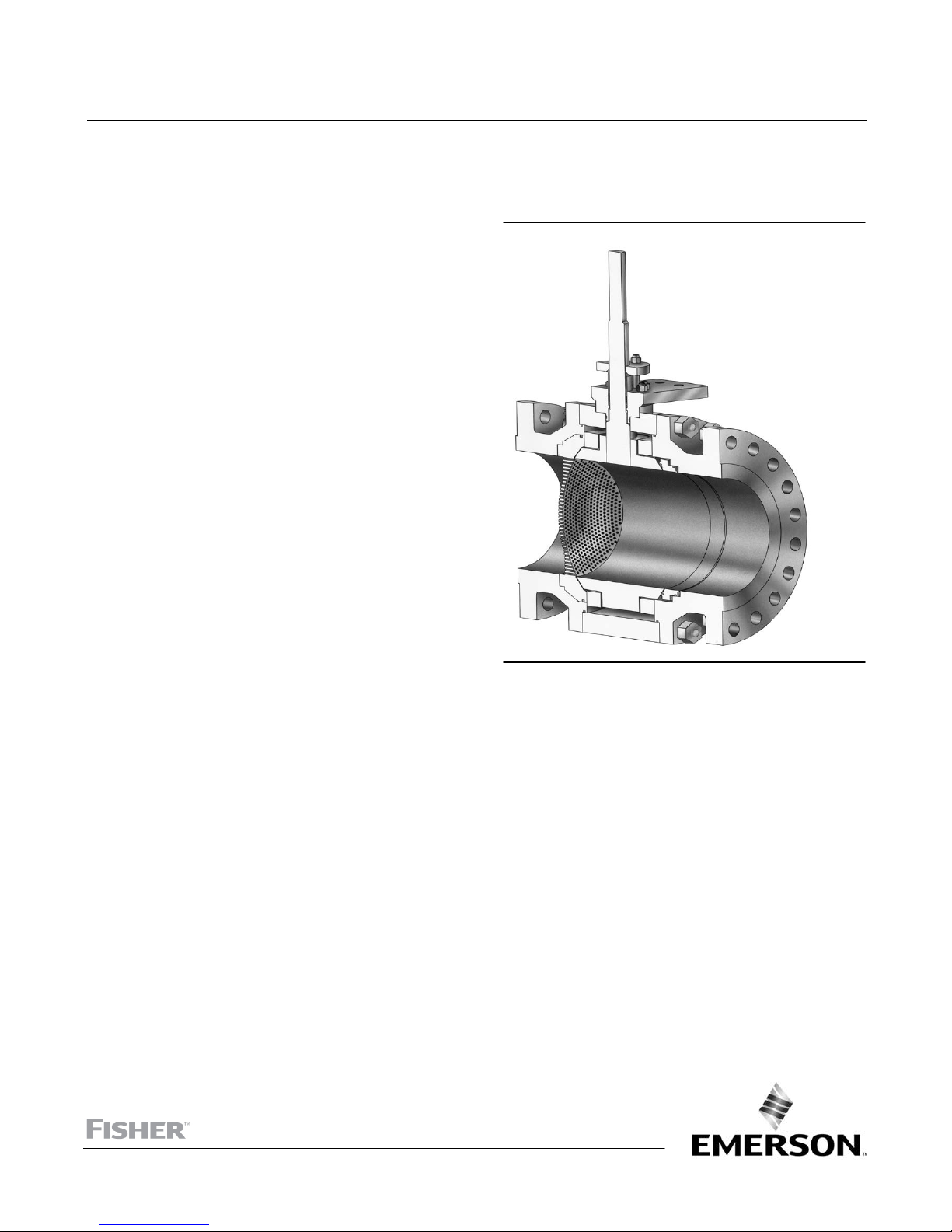
Figure 1. Fisher V260 Sectional View
W6365‐2
Introduction
Scope of Manual
This instruction manual provides installation, operation, maintenance, and parts information for the Fisher V260
control valve. Refer to separate manuals for information concerning the actuator, positioner, and accessories (see
figure 1).
Do not install, operate, or maintain a V260 valve without being fully trained and qualified in valve, actuator, and
accessory installation, operation, and maintenance. To avoid personal injury or property damage, it is important to
carefully read, understand, and follow all the contents of this manual, including all safety cautions and warnings. If you
have any questions about these instructions, contact your Emerson sales office
proceeding.
Description
V260 throttling ball valves are available in single‐seal, double block‐and‐bleed, dual‐seal, and bidirectional flow
constructions with or without attenuators. Valves with dome‐style attenuators combine the efficiency of a rotary valve
with the noise reducing capability of a special trim (figure 4). Valves without attenuators present little or no restriction
to flow at full travel.
or Local Business Partner before
www.Fisher.com
Page 2

V260 Valve
July 2017
Table 1. Specifications
Instruction Manual
D102178X012
Valve Body Size and End Connection Styles
(1)
NPS 8, 10, 12, 16, 20, and 24 flanged valves with
CL150, CL300, and CL600 raised‐face or ring‐type
joint flanges compatible with ASME B16.5. See table 2
for face‐to‐face dimensions. Consult factory for other
pressure ratings.
Maximum Inlet Pressures and Temperatures
(1)
Consistent with CL150, CL300, and CL600
pressure‐temperature ratings per ASME B16.34
Maximum Allowable Shutoff Pressure Drop
(1)
For Single‐Seal and Dual‐Seal Construction:
(Except where further limited by the
pressure‐temperature rating of valve body material)
For LF2 valve body material:
CL150: 19.6 bar (285 psi) at 38_C (100_F)
CL300: 51 bar (740 psi) at 38_C (100_F)
CL600: 103 bar (1480 psi) at 38_C (100_F)
Seal Material and Temperature Capability
J POM
J PTFE/PEEK
(2)
(Standard) -29 to 82_C (-20 to 180_F)
(2)(3)
(Optional) -29 to 93_C (-20 to
(1)
200_F)
Flow and Shutoff Direction
Unidirectional flow for Fisher V260 is forward flow.
Seal is upstream.
J Single Seal Constructions: Should be used for
unidirectional flow and unidirectional shutoff only.
J Dual Seal Constructions: V260A and V260C may be
used for unidirectional or bidirectional flow. V260B
should be used for unidirectional flow only for most
effective anti‐cavitation protection. Bidirectional
shutoff requires the dual seal construction.
Shutoff Classification
Single‐Seal Composition Constructions: 0.001% of
maximum valve capacity (ANSI/FCI 70-2 Class IV and
IEC 60534-4)
Dual‐Seal Composition Constructions: 0.001% of
maximum valve capacity (ANSI/FCI 70-2 Class IV and
IEC 60534-4)
Maximum Ball Rotation
90 degrees
Actuator Mounting
Right‐hand or left‐hand mounted as viewed from the
valve inlet for forward flow
Flow Characteristic
Modified equal percentage
1. The pressure‐temperature limits in this instruction manual and any applicable standard or code limitation for valve should not be exceeded.
2. POM stands for polyoxymethylene, PTFE stands for polytetrafluorethylene, and PEEK stands for poly-ether-ether-ketone.
3. Temperature limits of PTFE/PEEK is limited due to standard nitrile O‐ring. Contact your Emerson sales office
Approximate Weight
See table 2
or Local Business Partner for higher temperature options, up to 232_C (450_F).
Educational Services
For information on available courses for Fisher V260 valves, as well as a variety of other products, contact:
Emerson Automation Solutions
Educational Services - Registration
Phone: 1-641-754-3771 or 1-800-338-8158
E-mail: education@emerson.com
emerson.com/fishervalvetraining
2
Page 3
Instruction Manual
D102178X012
V260 Valve
July 2017
Installation
WARNING
D To avoid personal injury, always wear protective gloves, clothing, and eyewear when performing any installation
operations.
D To avoid personal injury or property damage resulting from the bursting of pressure retaining parts, be certain the
service conditions do not exceed the limits given in this manual.
D To avoid personal injury or property damage that can result from the sudden release of process pressure if valve or
mating pipe flange pressure ratings are exceeded, provide a relief valve for over‐pressure protection as required by
government or accepted industry codes and good engineering practices.
D Service conditions are limited for valve and trim material combinations. Do not apply any other service condition to the
valve without first contacting your Emerson sales office
D Personal injury could result from packing leakage. The valve packing was tightened before shipment however, the
packing might require some readjustment to meet specific service conditions.
D Check with your process or safety engineer for any additional measures that must be taken to protect against process
media.
D If installing into an existing application, also refer to the WARNING at the beginning of the Maintenance section in this
instruction manual.
D To avoid personal injury or property damage, a minimum of two swivel hoists must be used when lifting NPS 24 CL600
assemblies.
or Local Business Partner.
Table 2. Face‐to‐Face Dimensions and Approximate Weights
VALVE SIZE, NPS
1. For CL150 and CL300 valves, face‐to‐face dimensions are the same as CL600 valves.
(1)
(CL600
)
8 661 424
10 788 653
12 840 882
16 990.6 2472
20 1144 4313
24 1397 7257
8 26.04 975
10 31.04 1550
12 33.07 2025
16 39.0 5450
20 47.0 9500
24 55.0 16000
FACE‐TO‐FACE
DIMENSIONS
mm kg
Inches Pounds
APPROXIMATE WEIGHT
Key number locations are shown in figure 6, unless otherwise noted.
1. Install a three‐valve bypass around the control valve assembly if continuous operation will be necessary during
inspection and maintenance of the valve.
2. The valve is normally shipped as part of a control valve assembly, with an actuator mounted on the valve. The
valve/actuator assembly is adjusted at the factory before the unit is shipped.
If the valve or actuator has been purchased separately or if the actuator has been removed, mount the actuator
according to the Actuator Mounting section and the appropriate actuator instruction manual. Make any necessary
adjustments on the bench before installing the valve in the pipeline. With the valve in the pipeline, you cannot see the
exact position of the ball to determine the fully open or closed positions.
3
Page 4
V260 Valve
July 2017
Instruction Manual
D102178X012
3. Standard flow direction is shown in figure 6. If possible, install the valve in a horizontal pipeline with the drive shaft
horizontal. The actuator can be right‐ or left‐hand mounted in any of the positions shown in the actuator instruction
manual. If necessary, refer to the appropriate actuator instruction manual for installation and adjustment
procedures.
4. Be certain the valve and adjacent pipelines are free of any foreign material that could damage the valve sealing
surfaces. Impurities or entrained solids in the process fluid could plug the passages in the trim. If the process fluid is
not clean, install a filter upstream to keep the pipeline free of impurities or entrained solids.
5. Provide appropriate flange gaskets, and place the valve in the pipeline. Tighten flange bolting in a criss‐cross
sequence to ensure the flange gaskets are loaded evenly.
Note
Standard Fisher V260 valve packings (key 105) are composed of:
D
Conductive packing ring (graphite ribbon packing), or
Partially conductive packing rings (For example: a carbon‐filled PTFE female adaptor with PTFE V‐ring packing or a
D
graphite‐composition packing ring with PTFE/composition packing ring)
In order to electrically bond the drive shaft to the valve body for hazardous area service, an alternate shaft‐to‐body bonding strap
can be provided by using the following step.
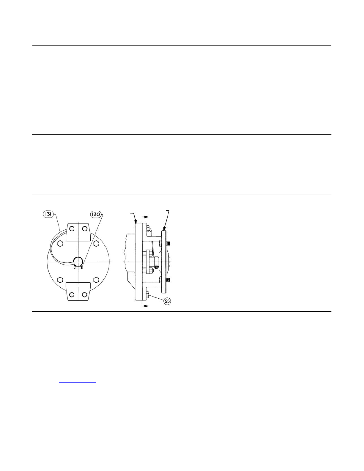
Figure 2. Optional Shaft‐to‐Body Bonding Strap Assembly
VALVE BODY
ACTUATOR
A
37A6528-A
A3143-2
VIEW A-A
6. For hazardous applications, attach the optional bonding strap assembly (key 131) to the valve drive shaft (key 6)
with the clamp (key 130) and connect the other end of the bonding strap assembly to the valve body with the
mounting cap screw as shown in figure 2.
7. Connect pressure lines to the actuator as indicated in the actuator instruction manual. When an auxiliary manual
actuator is used with a power actuator, install a bypass valve on the power actuator (if one is not supplied) for use
during manual operation.
8. If the valve has ENVIRO‐SEAL™ live‐loaded packing installed, an initial re‐adjustment may not be required,
depending on your application. See the Fisher instruction manual titled ENVIRO‐SEAL Packing System for Rotary
Valves (D101643X012
) for packing instructions and adjustments (see figure 3).
Maintenance
Valve parts are subject to normal wear and must be inspected and replaced as necessary. The frequency of inspection
and replacement depends upon the severity of service conditions.
4
A
Page 5
Instruction Manual
D102178X012
V260 Valve
July 2017
Key numbers are shown in figure 6, unless otherwise noted.
WARNING
Avoid personal injury or equipment damage from sudden release of process pressure or uncontrolled movement of parts.
Before performing any maintenance operations:
D Do not remove the actuator from the valve while the valve is still pressurized.
D Always wear protective gloves, clothing, and eyewear when performing any maintenance operations to avoid personal
injury.
D Disconnect any operating lines providing air pressure, electric power, or a control signal to the actuator. Be sure the
actuator cannot suddenly open or close the valve.
D Vent the power actuator loading pressure and relieve any actuator spring precompression.
D Use bypass valves or completely shut off the process to isolate the valve from process pressure. Relieve process pressure
from both sides of the valve. Drain the process media from both sides of the valve.
D Dual‐seal valve constructions can retain pressure and process fluid even after process pressure has been removed from
both sides of the valve. Relieve this pressure before disassembling or removing the valve from the line. Take additional
care if the process fluid is hot, flammable, caustic, or hazardous.
D Carefully secure the valve in an upright position. The roundness of the flanges and valve body allow it to easily roll from
side‐to‐side. The combined weight of the valve/actuator assembly could cause injury or property damage when falling
to the side.
D Use lock‐out procedures to be sure that the above measures stay in effect while you work on the equipment.
D The valve packing box may contain process fluids that are pressurized, even when the valve has been removed from the
pipeline. Process fluids may spray out under pressure when removing the packing hardware or packing rings, or when
loosening the packing box pipe plug.
D Avoid injury by keeping hands, tools, and other objects away from the ball while stroking the valve.
D Check with your process or safety engineer for any additional measures that must be taken to protect against process
media.
D To avoid personal injury or property damage, a minimum of two swivel hoists must be used when lifting NPS 24 CL600
assemblies.
Packing Maintenance
Note
For the ENVIRO‐SEAL Packing System, refer to the separate ENVIRO‐SEAL Packing System for Rotary Valves instruction manual,
D101643X012
Stopping Leakage
For standard PTFE V‐ring packing, leakage around the packing follower may be stopped by tightening the packing
follower nuts.
If the packing is relatively new and tight on the drive shaft, and if tightening the packing follower nuts does not stop
the leakage, the drive shaft may be worn or nicked so that a seal cannot be made. If the leakage comes from the
outside diameter of the packing, the leakage may be caused by nicks or scratches on the packing box wall. Inspect the
drive shaft and packing box wall for nicks or scratches while performing the following procedure.
, for maintenance instructions.
5
Page 6

V260 Valve
July 2017
Instruction Manual
D102178X012
Replacing Packing
Replacing the packing requires bleeding off the system and removing the actuator from the valve. Valve/actuator
adjustments cannot be made correctly without observing the fully open or closed position of the ball (key 11). It is not
necessary to remove the valve from the pipeline, if care is taken to note the position and alignment of the lever and
shaft and to not disturb the turnbuckle position.
Figure 3. Packing Arrangement Details
DRIVE SHAFT
(KEY 20)
PACKING FLANGE
(KEY 102)
PACKING
FOLLOWER
(KEY 114)
TYPICAL PTFE
V-RING PACKING
SET (KEY 105)
PACKING BOX
RING (KEY 107)
PACKING STUD
AND NUT
(KEYS 100 AND 101)
TYPICAL
ENVIRO-SEAL
PTFE V-RING
PACKING SET
94BA02200-D
B2472-1
STANDARD
PACKING ARRANGEMENT
ENVIRO-SEAL
PACKING ARRANGEMENT
Disassembly
1. Isolate the control valve from the line pressure, release pressure from both sides of the valve body, and drain the
process media from both sides of the valve. If using a power actuator, shut off all pressure lines (or other power
source) to the power actuator, release pressure from the actuator, and disconnect the pressure lines from the
actuator. Use lock‐out procedures to be sure that the above measures stay in effect while you work on the
equipment.
WARNING
See the WARNING at the beginning of the Maintenance section for more information before removing the valve from the
pipeline.
2. Remove line bolting, remove the control valve from the pipeline, and place the actuator/valve assembly on a flat
surface.
3. Remove the actuator cover. Note and mark the orientation of the actuator with respect to the valve body and the
lever orientation with respect to the valve drive shaft, to assist with reassembly.
4. Loosen the lever locking device cap screw. Loosening the lever turnbuckle adjustment is not necessary during
disassembly. When remounting the actuator, the turnbuckle will be used for actuator adjustments.
5. Removing the actuator from the valve:
6
Page 7

Instruction Manual
D102178X012
a. Remove the actuator mounting screws, bolts, or nuts.
V260 Valve
July 2017
CAUTION
When removing the actuator from the valve, do not use a hammer or similar tool to drive the lever or actuator off the valve
shaft. Driving the lever or actuator off the valve shaft could damage the ball, seal(s), and valve.
If necessary, use a wheel puller to remove the lever or actuator from the valve shaft. Tap the wheel puller screw lightly to
loosen the lever or actuator. Do not hit the screw with excessive force. Using excessive force could damage the ball, seal(s),
and valve.
b. Slide the lever along the valve shaft while removing the actuator from the valve.
6. If necessary, remove the bonding strap assembly, shown in figure 2, from the valve before attempting to remove
the packing box parts.
7. Remove the packing follower nuts, packing flange, and packing follower (keys 101, 102, and 114, figure 3).
8. Remove the packing parts:
a. If the packing housing (key 16) is mounted on the valve: Use a formed wire hook with a sharp end to pierce the
packing rings, and pull the rings out of the packing box. Do not scratch the drive shaft or packing box wall.
Scratching these surfaces could cause leakage. Clean, inspect, and obtain replacement parts as necessary for
reassembly.
b. If the packing housing is removed from the valve: Remove the drive shaft (key 20) from the packing housing.
With the drive shaft removed, remove all internal parts. Clean, inspect, and obtain replacement parts as
necessary for reassembly.
The packing sets (key 105) listed in the parts list do not include any metal parts. Either clean and reuse metal packing
parts or obtain replacements by ordering them individually.
Assembly
If the valve is equipped with the ENVIRO‐SEAL packing system, refer to the ENVIRO‐SEAL Packing System Rotary Valves
instruction manual (D101643X012
1. If the packing housing assembly (key16) is removed from the valve, use the valve assembly steps to reinstall the
drive shaft (key 20) and packing housing assembly on the valve.
2. For standard packing arrangements, install the new packing parts using the parts sequence shown in figure 3.
3. Secure the packing follower and packing flange with the packing nuts (keys 114, 102, and 101). Tighten the nuts far
enough to stop leakage during operating conditions.
4. If necessary, install the bonding strap assembly shown in figure 2.
5. Use the steps provided in the Actuator Mounting section to install the actuator on the valve. For actuator travel
adjustments, refer to the appropriate actuator instruction manual.
6. When the control valve is installed in the pipeline and in operation, check around the packing follower for leakage
and retighten the packing nuts as necessary.
) for assembly.
Seal Ring Maintenance
Disassembly
WARNING
For valves with dual‐seals, fluid and/or a hazardous material may be trapped under pressure in the valve body cavity. To
avoid personal injury, relieve the pressure, and drain any remaining fluid or hazardous material from the valve body cavity.
If necessary, disassemble the valve in a safe area for cleaning.
7
Page 8

V260 Valve
July 2017
See the WARNING at the beginning of the Maintenance section for more information before removing the valve from the
pipeline.
Instruction Manual
D102178X012
Disassemble the valve only to the extent necessary to accomplish the needed inspection and repairs. For some repairs
(for example, the trim parts only) complete disassembly of the valve is not necessary. Follow the disassembly
procedures to the point necessary to accomplish the repair, then skip to the appropriate assembly steps to complete
the reassembly of the valve. Always clean and protect sealing surfaces from damage.
Mark parts as necessary to allow them to be returned to the same position as removed. For example: Be sure to return
the tailpiece to the same end of the valve from which it was removed. Also, the seal assembly within the tailpiece
should be returned to the same tailpiece from which it was removed. The bearing plates should be marked and
reinstalled on the ball in the same position as they were, when removed.
1. Isolate the control valve from the line pressure, release pressure from both sides of the valve body, and drain the
process media from both sides of the valve. If using a power actuator, shut off all pressure lines to the power
actuator, release pressure from the actuator, and disconnect the pressure lines from the actuator. Use lock‐out
procedures to be sure that the above measures stay in effect while you work on the equipment.
2. Remove line bolting, remove the control valve from the pipeline, and clean all valve surfaces. Place the
actuator/valve assembly on a flat working surface.
3. Mark parts as necessary to allow them to be returned to the same position during re‐assembly.
4. Perform the procedure in the Packing Maintenance section to remove the actuator from the valve. When valve
maintenance is complete, refer to the Mounting Actuator procedure at the end of the Maintenance section to
re‐install the actuator on the valve.
5. Provide a clean soft working surface to protect the tailpiece‐flange sealing surface.
a. If the valve does not have an attenuator dome, lift the valve and place it on its side with either tailpiece flange
resting on the flat surface. Be sure the valve is in a stable, upright position before releasing the hoist connection.
b. If the valve has a single attenuator dome, it is best to position the valve body so the tailpiece with the dome is in
the down position. Be sure the valve is stable, in an upward position before releasing the hoist connection.
Note
If the packing is in good condition, it is possible to remove and replace the seal assembly, or dome assembly without removing the
packing box assembly. However, the packing assembly must be removed to remove the ball (key 11) from the valve body.
6. Remove the packing housing nuts (key 23). Remove the packing housing assembly from the valve. The assembly
includes all the packing box parts, drive shaft, O‐ring seals, bearing, and other parts.
7. Remove the nuts from the studs (keys 19 and 3) to remove the tailpiece/valve connection. (Refer to figure 6).
Note
While lifting the tailpiece (key 2 or 6) from the valve body, check to see if the seal assembly is lifting with the tailpiece. (Note:
Some valve constructions do not have a seal assembly installed in the tailpiece.) If it is, slide something between the ball and
tailpiece to protect the ball in case the seal assembly falls out of the tailpiece.
8. If the valve has dual attenuator domes, tap the dome to loosen it from the top tailpiece before the top tailpiece is
lifted from the valve body.
8
Page 9

Instruction Manual
D102178X012
V260 Valve
July 2017
9. Turn the tailpiece over so the seal assembly is facing up, and place it on a clean soft surface with the flange face
down.
10. From the tailpiece assembly or from the valve, remove the seal assembly, wave spring, and O‐ring seal (keys 8
and 7). Clean and protect all sealing surfaces.
WARNING
In the next step, be sure to secure the bearing plates on the ball to prevent them from falling. When lifting the ball, the
bearing plates may slide‐off the ball trunnions which may cause personal injury or property damage.
11. Turn the ball (key 11) to the closed position. Use a nylon sling through the ball bore to lift the ball out of the valve
body. Lift the ball and set it on a clean soft surface.
12. Remove the two bearing plates and thrust washers (key 4 and 30) from the ball (key 11). Inspect the bearing in the
bearing plates and thrust washers (keys 29 and 30). If necessary, remove and replace the bearings (key 29).
13. Evenly loosen the hex nuts from the studs on the lower tailpiece (key 2 or 6). Remove the valve body from the
tailpiece.
14. Remove from the tailpiece assembly, the dome assembly and/or the seal assembly, wave spring, and O‐ring seal.
Clean and protect all sealing surfaces.
Assembly
Be sure to replace valve parts in the same position that they were removed. Use the following suggested sequence to
reassemble the valve.
Note
Clean and protect all sealing surfaces from damage while installing parts. Lubricate parts when necessary as an aid for installing
parts, and to help protect sealing surfaces.
Key number locations are shown in figure 6.
1. Place the tailpiece (key 2 or 6), pipe flange end down on a clean soft surface with the seal assembly or attenuator
dome cavity facing up.
2. Lubricate and install the O‐rings (key 12) on both tailpieces.
For characterized domes, install the grooved end of the dome groove pin (key 33) into the tailpiece, as far as it will go.
Use only a light tapping force, taking care not to bend the pin. This groove pin will prevent the attenuator dome from
rotating with respect to the tailpiece.
3. Install the inlet end attenuator dome (key 28 or 10) into the tailpiece (key 6). Use the lifting lugs in the two
threaded holes for ease of handling.
For characterized attenuators, align the pin hole in the dome with the groove pin (key 33) placed in the tailpiece in
step 3. High Density attenuators don't require this orientation.
For dual seal V260A or V260B constructions, lubricate and install the O‐ring (key 15) on the dome spacer (key 13). If a
dual dome is being assembled, install the dome spacer into the tailpiece, using the two threaded holes as lifting lugs.
4. Apply thread locking adhesive to and install the two cap screws (key 36) that hold the washers (key 37) which help
retain the dome or dome spacer (if applicable) in the tailpiece.
For constructions with dual dome and/or dual seals, lubricate and install the O‐ring (key 7) in the groove on the inlet
seal (key 9). Install the wave spring (key 8) over the end of the seal. Install the seal assembly O‐ring (key 7) between the
dome spacer and the dome (key 10).
9
Page 10

V260 Valve
July 2017
Note
D
Verify that the ball opens into the dome windows last. (See figure 5)
D
If not, remove the dome and tailpiece and turn it 180 degrees to allow the windows to open last.
Instruction Manual
D102178X012
5. Install the grooved end of the groove pins (key 5) into the bearing plates (key 4) as far as they will go. Use only a
light tapping force, taking care not to bend the pins.
6. Apply dry film lubrication between the trunnion surfaces on the ball and the trunnion bearings.
7. Install new bearings (key 29) in the bearing plates (key 4).
WARNING
In the next step, be sure to secure the bearing plates on the ball to prevent them from falling. When lifting the ball, the
bearing plates may slide off the ball trunnions which may cause personal injury or property damage.
8. Lift the ball with a nylon sling through the bore and turn the ball until the port and trunnions are horizontal.
9. Slide one ball thrust washer (key 30) onto each side of the ball trunnions, and install a bearing plate (key 4) on each
side of the ball trunnions.
10. Carefully lower the ball and bearing plates onto the lower (inlet) tailpiece taking care not to damage the ball
surface.
While lowering the ball, guide the groove pins in the bearing plates into their proper location in the tailpiece. To
determine the proper location for Right Hand Mounting, turn the splined trunnion so that it is on your right hand side
when the attenuator dome is in front of you and the bottom of the valve is nearest you.
11. Install the grooved end of the groove pin (key 18) into the valve body, as far as it will go. Use only a light tapping
force, taking care not to bend the pin. Install the body studs (key 3) in the valve body and install two swivel hoists for
lifting the valve body.
12. Lift the valve body, using the swivel hoists, so it is centered over the ball and bearing plates. Be sure the shaft hole
is aligned with the splined trunnion on the ball. When lowering the valve body, take care not to damage the ball.
Guide the groove pins in the valve body into their proper location in the tailpiece.
13. Install the hex nuts(key 19) on the studs (key 3) and hand‐tighten them.
14. Lubricate and install the O‐ring (key 14) on the packing housing (key 16). Install the shaft bearing (key 32) in the
packing box housing.
15. Install the packing housing studs (key 22) in the valve body.
16. Apply anti‐seize lubricant to the large spline on the shaft. Line‐up the missing spIine tooth with the appropriate
space in the ball, and install the drive shaft (key 20) into the ball.
17. Install the shaft thrust washer (key 24) onto the shaft.
18. Install the packing housing (key 16) and nuts (key 23), and tighten them evenly. Orient the length of the packing
box housing perpendicular to the bore of the valve body.
WARNING
Refer to table 3 for bolt torque requirements. Exceeding any torque requirements could damage the valve and impair safe
operation.
10
Page 11

Instruction Manual
D102178X012
Table 3. Torque Values
VALVE SIZE, NPS
8
10
12
16
20
24
PRESSURE
RATING
CL150 393 290
CL300 549 405
CL600 746 550
CL150 549 405
CL300 746 550
CL600 990 730
CL150 549 405
CL300 990 730
CL600 990 730
CL150 746 550
CL300 1750 1290
CL600 1750 1290
CL150 990 730
CL300 2237 1650
CL600 3470 2560
CL150 1749 1290 990 730
CL300 3470 2560 990 730
CL600 6088 4490 1749 1290
VALVE BODY HEX NUT (KEY 19) MOUNTING FLANGE HEX NUT (KEY 23)
NSm lbf‐ft NSm lbf‐ft
271 200
746 550
990 730
V260 Valve
July 2017
19. Assemble the seal and install the second tailpiece using the following steps.
For dual seal and dual dome constructions, it is easier to lay the valve assembly on its side while installing the second
tailpiece.
20. Install the dome, dome spacer, and alignment groove pins (if a characterized attenuator is used) in the tailpiece.
21. Lubricate and install the seal assembly O‐ring (key 7) in the groove of the seal as shown in figure 6.
22. Install the wave spring (key 8) over the end of the seal (key 17 or 9). Note that the spring is not required with the
attenuator dome (key 28, figure 6).
23. For single seal constructions, place the seal ring assembly into the tailpiece, taking care not to damage the O‐ring
(key 7) while sliding it into the tailpiece. Also, be careful to protect all sealing surfaces.
For dual seal constructions, place the seal assembly (key 17) into the dome, dome spacer and tailpiece.
24. Lift the second tailpiece assembly and align it with the valve body studs and pins. Slide the tailpiece onto the studs
and bearing plate pins. The groove pins in the valve body should be guided into the pin holes in the tailpiece. Pull it
up tightly, taking care not to damage the tailpiece O‐ring as it is pulled into the valve body.
25. Install the hex nuts (key 19) on the studs (key 3) and hand‐tighten them. Torque all the hex nuts evenly.
WARNING
Refer to table 3 for bolt torque requirements. Exceeding any torque requirements could damage the valve and impair safe
operation.
26. Refer to the Packing Maintenance section to install the packing parts.
11
Page 12

V260 Valve
July 2017
Instruction Manual
D102178X012
Actuator Mounting
Use the appropriate actuator instruction manual when mounting the actuator or changing actuator styles and
positions.
Determining Mounting Position
The actuator can be either right‐ or left‐hand mounted.
Note
D
Right‐hand mounting means that the actuator is mounted on the right side of the valve when viewed from the valve inlet.
D
Left‐hand mounting means that the actuator is mounted on the left side of the valve when viewed from the valve inlet.
Right‐ or left‐hand mounting can change the actuator action from push‐down‐to‐close to push‐down‐to‐open, or
vice‐versa.
Determining Closed Position
1. You must remove the valve from the pipeline to check the position of the ball.
2. Adjust the actuator linkage or travel stops as described in the actuator instruction manual. Adjust the actuator so
that the valve ball will be fully open or closed when the actuator is at the end of its stroke, depending on the
actuator action selected.
Parts Ordering
A serial number is assigned to each valve and stamped on the nameplate. Always refer to the valve serial number when
corresponding with your Emerson sales office
When ordering replacement parts, also specify the part name and desired material.
WARNING
Use only genuine Fisher replacement parts. Components that are not supplied by Emerson Automation Solutions should
not, under any circumstances, be used in any Fisher valve, because they may void your warranty, might adversely affect the
performance of the valve, and could cause personal injury and property damage.
or Local Business Partner regarding spare parts or technical information.
12
Page 13

Instruction Manual
D102178X012
Figure 4. Ball Attenuator Construction Details
V260 Valve
July 2017
E0816
HI-DENSITY
ATTENUATOR
Figure 5. Exploded View of Dome, Ball, Tailpiece and Bearing Plates
CHARACTERIZED
ATTENUATOR
E0817
13
Page 14

V260 Valve
July 2017
Instruction Manual
D102178X012
Parts List
Note
Contact your Emerson sales office
Ordering Information.
Key Description
1 Valve Body
If you need a valve body as a replacement part, order the
valve size, pressure rating, serial number, and desired
material. Contact your Emerson sales office.
2 Inlet Tailpiece
3 Body Stud
4 Bearing Plate (2 req'd)
5 Dowel Pin (8 req'd)
6 Outlet Tailpiece
7* Seal Assembly O‐Ring (1 req'd for single, 2 req'd for dual seal)
8 Wave Spring (1 req'd for single, 2 req'd for dual‐seal)
9* Outlet Seal Assembly
10 Attenuator Dome for Dual Seal
11 Ball
12* Tailpiece O‐Ring (2 req'd)
13 Dome Spacer
14* Packing Box O‐Ring
15 Dome Spacer O‐Ring
16 Packing Box Housing
or Local Business Partner for Part
Key Description
17* Inlet Seal Assembly
18* Dowel Pin (4 req'd)
19 Body Hex Nut
20 Drive Shaft
21 Actuator Mounting Cap Screw (4 req'd)
22 Packing Housing Stud, Steel
23 Packing Housing Nut, Steel
24* Shaft Thrust Washer
25 Pipe Plug (not shown)
26 Flow Arrow
27 Drive Screw, for nameplate
28 Attenuator Dome for Single Seal
29* Trunnion Bearing (2 req'd)
30* Ball Thrust Washer (2 req'd)
32* Shaft Bearing
33 Pin, Attenuator Dome (not shown)
34 Nameplate (not shown)
36 Drive Screw (not shown)
37 Washer (not shown)
100 Packing Stud (2 req'd for NPS 8-12, 4 req'd for NPS 16-24)
101 Packing Nut (2 req'd for NPS 8-12, 4 req'd for NPS 16-24)
102 Packing Flange
105* Packing Set
ENVIRO-SEAL
PTFE/Carbon-Filled PTFE
Standard
PTFE/Carbon Filled PTFE
106 Anti‐Extrusion Ring, PTFE
107 Packing Box Ring
116 Clamp (grounding strap assembly)
117 Grounding Strap Assembly
14
*Recommended spare parts
Page 15

Instruction Manual
D102178X012
Figure 6. Fisher V260 Valve Assembly
V260 Valve
July 2017
STANDARD
FLOW
DIRECTION
NOTE: KEY NUMBERS 25, 33, AND 34 ARE NOT SHOWN.
54B9811‐D
ATTENUATOR
DOME
WITH NO SEAL
15
Page 16

V260 Valve
July 2017
Instruction Manual
D102178X012
Neither Emerson, Emerson Automation Solutions, nor any of their affiliated entities assumes responsibility for the selection, use or maintenance
of any product. Responsibility for proper selection, use, and maintenance of any product remains solely with the purchaser and end user.
Fisher and ENVIRO-SEAL are marks owned by one of the companies in the Emerson Automation Solutions business unit of Emerson Electric Co. Emerson
Automation Solutions, Emerson, and the Emerson logo are trademarks and service marks of Emerson Electric Co. All other marks are the property of their
respective owners.
The contents of this publication are presented for informational purposes only, and while every effort has been made to ensure their accuracy, they are not
to be construed as warranties or guarantees, express or implied, regarding the products or services described herein or their use or applicability. All sales are
governed by our terms and conditions, which are available upon request. We reserve the right to modify or improve the designs or specifications of such
products at any time without notice.
Emerson Automation Solutions
Marshalltown, Iowa 50158 USA
Sorocaba, 18087 Brazil
Cernay 68700 France
Dubai, United Arab Emirates
Singapore 128461 Singapore
www.Fisher.com
16
E 1995, 2017 Fisher Controls International LLC. All rights reserved.
 Loading...