

Page 1

TW-6
Operating Manual
Pipe and Cable Locator
F I S H E R R E S E A R C H L A B O R A T O R Y
Page 2

CONTENTS
Introduction ...............................................................................pg. 3
Receiver
.....................................................................................pg. 4
Transmitter
..................................................................................pg. 5
Component Descriptions
.........................................................pg. 6
Modes of Operation
.................................................................pg. 7
The Inductive Mode
..................................................................pg. 7
How to Assemble
......................................................................pg. 7
How to Tune
...............................................................................pg. 8
Inductive Locating (with handle)
............................................pg. 10
High Power (with handle)
.........................................................pg. 11
Inductive Tracing (without handle)
........................................pg. 12
Inductive Locating When Only Approximate Position of a
Linear Conductor is Known
......................................................pg. 13
Pinpointing Centering of the Pipeline
.....................................pg. 13
Determining Conductor Depth by Triangulation
..................pg. 14
Locating Manhole Covers, Valves, Tees and Risers
..............pg. 15
Locating Pipe When Other Lines are Close by
......................pg. 15
Conductive Tracing (without handle)
....................................pg. 16
Tracing Procedure
....................................................................pg. 18
The Tracer Probe
.......................................................................pg. 18
The Coupling Clamp
................................................................pg. 19
Locating Non-Metallic Pipes
....................................................pg. 20
Operating Hints
.........................................................................pg. 21
Changing Batteries
...................................................................pg. 22
Specifications
............................................................................pg. 23
Page 3
INTRODUCTION
Since 1931, utility and construction craftsmen have looked to Fisher
to set the standard of quality in the design and manufacture of
locating equipment. The Model TW-6 with its many timesaving
accessories continues the Fisher M-Scope tradition of giving you
even greater speed and precision in locating underground pipes
and cables.
The surest way to effectively use the TW-6 and its new accessories
is to practice on known “conductors”. Such items a valve box
covers, manhole covers, or valves clearly visible at the surface of
the ground are excellent items to start locating. This way you will
quickly get the “feel” of the instrument before taking it into the
eld.
WARNING: Batteries can contain hazardous materials and must
be disposed according to the laws in your country.
This Category II radiocommunication device complies with
Industry Canada Standard RSS-310.
Ce dispositif de radiocommunication de catégorie II respecte
la norme CNR-310 d’Industrie Canada.
3
Page 4
4
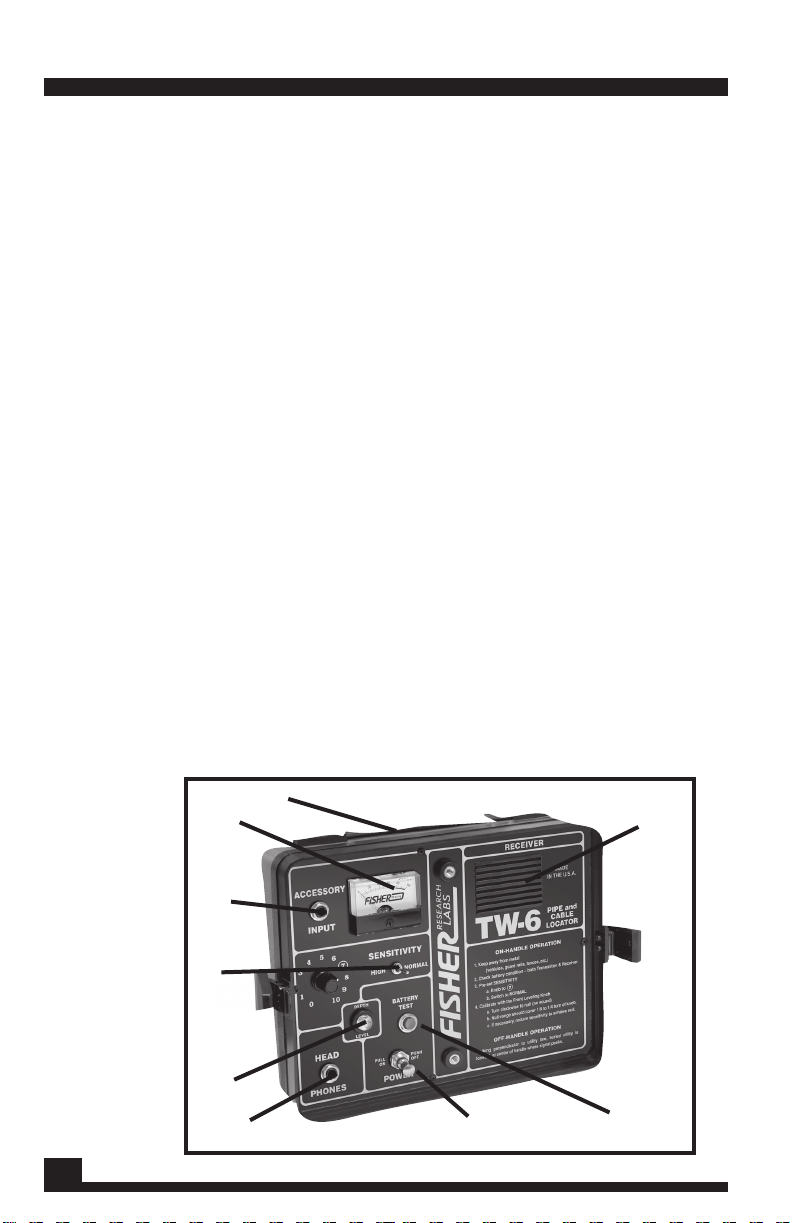
RECEIVER
1. Carrying Strap: Keeps one hand free for marking
ground or pavement while using Tracer Probe.
2. Meter: Indicates signal strength up to a point
from metallic conductors while locating or tracing.
Meter also gives a visual indication of battery
strength.
3. Accessory Input: Use this jack to plug in all
accessories except the headphones.
4. Sensitivity:
A. Toggle switch to select NORMAL or HIGH
range.
B. Knob to control sensitivity level within the
NORMAL or HIGH range.
5. Depth Level: This bubble indicates the angle of
the receiver to the ground. Use it to keep Receiver
and Transmitter level during Inductive Locating
and for making the 45-degree angle necessary in
depth determination.
6. Headphones: Use this jack to plug in
headphones only. It automatically silences
speaker. Use in particularly noisy areas.
7. Battery Test: Turn unit ON then press this red
button and observe battery strength on meter. If
meter reads below 80, replace receiver batteries.
Usually transmitter & receiver batteries are
9
1
2
3
4
7
8
6
5
Page 5
1 2
3
replaced at the same time.
8. Power: Pull out for ON, push in for OFF.
9. Speaker: Produces the audible signal, which
increases in volume and pitch as signal strength
increases. The volume and pitch increase even
after the meter has peaked at 100.
RECEIVER
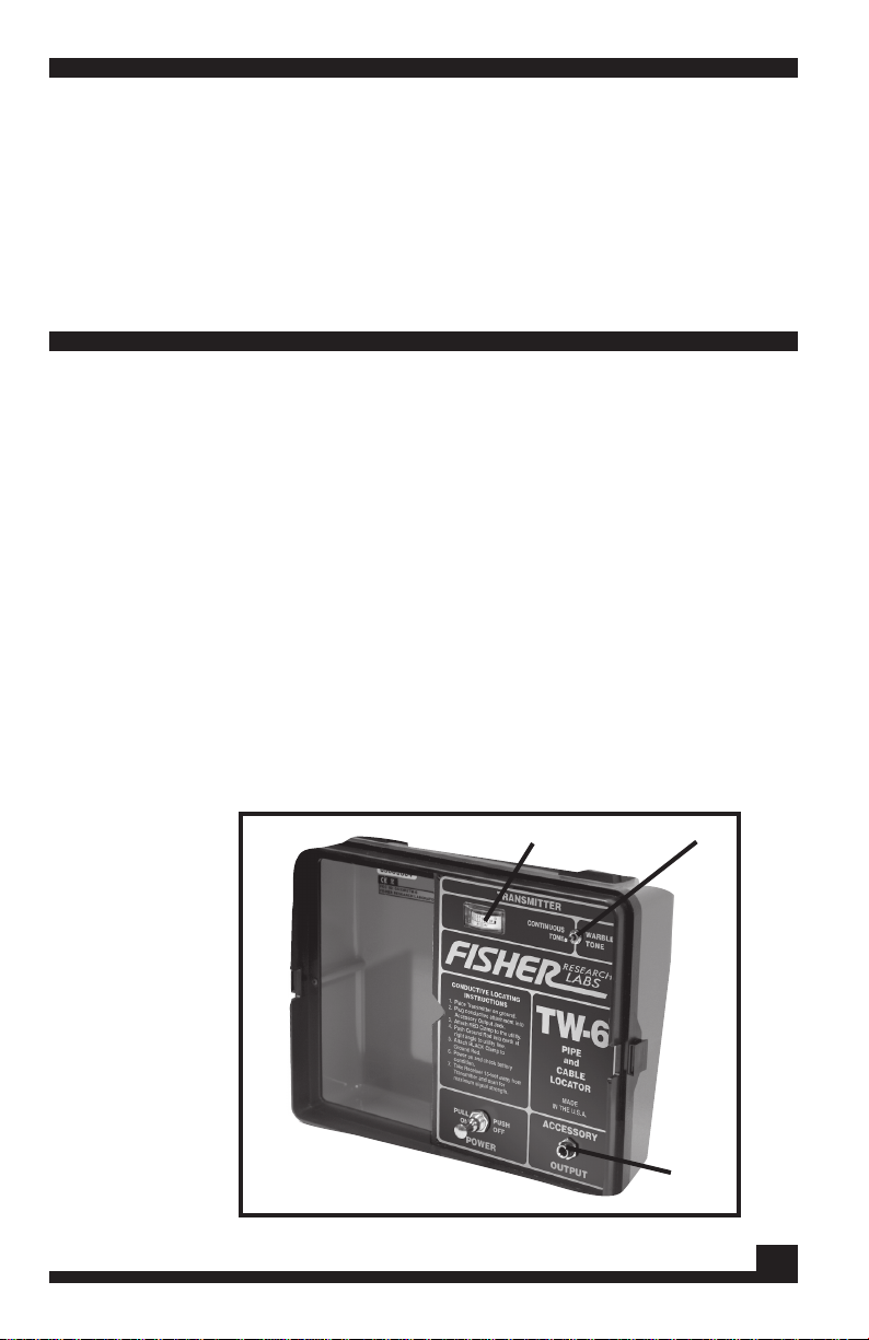
TRANSMITTER
1. Battery Test Meter: Gives a visual indication of
battery strength. Battery test is activated
automatically when unit is turned ON.
2. Constant Signal/Warble Tone Switch:
A. When toggle switch is in left position a constant
signal is generated/transmitted.
B. When Toggle Switch is in right position, the TW6
generates a warble tone. This results in a pulsating
sound and an oscillation of the needle between
zero and 100.
5
Page 6

6
3. Accessory Output: The Ground Plate Assemblies
Coupling
Clamp or Ground Rod Assembly connects into
this jack for a Conductive Trace or Direct Induced
Trace.
TRANSMITER
COMPONENT DESCRIPTIONS
1. Ground Rod/Harness Assembly: Provides a
“ground” for greatest efficiency in CONDUCTIVE
TRACING. For hard ground, the accessory GroundRod /Harness Assembly is recommended.
2. 3-Piece handle: For use in INDUCTIVE LOCATING.
3. Handle Carrying Strap: Allows you to lower handle
closer to the ground for greater depth penetration
and sensitivity in locating. The same strap is used for
carrying the receiver.
4. Handle Carrying Case: Protects 3 piece handle
and makes a neater bundle.
5. Carrying Case: Sturdy protection for your TW6 and storage for accessories, such as coupling
clamp, headphones, mini probe, and ground plate
assembly.
6. Headp hones: Stereotype headphones are
available for the TW-6. They are switch selectable
from monaural to stereo and may not work with the
TW-6 when switched to mono. You may prefer to use
the stereo phones because volume is adjustable
separately to each ear. The VCO sound is shrill and
without a volume control on the mono headphones,
the sound may be uncomfortable.
Page 7
MODES OF OPERATION
Your Fisher Model TW-6 allows two modes of operation: INDUCTIVE
and CONDUCTIVE. In the INDUCTIVE mode, the Transmitter
induces the electromagnetic eld around the object sought.
The Transmitter radiates this eld through both soil and water.
INDUCTIVE is subdivided into two modes: (1) On the handle for
LOCATING and (2) Transmitter placed on the ground directly
above and in line with the conductor for TRACING and the path
of the conductor.
The CONDUCTIVE mode operates when you connect the
Transmitter directly to an exposed portion of the pipe or cable in
question with the Ground Plate Assembly, or with the Coupling
Clamp, or the Ground Rod Assembly.
THE INDUCTIVE MODE
HOW TO ASSEMBLE
1. If you have the 3-piece handle, insert the two
end sections into the central section and turn the
knobs until they are “nger-tight”.
2. Place the Transmitter on its back and insert
handle end with one screw into V-shaped slot.
3. Turn the knob until it is “nger-tight”.
7
Page 8

MODES OF OPERATION
4. With the Transmitter still on its back, align the two
holes in the panel of the Receiver with the knobs.
5. Turn the lower knob of the two knobs until it is
“nger-tight”. Turn the knob with the arrow until the
spring is compressed and the panel is pulled within
3/8” of the handle at the end.
HOW TO TUNE
1. C h eck ba t teries on bo t h Transmitter and
Receiver.
2. Place the Receiver Sensitivity Switch in the
NORMAL position.
3. Turn SENSITIVITY knob to 7.
4. To turn ON, pull POWER switches on Receiver and
Transmitter.
5. Pick the unit up by the handle and balance it so
that it is level with the ground and at normal carrying
height (arms length). For a deeper search, hold with
the carrying strap which has been fully lengthened.
You will need to hold the instrument at this lower level
while tuning if you plan to use it lowered. On some
highly mineralized ground and some asphalt, you
may not be able to use it with strap fully lengthened.
You will know this if you cannot reach a “null”. Not
reaching a null can also indicate the presence of
nearby metal.
CAUTION: Never attempt to tune the TW-6 in the presence of metal
objects like cars, metal walls, roofs or heavy metal reinforcements
in any structure. Their presence will make proper balancing
impossible.
6. Turn front knob on handle counter-clockwise, until
lowest meter and speaker indications are reached.
You have reached the lowest point if a 1/8- l/4th turn
in either direction results in an increase in sound and
meter reading. If at the lowest point there is still sound
8
Page 9

MODES OF OPERATION
and meter reading, turn down sensitivity slowly until
meter goes to zero.
If you can turn the front knob more than l/4th turn
without an increase in sound and meter reading,
turn the sensitivity knob up from 7 to 8 and try again,
going through the null area making sure it does not
exceed l/4th turn. You may need to readjust the
sensitivity knob to give you a zero reading at the
balance.
CAUTION: Keep away from cars, fences and metal
objects during this procedure.
You are now ready to locate. Crossing over buried
metal causes an increase in sound and meter
reading.
9
Page 10

MODES OF OPERATION
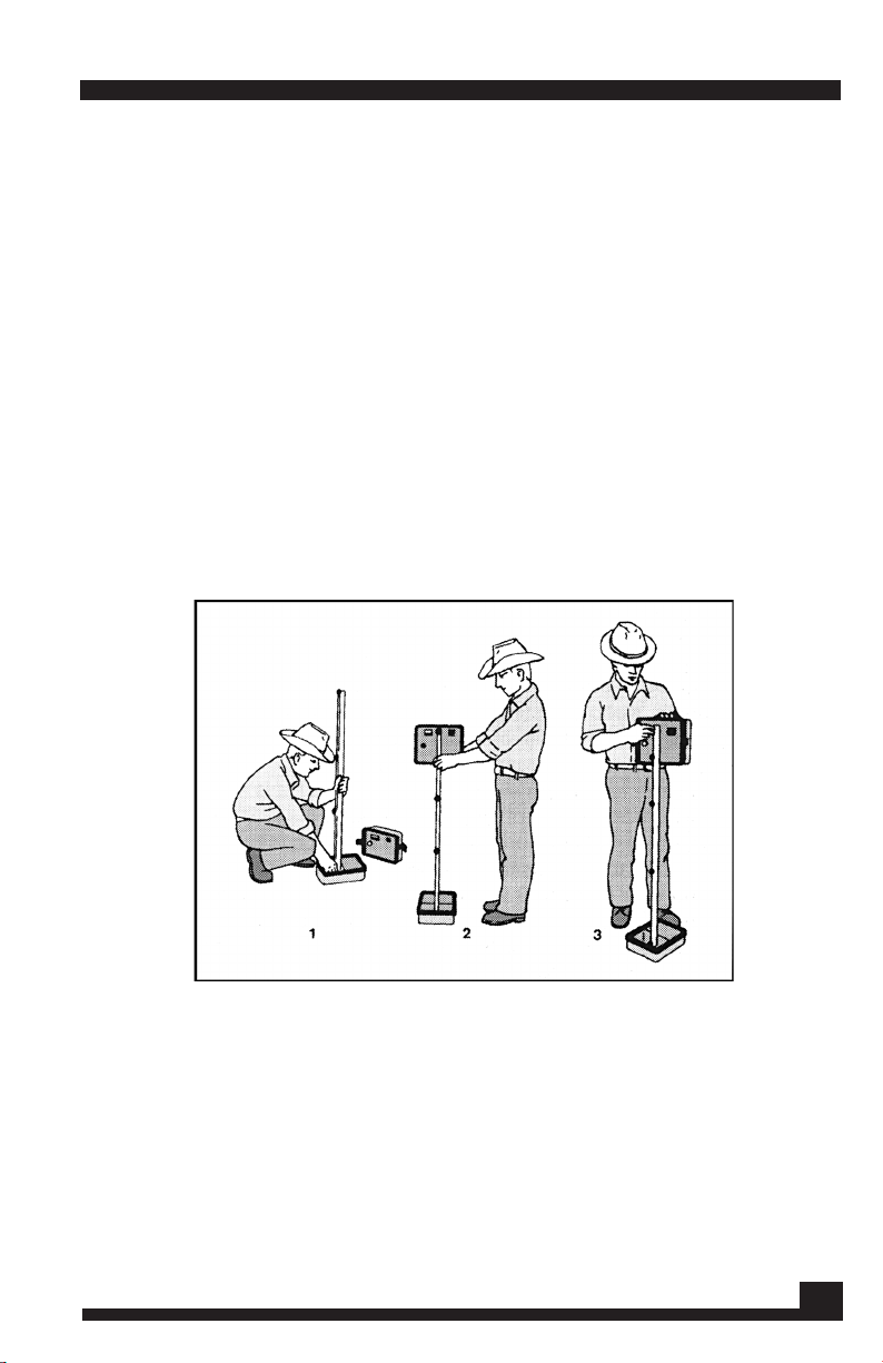
INDUCTIVE LOCATING (with handle)
Use Inductive Locating when you want to nd metal objects or
locate lost or unknown metal pipes and cables. Walk at a right
angle toward what you assume to be the conductor’s position. As
you near the conductor, the speaker sound and meter indication
will increase. They will reach maximum readings when you are
directly over the conductor. Remember, on the TW-6, unlike
earlier models, the sound volume and pitch increases far higher
than when the meter peaks. This will allow you to do most of your
locating without several readjustments of the Sensitivity knob.
As you cross over, the indications will begin to decrease because
you are moving away. To get a precise x on the location, make
a mark at your feet when readings reach their maximum. Cross
over the pipe, turn around and come back. Make a second mark
when readings return to maximum. Measure between the two
marks and bisect the distance. That is where the conductor is.
To establish the path of a pipe or cable (conductor) move “up”
and “down” the line 15 or 20 feet and locate again. From these
three locations you should be able to draw a straight line (unless
pipe has turned). Careful additional locations may be necessary
if no prints of the area are available.
It may be necessary to reduce sensitivity with the knob when the
pipe or cable is large and/or shallow. If the meter needle has
peaked and sound is at a high level, you will want to bring the
sensitivity down to see the peak of the needle at a point less than
100 as you move in half or quarter steps back and forth to get
your peak reading.
10
Page 11

MODES OF OPERATION
HIGH POWER (with handle)
An interesting phenomenon on the TW-6 compared to the TW-5
and an earlier model is that you may prefer to use it in HIGH power,
on-the-handle. The Sensitivity knob will need to be lowered to
about 3 or slightly less to get the meter reading down to zero and
no sound when balancing. As you approach a pipe or cable lying
beneath the ground, the signal may be slight, approximately 20
to 30 and it can be difcult to identify the peak.
Now turn the Sensitivity knob up so the meter reading becomes
70-75. As you move forward and backward, you will easily see
a peak on the meter. Mark the spot on the ground where you
have stopped, with both feet together. Then go on beyond the
conductor, turn around and approach the conductor in the same
way, stopping with feet together at the highest meter reading and
mark the spot on the ground. Measure between the two points,
bisect it and you have the centerline of the conductor.
Be aware that when you use HIGH power on the handle, you will
need to be further away from vehicles, metal buildings and metal
fences to avoid sensing them as well.
11
Page 12

MODES OF OPERATION
INDUCTIVE TRACING (without handle)
Use Inductive Tracing as a one-man operation when you know a
starting point of the object pipe or conductor. You will maximize
signal strength by having the bottom edge of the Transmitter
directly over and in line with the conductor you’re tracing. Placing
the receiver on its back will give no signal or a “null” directly over
the conductor and a signal on either side.
If you place the transmitter and receiver too close together “direct
air coupling” will result, meaning the transmitter is sending to the
receiver through the air, the electromagnetic eld is simply ignoring
your pipe. If this happens, you can either (1) turn the SENSITIVITY
control down until you lose the air signal, or (2) simply move the
receiver further away until the air signal fades.
NOTE: With the SENSITIVITY knob on full and the Sensitivity Selection
Switch set to NORMAL, the two units should be at least 30 feet
apart to avoid air coupling. With HIGH SENSITIVITY, they must be
even further apart.
12
Page 13

MODES OF OPERATION
INDUCTIVE LOCATING WHEN ONLY APPROXIMATE POSITION
OF A LINEAR CONDUCTOR IS KNOWN
Two people most efciently perform this operation. Each holds the
unit with its face towards him and parallel to the other’s instrument.
Standing at least 30 feet apart, they walk parallel to each other
from the curb toward the opposite side of the street. When the
two operators are directly over the pipe, the receiver meter and
speaker will indicate the location. The pipe is directly below the
point at which the maximum signal occurs.
If only one operator is available, he should begin by placing the
transmitter over and in line with an assumed position of the buried
conductor. While maintaining a distance of at least 30 feet from
the transmitter, hold the receiver parallel to the other instrument
and begin to walk forward until the signal reads its maximum
indication. In a one-person search, you may nd it necessary to
move the transmitter several times in order to be precisely over
the buried conductor.
PINPOINTING CENTER OF THE PIPELINE
After determining the position of the pipe, set the transmitter down
on its bottom edge and in line with the indicated position. Then, at
a distance of at least 30 feet, hold the receiver with its backside
down and begin moving the receiver from side to side over the
general location line of the conductor. This back and forth motion
will give a null directly over the position of the buried conductor.
13
Page 14

MODES OF OPERATION
DETERMININING CONDUCTOR DEPTH BY TRIANGULATION
This procedure is only accomplished when the transmitter is close
enough for the receiver to receive a strong and clear signal.
Once you have determined the exact centerline of the conductor
(either Inductively or Conductively), place the receiver above and
parallel to it. Hold the receiver as close to the ground as possible.
Now, tip the receiver back until the bubble inside the depth level
indicator rests between the outer edge of the center ring and the
black border of the level.
When it does, the receiver will be at a 45-degree angle to the level
ground. Care should be taken at this point, as a few degrees of
deviation will affect the nal depth analysis. The operator should
be holding the receiver at 45 degrees and facing toward the
conductor centerline. Now, back away slowly, at a right angle
to the conductor, keeping the bubble as steady as possible. The
meter indication should manually be adjusted by means of the
sensitivity control to stay on scale in order to observe the point
where the needle will fall to a minimum signal. After this point, the
signal begins to increase again.
Position the receiver at the minimum or null point. Measure the
horizontal distance from the centerline of the conductor to center
of the fastener, which holds transmitter and receiver together. This
distance, minus the distance of the center of the locator loop
above the ground distance (5”) is the depth of the conductor.
If the conductor is buried in sloping ground, make a depth
determination on each side of the conductor and average the
two distances to nd the cable depth.
A tracer probe with its smaller receiver coil in the tip, is quicker
and easier to use, hence it yields greater accuracy in depth
nding and tracing. The same principle of triangulation is used
when using the receiver or receiver with tracer probe.
14
Page 15

MODES OF OPERATION
LOCATING MANHOLE COVERS, VALVES, TEES AND RISERS
These jobs are best performed in the Inductive Mode using the
handle. To nd a valve, tee or riser, locate the main pipe using any
of the previously discussed methods, then, holding the center of
the handle with the receiver leading (face up), walk alongside the
main pipe. Be sure you’re far enough away from the centerline of
the pipe to have a low or no reading. When you cross the sought
after valve, tee or riser, the meter and speaker will signal a larger
mass of metal indicating the valve. At that point, you can cross
and return over the suspected valve location from 3 or 4 directions
to pinpoint its location.
In the case of the paved-over manhole cover, search systematically
by walking out a grid pattern, each “line” of which should be 4
feet apart. Practice this grid technique with a visible cover so that
you can get the “feel” of it.
LOCATING PIPE WHEN OTHER LINES ARE CLOSE BY
Two methods of Inductive Tracing may be employed. In the rst
method, set the transmitter vertically and parallel to the line to
be traced, approximately three to ve feet from the pipe you’re
tracing and away from the pipe not wanted.
Now, follow normal Inductive Tracing instructions. To locate the
other pipe, move the transmitter to the opposite side, three to ve
feet away from the second pipe. In the second method, set up
the transmitter so that its plane points toward the pipe desired.
This positioning induces a maximum eld in the pipe desired and
a minimum eld in the secondary pipe.
15
Page 16

MODES OF OPERATION
CONDUCTIVE TRACING (without handle)
The most satisfactory method of tracing when you need to trace
an individual pipe when another pipe is nearby is CONDUCTIVE
tracing. In the CONDUCTIVE mode, the transmitter energizes the
pipe through direct connection. Before attaching the ground rod
clamp to the conductor, clean the conductor with a wire brush
(this creates a good metal-to-metal contact).
After cleaning, plug the jack into the transmitter and secure the
clamp to the pipe or non-energized cable. Place the transmitter
in an upright position and as far away from the pipe as possible to
the side opposite any other lines. As far away as possible means
it will be at 90”.
If you are working in an area with several other conductors near
the pipe or cable you want to trace, place the ground plate as
close as possible to the point at which you fasten the clip to the
pipe or cable. This will reduce the signal strength and reduce the
amount of signal induced into another nearby conductor, giving
a more concentrated signal in the pipe or cable you are tracing.
Never stretch the ground plate across a conductor running parallel
to the pipe or cable you are tracing, because even if you are
not hooked up to the conductor you crossed over, the signal has
16
Page 17

MODES OF OPERATION
to cross back past the path of this conductor and will induce a
certain amount of signal into it. This signal can mislead you when
tracing it out.
If you’re working on pavement, simply lay the Ground Rod/
Harness Assembly on its side, parallel to the conductor in
the direction of the tracing. Weighting it down with a rock or
someone standing on it makes it a better ground contact. If the
plate is weighted down in a puddle or at least if the pavement
is wet, tracing distance is improved. You may pour some water
on the pavement to improve ground contact.
17
Page 18

TRACING PROCEDURE
Turn the transmitter ON and turn receiver SENSITIVITY knob all the
way up in NORMAL. Then, when the conductor is located, turn
SENSITIVITY down to get a precise indication of the location. Use
NORMAL for ordinary tracing, HIGH for extended tracing. In the
Conductive Mode, you can have Transmitter and
Receiver as near to each other as 20 feet apart and closer yet
if you use the Tracer Probe, without air coupling occurring. With
HIGH power, the distance increases.
With settings and connections completed, the operator need only
walk out his trace while paying attention to signal strength over
the conductor. As in the Inductive Mode, the receiver should be
carried vertically and parallel to the pipe or cable being traced.
However, once the position is discovered, you may turn the
receiver to a horizontal position to get a pinpoint reading.
If you’re dealing with a maze of pipes, trace each line and mark
its surface location on pavement with colored chalk or spray paint
as you locate it. Extra long yellow or white golf tees are very handy
markers when locating over turf or open ground.
Another tip...start tracing operations away from the congested
location. The pipe is then carefully traced into the desired area
with little chance of false indications. The Tracer Probe also helps
reduce spurious signals from nearby pipes and cables.
The Tracer Probe
As you trace out the pipe or cable, signal strength gradually
diminishes. When you reach the limit of NORMAL, switch to HIGH
sensitivity and adjust the sensitivity knob for a sharp null over the
conductor you are following.
The tracer probe designed especially for the TW-6 is slightly shorter
than the earlier model and does not need a separate SENSITIVITY
knob. It can be used effectively with the earlier TW-5 model. The
Tracer Probe for the TW-5 can be used with the TW-6 but reduces
tracing distance.
Once you have located the pipe or cable with a sharp “null”,
back away at right angles, dragging the tip of the Tracer Probe
on the ground and maintaining the level bubble centered in its
18
Page 19

TRACING PROCEDURE
circle. You need to be close enough to the transmitter for a strong
signal so that the sound will quit or “null” as you back away and
then resume again as you move backwards. You measure from
the middle of the null area back to the centerline of the pipe or
cable and that is its depth.
COUPLING CLAMP
Use the Coupling Clamp to Inductively energize and trace without
a metal-to-metal contact. Tracing distance will be less than when
using the ground rod assembly, so there is no advantage to using
the coupling clamp on pipes, unless a non-conductive wrapping
prevents bare metal contact.
Begin by plugging the Clamp into ACCESSORY OUTPUT on the
transmitter. Place Clamp around cable or other conductor (make
sure jaws are completely closed). Turn receiver and transmitter ON
and precede using tracing techniques as described earlier. The
conductor must make a closed loop, or circuit, or be grounded
for best tracing results.
It is useful to carry a “jumper” with two clips and a rod to be
driven into the ground to be sure of the ground. Two Coupling
Clamps can be used together to perform manhole-to-manhole
and drop-to-junction types of work. Plug the second Clamp into
receiver ACCESSORY INPUT jack. Then, test different strands with
the receiver Clamp to nd your signal.
19
Page 20

LOCATING NON-METALLIC PIPES
One method is to run an electrician’s “sh-tape” or plumber’s
“snake” down the pipe and connect the transmitter to it using
the ground plate assembly. Attach the ground plate assembly
clamp to the tape or “snake” and trace the pipe with receiver
or receiver and tracer probe. B lockages in pipes can be
located this way too in that the tracing signal will stop where
the tape or “snake” ends at the stoppage. Tracer tape which
is aluminum foil tape sandwiched in printed mylar is available
from 3 or 4 U.S. manufacturers in two-inch widths and wider. It
can be laid into the trench above a non-metallic pipe. When
laid according to the tape manufacturer’s instructions, the tape
and hence pipe can be located Inductively or Conductively.
When laid only 8” or 10” below the surface, it can also be
traced with a valve and box locator such as a Fisher M-66 or
M-97.
20
Page 21

OPERATING HINTS
To develop your operator technique, practice with known
pipes and cables to thoroughly familiarize you with your TW-6.
Of particular importance in this regard is the SENSITIVITY knob.
Learning to vary the SENSITIVITY knob and studying the effects of
those variations remains the key to getting the most precision out
of the instrument. These practice sessions will not only allow you to
get used to how the TW-6 responds to different kinds of pipes and
cables, but it will also teach you how to interpret each reading.
When using the TW-6 on the handle in the presence of CONDUCTIVE
SOIL (those with high mineral salt content and usually rather
damp), it may be necessary to turn down the SENSITIVITY control
from the suggested position. With each repeated reduction, the
operator should readjust the front knob as given in the “How To
Tune” instructions.
When locating near-surface and/or very large pipes, you can
sharply decrease the width of indication by tuning the SENSITIVITY
control down or counter-clockwise. This narrowing of the indication
will allow more accurate pinpointing.
The TW-6 has a slightly slower response than earlier models. This is
more noticeable at extended tracing ranges. Be sure that when
you “wag” either the receiver or the Tracer Probe, you do so
slowly enough for the receiver to sense the signal emitted by the
underground pipe or cable.
If the signal remains reasonably strong as you are tracing out a
pipe or cable and it mysteriously disappears, use the “null method
“of locating with the receiver instead of the “signal method”.
Sometimes at extended ranges in HIGH power, the “null-method”
will give you greater tracing distance, however, usually the signal
method will give a longer trace.
21
Page 22

CHANGING BATTERIES
Turn the instrument over on its face (position is the same for both
transmitter and receiver) and remove access plate with coin or
large blade screwdriver.
Lift the battery pack out carefully. Turn the battery pack slightly
and unsnap the battery connector. Change all eight batteries.
Then reattach the connector to the pack. Slip the battery pack
back into its compartment and do battery test. Refasten the
access plate.
Both the transmitter and receiver will work from 30 to 40 hours on
a set of 8 standard quality AA batteries. Alkaline batteries will give
at least 30 to 40% greater life. In cold weather, alkaline batteries
are much livelier than standard carbon zinc batteries.
WARNING: Batteries can contain hazardous materials and must
be disposed according to the laws in your country.
CAUTION: Do not try to recharge the batteries that come with the
TW-6, or any other batteries, except Ni-Cad rechargeables.
22
Page 23

23
SPECIFICATIONS
Operating Frequency .........81.92 kHz +.005% .....81.92 kHz +.005%
Batteries
................................8 each, AA (NEDA 15) 8 each, AA
(NEDA 15)
Weight
..................................2 1/2 lbs. (1.1 kg) ......... 3 lbs. (1.36 kg)
Sensitivity
..............................N/A Normal: 400 uV typical High: 8 uV
typical
Signal-to-noise ratio
............N/A ............................................. 110dB
Headset Impedance
.......... N/A ......................... 600 ohms (mono)
N/A .............................. 8 ohms (stereo)
Dimensions
...........................11 1/2” x 9” x 3 ...........11 1/2” x 9” x 3”
(29 x 23 x,.7.6 cm)
................(29 x 23 x 7.6 cm)
Operating Temperature
..... -1O0F to +1200F, (-230C to +480C)
depending on batteries used.
Total Weight
.........................5 1/2 lbs. (2.5 kg)
-(without handle or accessories, ground plate assembly or operating manual).
Total Shipping Weight
...............................................6 3/4 lbs. (3 kg)
-(including only ground plateassembly and operating manual.)
Total Shipping Volume
....................................69 cu. ft. (119.5 liters)
Field Strength: 17.5dBuV @ 300 meters, 81.92KHz.
Transmitter Receiver
Using headphones (not supplied) improves battery life, and
prevents the sounds from annoying bystanders.
It also allows you to hear subtle changes in the sound more
clearly, particularly if searching in a noisy location. For safety
reasons, do not use headphones near traffic or where
other dangers are present. This device is to be used with
interconnecting cables/headphone cables shorter than three
meters.
USING HEADPHONES
Page 24

Q U A L I T Y
Fisher detectors are renowned for their quality.
Each detector is hand crafted in the USA with pride
P E R F O R M A N C E
The worldwide underground utility industry relys on Fisher.
Our instruments are durable, dependable, and locate deeper.
R E P U T A T I O N
Fisher produced the rst patented metal detector in 1931. For
over 70 years, the Fisher logo has been a mark of excellence.
2 - YEAR LIMITED WARRANTY
Fisher believes in the products we produce and backs this belief
with a 2 year limited warranty.
Proof of purchase is required to make a claim under this warranty.
NOTE TO CUSTOMERS OUTSIDE THE U.S.A.
This warranty may vary in other countries, check with your distributor for details.
Factory warranty follows the channel of distribution.
Warranty does not cover shipping costs.
According to FCC part 15.21 Changes or Modications made to this device
not expressly approved by the party responsible for compliance could void
the users authority to operate this equipment.
S E R V I C E
Fisher is committed to providing you, our valued customer, with
superior service. Each and every instrument is rigidly tested
and carefully inspected during assembly and before shipment.
Should you have any questions or problems, contact:
FISHER RESEARCH LABORATORY
1465-H Henry Brennan,
El Paso, Texas 79936
Tel 915.225.0333 Fax 915.225.0336
www.sherlab.com email:info@sherlab.com
FRL#8700241
07-21-10
 Loading...