

Page 1
Instruction Manual
D103796X012
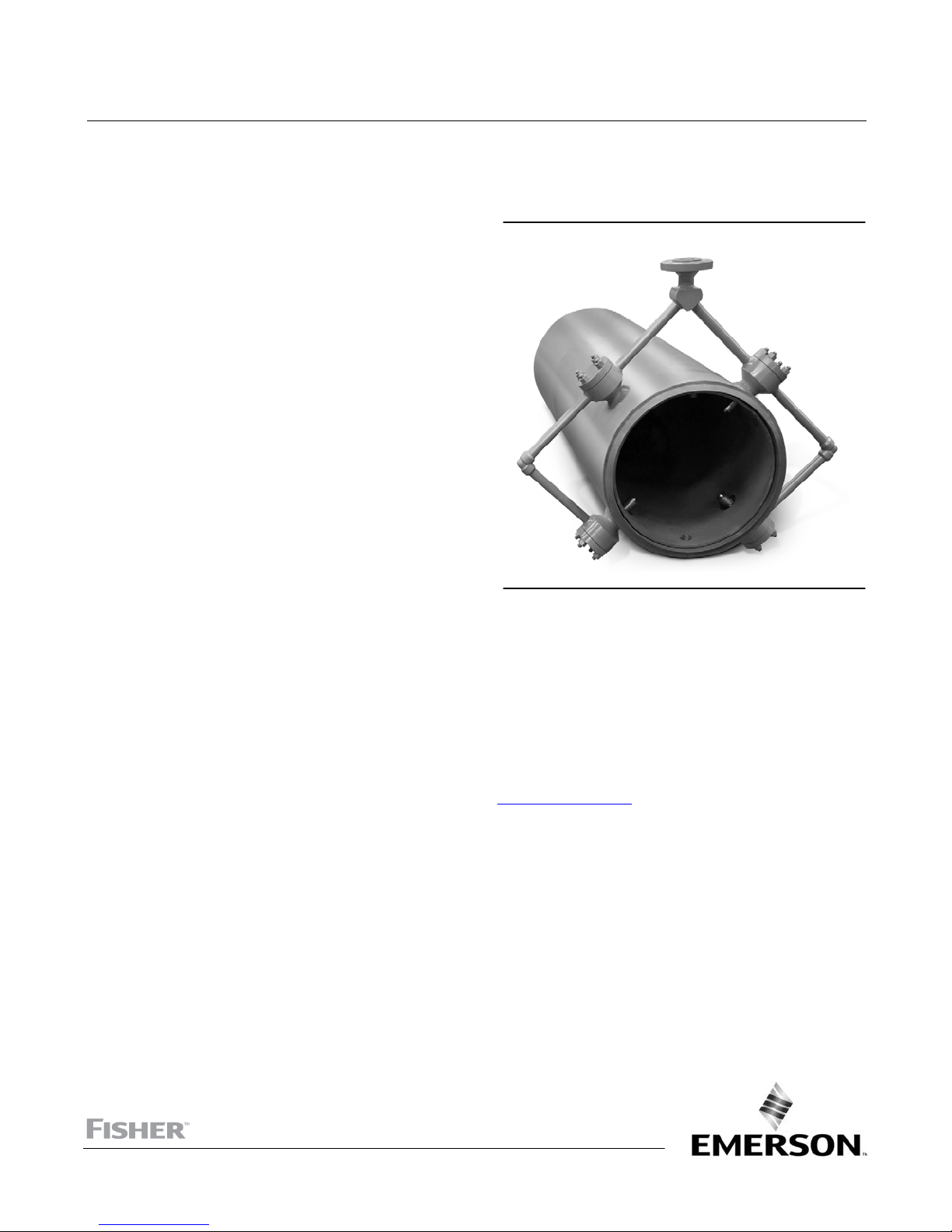
Fisher™ TBX-T Desuperheater
TBX-T Desuperheater
July 2017
Contents
Introduction 1.................................
Scope of Manual 1.............................
Description 1.................................
Educational Services 2.........................
Installation 3..................................
Maintenance 5.................................
Servicing 5...................................
Parts Ordering 9................................
Parts List 9....................................
Introduction
Scope of Manual
Figure 1. Fisher TBX-T Desuperheater
X0162
This instruction manual includes installation, maintenance, and operation information for the Fisher TBX-T
desuperheater. Refer to separate instruction manuals for instructions covering the actuator and accessories.
Do not install, operate, or maintain a TBX-T desuperheater without being fully trained and qualified in valve, actuator,
and accessory installation, operation, and maintenance. To avoid personal injury or property damage, it is important
to carefully read, understand, and follow all the contents of this manual, including all safety cautions and warnings. If
you have any questions about these instructions, contact your Emerson sales office
proceeding.
or Local Business Partner before
Description
Water atomization and vaporization are key elements in any steam conditioning application. The TBX-T design
incorporates a spraywater manifold of variable geometry AF nozzles that produce an optimized spray pattern over a
wide operating range. These nozzles are strategically placed to achieve optimal mixing and quick vaporization at all
flowing conditions. Years of research in spray atomization and vaporization were key to optimizing the water injection
system. Extensive use of CFD analysis, in addition to field performance feedback, was used to validate spray system
enhancements.
www.Fisher.com
Page 2

TBX-T Desuperheater
July 2017
Table 1. Specifications for Standard Designs (Physical Specifications)
Instruction Manual
D103796X012
Steam Line Connection Sizes
NPS 8 through NPS 48
Steam Line Connection Types
J ASME Buttweld (all sizes)
J ASME Raised Face Flanges (all sizes)
J ASME Ring Type Joint Flanges (all sizes)
Construction Materials
Steam Pipe:
F22 (2-1/4 Cr-1 Mo)
J SA105 carbon steel, J SA182 Grade
J SA182 Grade F91 (9 Cr-1
Mo-V)
Nozzles:
Gaskets:
1. Do not exceed the pressure or temperature limits in this instruction manual, nor any applicable code or standard limitations.
2. A function of required turndown and equipment selection.
J S41000 stainless steel
J N06600/Graphite
(1)
Bolting:
J N07718
Spraywater Connection
J NPS 1 through NPS 4
J ASME Raised Face Flange (all sizes)
J ASME CL150 to CL2500
Maximum Inlet Pressures
J SA193 Grade B7, J SA193 Grade B16,
(1)
(1)
Consistent with applicable pressure-temperature
ratings per ASME B16.34
Spraywater Pressure Required
(2)
3.5 to 35 bar (50 to 500 psi) greater than steam line
pressure
Educational Services
For information on available courses for Fisher TBX-T desuperheaters, as well as a variety of other products, contact:
Emerson Automation Solutions
Educational Services - Registration
Phone: 1-641-754-3771 or 1-800-338-8158
E-mail: education@emerson.com
emerson.com/fishervalvetraining
2
Page 3
Instruction Manual
D103796X012
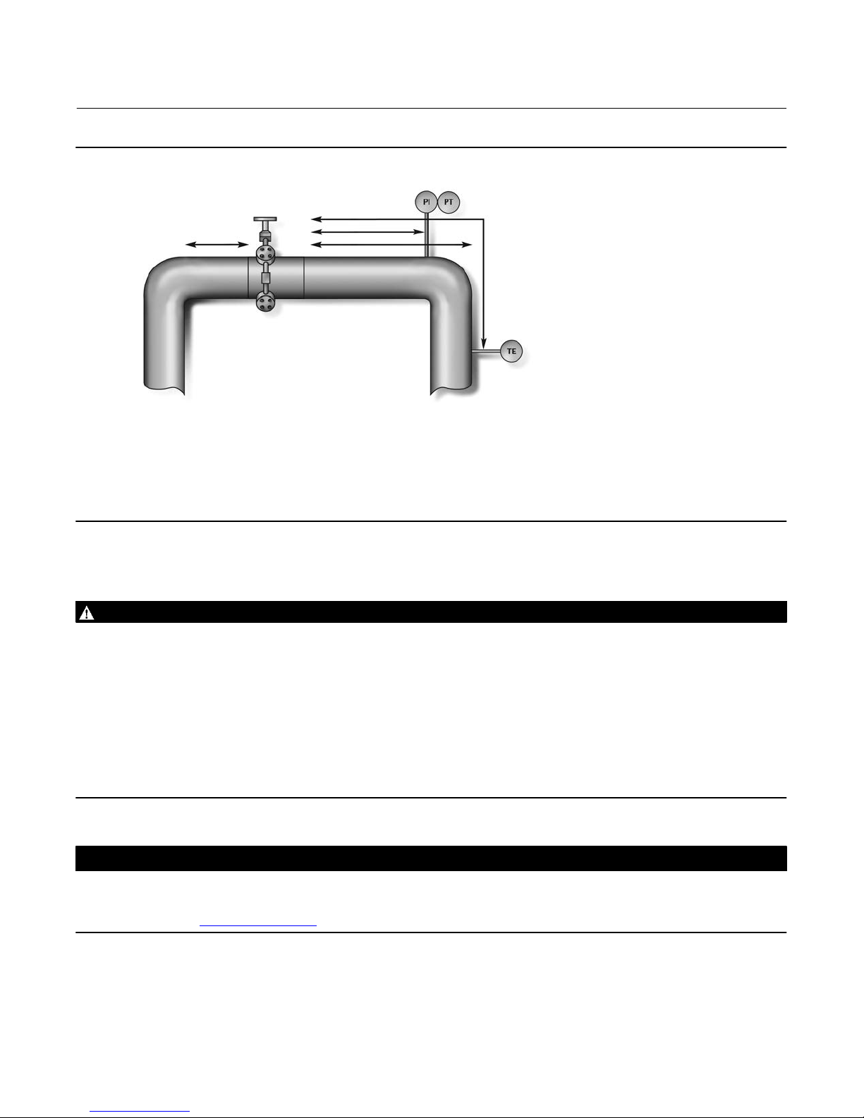
Figure 2. Typical Fisher TBX Installation
USPL
KEY:
DSPL = DOWNSTREAM STRAIGHT PIPE LENGTH
PI = PROPORTIONAL INTEGRAL CONTROLLER
PSL = PRESSURE SENSOR LENGTH
PT = PRESSURE TRANSMITTER
TE = TEMPERATURE SENSOR ELEMENT
TSL = TEMPERATURE SENSOR LENGTH
X0355
USPL = UPSTREAM STRAIGHT PIPE LENGTH
TBX-T Desuperheater
July 2017
TSL
PSL
DSPL
Installation
WARNING
Always wear protective gloves, clothing, and eyewear when performing any installation operations to avoid personal
injury.
Personal injury or equipment damage caused by sudden release of pressure may result if the TBX-T desuperheater is
installed where service conditions could exceed the limits of the pressure rating noted on the nameplate. To avoid such
injury or damage, provide a relief valve for over pressure protection as required by government or accepted industry codes
and good engineering practices.
Check with your process or safety engineer for any additional measures that must be taken to protect against process
media.
If installing into an existing application, also refer to the WARNING at the beginning of the Maintenance section in this
instruction manual.
CAUTION
When ordered, the desuperheater configuration and construction materials were selected to meet particular pressure,
temperature, pressure drop, and fluid conditions. Do not apply any other conditions to the desuperheater without first
contacting your local Emerson sales office
1. Before installation, all piping upstream of the valve must be blown clean so that no loose materials such as welding
slag, dirt or other foreign matter, are left in the pipe. Use care to keep foreign matter out of the line openings while
preparing the valve installation.
or Local Business Partner.
3
Page 4

TBX-T Desuperheater
July 2017
Instruction Manual
D103796X012
WARNING
Do not lift the desuperheater by its cooler manifold piping. Personal injury or damage to equipment could occur if the
desuperheater is improperly lifted into place.
If the TBX-T is equipped with buttweld ends, the valve body must be supported using a lifting sling or other method that
does not place a load or force onto the finished surface of the buttweld ends. The TBX-T does not have a stable resting
condition. The valve inlet and outlet must be fully supported until fully welded (buttweld end connections) or bolted
(flanged end connections) into the piping.
2. Arrange a lifting sling around the main steam pipe to safely lift the TBX-T to the pipe opening.
WARNING
Do not expose the TBX-T to undue stresses by installing it in bent pipes or flanges. Personal injury and equipment damage
could result from flange sealing failure due to improper installation.
3. Flanged Connections—Grease the flange connection bolts with a high temperature thread lubricant. Install flange
gaskets and connection bolts per accepted practices and tighten securely.
4. Welded Connections—Welding procedures should be in accordance with the applicable codes and the base
materials. For preheat, welding electrodes, and postweld heat treatment, refer to the applicable codes and
practices applicable for the specific facility. Materials are specified on the customer specification sheet.
CAUTION
Depending on desuperheater body materials used, post weld heat treating may be required. If so, damage to internal parts
is possible. In general, if post weld heat treating is to be performed, all nozzles should be removed. Contact your Emerson
sales office or Local Business Partner for additional information.
5. Remove the spraywater control valve and flush the cooling water line until all debris is removed from the line prior
to connecting it to the TBX-T desuperheater. Use only clean sources of cooling water to reduce the possibility of
nozzle clogging. A 100 mesh strainer should be installed in the water line as close to the TBX-T desuperheater as
possible. Review strainer manufacturer's pressure drop curves to determine appropriate strainer body size. You may
need to use a strainer that is larger than the water line size.
WARNING
Failure to use a strainer could result in nozzle clogging and subsequent property damage or loss. Uncontrolled
temperatures resulting from clogged nozzles may result in equipment or process temperature limits being exceeded.
Exceeding system temperature limits could result in property damage or personal injury.
6. A length of straight pipe is required downstream of the TBX-T desuperheater to ensure complete vaporization of
cooling water. An example of a typical installation appears in figure 2. Consult the TBX-T cooler sizing sheet for the
required distance of straight pipe. This is unique for each application and is supplied by Emerson Automation
Solutions.
7. Typically, a temperature sensor should be mounted a minimum distance of 9.1 m (30 feet) downstream of the
TBX-T desuperheater. This distance will vary depending on a number of factors including steam velocity and
4
Page 5

Instruction Manual
D103796X012
TBX-T Desuperheater
July 2017
percentage of spraywater. Consult the TBX-T cooler sizing sheet provided with the unit for this temperature sensor
distance. The steam line should not have any branch lines dividing the steam flow between the TBX-T
desuperheater and the temperature sensor. If you have any questions, contact your local Emerson sales office
or
Local Business Partner.
8. A typical installation is illustrated in figure 2. A temperature sensor (TE) measures changes in temperature and a
temperature transmitter (TT) transmits the signal to the temperature control device. The output signal from the
controller is sent to the positioner on the cooling water (spraywater) control valve (SWCV). The positioner's output
signal strokes the SWCV open, increasing water pressure on the nozzles. Increasing water pressure upstream of the
nozzles increases water flow through the nozzles.
CAUTION
Pneumatic lines (where applicable) should be thoroughly blown clean with dry air before connection. Check electronic
lines for correct connection.
Maintenance
Table 2. Inspection Summary
Key Part Description Inspection Tips and Diagnostics Repair Replacement
1
2
3 Nozzle Sleeve
7 Nozzle Body Flange
10 Spray Nozzle Refer to Nozzle Maintenance Section.
Steam Pipe
(not replacement part)
Nozzle Body
(not replacement part)
Servicing
WARNING
Avoid personal injury or property damage from sudden release of process pressure or bursting of parts. Before performing
any maintenance operations:
D Always wear protective gloves, clothing, and eyewear when performing any maintenance operations to avoid personal
injury.
D Use bypass valves or completely shut off the process to isolate the desuperheater from process pressure. Relieve
process pressure from both sides of the valve. Drain the process media from both sides of the desuperheater.
D Use lock‐out procedures to be sure that the above measures stay in effect while you work on the equipment.
D Check with your process or safety engineer for any additional measures that must be taken to protect against process
media.
Inspect for erosion, thermal fatigue, and other
damage.
Inspect for erosion, thermal fatigue, and other
damage.
Inspect for particulate or magnetite buildup when
spray nozzles are replaced.
Inspect gasket surfaces for damage that could indicate
gasket leakage when spray nozzles are replaced.
Consult your local Emerson Service Center for a recommendation on
necessary weld repair or replacement
Consult your local Emerson Service Center for a recommendation on
necessary weld repair or replacement
Clean if necessary. As needed
Replacement Only As needed
Replacement every 24-36 months
for optimal performance
5
Page 6

TBX-T Desuperheater
July 2017
Instruction Manual
D103796X012
Nozzle Maintenance and Replacement
When subjected to normal operating conditions, it is possible that wear, blockage, and/or weld fatigue will occur to
the nozzle assembly. During regularly scheduled maintenance, visually inspect the nozzles for wear and blockage.
Your local Emerson Service Center can help to determine the extent of weld fatigue and the correct course of action.
Poor performing nozzles or nozzle failure is typically caused by wear, corrosion, erosion, and/or blockage. The
following instruction will help to determine if any of these problems are present and provide a recommended course
of action for each.
Note
For optimal performance, nozzles should be inspected every 18-24 months and replaced every 24-36 months.
1. OPTIONAL: Figure 3 shows the spray pattern that will need to be present during operation of the AF nozzles. Testing
can be performed by attaching the existing or an alternate, similar pressure, water line to the spray water input
connection. If this spray pattern is not present, replacement is recommended.
Figure 3. Fisher AF Nozzle Cross Section
SPRAY HEAD
SWIRL CHAMBER
WATER INJECTION HOLES
(COMPOUND ANGLED ORIFICES)
SPRING
PLUG STEM
SPRING CASING
PIN
A7191-2D
SPRAY PATTERN
SPRAY
ANNULUS
TRAVEL MEASUREMENT
2. Loosen and remove the nozzle body flange stud nuts (key 58) and washers (key 59). Then, remove the nozzle body
flange (key 20). Inspect the nozzle body flange gasket surfaces for damage. If damage is present replacement is
necessary.
3. Remove the nozzle sleeve (key 37) with attached spray nozzle (key 30), nozzle sleeve gasket (key 47), and nozzle
body flange gasket (key 48). Inspect the nozzle sleeve for particulate or magnetite buildup and clean if necessary.
4. Inspect the spray annulus surface, the area between the plug stem and spray head, for excessive wear,
erosion/corrosion, or blockage due to particulate. Wear is defined as any nicks, cuts, or gouges on or immediately
around the spray annulus. Erosion/corrosion is defined as any form of rust or erosion of the metal on the plug stem
or spray head. Blockages are defined when small particulate becomes trapped between the plug stem and spray
head or spring casing and spray head. Replacement of the nozzle is recommended if any of the preceding problems
are present.
6
Page 7

Instruction Manual
D103796X012
TBX-T Desuperheater
July 2017
5. Grind off the tack welds holding the nozzle (key 30) in place. Apply a penetrant type thread lubricant and allow to
soak prior to unscrewing the nozzle. Using the provided flats on the side of the spray head, unscrew the nozzle from
the nozzle sleeve (key 37).
6. Grind excess tack weld material off both the nozzle (key 30) and nozzle sleeve (key 37).
7. In the absence of external forces, the nozzle must be fully closed. If the nozzle is not fully closed, it will need to be
replaced.
8. Inspect the water injection holes for reduced or non-circular shape due to erosion. Every hole must be the same size
and shape. If any are oversized or non-circular in shape, the nozzle will need to be replaced.
9. Inspect the interior of the water injection holes for buildup of particulate or magnetite. Nozzle replacement will be
needed is any buildup is present.
Note
Complete disassembly of the nozzle is strongly discouraged, due to individual spare parts not being available.
10. OPTIONAL: The internal spring may relax over time and not provide the tensile force required to shut off and
control flow. If the nozzle spring is suspected of being too relaxed, then the nozzle should be replaced.
To further check, the spring can be removed by first removing the pin, using a small drill bit as a punch and unscrewing
the spring casing from the plug stem. The nozzle can be reassembled by following a reverse order of disassembly,
taking care to line the hole in the plug stem up with the hole in the spring casing, then pressing the pin back into place
through the two parts.
11. The travel can be determined by using a feeler gauge to measure the distance between the spray head near the
water injection ports to the side of the spring casing, as outlined in figure 3. This measurement must match the
factory set plug stem travel for the corresponding nozzle type as shown in table 3.
Table 3. AF Nozzle Specifications
NOZZLE TYPE PLUG TRAVEL, INCHES
AF7 0.014
AF10 0.028
AF14 0.029
AF17 0.034
AF20 0.036
AF24 0.042
AF28 0.048
AF32 0.056
AF35 0.065
AF40 0.063
AF44 0.069
12. Inspect nozzle threads for damage and clean if needed. If damage is present, nozzle replacement will be
necessary.
13. Rinse both the nozzle (key 30) and nozzle sleeve (key 37) to remove particulate.
14. Screw nozzle into the nozzle sleeve (key 37) and tighten just until the spray head is flat and tight against the nozzle
sleeve.
15. Tackweld a small piece of welding wire onto the nozzle sleeve (key 37) next to either of the spray head flats to
prevent rotation during service; refer to figure 4. Maintain low heat to prevent distortion of the nozzle.
7
Page 8

TBX-T Desuperheater
July 2017
Figure 4. Spray Nozzle Tack Weld Location
AF NOZZLE BODY
Instruction Manual
D103796X012
GA26453
WIRE, TACK WELD ON BOTH ENDS
16. Reassemble in the following order: nozzle sleeve gasket (key 47), nozzle body flange gasket (key 48), spray
nozzle/sleeve assembly, nozzle body flange (key 20), washers (key 59), and stud nuts (key 58). It is recommended
that the nozzle sleeve gasket and nozzle body flange gasket be replaced with new ones.
17. Torque nozzle body flange nuts as indicated in table 4.
Table 4. Recommended Nozzle Body Flange Bolting Torque
BOLT SIZE
Inch NSm LbfSft
5/8 11 170 125
3/4 10 272 200
7/8 9 394 290
1 8 550 405
1‐1/8 8 746 550
1‐1/4 8 990 730
1‐3/8 8 1329 980
1‐1/2 8 1750 1290
1. Torques for lubricated studs with heavy hex nuts.
THREADS PER INCH
RECOMMENDED BOLT TORQUE
(1)
8
Page 9

Instruction Manual
D103796X012
TBX-T Desuperheater
July 2017
Parts Ordering
Each TBX-T desuperheater is assigned a serial number. Refer to the serial number when contacting your Emerson sales
office or Local Business Partner for technical assistance. When ordering replacement parts, refer to the serial number
and key numbers for each part required. The key numbers in the Parts List and the assembly drawing in figure 5 can be
used to help in part identification.
WARNING
Use only genuine Fisher replacement parts. Components that are not supplied by Emerson Automation Solutions should
not, under any circumstances, be used in any Fisher valve, because they may void your warranty, might adversely affect the
performance of the valve, and could cause personal injury and property damage.
Parts List
Note
Contact your Emerson sales office
Ordering information.
Key Description
1 Steam Pipe
SA 105
SA 182 Grade F22
SA 182 Grade F91
2 Nozzle Body
3 Nozzle Sleeve, F22
4 Nozzle Body Flange Washer, Plated Steel
or Local Business Partner for Part
Key Description
5 Nozzle Body Flange Stud
SA 193 Grade B7
SA 193 Grade B16
SB 637 N07718
6 Nozzle Body Flange Stud Nut
SA 194 Grade 2H
SA 194 Grade 7
SB 637 N07718
7 Nozzle Body Flange
SA105
SA182 Grade F22
SA182 Grade F91
8* Nozzle Body Flange Gasket, N06600 / Graphite
9* Nozzle Sleeve Gasket, N06600 / Graphite
10* Spray Nozzle, S41000 SST
*Recommended spare parts
9
Page 10

TBX-T Desuperheater
July 2017
Figure 5. Fisher TBX-T Desuperheater
Instruction Manual
D103796X012
10
Page 11

Instruction Manual
D103796X012
TBX-T Desuperheater
July 2017
11
Page 12

TBX-T Desuperheater
July 2017
Instruction Manual
D103796X012
Neither Emerson, Emerson Automation Solutions, nor any of their affiliated entities assumes responsibility for the selection, use or maintenance
of any product. Responsibility for proper selection, use, and maintenance of any product remains solely with the purchaser and end user.
Fisher is a mark owned by one of the companies in the Emerson Automation Solutions business unit of Emerson Electric Co. Emerson Automation Solutions,
Emerson, and the Emerson logo are trademarks and service marks of Emerson Electric Co. All other marks are the property of their respective owners.
The contents of this publication are presented for informational purposes only, and while every effort has been made to ensure their accuracy, they are not
to be construed as warranties or guarantees, express or implied, regarding the products or services described herein or their use or applicability. All sales are
governed by our terms and conditions, which are available upon request. We reserve the right to modify or improve the designs or specifications of such
products at any time without notice.
Emerson Automation Solutions
Marshalltown, Iowa 50158 USA
Sorocaba, 18087 Brazil
Cernay 68700 France
Dubai, United Arab Emirates
Singapore 128461 Singapore
www.Fisher.com
12
E 2013, 2017 Fisher Controls International LLC. All rights reserved.
 Loading...