

Page 1
Fisher Engineering
78902
50 Gordon Drive, Rockland, Maine 04841-2139 • www.fi sherplows.com
August 15, 2013
Lit. No. 43583, Rev. 01
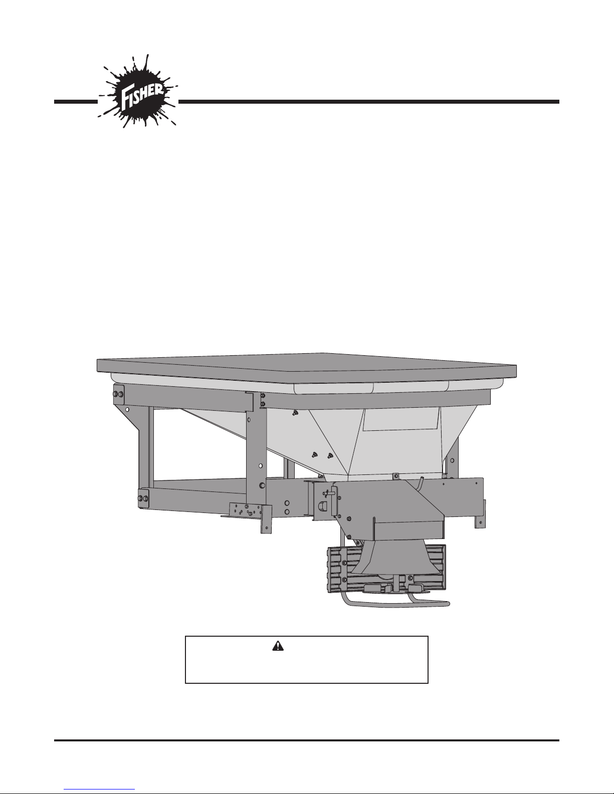
POLY-CASTER™ LT Hopper Spreader
Installation Instructions
Read this manual before installing or
operating the spreader.
These Installation Instructions are for FISHER® POLY-CASTER LT hopper spreaders with
CAUTION
serial numbers 0000 and higher.
A DIVISION OF FISHER, LLC
Page 2

Page 3
SAFETY INFORMATION
SAFETY DEFINITIONS
WARNING
Indicates a potentially hazardous situation
that, if not avoided, could result in death or
serious personal injury.
CAUTION
Indicates a potentially hazardous situation
that, if not avoided, may result in minor or
moderate injury. It may also be used to alert
against unsafe practices.
NOTE: Indicates a situation or action that can lead
to damage to your spreader and vehicle or other
property. Other useful information can also be
described.
• DO NOT EXCEED GVWR OF VEHICLE
• DO NOT OVERLOAD SPREADER
• LOAD SPREADER EVENLY
D6546
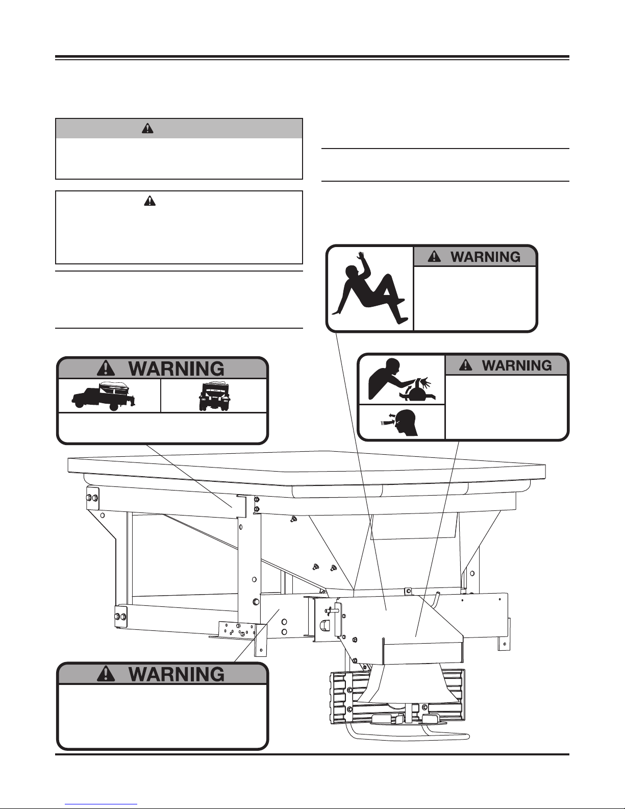
WARNING/CAUTION LABELS
Please become familiar with the Warning and Caution
labels on the spreader.
NOTE: If labels are missing or cannot be read, see
your sales outlet.
NO STEP
• Slippery Surface When Wet.
• May Cause Severe Injury
D6545
ROTATING PARTS AND FLYING OBJECTS CAN CAUSE INJURY OR DEATH
• Keep hands, arms, feet and loose clothing away
• Shut o power ans stop engine before servicing
• Read owners manual before operating.
• Keep bystanders at least 60 ft away.
D6544
• Read Owner’s Manual for Installation Instructions.
• Secure spreader to truck with ratchet straps.
• Anchor spreader securely to truck body with bolt kit provided to
prevent slipping or sliding.
• Routinely check straps and handware to make sure they are secure.
Lit. No. 43573/43583/43593, Rev. 01 3 August 15, 2013
D6548
Page 4
SAFETY INFORMATION
• DO NOT REMOVE SPREADER WITH MATERIAL IN HOPPER
• FASTEN SPREADER DOWN WITH APPROVED RATCHET
STRAPS AND BOLT KIT
• REAR FRAME LOCATOR BARS MUST BE IN PLACE BEFORE
OPERATING VEHICLE
DANGER
ROTATING AUGER CAN CAUSE
SERIOUS INJURY OR DEATH
• Keep arms, hands, and loose clothing
away from auger.
• Shut o control and unplug spreader
before servicing.
D6547
D6335
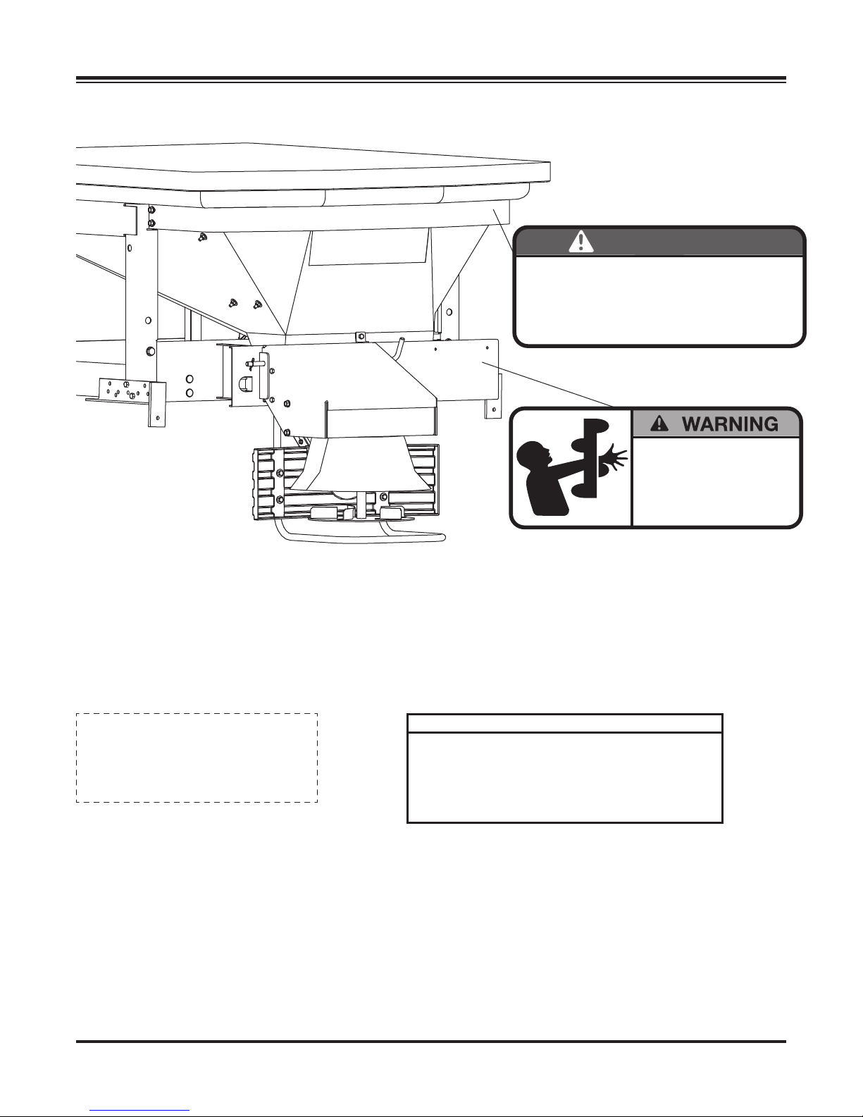
SERIAL NUMBER LABEL
Code Defi nition
MODEL NO.
0.5 cu yd
Lit. No. 43573/43583/43593, Rev. 01 4 August 15, 2013
SERIAL NO.
MMYYLL####PPPPP
MM 2-Digit Month
YY 2-Digit Year
LL 2-Digit Location Code
#### 4-Digit Sequential Number
PPPPP 5-Digit Assembly PN
Page 5
SAFETY INFORMATION
SAFETY PRECAUTIONS
Improper installation and operation could cause
personal injury and/or equipment and property damage.
Read and understand labels and the Owner's Manual
before installing, operating or making adjustments.
WARNING
• Driver to keep bystanders minimum of
25 feet away from operating spreader.
• Before working with the spreader, secure all
loose-fi tting clothing and unrestrained hair.
• Before operating the spreader, verify all
safety guards are in place.
• Before servicing the spreader, wait for
conveyor and spinner to stop.
• Do not climb into or ride on spreader.
WARNING
Overloading could result in an accident or
damage. Do not exceed GVWR or GAWR
ratings as found on the driver-side door
cornerpost of the vehicle. See Loading
Section to determine maximum volumes of
spreading material.
WARNING
Do not install the control for this product in
the deployment path of an air bag. Refer to
vehicle manufacturer's manual for air bag
deployment area(s).
CAUTION
During the hopper spreader installation
we recommend the addition of an OSHA
compliant Backup Alarm. This alarm is
required for OSHA governed employers.
CAUTION
• Do not operate a spreader in need of
maintenance.
• Before operating the spreader, reassemble
any parts or hardware removed for cleaning
or adjusting.
• Before operating the spreader, remove
materials such as cleaning rags, brushes,
and hand tools from the spreader.
• While operating the spreader, use auxiliary
warning lights, except when prohibited by law.
CAUTION
Disconnect electric and/or hydraulic power
and tag out if required before servicing or
performing maintenance.
CAUTION
DO NOT leave unused material in hopper.
Material can freeze or solidify, causing unit to
not work properly. Empty and clean after each
use.
NOTE: Lubricate grease fi ttings after each use.
Use a good quality multipurpose grease.
PERSONAL SAFETY
• Remove ignition key and put the vehicle in park or
in gear to prevent others from starting the vehicle
during installation or service.
• Wear only snug-fi tting clothing while working on
your vehicle or spreader.
• Do not wear jewelry or a necktie, and secure long
hair.
• Wear safety goggles to protect your eyes from
battery acid, gasoline, dirt and dust.
• Avoid touching hot surfaces such as the engine,
radiator, hoses and exhaust pipes.
• Always have a fi re extinguisher rated BC handy,
for fl ammable liquids and electrical fi res.
Lit. No. 43573/43583/43593, Rev. 01 5 August 15, 2013
Page 6
SAFETY INFORMATION
CELL PHONES
A driver's fi rst responsibility is the safe operation of
the vehicle. The most important thing you can do
to prevent a crash is to avoid distractions and pay
attention to the road. Wait until it is safe to operate
Mobile Communication Equipment such as cell
phones, text messaging devices, pagers or two-way
radios.
VENTILATION
WARNING
Vehicle exhaust contains lethal fumes.
Breathing these fumes, even in low
concentrations, can cause death. Never
operate a vehicle in an enclosed area without
venting exhaust to the outside.
BATTERY SAFETY
CAUTION
Batteries normally produce explosive gases
which can cause personal injury. Therefore,
do not allow fl ames, sparks or lit tobacco
to come near the battery. When charging or
working near a battery, always cover your
face and protect your eyes, and also provide
ventilation.
• Batteries contain sulfuric acid which burns
skin, eyes and clothing.
• Disconnect the battery before removing or
replacing any electrical components.
Lit. No. 43573/43583/43593, Rev. 01 6 August 15, 2013
Page 7
LOADING
These instructions cover vehicles which have been
recommended for carrying the hopper spreader.
Please see your local dealer for proper vehicle
applications.
WARNING
Overloading could result in an accident or
damage. Do not exceed GVWR or GAWR as
found on the driver-side cornerpost of vehicle.
MATERIAL WEIGHTS
CAUTION
Read and adhere to manufacturer's
ice-control material package labeling
including Material Safety Data Sheet
requirements.
CERTIFICATION
WARNING
New untitled vehicle installation of a spreader
requires National Highway Traffi c Safety
Administration altered vehicle certifi cation
labeling. Installer to verify that struck load of
snow or ice control material does not exceed
GVWR or GAWR rating label and complies
with FMVSS.
Lit. No. 43573/43583/43593, Rev. 01 7 August 15, 2013
Page 8
LOADING
DETERMINING VEHICLE PAYLOAD
WARNING
Overloading could result in an accident or
damage. Do not exceed GVWR or GAWR
ratings as found on the driver-side door
cornerpost of the vehicle. See Loading
Section to determine maximum volumes of
spreading material.
1. Install the hopper spreader and optional
equipment according to the instructions.
2. Install or attach any other equipment that will be
on the vehicle while the hopper spreader will be in
use (step bumper, trailer hitch, snowplows, etc.).
Fill gas tanks.
3. Obtain the Gross Vehicle Weight Rating (GVWR),
Front Gross Axle Weight Rating (FGAWR) and
Rear Gross Axle Weight Rating (RGAWR) from
the certifi cation label located inside the driver-side
door jamb or door.
7. Compare the maximum volume to determine the
maximum height of the material in the hopper
spreader.
8. Fill the hopper with the material to the calculated
height. Reweigh the vehicle with occupants
and verify the GVW, Front Gross Axle Weight
and Rear Gross Axle Weight are less than the
vehicle's ratings.
9. Repeat Steps 7 and 8 for each type of material.
WARNING
Do not overload vehicle. Use chart below
to calculate weight of material. Weights of
material are an average for dry materials.
CAUTION
Never use wet materials or materials with
foreign debris with any of these spreaders.
These units are designed to handle dry, clean,
free fl owing material.
4. With the occupants in the truck for normal hopper
spreader operation, weigh the vehicle to obtain
gross vehicle weight (GVW).
5. Subtract the GVW from the GVWR to determine
the available material payload.
6. Obtain the weight per cubic yard (lb/cu yd) of
the desired material. Divide the weight into the
payload to determine the maximum volume of
material that can be carried.
Material
Rock Salt – Dry
Sand/Salt Mix – Dry
Density
(lb/ft3)
80–90
95–120
Lit. No. 43573/43583/43593, Rev. 01 8 August 15, 2013
Page 9
MOUNTING THE SPREADER
MOUNTING SPREADER
NOTE: Periodically throughout the snow and ice
control season, verify mounting devices are secure.
WARNING
Spreader shall be bolted to vehicle frame.
Do not rely on the tie-down chains or straps
alone to hold spreader in vehicle.
CAUTION
Before lifting, verify hopper is empty of
material. The lifting device must be able to
support the spreader's weight as shown in
the spreader specifi cations table.
1. Remove the tailgate from the pickup bed.
2. Load the spreader onto the truck bed.
3. Mount the chute to the defl ector using the supplied
hardware kit.
4. Mount the chute/defl ector assembly to the spinner
assembly with supplied hardware to form the drive
assembly.
5. Mount the drive assembly to the spreader with a
bent pin and secure with a hair pin cotter.
6. Slide the spreader forward until the defl ector/chute
assembly makes contact with the vehicle. Then,
slide spreader back approximately 1" to allow
proper clearance.
CAUTION
Before drilling holes, check to be sure that no
vehicle wiring or other components could be
damaged.
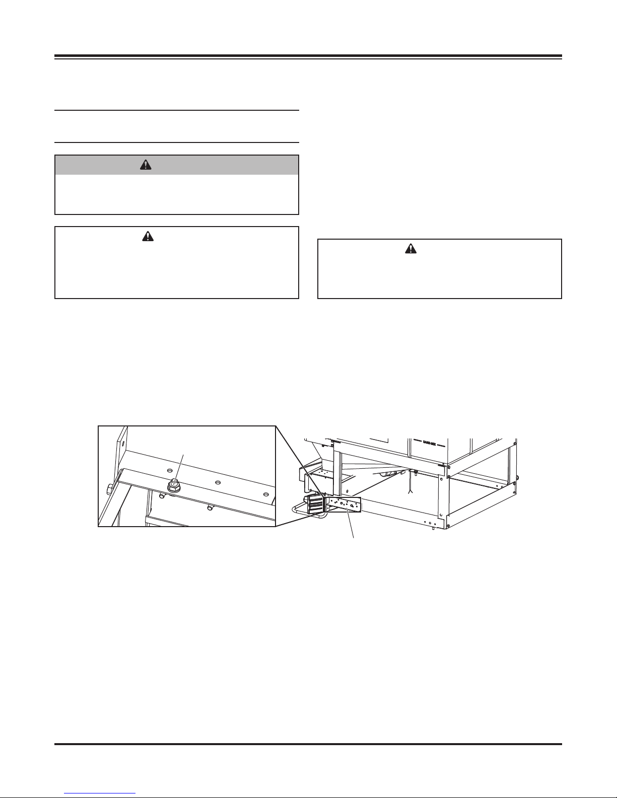
7. Install stop bars using supplied hole patterns (see
illustration below). To achieve the best position,
you may need to drill additional holes in the
bracket in order to properly position the spreader.
If there are interferences, relocate the holes,
making sure there are at least two forward and
two rearward of the front to back centerline.
Through floor/bed
mounting fasteners
Adjustable Stop Bracket
Lit. No. 43573/43583/43593, Rev. 01 9 August 15, 2013
Page 10
MOUNTING THE SPREADER
8. Once the spreader is positioned front to back,
center it left to right. Looking at the inside front
and rear corner of the lower frame area, you will
notice four holes in the bottom of the frame. Using
a paint pen or similar marking device, mark hole
locations.
CAUTION
Before drilling holes, check to be sure that no
vehicle wiring or other components could be
damaged.
9. Drill holes at the marked locations.
10. Install and tighten all four cap screws.
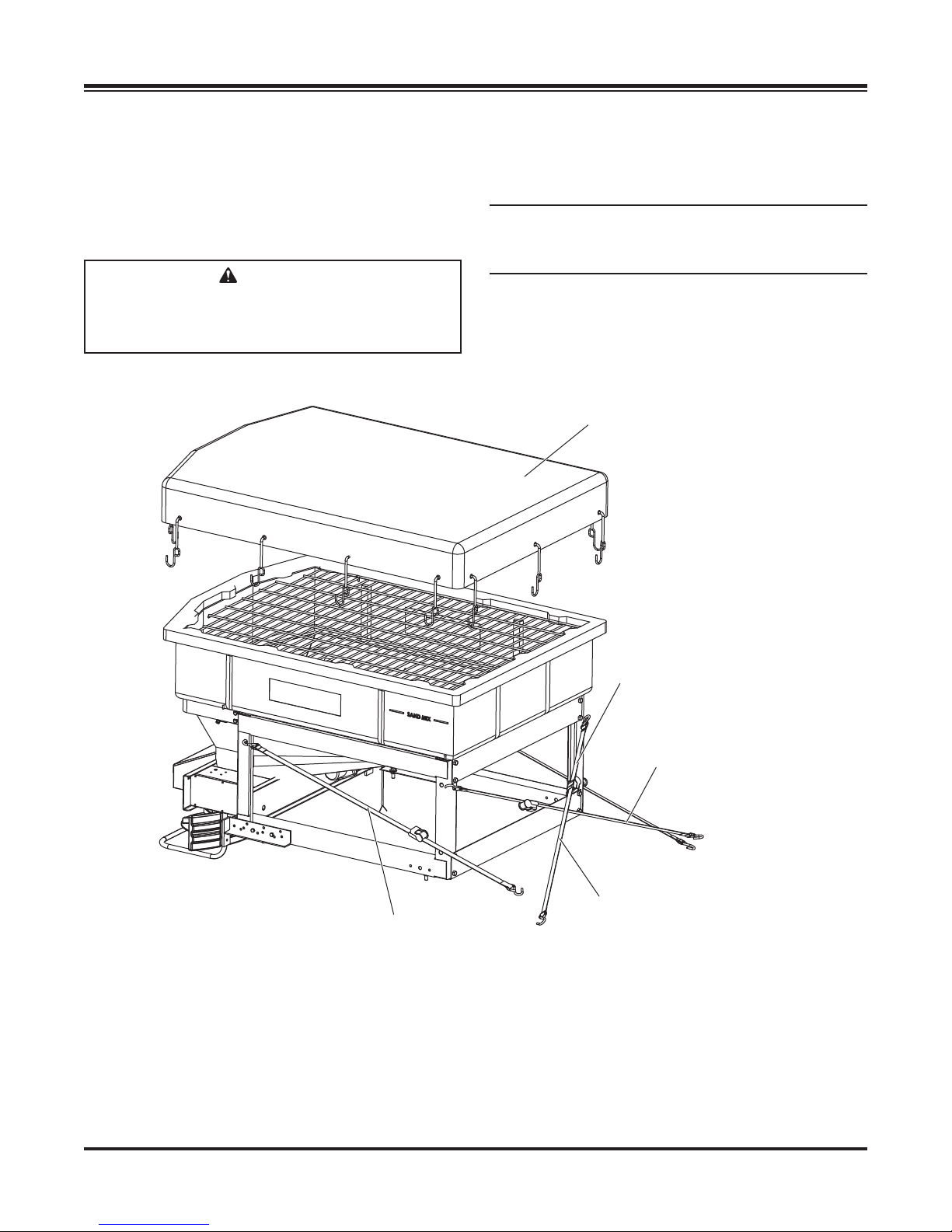
11. Install the four ratchet straps as shown below.
NOTE: It is important for safety that this strapping
method be used as the standard mounting
procedure.
12. Connect the spreader power cord to vehicle
main power plug mounted at the rear of the
vehicle (refer to installation instructions for wiring
instructions).
Tarp Kit
Strap from rear
of vehicle to front
corner (both sides)
Cross right upper to
left lower
Cross left upper to
right lower
Ratchet Strap
Lit. No. 43573/43583/43593, Rev. 01 10 August 15, 2013
Page 11
WIRING AND HARNESS INSTRUCTIONS
WIRING INSTRUCTIONS
1. Take the harness assembly and route from the
rear of the vehicle to the front. Route the harness
along the frame and attach to the frame holes and
frame supports.
It is not recommended to attach to fuel or brake
lines for obvious reasons. Do not route close
to exhaust system or engine. Even though the
hopper spreader uses high temperature wiring, it
still could melt under extreme heat and short the
spreader electrical system, as well as the vehicle
electrical system.
2. Mount rear plug on bumper using supplied
fasteners. Locate plug towards the center of the
bumper to reduce the amount of debris the tires
will throw to the rear.
NOTE: Apply a small amount of dielectric grease
to the plug. Try to mount plug facing upward to
help keep plugs tightly sealed.
3. Secure harness from the rear to the front using
heavy duty cable ties or frame clips along the
frame, and lighter duty cable ties everywhere else.
CAUTION
Before drilling holes, check to be sure that no
vehicle wiring or other components could be
damaged.
5. Connect power leads to the battery: Red
POSITIVE (+), Black NEGATIVE (–). Always
connect to the primary battery if using a dual
battery system. Secure loose loom to any other
large or medium vehicle harness with medium
duty cable ties to secure wiring harness.
NOTE: If adding an inline fuse, use a 60 amp slow
blow (time delay) or a 60 amp relay.
Vehicle Control Harness Installation
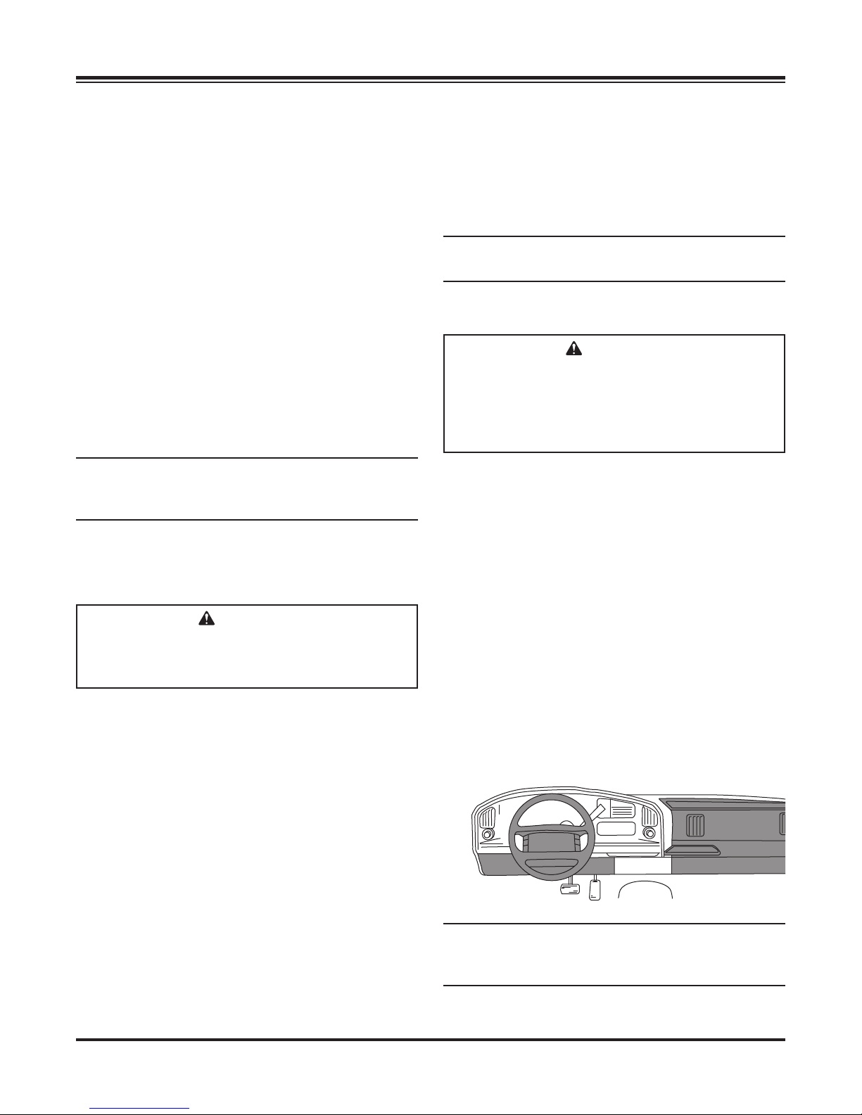
CAUTION
Do not alter, modify or install additional
components in shaded areas shown below.
Failure to comply may interfere with airbag
deployment or cause injury to operator in an
accident.
When choosing a location for your control, it should
be mounted in easy reach of the vehicle operator and
not restricting access to vehicle controls or vehicle
instrumentation. Do not mount the control in areas
prohibited by the vehicle manufacturer for crash
worthiness. See the vehicle's body builder's book,
owner's manual or service manual for details. The
shaded areas in the illustration below show the most
commonly restricted areas.
1. Install control bracket to control using nylon and
steel washers and cap screws.
4. Layout harness portion that connects to the
battery along the re wall and fender well. Do
not connect power leads to battery yet. Drill a
3/4" hole in the fi re wall or use existing access
hole for the control portion of the harness. Route
the connector and harness through the hole.
Be sure to check the area on the other side of
the fi re wall to make sure you are not going to
drill into the vehicle harness or a control module.
Generally, either side of the steering wheel is a
good location to place the hole.
Lit. No. 43573/43583/43593, Rev. 01 11 August 15, 2013
2. Connect the harness to the back of the control
and mount to a suitable location. Cable tie
loose control harness and move to the engine
compartment. Do not mount close to any heater
vents.
NOTE: You may want to contact customer support
before mounting control if you prefer not to drill
holes into the dashboard.
Page 12

WIRING AND HARNESS INSTRUCTIONS
3. Push the ON/OFF switch on the control to check
for power. After power has been confi rmed,
push the ON/OFF switch again to turn OFF. The
electrical portion of the installation is complete.
NOTE: Use dielectric grease on all electrical
connections.
HARNESS DUST COVER
Install the dust cover as shown.
NOTE: In the off season, remove control and
put in a cool, dry place. The interior summer
temperatures could damage circuit board and
void warranty.
NOTE: Do not modify harness length. Any
modifi cations will void warranty.
• All external connections must have dielectric
grease.
• Read lead labels before attaching to power source
or ground.
• No other devices may be spliced into wiring
harness.
• Any repairs to wiring harness must be done with
heat shrink butt connectors.
• If inline fuse is installed, use a 60 amp maxi fuse or
circuit breaker.
Lit. No. 43573/43583/43593, Rev. 01 12 August 15, 2013
Page 13
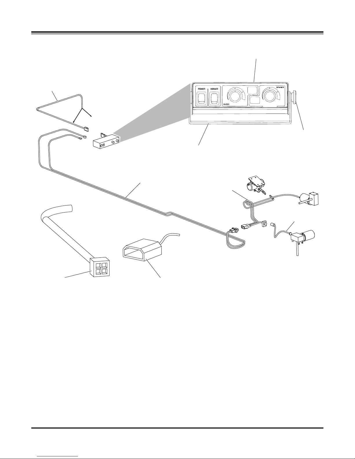
Control Power Cable
HARNESS WIRING DIAGRAM
Spreader Control
1/4" x 1/2"
Cap Screw
Control Mounting Bracket
Connector
Adapter
Vehicle Harness
Dust Cover
Spreader
Harness
Power Cable
Lit. No. 43573/43583/43593, Rev. 01 13 August 15, 2013
Page 14
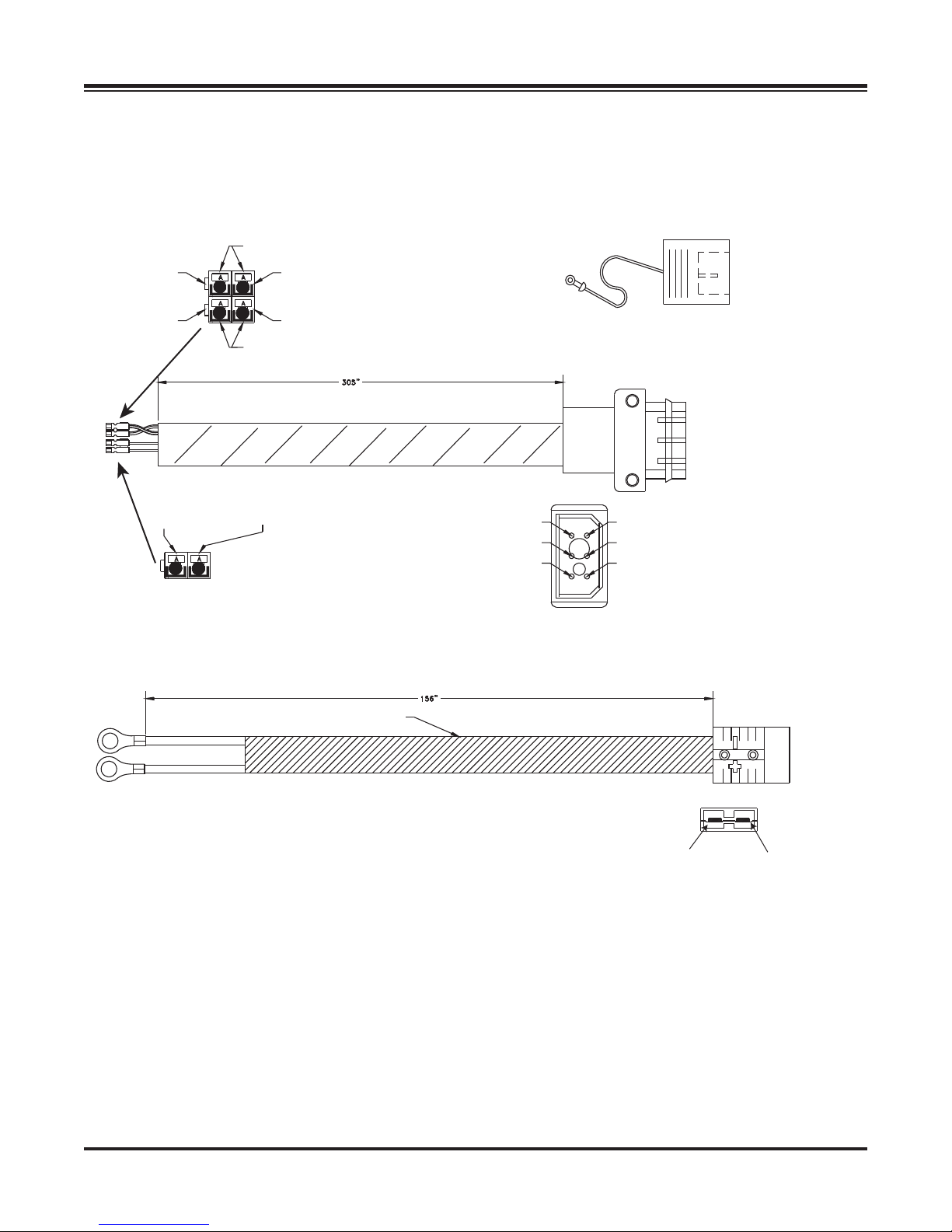
Vehicle Harness
HARNESS DIAGRAM
End View
Red
White 10 GA
Spinner +
Black 10 GA
Spinner –
Blue 12 GA
Vibrator –
Black
Orange 10 GA
Vibrator –
Control Power Cable
Red 10 GA
Auger +
Green 10 GA
Auger –
Vibrator + 12 GA Orange
Spinner + 10 GA White
Auger + 10 GA Red
Hot
Circuit
Mold Cap
Spinner – 10 GA Black
Auger – 10 GA Green
Vibrator – 12 GA Blue
Grd
Circuit
3/8" Terminal w/Heat Shrink
Black
Red
124" Tubing
Red to
Positive +
Front View
Black to
Negative –
Lit. No. 43573/43583/43593, Rev. 01 14 August 15, 2013
Page 15
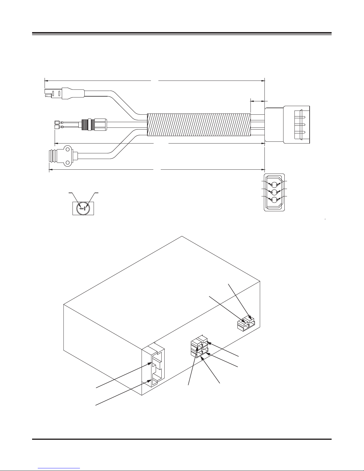
Spreader Harness
Vibrator Plug
Male
Female
Black
Red
Spinner
HARNESS DIAGRAM
42
5”
19 1/2”
Auger Motor
65 1/4”
47
Negative
Control
Load
View
Positive
Vibrator
Red Positive (+)
Vibrator
Black Negative (-)
Vibrator Positive
Auger Positive
Spinner Positive
Vibrator Negative
Auger Negative
Spinner Negative
Load
View
Black
Negative (-)
Red
Pos iti ve (+)
Lit. No. 43573/43583/43593, Rev. 01 15 August 15, 2013
Spinner
Black Negative (-)
Auger
Black Negative (-)
Auger
Red Positive (+)
Spinner
Red Positive (+)
Page 16
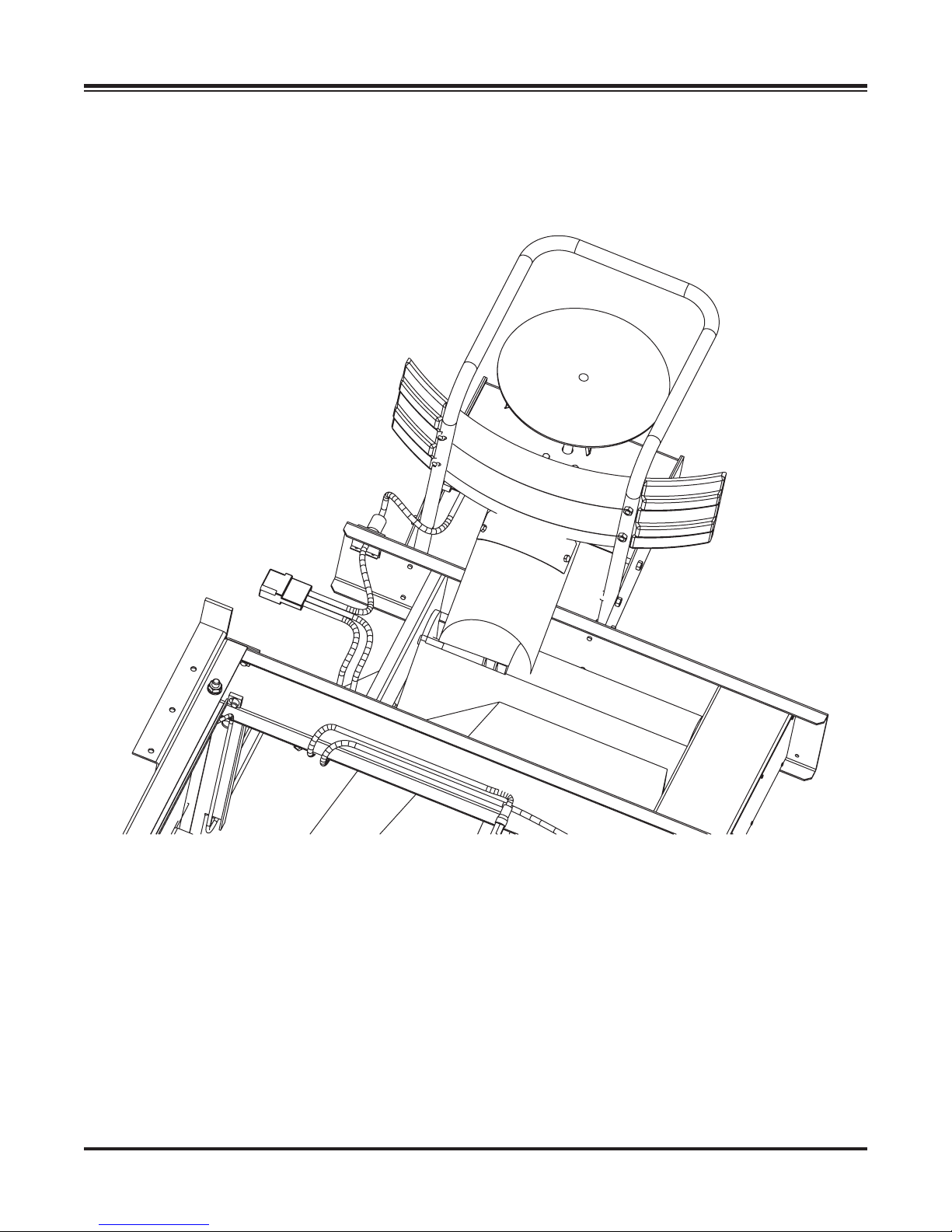
ELECTRICAL ROUTING
Spinner
Main Input
Auger and Vibrator (not supplied on drawing)
Lit. No. 43573/43583/43593, Rev. 01 16 August 15, 2013
Page 17

FINAL ADJUSTMENTS
FINAL CHECKLIST
Verify dielectric grease is applied to all electrical
connections.
Verify wire harnesses and battery cables are
properly secured away from hot or moving parts.
Verify vehicle battery cable has suffi cient ground
clearance when spreader is removed from truck.
Lit. No. 43573/43583/43593, Rev. 01 17 August 15, 2013
Page 18

Fisher Engineering
50 Gordon Drive
Rockland, ME 04841-2139
www.fi sherplows.com
A DIVISION OF FISHER, LLC
Fisher Engineering reserves the right under its product improvement policy to change construction or design details and furnish equipment
when so altered without reference to illustrations or specifi cations used. Fisher Engineering or the vehicle manufacturer may require or
recommend optional equipment for spreaders. Do not exceed vehicle ratings with a spreader. Fisher Engineering offers a limited warranty for
all spreaders and accessories. See separately printed page for this important information. The following are registered (®) or unregistered (™)
trademarks of Douglas Dynamics, LLC: FISHER®, POLY-CASTER™ LT.
Lit. No. 43583, Rev. 01 August 15, 2013
Printed in U.S.A.
 Loading...