

Fisher FM Hazardous Area Approvals for Fisher i2P-100 Electro-Pneumatic Transducer Manuals & Guides
Instruction Manual Supplement
D104193X012
i2P-100 Transducer - FM
July 2018
FM Hazardous Area Approvals
™
Fisher
Hazardous Area Classifications and Special Instructions for “Safe Use” and
Installation in Hazardous Locations
Certain nameplates may carry more than one approval, and each approval may have unique installation/wiring
requirements and/or conditions of “safe use”. These special instructions for “safe use” are in addition to, and may
override, the standard installation procedures. Special instructions are listed by approval.
Note
This information supplements the nameplate markings affixed to the product and the i2P-100 instruction manual
(D103198X012
Always refer to the nameplate itself to identify the appropriate certification.
i2P-100 Electro‐Pneumatic Transducer
), available from your Emerson sales office or Local Business Partner, or at www.Fisher.com.
WARNING
Failure to follow these conditions of “safe use” could result in personal injury or property damage from fire or explosion,
and area re‐classification.
Special Conditions of Use
Intrinsically Safe, Explosion-proof, Type n, Non‐incendive, Dust‐Ignition proof
1. When product is used with natural gas as the pneumatic medium, the maximum working pressure of the natural
gas supply is limited to 50 psi.
2. When product is used with natural gas as the pneumatic medium the product shall be provided with the proper
remote venting, as described in the i2P-100 instruction manual (D103198X012).
3. The apparatus enclosure contains aluminum and is considered to constitute a potential risk of ignition by impact or
friction. Care must be taken into account during installation and use to prevent impact or friction.
Refer to table 1 for additional information.
www.Fisher.com
i2P-100 Transducer - FM
July 2018
Instruction Manual Supplement
Table 1. Additional Approval Information
Certification Body Certification Obtained Entity Rating Temperature Code
FM
IS Intrinsically Safe
Class I, II, III Division 1 GP A, B,C,D,E,F,G
per drawing GE07470 (see figure 1)
Class I Zone 0 AEx ia IIC T3/T4/T5
per drawing GE07470 (see figure 1)
XP Explosion Proof
Class I, Division 1, GP A,B,C,D T5/T6
Class I Zone 1 AEx d IIC T5/T6
NI Non-incendive
Class I, Division 2, GP A,B,C,D T5/T6
Type n
Class I, Zone 2 AExnC IIC T5/T6
DIP Dust-ignition proof
Class II, III Division 1, GP E,F,G T5/T6
S Suitable for Use
Class II, III Division 2, GP F,G T5/T6
Vmax = 30 VDC
Imax = 100 mA
Pi = 1.0 W
Ci = 0 uF
Li = 0 uH
- - -
T3 (Tamb ≤ 85°C)
T4 (Tamb ≤ 81°C)
T5 (Tamb ≤ 46°C)
T5 (Tamb ≤ 85°C)
T6 (Tamb ≤ 75°C)
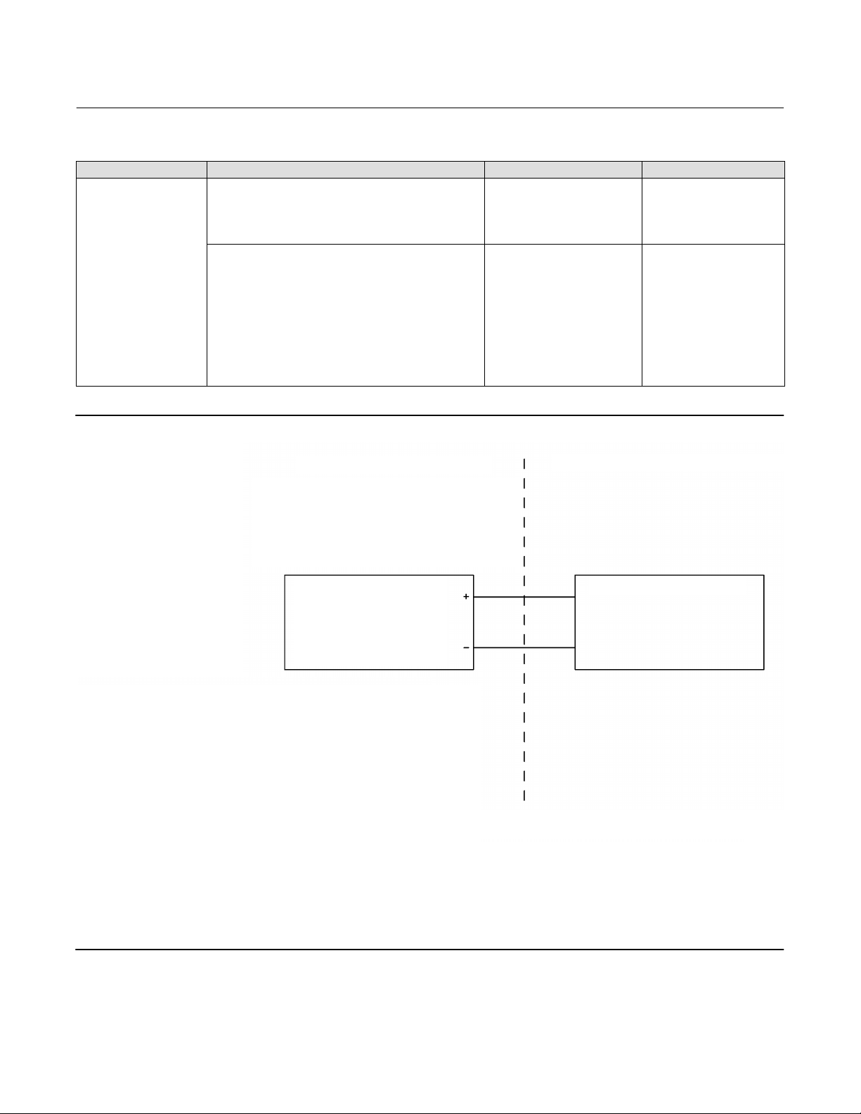
Figure 1. FM Loop Schematic (Drawing GE07470)
D104193X012
HAZARDOUS LOCATION
INTRINSIC SAFETY
CLASS I, II, III, DIV 1, GROUPS A,B,C,D,E,F,G
CLASS I, ZONE 0 AEx ia IIC
NON-INCENDIVE
CLASS I, DIV 2, GROUPS A,B,C,D
FISHER TYPE: i2P-100
Vmax = 30 Vdc
Imax = 100 mA
Ci = 0 nF
Li = 0 mH
Pi = 1.0 W
NOTES:
1. THE INSTALLATION MUST BE IN ACCORDANCE WITH
THE NATIONAL ELECTRIC CODE (NEC), NFPA 70, ARTICLE
504 AND ANSI/ISA RP12.6 OR ARTICLE 505.
2. CLASS 1, DIV 2 APPLICATIONS MUST BE INSTALLED AS SPECIFIED
IN NEC ARTICLE 501-4(B). EQUIPMENT AND FIELD WIRING IS
NON-INCENDIVE WHEN CONNECTED TO APPROVED BARRIERS WITH
ENTITY PARAMETERS.
3. LOOPS MUST BE CONNECTED ACCORDING TO THE BARRIER
MANUFACTURER'S INSTRUCTIONS.
4. MAXIMUM SAFE AREA VOLTAGE SHOULD NOT EXCEED 250 Vrms.
5. RESISTANCE BETWEEN BARRIER GROUND AND EARTH GROUND
MUST BE LESS THAN ONE OHM.
6. NORMAL OPERATINGI CONDITIONS 30 Vdc 20 mADC.
7. FOR ENTITY INSTALLATION (I.S. AND N.I.):
Vmax > Voc, or Vt Ci + Ccable < Ca
Imax > Isc, or It Li + Lcable < La
Pi > Po, or Pt
GE07470_B
NON-HAZARDOUS LOCATION
FM APPROVED BARRIER
WARNING:
THE APPARATUS ENCLOSURE CONTAINS ALUMINUM AND
IS CONSIDERED TO CONSTITUTE A POTENTIAL RISK OF
IGNTION BY IMPACT OR FRICTION. AVOID IMPACT AND
FRICTION DURING INSTALLATION AND USE TO PREVENT
RISK OF IGNITION.
2

Instruction Manual Supplement
D104193X012
i2P-100 Transducer - FM
July 2018
Neither Emerson, Emerson Automation Solutions, nor any of their affiliated entities assumes responsibility for the selection, use or maintenance
of any product. Responsibility for proper selection, use, and maintenance of any product remains solely with the purchaser and end user.
Fisher is a mark owned by one of the companies in the Emerson Automation Solutions business unit of Emerson Electric Co. Emerson Automation Solutions,
Emerson, and the Emerson logo are trademarks and service marks of Emerson Electric Co. All other marks are the property of their respective owners.
The contents of this publication are presented for informational purposes only, and while every effort has been made to ensure their accuracy, they are not
to be construed as warranties or guarantees, express or implied, regarding the products or services described herein or their use or applicability. All sales are
governed by our terms and conditions, which are available upon request. We reserve the right to modify or improve the designs or specifications of such
products at any time without notice.
Emerson Automation Solutions
Marshalltown, Iowa 50158 USA
Sorocaba, 18087 Brazil
Cernay, 68700 France
Dubai, United Arab Emirates
Singapore 128461 Singapore
www.Fisher.com
E 2016, 2018 Fisher Controls International LLC. All rights reserved.
3
 Loading...