

Page 1

Instruction Manual
D104555X012
TBX-P Valve
August 2020
Fisher
™
TBX-P Steam Pressure Control Valve
Contents
Introduction 1.................................
Scope of Manual 1.............................
Description 3.................................
Educational Services 3.........................
Installation 4..................................
Maintenance 7.................................
Servicing 8...................................
Removal of Valve Bonnet and Trim 8.............
Valve Assembly 10............................
Parts Ordering 18...............................
Parts List 18...................................
Figure 1. Fisher TBX-P Steam Pressure Control Valve
X1715
Introduction
Scope of Manual
This instruction manual includes installation, maintenance, and operation information for the Fisher TBX control valve.
Refer to separate instruction manuals for instructions covering the actuator and accessories.
Do not install, operate, or maintain a TBX-P valve without being fully trained and qualified in valve,
actuator, and accessory installation, operation, and maintenance. To avoid personal injury or property
damage, it is important to carefully read, understand, and follow all the contents of this manual, including
all safety cautions and warnings. If you have any questions about these instructions, contact your Emerson
sales office before proceeding.
www.Fisher.com
Page 2
TBX-P Valve
August 2020
Instruction Manual
Table 1. Specifications for Standard Designs (Physical Specifications)
End Connection Sizes
Valve Inlet: NPS 4 through NPS 24
Valve Outlet: NPS 8 through NPS 60
End Connection Types
J ASME Buttweld (all sizes)
J ASME Raised Face Flanges (all sizes)
J ASME Ring Type Joint Flanges (all sizes)
(1)
Bonnet Bolting
J SA193 Grade B7
J SA193 Grade B16
J N07718
Seat Ring
Welded Seat Ring (flow up only)
J Carbon Steel with Alloy 6
J 2.25Cr1 Mo with Alloy 6
J 9Cr1 MoV with Alloy 6
J 9Cr2 WV with Alloy 6
Valve Configuration
Angle Pattern (flow up or flow down)
Valve Body Ratings
(2)(4)
ASME: CL150 - CL2500
Bolted Seat Ring
J 2.25Cr1 Mo with Alloy 6 and N07718 Bolting
J N06625 with Alloy 6 and N07718 Bolting
J N07718 with Alloy 6 and N07718 Bolting
Plug:
Control Plug
SA182 Grade F22 (2.25Cr1 Mo) with Alloy 6
Bonnet Type
Bolted
Guiding Surfaces
SA182 Grade F91 (9Cr1 MoV) with Alloy 6
Guiding Surfaces
Shutoff Classifications per ANSI/FCI 70‐2 and IEC
60534‐4
Standard: Class V
Optional: Class IV
Flow Characteristics
(3)
Whisper Trim™ III: Linear
WhisperFlo™ (flow up only): Linear
Stem
J SA479 Type S20910
J N07718
Cage:
Control Cage
J 2.25Cr1 Mo Nitrided
J 9Cr1 MoV Nitrided
J S41000 Cage with 2.25Cr1 Mo Retainer
J S41000 Cage with 9Cr1 MoV Retainer
Lower Cage (flow down only)
Flow Direction
Whisper Trim III: Flow up or down
WhisperFlo: Flow up
Construction Materials
Body/Bonnet
J SA105 Carbon Steel
J SA182 Grade F22 (2.25Cr1 Mo)
J SA182 Grade F91 (9Cr1 MoV)
J SA182 Grade F92 (Cr2 WV)
1. Consult your Emerson sales office for additional options.
2. Not all valve sizes are available in all valve body ratings.
3. Contact your Emerson sales office for other flow characteristics.
4. Intermediate classes above CL2500 available upon request. Consult your Emerson sales office for additional information. PN pressure ratings available per pressure requirements of
EN1092-1.
5. WhisperFlo constructions only.
J 2.25Cr1 Mo Nitrided
J 9Cr1 Mo-V Nitrided
Piston Rings
Alloy 6B with N07750 Expander
Bore Seal
N07718
Gaskets
Bonnet: N07718/Graphite
All Others: N06600/Graphite
Packing
Graphite/Flexible Graphite
D104555X012
(5)
(5)
2
Page 3

Instruction Manual
D104555X012
TBX-P Valve
August 2020
Educational Services
For information on available courses for the Fisher TBX-P steam pressure control valve, as well as a variety of other
products, contact:
Emerson Automation Solutions
Educational Services - Registration
Phone: 1-641-754-3771 or 1-800-338-8158
E-mail: [email protected]
emerson.com/fishervalvetraining
Description
TBX-P steam pressure control valves (see figure 1) are balanced-plug angle valves that are custom built for each
application. Typical installations include steam pressure control, vent to atmosphere, auxiliary steam and other
applications requiring dependable and accurate control of steam pressure.
The TBX-P steam pressure control valve (see figure 1) is designed to handle the most severe applications in today's
cycling power plants as well as provide precise pressure control for process applications. The TBX-P incorporates more
than 30 years of steam pressure control experience and product development. The valve body is designed with the
latest finite element analysis (FEA) and computational fluid dynamics (CFD) tools to optimize performance and
reliability for demanding steam systems.
The TBX-P is a flow up or flow down design providing the ultimate combination of performance and maintainability.
The flow down TBX-P incorporates Emerson's low noise Whisper Trim III technology. The flow up TBX-P incorporates
the same Whisper Trim III technology as the flow down design, but can also be outfitted with WhisperFlo Trim
technology.
3
Page 4
TBX-P Valve
August 2020
Instruction Manual
D104555X012
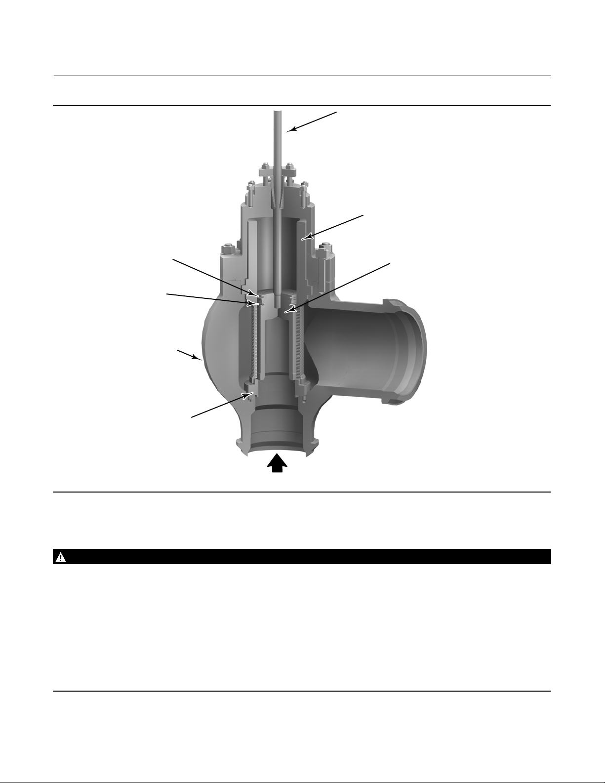
Figure 2. Typical Fisher TBX-P
PISTON RING
BORE SEAL
BODY
STEM
CAGE
PLUG
SEAT RING
FLOW
Installation
WARNING
Always wear protective gloves, clothing, and eyewear when performing any installation operations to avoid personal
injury.
Personal injury or equipment damage caused by sudden release of pressure may result if the TBX-P valve is installed where
service conditions could exceed the limits of the pressure rating noted on the nameplate. To avoid such injury or damage,
provide a relief valve for over pressure protection as required by government or accepted industry codes and good
engineering practices.
Check with your process or safety engineer for any additional measures that must be taken to protect against process
media.
If installing into an existing application, also refer to the WARNING at the beginning of the Maintenance section in this
instruction manual.
4
Page 5

Instruction Manual
D104555X012
TBX-P Valve
August 2020
CAUTION
This valve is intended for a specific range of service conditions (see table 1). Applying different conditions to the valve could
result in parts damage, malfunction of the valve, or loss of control of the process. Do not expose this valve to service
conditions or variables other than those for which this valve is intended. If you are not sure what these conditions are, you
should contact Emerson for more complete specifications. Provide the product serial number (shown on the nameplate)
and all other pertinent information.
Check that the TBX-P valve is properly orientated with respect to the flow direction of the valve (either flow up or flow
down). Incorrect installation can result in damage to the valve and poor performance.
1. Before installation, all piping upstream of the valve must be blown clean so that no loose materials such as welding
slag, dirt or other foreign matter, are left in the pipe. Use care to keep foreign matter out of the line openings while
preparing the valve installation.
2. If possible, before fitting in the line, connect the actuator to a temporary air supply and operate to verify
positioning. Disconnect the instrument lines (if applicable).
WARNING
Do not lift the valve by its actuator yoke. Lifting lugs attached to the actuator must not be used to lift the complete
valve assembly unless clearly marked as being rated to support the complete valve assembly weight. Personal injury or
damage to equipment could occur if the valve is improperly lifted into place.
All lifting and rigging must be completed in accordance with federal/national/provincial, state and local regulations
and applicable lifting and rigging equipment standards. Only personnel trained in proper lifting and rigging practices
shall perform valve/actuator assembly lifting, rigging and installation. Because each lift will be unique, the method of
lifting the valve assembly, the correct location for attaching and lifting the valve assembly, and what the valve
assembly will do when lifted shall be considered for each lift.
Lifting and rigging equipment used to lift, install or remove a valve assembly or component must be properly selected
and sized for the weight and configuration of the valve assembly or component being lifted. The weight of the
complete valve assembly, including attached accessories, must be taken in consideration for this purpose. The lifting
and rigging equipment must be properly maintained and inspected for damage before each use.
Lifting lugs or other lifting equipment attached to the valve or actuator must never be used to lift or support the
weight of attached piping.
If the TBX-P is equipped with buttweld ends, the valve body must be supported using a lifting sling or other method that
does not place a load or force onto the finished surface of the buttweld ends. The TBX-P does not have a stable resting
condition. The valve inlet and outlet must be fully supported until fully welded (buttweld end connections) or bolted
(flanged end connections) into the piping.
CAUTION
Care must be taken when lifting the valve/actuator assembly to ensure all accessories and tubing are not damaged in
the process. Accessories and tubing may need to be removed prior to lifting to prevent damage and properly
reinstalled before use. Protect valve flange faces, butt weld ends, and other connection surfaces from damage during
lifting.
3. Arrange lifting slings, or other lifting and rigging equipment appropriate for the valve weight and configuration to
safely lift the valve to the pipe opening.
5
Page 6

TBX-P Valve
August 2020
Instruction Manual
D104555X012
WARNING
Do not expose the valve to undue stresses by installing it in bent pipes or flanges. Personal injury and equipment damage
could result from flange sealing failure due to improper installation.
4. Flanged Connections—Lubricate the flange connection bolts with a high temperature thread lubricant. Install flange
gaskets and connection bolts per accepted practices and tighten securely.
5. Welded Connections—Welding procedures should be in accordance with the applicable codes and the base
materials. For preheat, welding electrodes, and postweld heat treatment, refer to the applicable codes and
practices applicable for the specific facility. Materials are specified on the customer specification sheet. Emerson
recommends the valve be disassembled for welding, however if the valve inlet and outlet connections are to be
welded with the valve assembled, the valve plug should be maintained off the valve seat during all associated
operations. If the valve is to be welded by SMAW process, the valve must be disassembled for welding to ensure
that any weld slag is removed from the valve.
CAUTION
Depending on valve body materials used, post weld heat treating may be required. If so, damage to internal parts is
possible. In general, if post weld heat treating is to be performed, all trim parts should be removed. Contact your Emerson
sales office for additional information.
Pneumatic lines (where applicable) should be thoroughly blown clean with dry air before connection. Check electronic
lines for correct connection.
6. If foreign debris has been introduced into the valve or upstream piping during installation, it must be removed prior
to using the valve for the first time. A blowout or blowdown tool can be purchased to match the TBX-P valve and
facilitate piping blowdown without removal of the valve from the line. Contact your Emerson sales office for pricing
and availability of fixtures. Review Fisher instruction manuals, TBX-P Blowout Fixture (D103206X012
Blowdown Fixture (D103207X012
) prior to use.
) and Fisher
7. After cleanliness of the piping system has been assured, connect instrumentation and power supply to the TBX-P
valve actuator and associated equipment.
8. Monitor the TBX-P valve as the system is brought online. Some visible vapors may be seen while the lubricants are
heated. If you see any steam leaks after startup, follow isolation and disassembly procedures and disassemble the
valve and replace the gaskets (key 43). If the packing box leaks, tighten hex nuts (key 68). If leakage continues,
replace the packing (key 64). Be sure to properly isolate the TBX-P valve prior to disassembly of valve or packing.
WARNING
Personal injury could result from packing leakage. Valve packing was tightened prior to shipment; however, the packing
might require some readjustment to meet specific service conditions. Check with your process or safety engineer for any
additional measures that must be taken to protect against process media.
6
Page 7
Instruction Manual
D104555X012
TBX-P Valve
August 2020
Maintenance
It is recommended that diagnostic tests be performed on the valve 3 to 6 months prior to scheduled maintenance
shutdowns. Complete valve disassembly is recommended if tests performed on the valve indicate leakage, sticking, or
substandard operation. If diagnostics indicate normal valve operation, complete disassembly and inspection of the
TBX-P is recommended during every other regularly scheduled outage or after 24 to 36 months, whichever comes
first. Table 2 identifies the recommended inspection tips and diagnostics that can be performed with corresponding
repair and replacement information.
Table 2. Inspection Summary
Key Part Description Inspection Tips and Diagnostics Repair Replacement
1 Valve Body
6 Bonnet
21 Cage
22 Plug
23, 53 Stem and Stem Pin
24 Seat
25 Plug Retainer Inspect for excessive wear, galling, and other damage.
43, 75 All Gaskets
45 Piston Ring
46 Bore Seal Ring
63 Packing Box Ring Inspect for scoring, galling, and other damage. Replacement Only As needed
64 Packing Set
65 Packing Follower Inspect for scoring, galling, and other damage. Replacement Only As needed
66 Packing Flange Inspect for scoring, galling, and other damage. Replacement Only As needed
Inspect for erosion, thermal fatigue, and other
damage.
Inspect gasket surfaces for damage that could indicate
gasket leakage. Inspect packing box to ensure no
galling, scoring, or particulate is present.
Inspect cage bore for excessive wear, galling damage,
particulate damage, and flow passage damage or
clogging.
Inspect for seat erosion, excessive wear, galling
damage, and particulate damage, paying close
attention to the seating and guiding surfaces.
Inspect stem for dings, scoring, and galling. Inspect
valve stem connection for tightness.
Inspect for seat erosion, particulate damage, galling,
and proper bolt torque (if applicable, refer to table 3).
Every valve disassembly requires replacement of
gaskets.
Inspect for particulate buildup, scoring, and excessive
wear. Ensure piston ring is free to expand and contract
in the groove.
Inspect for excessive wear, galling, signs of leakage,
and other damage.
Every valve disassembly requires replacement of the
packing set.
Consult your local Emerson Service Center for a recommendation on
necessary weld repair or replacement if damage exists.
If damage exists consult your local Emerson Service Center for a
recommendation on necessary weld repair or replacement.
Consult your local Emerson Service
Center for a recommendation on
necessary repair or replacement if
damage exists.
Re-cutting/machining of seating
surfaces can be performed by your
local Emerson Service Center.
Valve stem connection can be
repaired by your local Emerson
Service Center.
Re-cutting/machining of seating
surfaces can be performed by your
local Emerson Service Center.
Repair can be performed by your
local Emerson Service Center.
Replacement Only Every valve disassembly
Replacement Only As needed
Replacement Only
Replacement Only Every valve disassembly
As needed for optimal
performance
As needed for optimal
performance
As needed
As needed to maintain proper
shutoff
As needed
Every 36 months for optimal
performance
7
Page 8

TBX-P Valve
August 2020
Instruction Manual
D104555X012
WARNING
Avoid personal injury or property damage from sudden release of process pressure or bursting of parts. Before performing
any maintenance operations:
D Do not remove the actuator from the valve while the valve is still pressurized.
D Always wear protective gloves, clothing, and eyewear when performing any maintenance operations to avoid personal
injury.
D Disconnect any operating lines providing air pressure, electric power, or a control signal to the actuator. Be sure the
actuator cannot suddenly open or close the valve.
D Use bypass valves or completely shut off the process to isolate the valve from process pressure. Relieve process pressure
from both sides of the valve. Drain the process media from both sides of the valve.
D Vent the power actuator loading pressure and relieve any actuator spring precompression.
D Use lock‐out procedures to be sure that the above measures stay in effect while you work on the equipment.
D The valve packing box may contain process fluids that are pressurized, even when the valve has been removed from the
pipeline. Process fluids may spray out under pressure when removing the packing hardware or packing rings, or when
loosening the packing box pipe plug.
D Check with your process or safety engineer for any additional measures that must be taken to protect against process
media.
Servicing
Shut off steam flow and vent all system pressure before breaking any pressure boundaries.
WARNING
Residual system pressure may be released during the following steps if the system was improperly isolated or vented.
Use extreme care to prevent personal injury while loosening any fasteners in the pressure boundary.
Removal of Valve Bonnet and Trim
1. Disconnect all external connections to the positioner and actuator and remove the actuator from the valve. Consult
the actuator manufacturer's documentation for assistance in actuator removal.
2. Loosen and remove the hex nuts (key 68) along with the packing follower (key 65). If possible, remove packing set
(key 64) from the packing box.
3. Loosen bonnet stud nuts (key 55) using an even pattern to avoid uneven expansion of the gaskets. Remove the
entire bonnet assembly (key 6), pulling evenly in line with the valve stem (key 23) centerline. Uneven bonnet
removal can result in galling or bending of the valve stem. If difficulty is encountered in removing the bonnet, check
the bonnet for alignment and straighten the bonnet before making further attempts to remove it from the valve
body.
8
Page 9

Instruction Manual
D104555X012
TBX-P Valve
August 2020
CAUTION
The bonnet must be handled with care while being removed from the body. Damage to the bonnet can result in gasket
leakage while the valve is in service.
Protect the bonnet by placing it on clean cloth or wood while the valve is disassembled.
4. Dislodge any remaining packing (key 64) from the packing box and discard. Remove the packing box ring (key 63)
from the bottom of the packing box. Inspect all parts: packing box, packing box ring (key 63), packing follower (key
65), valve stem (key 23), hex nuts (key 68) and studs (key 69) for signs of wear. Replace parts that are damaged or
show excessive wear.
5. Inspect the bonnet guiding surfaces and gasket mating surfaces. Light damage on the guiding surface may be
repaired with an emery cloth or other suitable material. Damage to the gasket mating surface may require bonnet
replacement to avoid leakage.
6. Remove the plug assembly (flow up and flow down: keys 22, 23, 25, and 53) as a single unit by lifting the valve stem
(key 23) with appropriate rigging and lifting equipment and pulling the assembly from the body cavity. The plug
assembly contains sensitive guiding and sealing surfaces on its outside diameter and care must be taken in its
handling. Protect the plug by placing it on clean cloth or wood while the valve is disassembled.
7. Flow Up Construction only: If the TBX-P has a magnetite catcher (key 79) and excess magnetite buildup is present,
remove the magnetite catcher located in the bore of the plug (key 22) by cutting the tackwelds at the base of the
part and unscrewing from the plug. Clean as necessary to remove magnetite buildup.
8. Remove the cage (key 21) from the valve body. Remove and discard two (2) cage gaskets (key 43). Reference
figures 9, 10, and 11 for guidance in performing this disassembly. The cage contains sensitive guiding surfaces on
its inside and outside diameter and care must be taken during handling. Protect the cage by placing it on clean cloth
or wood while the valve is disassembled.
9. ANSI/FCI 70-2 Class V constructions only: Clean and inspect the guiding and sealing surfaces of the plug assembly.
Inspect the piston ring (key 45) and Bore Seal ring (key 46) for signs of excess wear or damage and replace if
necessary. The piston ring is a two-piece design with an outer seal ring and an inner expander ring. The outer ring
diameter should be expanded beyond the diameter of the plug in its free state. It can be shifted within its groove to
inspect for uneven wear around its circumference. The piston ring should require some compression when
installing the plug into the cage. Lack of required compression indicates that the piston ring has worn or relaxed and
should be replaced. Vertical marks in the axial orientation also indicate wear that requires replacement of the ring.
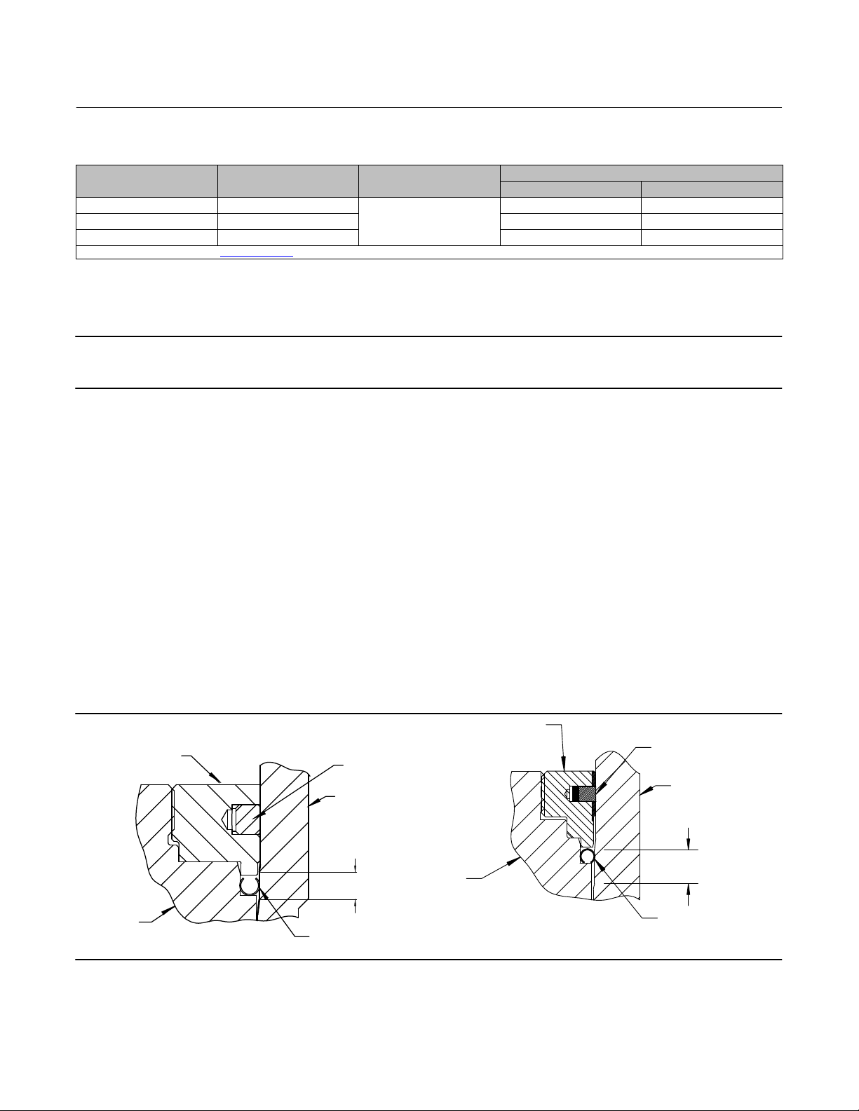
The Bore Seal ring has a C-shaped cross section. The open portion of the C-shape faces the stem side of the plug on
flow up valves. The open portion of the C-shape faces the seating surface of the plug for flow down valves. See
figure 3 for proper orientation. Any uneven marks around the circumference of the ring or any flattening of the ring
shape at its outside diameter are indications of wear and require replacement. Contact your Emerson sales office
Bore Seal ring replacement.
for
ANSI/FCI 70-2 Class IV constructions only: Clean and inspect the guiding and sealing surfaces of the plug assembly.
Inspect the two piston rings (key 45) for signs of wear or damage and replace if necessary. The piston ring is a two
piece design with an outer seal ring and an inner expander ring. The outer ring diameter should be expanded
beyond the diameter of the plug in its free state. It can be shifted within its groove to inspect for uneven wear
around its circumference. The piston ring should require some compression when installing the plug into the cage.
Lack of required compression indicates that the piston ring has worn or relaxed and should be replaced. Vertical
marks in the axial orientation also indicate wear that requires replacement of the ring.
10. Clean and inspect the cage bore for excessive wear. The entire length of the cage bore is either a sealing and/or
guiding surface and any measurable wear requires that the cage be replaced.
11. Welded seat rings remain retained inside the valve body. Clean and inspect the seating surface. Any detectable
damage around the circumference of the seating surface is an indication of wear and requires reconditioning to
ensure seating performance. Contact your Emerson sales office for specific instructions on reconditioning the
seating surface. If the TBX-P has a bolted seat ring, remove the cap screws (key 76) and discard the gasket(s) (key
75) that sit between the valve body and seat ring. Inspect cap screws for damage and excessive wear; replace as
necessary.
9
Page 10

TBX-P Valve
August 2020
Instruction Manual
D104555X012
12. Flow down construction only. Remove the lower cage (key 78); reference figure 9 for guidance in performing this
disassembly. The cage contains sensitive guiding surfaces on its inside and outside diameter and care must be taken
during handling. Protect the cage by placing it on clean cloth or wood while the valve is disassembled.
13. Remove all used gaskets and foreign material from the interior of the valve and from the inlet and outlet openings.
Remove any foreign material that may be in the valve body or trim. Inspect all valve body guiding and sealing
surfaces for any signs of wear.
14. If the valve has been in service, visually inspect the interior of the valve for abnormal wear, erosion, or thermal
fatigue. The gasket surfaces of the valve body and bonnet should be inspected to verify that they are not damaged
and are free of imbedded gasket material. All scratches should be removed by grinding or filing to remove any
interference of the clearance zones between the internal bores and the mating parts. All signs of thermal fatigue
should be carefully evaluated to determine if repair or replacement is necessary. Your local Emerson Service Center
can help determine the severity of damage, if present, and recommend a course of action.
Valve Assembly
1. Cleaning‐‐Make certain that all interior surfaces of the valve body and bonnet (including the packing box) are clean
and free of dirt, including the inlet and outlet openings. All surfaces of the valve interior that receive mating parts
should be given special attention when cleaning. All sliding fit surfaces should be coated with a copper‐based high
temperature anti‐seize lubricant prior to reassembly. Refer to figures 9, 10, and 11 for reference.
If the TBX-P has a bolted seat ring or is flow down orientation, proceed with steps 2 through 4; otherwise, proceed
directly to step 5.
2. Place one gasket (key 75) into the valve body. If the TBX-P is a flow up construction: Install the seat ring (key 24)
onto this gasket surface. If the TBX-P is a flow down construction: Install the lower cage (key 78) onto the gasket
surface ensuring the bolt holes in the cage flange are positioned with the bolt holes in the valve body. Then place
another gasket (key 75) onto the diameter of the lower cage, and install the seat ring (key 24) onto this second
gasket surface.
Note
Horizontal actuator only: TBX-P valves positioned in the process pipeline with a horizontal actuator/trim may require special
attention to ensure that the spiral wound gaskets are maintained in the proper location during the valve assembly procedures
without falling out of the gasket groove. A gasket manufacturer recommends spray adhesive 3M #77 Super Spray Adhesive to
temporarily hold gaskets in place until they are fully contained by the TBX-P valve body and trim components. Please note special
spiral wound gasket-positioning techniques may be recommended. To use the adhesive, lightly spray the gasket groove that the
gasket will be installed in. Also lightly spray one side of the spiral wound gasket that will be contacting the previously coated
gasket groove. Let the spray adhesive set for one minute and then lightly press the spiral wound gasket into the gasket groove.
Other Considerations: Ensure the spiral wound gasket is located in the correct location when contact is made. Trying to remove
the gasket after contact will damage the gasket by pulling out or removing the soft filler/facing material. If the gasket is incorrectly
positioned after applying the spray adhesive it must be removed and discarded. The gasket groove will then need to be cleaned
and a new gasket will need to be installed.
3. Lubricate the seat ring cap screws (key 76) and all surfaces that contact the screws, including the valve body and
seat ring.
4. Torque the cap screws in a crisscross pattern, using no more than 1/4 of the specified torque as indicated in table 3.
Repeat the crisscross pattern, working up to the specified torque in 1/4 increments until the final torque is
achieved. Wait a minimum of 1 minute to allow for gasket/screw relaxation and recheck the torque, adjusting as
necessary.
10
Page 11
Instruction Manual
(1)
D104555X012
TBX-P Valve
August 2020
Table 3. TBX-P (Flow Up and Flow Down) Bolted Seat Ring Torque with Nickel Anti-Seize Lubricant
CAP SCREW SIZE, Inch THREADS PER INCH LUBRICATION
3/8 16
1/2 13 91 67
5/8 11 163 120
1. For other lubricants, contact your Emerson sales office for recommended bolt torque.
Nickel Anti-Seize
RECOMMENDED BOLT TORQUE
N•m lbf•ft
41 30
5. Install one cage gasket (key 43) into the groove in the valve body. If the valve has a horizontal stem orientation,
ensure that the gasket remains in the groove and does not get pinched during cage installation.
Note
Horizontal actuator only: Follow the note in step 2 above to ensure the gaskets are in the proper location during valve assembly.
6. Lubricate the inside of the cage as completely as possible. Insert the lubricated cage (key 21) into the valve body.
Ensure the lower cage diameter slides over the outside diameter of the seat ring. If there is any question regarding
the proper seating of the cage inside the valve body, the following measurements can be taken for confirmation.
Measure the thickness of the cage flange at its largest diameter. Measure the depth of the mating counterbore
where the cage flange engages into the valve body. When assembled with a new cage gasket, the resulting depth
from the top of the valve body to the top of the cage flange should be the difference in these two measured valves,
minus an additional 0.045 inches to allow for the uncompressed gasket.
7. Flow Up Construction only: If applicable, install the magnetite catcher (key 79) by threading into the bore of the
plug (key 22). Apply four tackwelds equally spaced along the circumference of the plug to prevent rotation during
service.
If the TBX-P is an ANSI/FCI 702 Class V construction, proceed with steps 8 through15; otherwise proceed directly to
step 16 for Class IV constructions.
8. The plug assembly includes a plug (key 22), stem (key 23), stem pin (key 53), retainer (key 25), piston ring (key 45)
and Bore Seal ring (key 46). Lubricate the plug assembly at all raised outside diameter surfaces and lubricate the
piston ring(s) and Bore Seal ring.
9. Orient the Bore Seal for correct sealing action based on the process fluid flow direction through the valve, refer to
figure 3 to complete this step.
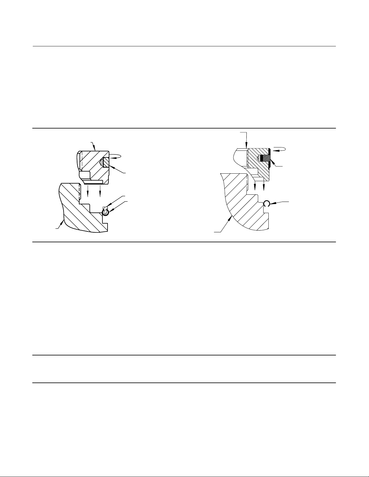
Figure 3. Fisher Bore Seal Construction
RETAINER
PLUG
FLOW-UP
PISTON RING
CAGE
SEATING AREA
BORE SEAL
PLUG
RETAINER
PISTON RING
CAGE
SEATING AREA
BORE SEAL
FLOW-DOWN
10. Place the Bore Seal plug seal over the top of the valve plug. The retainer will help guide the Bore Seal down onto the
plug. Do not force the Bore Seal over the plug (figure 4).
11
Page 12
TBX-P Valve
August 2020
Instruction Manual
D104555X012
11. For the Flowup design, the Bore Seal installation tool (figure 8) must be inserted into the Bore Seal prior to using
the retainer to guide it down the plug.
12. Apply a suitable high‐temperature lubricant to the threads on the plug. Then, place the Bore Seal retainer onto the
plug and tighten the retainer using an appropriate tool such as a strap wrench.
13. If applicable, remove the retainer and then the installation tool. Place the Bore Seal retainer back onto the plug and
tighten the retainer using an appropriate tool such as a strap wrench.
14. Using an appropriate tool such as a center punch, stake the threads on top of the plug in one place to secure the
Bore Seal retainer.
PLUG
RETAINER
PISTON RING
BORE SEAL
FLOW-DOWN
Figure 4. Retainer Guiding Fisher Bore Seal Onto the Plug
RETAINER
PISTON RING
BORE SEAL
INSTALLATION TOOL
BORE SEAL
PLUG
FLOW-UP
15. Install the lubricated plug assembly into the cage. The piston ring(s) should require some radial compression to
collapse into the cage diameter. Do not use a metallic tool to create this piston ring compression as this could
damage the outer sealing diameter of the ring. The plug(s) should slide into the cage(s) smoothly with little effort
until the Bore Seal ring reaches its mating cage diameter. The extra load required to seat the Bore Seal trim seal will
be applied during actuator set up.
16. ANSI/FCI 702 Class IV constructions only: The plug assembly includes a plug (key 22), stem (key 23), stem pin (key
53), and two piston rings (key 45). Lubricate the plug assembly at all raised outside diameter surfaces and lubricate
the piston rings. Install the lubricated plug assembly into the cage. The piston rings should require some radial
compression to collapse into the cage diameter(s). Do not use a metallic tool to create this piston ring
compression, as this could damage the outer sealing diameter of the ring. The plug(s) should slide into the cage(s)
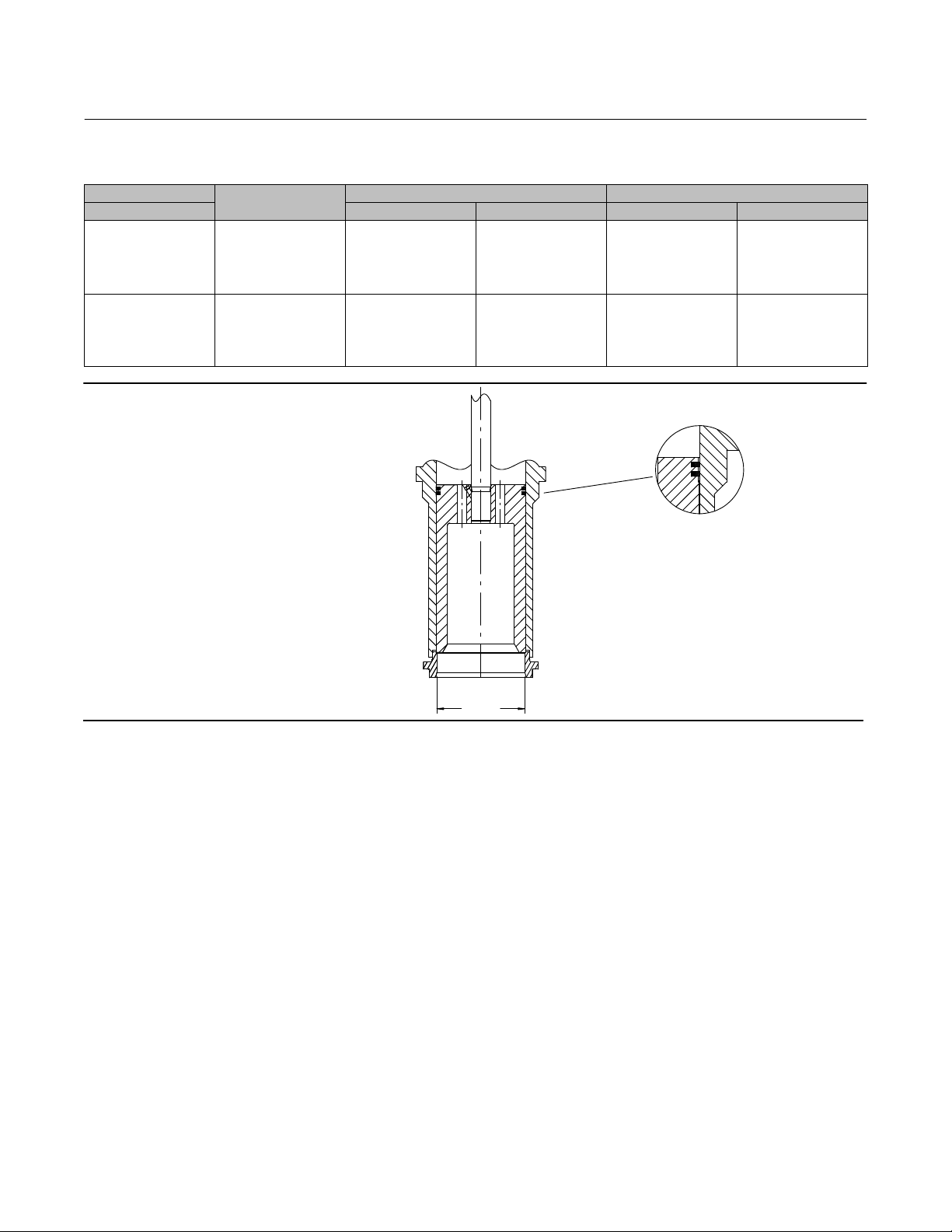
smoothly with little effort. Refer to figures 5 and 7.
17. Install the second cage gasket (key 43) over the cage boss where it will be self‐centering for the mating bonnet
groove.
Note
Stud(s) and nut(s) should be installed such that the manufacturer's trademark and material grade marking is visible, allowing easy
comparison to the materials selected and documented in the Emerson/Fisher serial card provided with this product.
12
Page 13
Instruction Manual
(1)
(2)
D104555X012
TBX-P Valve
August 2020
WARNING
Personal injury or damage to equipment could occur if improper stud and nut materials or parts are used. Do not operate or
assemble this product with stud(s) and nut(s) that are not approved by Emerson/Fisher engineering and/or listed on the
serial card provided with this product. Use of unapproved materials and parts could lead to stresses exceeding the design
or code limits intended for this particular service. Install studs with the material grade and manufacturer's identification
mark visible. Contact your Emerson representative immediately if a discrepancy between actual parts and approved parts
is suspected.
18. Apply appropriate high‐temperature anti‐seize lubricant to the bonnet studs (key 54) and screw them into the valve
body. Back the studs out 1/2 to 1 turns after bottoming the stud in the valve body.
19. Lubricate the bonnet locating surfaces and carefully install the bonnet (key 6). Use care to avoid bending the stem.
20. Install bonnet stud washers (key 52) and nuts (key 55) and hand tighten.
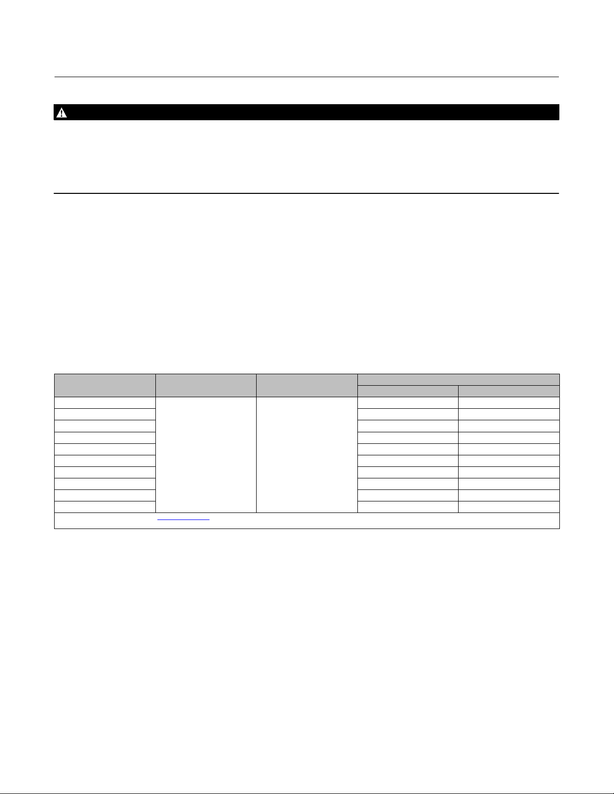
21. Tighten the bonnet nuts (key 55) in a uniform, multistage cross pattern. Monitor the distance between the bonnet
and body and keep it even to ensure that the bonnet is being torqued evenly. It is recommended that torquing be
performed in a minimum of four torque levels until the final torque level is achieved. You may need to torque
multiple times at each torque level to ensure that the bonnet is torqued evenly. Required torque can be found in
table 4. After final torquing, ensure there is an even gap and that the metal-to-metal contact between the valve
body and bonnet is achieved around the entire circumference of the bodybonnet joint.
Table 4. Recommended Body/Bonnet Bolting Torque with Nickel Anti-Seize Lubricant
BOLT SIZE. Inch THREADS PER INCH LUBRICATION
1
1‐1/8 712 525
1‐1/4 942 695
1‐3/8 1268 935
1‐1/2 1654 1220
1‐5/8 2129 1570
1‐3/4 2671 1970
1‐7/8 3308 2440
2 4027 2970
2‐1/4 5776 4260
1. For other lubricants, contact your Emerson sales office for recommended bolt torque.
2. Torques for lubricated studs with heavy hex nuts.
8 Nickel Anti-Seize
RECOMMENDED BOLT TORQUE
NSm LbfSft
522 385
22. After the body/bonnet studs have been torqued to the required level, check the plug movement to ensure that the
plug still moves freely.
23. Recheck cleanliness of the packing box. Insert the packing box ring (key 63) over the stem and into the packing box.
Measure the depth of the packing box before and after ring insertion to be certain that it has traveled to the bottom
of the packing box. Insert packing rings (key 64), after lubricating with high temperature grease, into the packing
box and staggering the gaps on adjacent rings. The packing follower (key 65) can be used to ensure that each
packing ring is pushed down before installing the next packing ring.
24. After all packing rings are installed, thoroughly lubricate the studs (key 69) and insert the packing follower (key 65)
and the packing flange (key 66). Tighten the hex nuts (key 68) tight enough to block leakage but not so tight that
stem travel is hindered. Consult table 5, Recommended Packing Nut Torque for recommended torque levels. Evenly
tighten the nuts to the maximum level, then loosen and retighten to the minimum torque level. After operating,
further tightening may be required to prevent leakage.
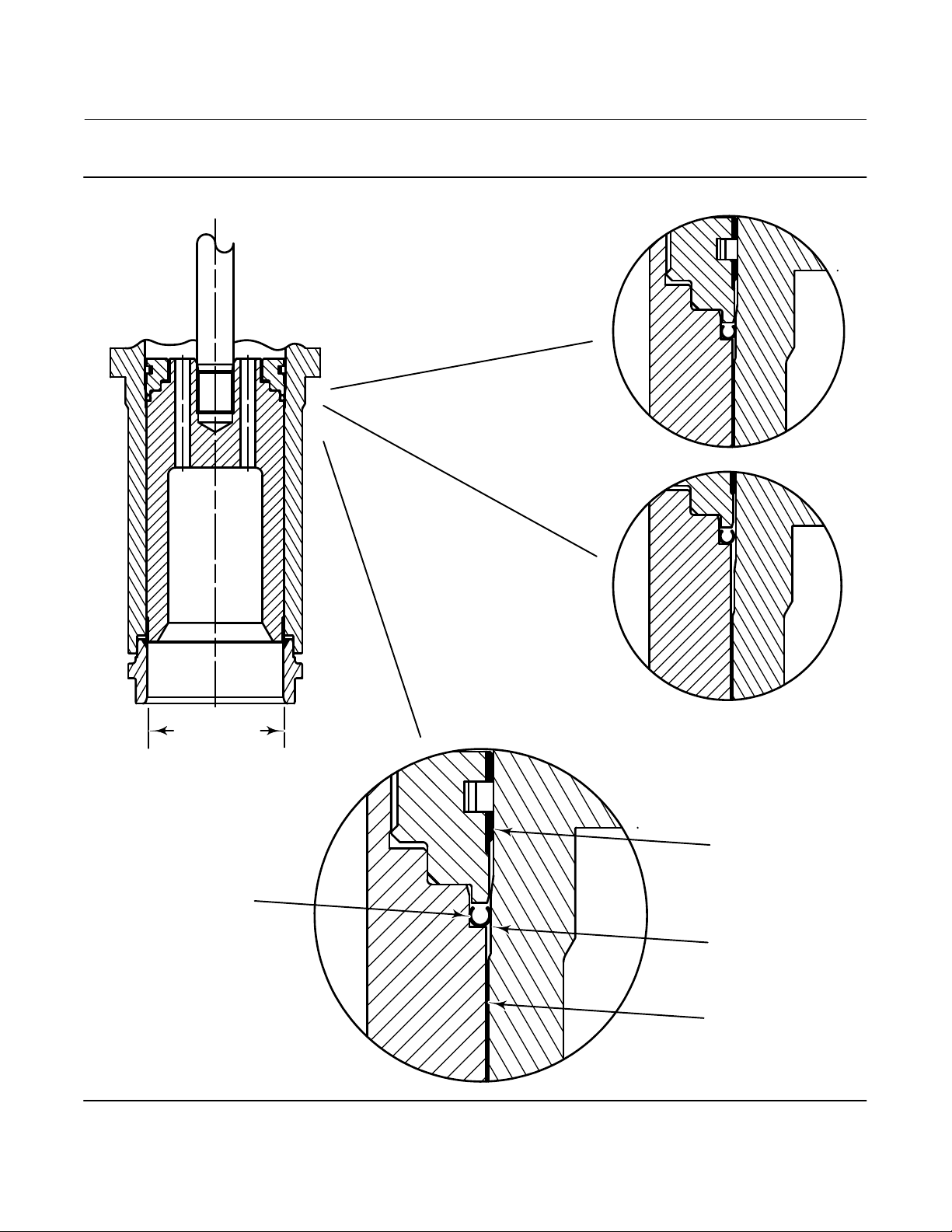
25. Install the actuator on the valve in accordance with manufacturer's standard procedure. If this is an ANSI/FCI 702
Class V construction, the plug assembly will require an additional load and travel to seat the Bore Seal ring (refer to
figures 6 and 7 for details). After calibration of the actuator, the valve should be ready to return to service.
13
Page 14
TBX-P Valve
August 2020
Table 5. Recommended Packing Nut Torque with Anti-Seize Lubricant
STEM DIAMETER
Inch NSm LbfSft NSm LbfSft
1‐1/4
2
ASME PRESSURE
RATING
CL300
CL600
CL900
CL1500
CL2500
CL300
CL600
CL900
CL1500
CL2500
MAXIMUM TORQUE MINIMUM TORQUE
49
67
83
102
122
65
91
120
147
170
108
125
Figure 5. Fisher TBX-P Flow Up Class IV Construction
36
49
61
75
90
48
67
88
Instruction Manual
33
45
56
68
82
59
83
109
133
156
CLASS IV SHUTOFF
DOUBLE PISTON RING
CONFIGURATION
D104555X012
24
33
41
50
60
43
61
80
98
115
PORT SIZE
14
Page 15
Instruction Manual
D104555X012
Figure 6. Fisher TBX-P Flow Up Class V Construction
TBX-P Valve
August 2020
TBX
PORT SIZE
PLUG DIAMETER AT
BORE SEAL TRIM INSTALLATION
BORE SEAL TRIM CONFIGURATION
CLOSED POSITION
OPEN POSITION
CAGE BORE
AT PISTON RING
CAGE BORE AT
BORE SEAL RING SEAT
E0921
CAGE BORE
AT PLUG GUIDE
15
Page 16
TBX-P Valve
August 2020
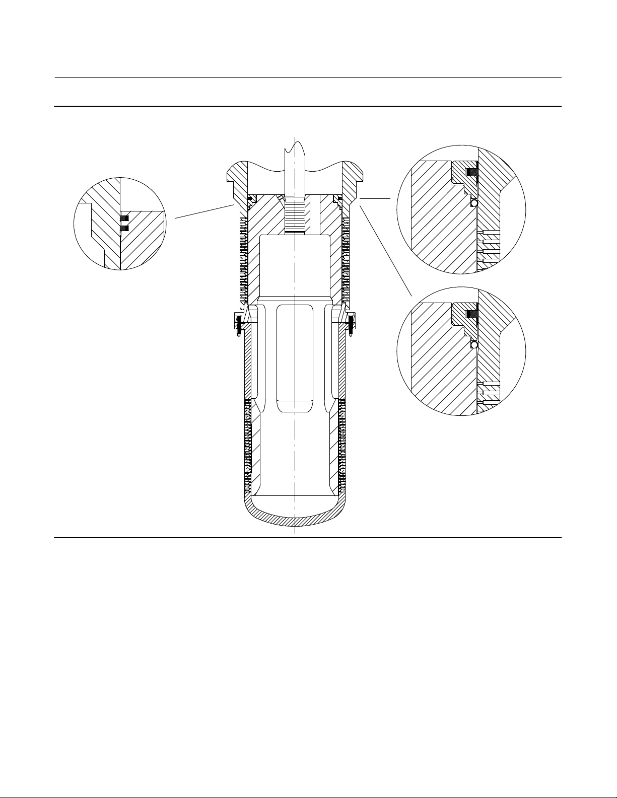
Figure 7. Fisher TBX-P Flow Down Construction
CLASS IV DOUBLE
PISTON RING CONFIGURATION
Instruction Manual
D104555X012
CLASS V BORE SEAL
TRIM CONFIGURATION
CLOSED POSITION
OPEN POSITION
16
Page 17
Instruction Manual
(1)
(1)
(1)
(1)
(1)
(1)
(1)
(1)
D104555X012
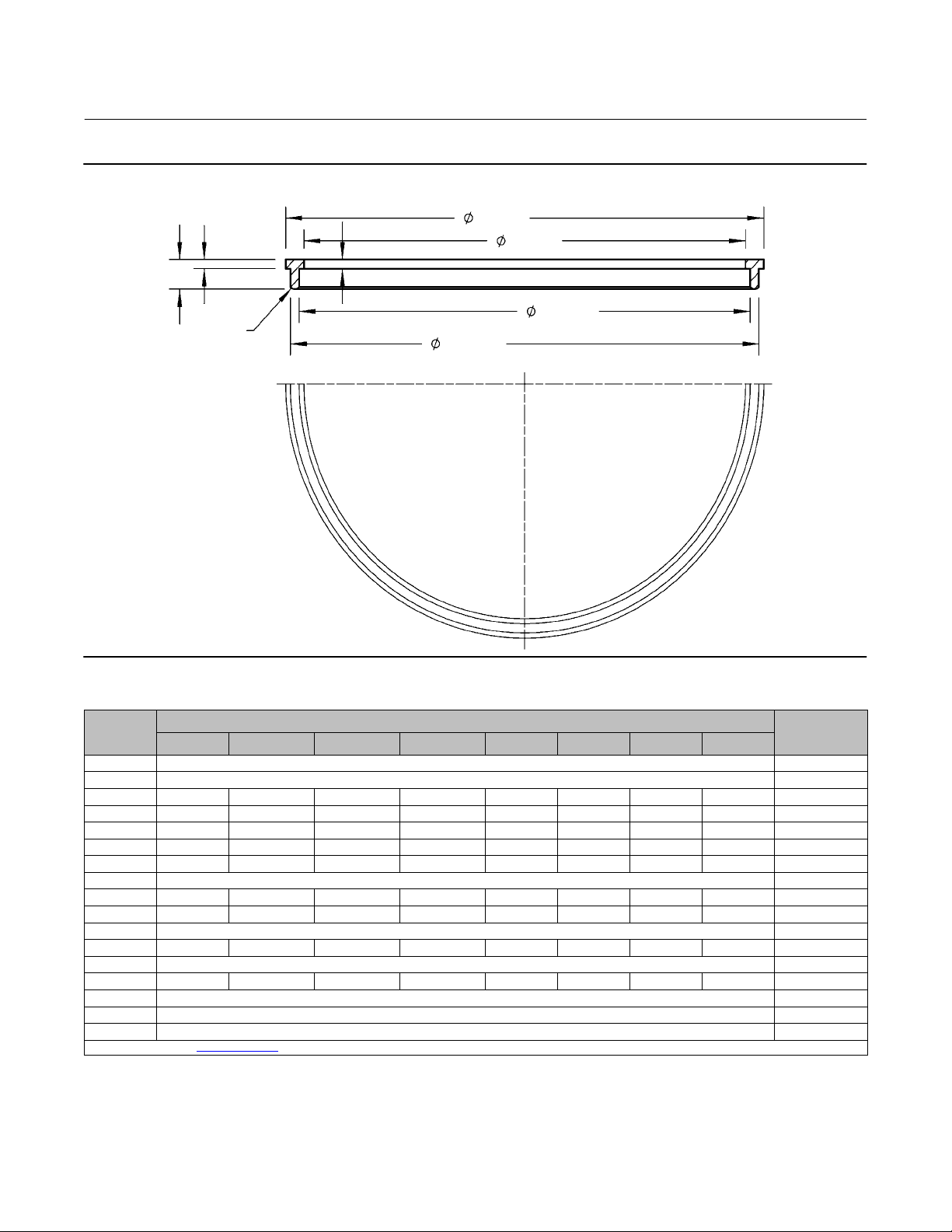
Figure 8. Bore Seal Installation Tool (Flow Up Only)
TBX-P Valve
August 2020
GE22109-A
F
E
A
B
G
C
H
D
Table 6. Bore Seal Installation Tool Dimensions (Flow Up Only)
VALVE
PORT SIZE,
INCH
3.4375
4.28
4.70 4.77 4.35 4.45-4.47 4.67-4.65 0.10 1.10 0.32 R.06 GE18267X012
5.375 5.49 5.07 5.17-5.19 5.39-5.37 0.10 0.10 0.32 R.06 GE22109X012
6.25 6.34 5.92 6.02-6.04 6.24-6.22 0.10 0.10 0.32 R.06 GE18266X012
7.00 7.11 6.69 6.79-6.81 7.01-6.99 0.09 0.10 0.32 R.06 GE18264X012
7.62 7.76 7.34 7.44-7.46 7.66-7.64 0.10 0.10 0.32 R.06 GE18263X012
8.00
9.20 9.39 8.97 9.07-9.09 9.29-9.27 0.10 0.10 0.32 R.06 GE17916X012
10.00 10.12 9.7 9.80-9.82 10.02-10.00 0.10 0.10 0.32 R.06 GE17914X012
11.00
11.20 11.35 10.93 11.015-11.025 11.265-11.255 0.10 0.10 0.32 R.07 GE17905X012
13.75
14.75 14.84 14.424-14.416 14.516-14.536 14.736-14.716 0.1 0.1 0.32 R.05 GE34073X012
16.70
18.25
19.9375
1. For sizes contact your Emerson sales office.
A B C D E F G H
Dimensions, Inches (See Figure 8)
Tool Part
Number
n/a
n/a
n/a
n/a
n/a
n/a
n/a
n/a
17
Page 18
TBX-P Valve
August 2020
Instruction Manual
D104555X012
Parts Ordering
Each TBX-P valve is assigned a serial number that can be found on the bonnet flange. Refer to the serial number when
contacting your Emerson sales office
number and key numbers for each part required. The key numbers in the Parts List and the assembly drawing in figures
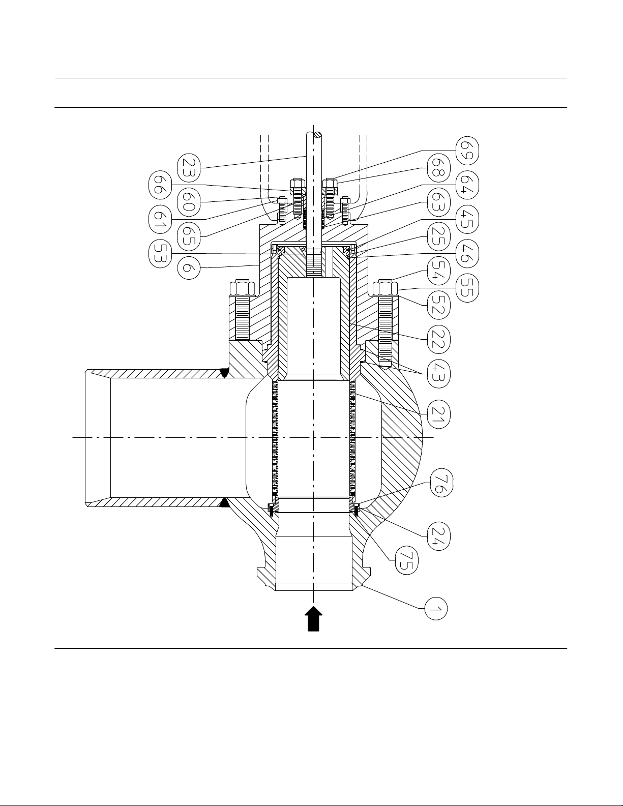
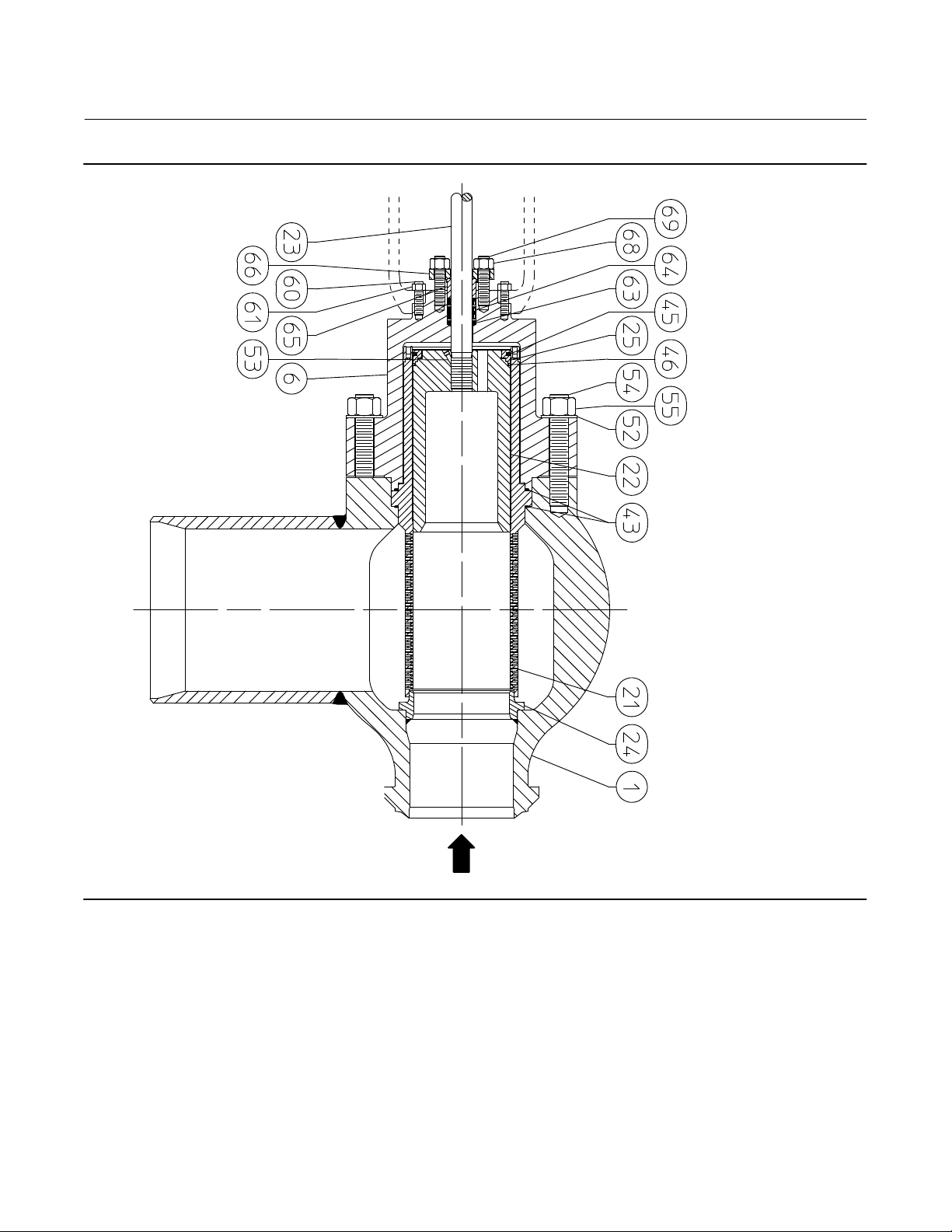
9, 10, and 11 can be used to help in part identification.
WARNING
Use only genuine Fisher replacement parts. Components that are not supplied by Emerson Automation Solutions should
not, under any circumstances, be used in any Fisher valve, because they may void your warranty, might adversely affect the
performance of the valve, and could cause personal injury and property damage.
for technical assistance. When ordering replacement parts, refer to the serial
Parts List
Note
Contact your Emerson sales office
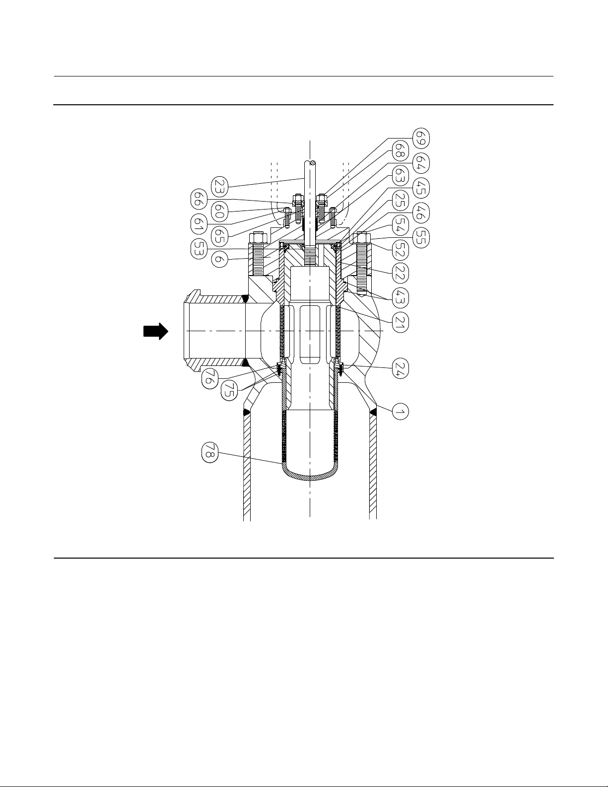
Key Description
1 Body
6 Bonnet
21* Control Cage
22* Control Plug
23* Stem
24 Seat
25 Plug Retainer
for part numbers.
Key Description
43* Cage Gasket, 2 req'd
45* Piston Ring
46* Bore Seal ring
52 Bonnet Stud Washer
53* Stem Pin
54 Bonnet Stud
55 Bonnet Stud Nut
60 Actuator Stud
61 Actuator Stud Nut
63* Packing Box Ring
64* Packing Set
65* Packing Follower
66* Packing Flange
68* Hex Nut
69* Stud
75* Gasket
76* Seat Ring Cap Screws
78* Lower Cage
79 Magnetite Catcher (not shown)
18
*Recommended spare parts
Page 19
Instruction Manual
D104555X012
Figure 9. Fisher Flow Down TBX-P Assembly with Bolted Seat Ring
FLOW
TBX-P Valve
August 2020
19
Page 20
TBX-P Valve
August 2020
Figure 10. Fisher Flow Up TBX-P Assembly with Bolted Seat Ring
Instruction Manual
D104555X012
20
FLOW
Page 21
Instruction Manual
D104555X012
Figure 11. Fisher Flow Up TBX-P Assembly with Welded Seat Ring
TBX-P Valve
August 2020
FLOW
21
Page 22

TBX-P Valve
August 2020
Instruction Manual
D104555X012
22
Page 23

Instruction Manual
D104555X012
TBX-P Valve
August 2020
23
Page 24

TBX-P Valve
August 2020
Instruction Manual
D104555X012
Neither Emerson, Emerson Automation Solutions, nor any of their affiliated entities assumes responsibility for the selection, use or maintenance
of any product. Responsibility for proper selection, use, and maintenance of any product remains solely with the purchaser and end user.
Fisher, Whisper Trim, and WhisperFlo are marks owned by one of the companies in the Emerson Automation Solutions business unit of Emerson Electric Co.
Emerson Automation Solutions, Emerson, and the Emerson logo are trademarks and service marks of Emerson Electric Co. All other marks are the property
of their respective owners.
The contents of this publication are presented for informational purposes only, and while every effort has been made to ensure their accuracy, they are not
to be construed as warranties or guarantees, express or implied, regarding the products or services described herein or their use or applicability. All sales are
governed by our terms and conditions, which are available upon request. We reserve the right to modify or improve the designs or specifications of such
products at any time without notice.
Emerson Automation Solutions
Marshalltown, Iowa 50158 USA
Sorocaba, 18087 Brazil
Cernay 68700 France
Dubai, United Arab Emirates
Singapore 128461 Singapore
www.Fisher.com
24
E 2020 Fisher Controls International LLC. All rights reserved.
 Loading...