

Page 1

SERVICE MANUAL FOR IW900 SERIES INFANT
WARMER & ACCESSORIES
MANUFACTURED BEFORE JUNE 2008
IW910 Baby Control Mobile Infant Warmer
IW920 Manual Control Mobile Infant Warmer
IW930 Series Baby Control CosyCot™ Infant Warmer
IW950 Series Manual Control CosyCot™ Infant Warmer
IW980 Baby Control Wall Mount Infant Warmer
IW990 Manual Control Wall Mount Infant Warmer
IW900 Series Infant Warmer Accessories
Page 2
International Fisher & Paykel Healthcare Ltd
15 Maurice Paykel Place, East Tamaki,
Auckland 2013
P O Box 14 348, Panmure, Auckland 1741
New Zealand
United States Fisher & Paykel Healthcare Inc
15365 Barranca Parkway Irvine
CA 92618
USA
Australia Fisher & Paykel Healthcare Pty Ltd
36-40 New Street
P O Box 167, Ringwood
Tel: +64 9 574 0100
Fax: +64 9 574 0158
Sales info: [email protected]
Investor info: [email protected]
Site Feedback: [email protected]
Tel: +1 800 446 3908 or
+1 949 453 4000
Fax: +1 949 453 4001
Email: [email protected]
Tel: +61 3 9879 5022
Fax: +61 3 9879 5232
Email: [email protected]
Melbourne, Victoria 3134
Australia
China Fisher & Paykel Healthcare Guangzhou Ltd
B910, 11 Caipin Lu,
Guangzhou Science City,
Guangzhou Economic & Technological Development
Tel: +86 20 3205 3486
Fax: +86 20 3205 2132
Email: [email protected]
District,
Guangzhou, China 510663
France/Benelux Fisher & Paykel Healthcare SAS
10, avenue du Québec – Bâtiment F5
Silic 512 – Villebon-s/Yvette
Tel: +33 1 64 46 52 01
Fax: +33 1 64 46 52 21
Email: [email protected]
91946 Courtaboeuf Cedex
France
Netherlands Fisher & Paykel Healthcare SAS
Weegschaalstraat 3
5632 CW Eindhoven
Tel: +31 4021 63555
Fax: +31 4021 63354
Email [email protected]
Postbus 4122
5604 EC Eindhoven
Italy (Luciano's home address)
Via Alfredo Baccarini, 46
00179
Tel +39 06 7839 2939
Fax +39 06 7814 7709
Email: [email protected]
Rome, Italy
Spain Postal only:
Velázquez, 86-B Bajo centro
28006 Madrid, Spain
Germany/Austria Fisher & Paykel Healthcare GmbH & Co KG
Hundsberger Straβe 45, 73642 Welzheim
Postfach 1103, 73636 Welzheim
Tel: +34 902 013 346
Fax +34 902 013 379
Email: [email protected]
Tel: +49 7182 93777 0
Fax: +49 7182 93777 99
Email: [email protected]
Germany
Austria Freephone (from within Austria only)
Tel: 0800 29 31 23
Fax: 0800 29 31 22
Switzerland Fisher & Paykel Healthcare
GmbH & Co. KG Welzheim
Zweigniederlassung Egg/Zurich
Freephone (from within Switzerland only)
Tel: 0800 83 47 63
Fax: 0800 83 47 54
Brunnwiese 76
CH – 8132 Egg
Switzerland
India Fisher & Paykel Healthcare Ltd India Branch
# 30, CQAL Layout,
Sahakar Nagar, Bangalore-560 092
Tel: +91 80 4123 6041/42/43
Fax: +91 80 4123 6044
Email: [email protected]
Karnataka, India
Japan Fisher & Paykel Healthcare KK
Libera Kayaba-cho Bldg. 5th Floor
Tel: +81 3 3661 7205
Fax: +81 3 3661 7206
3-8-10 Nihonbashi Kayaba-cho
Chuo-ku, Tokyo 103-0025
Japan
Middle East New Zealand Technology Oasis
Al Thuraya Tower 1 - Office 704 / 7th Floor
Dubai Internet City
Tel: +9 71 4 360 0849
Fax: +9 71 4 368 8110
E-mail: [email protected]
Dubai - P.O.Box 64096
UAE
Sweden Fisher & Paykel Healthcare AB
Spjutvägen 6
175 61 Järfälla
Tel: +46 8 564 76 680
Fax: +46 8 36 63 10
Email: [email protected]
Sweden
United Kingdom /
Ireland
EU Authorised Representative
Fisher & Paykel Healthcare Ltd
Unit 16, Cordwallis Park
Clivemont Road
Maidenhead
Berkshire SL6 7BU
United Kingdom
UK:
Tel: +44 1628 626 136
Fax: +44 1628 626 146
Email: [email protected]
Ireland:
Republic of Ireland: 1800 409 011
Northern Ireland: 0800 132 189
IW900 Series Service Manual
Manufactured Before June 2008
PART NUMBER :
ISSUE DATE :
ISSUE NUMBER :
PAGE :
185041130
November 2008
I
2
Page 3

Intended Use (including indications for use)
The IW900 series Infant Warmers are designed to provide warmth to infants in the first few
weeks of life, when an infant's self-thermoregulation capacity may be reduced, or if external
thermal support is required or desirable. This may include neonates (including premature/low
birth-weight neonates) in Labor and Delivery (L&D) Room applications, thermal support of
premature/low birth-weight neonates and critically ill infants in neonatal intensive care units
(NICUs) and thermal support of infants/pediatrics less than 10kg in hospital nurseries. Situations
which necessitate unobstructed access to an infant or neonate, including during resuscitation or
surgical procedures, may indicate the need for a radiant heat source instead of equivalent
support devices such as infant incubators. The IW900 series warmers may therefore also be
used in the Operating Room.
The IW930/IW950 series Infant warmers are additionally intended to be used for intra-hospital
transport between the above stated specialist treatment areas.
The IW900 series infant warmer is not designed or intended to be used outside of the hospital
environment. The IW900 series infant warmer is not designed or intended to be used in
ambulatory vehicles.
CAUTION
Only competent individuals trained in the repair of this equipment should attempt to service it as
detailed in this manual.
Detailed information for more extensive repairs is included in the service manual solely for the
convenience of users having proper knowledge, tools and test equipment, and for service
representatives trained by Fisher & Pakyel Healthcare.
Fisher & Paykel Healthcare has a policy of continued product improvement and reserves the
right to alter specifications without notice.
This Service Manual is valid for warmers manufactured before June 2008. For Infant Warmers &
accessories manufactured after this date refer to 185045312 Rev A.
Warranty
Subject to any agreement to the contrary, the product described in this manual is warranted
against defects in materials and workmanship for one year from the date of shipment. However,
the warranty is void if the product is damaged as a result of mishandling, accident or misuse. In
no event shall the manufacturer be liable for incidental or consequential damages (e.g. loss of
use) resulting from breach of warranty. All other expressed and implied warranties under law
are excluded to the extent that it can be lawfully excluded.
COPYRIGHT © 2008 FISHER & PAYKEL HEALTHCARE LTD.
IW900 Series Service Manual
Manufactured Before June 2008
PART NUMBER :
ISSUE DATE :
ISSUE NUMBER :
PAGE :
185041130
November 2008
I
3
Page 4

CONTENTS
PART 1: SYMBOLS AND DEFINITIONS...............................................................................................................6
PART 2: OPERATION AND GENERAL INFORMATION......................................................................................7
2.1 PRODUCT OVERVIEW..................................................................................................................................7
2.2 HEATER POWER CONTROL..........................................................................................................................8
2.3 CONTROL PANEL ........................................................................................................................................9
2.4 ALARMS ...................................................................................................................................................10
2.5 INFORMATION MODE .................................................................................................................................11
2.6 ERROR CODES .........................................................................................................................................12
2.7 SPECIFICATION FOR IW910 AND IW920 MOBILE INFANT WARMERS ............................................................13
2.8 SPECIFICATION FOR IW93X AND IW95X COSYCOT™ INFANT WARMERS.....................................................15
SPECIFICATION FOR IW960 AND IW970 WALL MOUNT COSYCOT™ INFANT WARMERS ...............................16
2.9 SPECIFICATION FOR IW980 AND IW990 WALL MOUNT INFANT WARMERS ...................................................17
2.10 ENVIRONMENTAL SPECIFICATIONS.............................................................................................................18
2.11 EQUIPMENT CLASSIFICATIONS...................................................................................................................18
2.12 STANDARDS AND APPROVALS ...................................................................................................................18
2.14 EMC .......................................................................................................................................................19
PART 3: MAINTENANCE AND SERVICING.......................................................................................................24
3.1 MAINTENANCE SCHEDULE.........................................................................................................................24
3.2 SAFETY CHECK ........................................................................................................................................24
3.3 SYSTEM CHECK ........................................................................................................................................25
3.4 FUNCTIONAL CHECK .................................................................................................................................26
3.5 SERVICE PROCEDURES- REPLACEMENT ....................................................................................................27
3.6 SERVICE PROCEDURES – ADJUSTMENT .....................................................................................................30
3.7 RECOMMENDED MAINTENANCE CHECKLIST................................................................................................33
PART 4: CLEANING.............................................................................................................................................34
4.1 GENERAL CLEANING .................................................................................................................................34
PART 5: IW900 SERIES ELECTRONICS............................................................................................................36
5.1 TROUBLESHOOTING FLOW CHART .............................................................................................................36
5.2 CIRCUIT OVERVIEW ..................................................................................................................................37
5.3 CIRCUIT DESCRIPTION ..............................................................................................................................38
5.4 PCB COMPONENT LOCATIONS ..................................................................................................................40
5.5 CIRCUIT SCHEMATICS ...............................................................................................................................43
5.5 CIRCUIT SCHEMATICS, CONTINUED. ...........................................................................................................50
PART 6: HEAD AND COLUMN ...........................................................................................................................51
6.1 HEAD ASSEMBLY ......................................................................................................................................51
6.2 IW900 CONTROLLER ASSEMBLY ...............................................................................................................54
6.3 IW910/920 MOBILE COLUMN ASSEMBLY ...................................................................................................56
6.4 IW93X/95X COSYCOT™ COLUMN ASSEMBLY............................................................................................59
6.5 IW960/970 WALLMOUNT COSYCOT™ COLUMN ASSEMBLY........................................................................66
6.6 IW980/990 WALL MOUNT COLUMN ASSEMBLY..........................................................................................68
PART 7: COSYCOT™ BASSINET.......................................................................................................................70
7.1 BASSINET CHANGE HISTORY.....................................................................................................................70
7.2 SIDE PANEL CHANGE HISTORY..................................................................................................................71
7.3 BASSINET (3.1) ASSEMBLY (IW93X, IW95X, IW960 & IW970)...................................................................72
7.4 BASSINET (3) ASSEMBLY (IW93X, IW95X, IW960 & IW970)......................................................................74
7.5 BASSINET (2.5) ASSEMBLY (IW93X, IW95X, IW960 & IW970)...................................................................76
7.6 BASSINET (2.1) ASSEMBLY (IW93X, IW95X)..............................................................................................78
7.7 BASSINET (2.0) ASSEMBLY (IW93X, IW95X, IW960 & IW970)...................................................................80
7.8 BASSINET (1.0) ASSEMBLY (IW93X, IW95X, IW960 & IW970)...................................................................82
7.9 BASSINET SIDE PANEL ASSEMBLY (IW93X, IW95X, IW960 & IW970) ........................................................84
7.10 043042190 BASSINET TRANSPORT HANDLE ASSEMBLY.............................................................................97
7.11 BASSINET ARMS AND BRAKE ASSEMBLY ....................................................................................................98
7.12 BASSINET TILT LINK ASSEMBLY ...............................................................................................................100
IW900 Series Service Manual
Manufactured Before June 2008
PART NUMBER :
ISSUE DATE :
ISSUE NUMBER :
PAGE :
185041130
November 2008
I
4
Page 5

PART 8: IW93X/95X COSYCOT™ BASE ASSEMBLY...................................................................................101
PART 9: GAS ACCESSORIES.........................................................................................................................104
9.2 GAS ACCESSORY SERVICE INFORMATION..............................................................................................106
9.3 498040139 OXYGEN PRESET REGULATOR PARTS LIST.........................................................................108
9.4 900IW101/103/105 OXYGEN GAS SUPPLY MODULES...........................................................................109
9.5 900IW102/104/106 OXYGEN/AIR GAS SUPPLY MODULES ....................................................................113
9.6 900IW110/111/112/113 FLOWMETER MODULES..................................................................................118
9.7 900IW115/116/117/117G/118/118Y SINGLE FLOWMETERS ................................................................120
9.8 900IW14X GAS CYLINDER BLOCKS (DISCONTINUED FROM 1
ST
MARCH 1999)........................................123
9.9 900IW15X GAS ACCESSORY BLOCKS ..................................................................................................124
9.10 900IW16X LOW PRESSURE GAS MODULES..........................................................................................127
9.11 900IW171 OXYGEN REGULATOR .........................................................................................................131
9.12 900IW181 SUCTION BLOCK DISS........................................................................................................132
9.13 ASSOCIATED GAS ACCESSORIES ..........................................................................................................133
PART 10: GENERAL ACCESSORIES...............................................................................................................137
10.1 900IW001 DUOSENSE™ SKIN SENSOR ...............................................................................................137
10.2 900IW204/205 X-RAY TRAY ASSEMBLY (IW93X, IW95X, IW960 & IW970)..........................................139
10.3 900IW215 SCALES MOUNTING KIT.......................................................................................................143
10.4 900IW301 SHORT MOUNTING POLE .....................................................................................................144
10.5 900IW302 LONG MOUNTING POLE .......................................................................................................145
10.6 900IW303 SHELF / MEDELA PHOTOTHERAPY MOUNTING BLOCK ...........................................................146
10.7 900IW305 HOOK CABLE / HOSE IW2G ................................................................................................147
10.8 900IW306 ACCESSORY HOOK IW2G ...................................................................................................148
10.9 900IW313 IV QUAD HOOK POLE –BENT.................................................................................................149
10.10 900IW314 NATUS PHOTOTHERAPY MOUNTING BRACKET........................................................................150
10.11 900IW312A/J UPS MOUNTING KIT FOR COSYCOT™ INFANT WARMERS ...............................................151
10.12 900IW401 SIDE SHELF AND SUPPORT BLOCK.......................................................................................156
10.13 900IW408 STORAGE DRAWER SYSTEM................................................................................................157
10.14 900IW403/5 STORAGE BINS WITH 900IW308 BIN MOUNTING POLE ......................................................158
PART 11: MEDELA PHOTOTHERAPY–900IW501XX/900IW502XX................................................................159
11.1 PHOTOTHERAPY PERFORMANCE CHARACTERISTICS AND SPECIFICATIONS..............................................159
PHOTOTHERAPY SERVICE INFORMATION ...............................................................................................161
11.2 900IW501XX PHOTOTHERAPY LAMP ....................................................................................................165
11.3 900IW502AX PHOTOTHERAPY POWER MODULE – 230V .......................................................................169
PART 12: WARMER IDENTIFICATION..............................................................................................................173
12.1 INFANT WARMER SERIAL NUMBER EXPLANATION...................................................................................173
IW900 Series Service Manual
Manufactured Before June 2008
PART NUMBER :
ISSUE DATE :
ISSUE NUMBER :
PAGE :
185041130
November 2008
I
5
Page 6
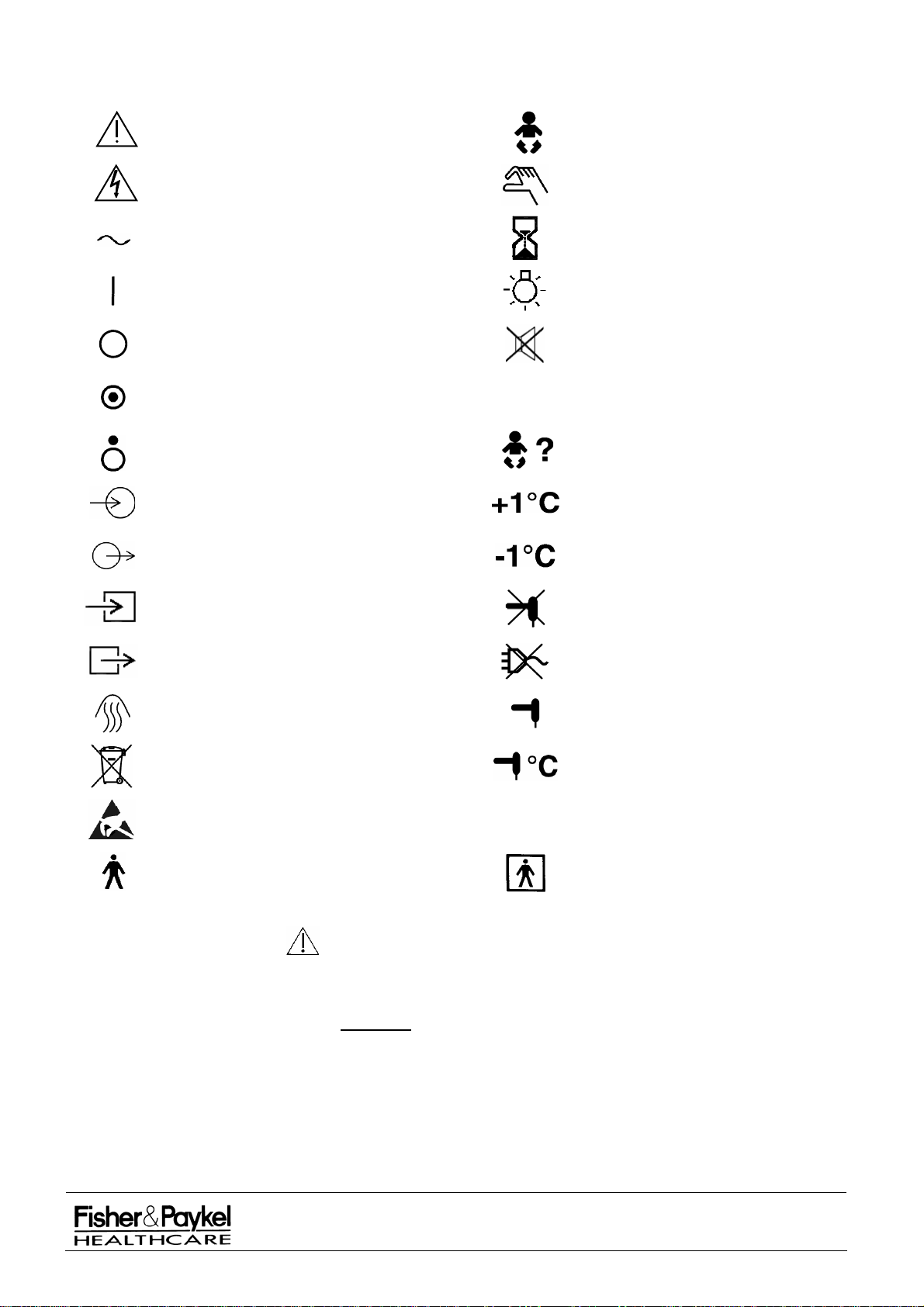
PART 1: Symbols and Definitions
Attention: Consult Accompanying
Documents
Warning: Electric Shock Hazard
Baby Mode (Servo mode)
Manual Model
Alternating Current
Timer
Power On
(connect to the mains power supply)
Power Off
(disconnect from the mains power
supply)
Power On (only for part of equipment)
25%
Light
Mute (alarm silence)
25% power level
(Prewarm or Standby Mode)
Power Off (only for part of equipment)
Check Baby
Electrical Input
High Temperature Alarm
Electrical Output
Low Temperature Alarm
Gas Inlet
Gas Outlet
Heater
Contact your local distributor to recycle
waste electronic goods responsibly
Caution: ESD sensitive
Type B Applied Part
Warning Statement
WARNING
A WARNING statement refers to the conditions when the possibility of
injury to the patient or user exists if a procedure is not followed correctly.
Caution Statement CAUTION
Sensor Disconnect
Power Disconnect
Temperature Sensor
Sensor Temperature ºC
Type BF Applied Part
A Caution statement indicates the possibility of damage to the equipment
exists if a procedure is not followed correctly.
Note Statement NOTE:
A Note statement provides additional information intended to clarify points,
procedures or instructions.
IW900 Series Service Manual
Manufactured Before June 2008
PART NUMBER :
ISSUE DATE :
ISSUE NUMBER :
PAGE :
November 2008
185041130
I
6
Page 7

PART 2: Operation and General Information
2.1 Product Overview
INTRODUCTION The Fisher & Paykel range of radiant warmers are specifically designed
to provide a controlled source of warmth to Neonates.
MODELS The IW910 Baby Control and IW920 Manual Control Mobile Infant
Warmers provide truly mobile and height adjustable warming wherever
needed.
The IW930 Series Baby Control and IW950 Series Manual Control
CosyCot™ Infant Warmers combines an integrated bassinet with four
base accessory options:
IW931 Standard Size Bassinet & Mattress – Preset Base
IW932 Standard Size Bassinet & Mattress – Electric Elevator Base
IW933 Long Bassinet & Mattress – Preset Base
IW934 Long Bassinet & Mattress – Electric Elevator Base
IW951 Standard Size Bassinet & Mattress – Preset Base
IW952 Standard Size Bassinet & Mattress – Electric Elevator Base
IW953 Long Bassinet & Mattress – Preset Base
IW954 Long Bassinet & Mattress – Electric Elevator Base
To these base models optional accessories can be added to suit you
own particular warming needs
The IW960 Baby Control and IW970 Manual Control Wall Mount
CosyCot™ Infant Warmers combine the integrated CosyCot™ bassinet
with the benefits of wall mounting.
The IW980 Baby Control and IW990 Manual Control Wall Mount Infant
Warmers provide discrete and convenient space saving warming.
HEAT CONTROL In Baby Mode (IW910, IW93x, IW960 & IW980 only), the infant warmers
provide stable control of the baby's skin temperature by automatically
adjusting the heater power to compensate for varying physiological and
environmental conditions. This is achieved using a microprocessor which
measures and updates the baby’s temperature ten times every second.
In Manual Mode, all infant warmers provide user-adjustable heater power
and the option to monitor the baby’s skin temperature using the
DuoSense™ skin sensor.
In Prewarm Mode all models provide alarm and trouble-free pre-warming
of the heater.
DUOSENSE™ SKIN SENSOR Safety is further enhanced by DuoSense™ skin sensor. This sensor
measures the desired skin temperature using two independent sensors.
These sensors are continuously compared to ensure accurate and
reliable skin temperature measurements.
OPERATING MANUAL This technical manual is intended to be used in conjunction with the 900
Series Operating Manual (see part numbers below) and Installation and
Assembly Instruction Sheets. The operating manuals must be read
thoroughly and all instructions, warnings, cautions and notes thoroughly
understood by all personnel working with warmers prior to use.
185044990 MANUAL OP IW900 CD MULTI-LANG
IW900 Series Service Manual
Manufactured Before June 2008
PART NUMBER :
ISSUE DATE :
ISSUE NUMBER :
PAGE :
185041130
November 2008
I
7
Page 8

2.2 Heater Power Control
2.2.1 Modes of Power Control
PREWARM MODE Power is fixed at 25% (total irradiance at 68 cm < 10 mW/cm
MANUAL MODE Power is adjustable in the range 0% to 100% in 5% steps.
BABY/SERVO MODE Power is automatically controlled according to the measured skin
2.2.2 Description of Power Control
POWER COMPENSATION The actual mains power delivered to the element is not equal to the
In all power delivery modes the amount of mains power delivered to the
2
). This is
sufficiently low that minimal alarms need to be active but sufficiently
high that the heating element will keep warm and be ready for
immediate use.
temperature to achieve the desired set temperature. The set
temperature is adjustable from 34.5°C to 37.5°C in 0.1°C steps.
power displayed on the front panel of the controller, as the device is
continually monitoring the mains voltage level and compensating for
any slumps and surges that may occur.
element is calculated as shown below.
P
PP
DisplayedDelivered
Ceiling
100
2
V
%5.7
2
V
Where:
Displayed
P
Ceiling
V
75%.
is the displayed power level (Power Display).
is the power ceiling (currently 100% for all models).
is the nominal line voltage less 7.5% (e.g. 213V for 230V
P
device).
V
is the current line voltage.
P
Delivered
is the actual amount of mains power delivered to the
element. Actual power delivered should be constant for constant power
displayed.
RESOLUTION AND DUTY CYCLE Power to the element is controlled with a triac and switched only on
mains zero crossings to maximise electromagnetic compatibility.
When in Baby Mode, the power is controlled to a resolution of 1%.
Power is delivered in an optimally smooth pattern of mains pulses
which repeats every 2 seconds at 50 Hz (1.7 seconds at 60 Hz). This
even power control helps to reduce ripple in the baby or patients skin
temperature. The power level is automatically adjusted ten times every
second.
IW900 Series Service Manual
Manufactured Before June 2008
PART NUMBER :
ISSUE DATE :
ISSUE NUMBER :
PAGE :
185041130
November 2008
I
8
Page 9

2.3 Control Panel
2.3.1 All Infant Warmer Models
LIGHT INDICATOR AND BUTTON The Light Button toggles the examination light off and on. The Light
PREWARM INDICATOR AND BUTTON The Prewarm Button begins Prewarm Mode. The Prewarm Indicator
MANUAL INDICATOR AND BUTTON The Manual Button begins Manual Mode. The Manual Indicator will be
APGAR INDICATOR AND BUTTON The Apgar Button starts an Apgar timer with Apgar tones at 1 min, 3
TIMER DISPLAY Displays the current time of the Apgar timer, timer 1 and timer 2 when
BABY SKIN TEMPERATURE DISPLAY Displays the current baby skin temperature when a skin sensor is
Indicator is lit when the light is on and extinguished when the light is off.
If the light fails during use a short tone will sound and the light indicator
will extinguish. If the light is turned on with a faulty bulb, the indicator
will turn on, there will be a short tone and the indicator will extinguish.
will be lit if the button is pushed.
lit if the button is pushed.
min (optional), 5 min, and 10 min. The indicator lights while the Apgar
timer is active to help distinguish it from a count down timer. The Apgar
timer will blank at 60 minutes. Re-pressing the button will clear the
timer.
they are active. Also used by Information Mode.
inserted in Manual Mode or Baby Mode. Displays 'HI' if the temperature
exceeds 50°C. Displays '---' in the event of a sensor disconnect alarm.
Blanks when in Prewarm Mode or when no skin sensor is inserted in
manual mode.
POWER DISPLAY Displays the current output power level in the range 0% to 100% in 5%
steps.
CONTROL KNOB Adjusts set temperature in Baby Mode and set power level in Manual
Mode. Adjusts preset start times when either the Timer 1 Button or the
Timer 2 Button is held down (IW910, IW93x, IW960 & IW980 only).
Also used in Information Mode (see Section 2.5).
2.3.2 IW910, IW93x, IW960 and IW980 Servo Control Models
BABY INDICATOR AND BUTTON The Baby Button begins Baby Mode. The Baby Indicator will be lit if the
button is pushed.
TIMER1 BUTTON Starts Timer 1 at the preset start time. Holding the button down allows
the Timer 1 preset start time to be adjusted with the control knob. Repressing the button will clear the timer.
TIMER2 BUTTON Starts Timer 2 at the preset start time. Holding the button down allows
the Timer 2 preset start time to be adjusted with the control knob. Repressing the button will clear the timer.
MUTE BUTTON Inactive unless one of the following alarms is active: Sensor Disconnect
alarm, High Temperature alarm, Low Temperature alarm and Check
Baby alarm. In each case pressing the Mute Button silences the
audible alarm (for 10 minutes) and in the case of the Check Baby alarm
it cancels the visual alarm as well (for another 15 minutes).
SET TEMPERATURE DISPLAY Displays the current set temperature when in Baby Mode. Blanks in
Prewarm Mode or Manual Mode. Also used by Information Mode.
IW900 Series Service Manual
Manufactured Before June 2008
PART NUMBER :
ISSUE DATE :
ISSUE NUMBER :
PAGE :
185041130
November 2008
I
9
Page 10

2.4 Alarms
2.4.1 IW910, IW93x, IW960 and IW980 Servo Control Models
CHECK BABY ALARM In Baby Mode this alarm means the output power has been at 100% for
at least 15 minutes indicating that the baby is slow rising to the set
temperature and should be checked. In Manual Mode this alarm
means the output power has been above 25% for at least 15 minutes
indicating that the baby should be checked.
HIGH SKIN TEMP. ALARM In Baby Mode this alarm means the baby skin temperature exceeds the
set temperature by at least 1.0°C. In Prewarm Mode or Manual Mode
this alarm means the baby skin temperature exceeds 39°C.
LOW SKIN TEMP. ALARM In Baby Mode this alarm means the set temperature exceeds the baby
skin temperature by at least 1.0°C. This alarm is not active in Prewarm
Mode and Manual Mode. This alarm is disabled for 15 minutes each
time baby mode is started and re-enabled each time the skin
temperature gets within 0.5°C of set temperature.
SENSOR DISCONNECT ALARM In Baby Mode this alarm means a problem has been detected with the
skin temperature sensor. This may mean: (a) If '---' is flashing on the
Baby Skin Temperature Display the sensor plug is not inserted fully into
the socket, and/or (b) that one of the thermistor beads within the
DuoSense™ skin sensor does not agree with the other so that the
sensor can no longer be considered accurate. A bead mismatch alarm
occurs within 25 seconds of the sensor being plugged in. Both
meanings apply in Baby Mode, meaning (b) only applies in Manual
Mode and neither apply in Prewarm Mode.
2.4.2 IW920, IW95x, IW970 and IW990 Manual Control Models
CHECK BABY ALARM This alarm has three meanings:
(a) Manual Mode 15 Minutes
The infant warmer has been running in Manual Mode at over 25%
power for more than 15 minutes. The baby should be checked.
(b) Skin Temperature > 39°C
This alarm is accompanied by a flashing Baby Skin Temperature
Display (which is > 39°C). The baby should be checked.
(c) Skin Sensor Faulty
The DuoSense™ skin sensor feature of the infant warmer has detected
a fault with the skin sensor. This alarm is accompanied by a flashing
Baby Skin Temperature Display. Ensure that the skin sensor is fully
plugged in. If skin sensor is faulty then discard it.
2.4.3 All Models
SEE MANUAL ALARM If the LED is flashing then the software has detected a hazard, has shut
down the heater and entered this alarm state. If the warmer is able to
power up again an error code corresponding to the meaning of the
alarm can be obtained with use of the Information Mode (the error code
is preserved in non-volatile memory).
If the LED is on constantly and is accompanied by a rapidly pulsing two-
tone alarm then the hardware watchdog circuit has detected a microcontroller failure.
If the LED is on constantly and is accompanied by a constant tone then
the overheat protector in the heater has tripped.
POWER FAIL ALARM When this alarm is flashing the power to the warmer has failed.
NOTE: that this may mean the power switch (located on the front panel)
is on while the power at the supply wall outlet is switched off.
IW900 Series Service Manual
Manufactured Before June 2008
PART NUMBER :
ISSUE DATE :
ISSUE NUMBER :
PAGE :
185041130
November 2008
I
10
Page 11

2.5 Information Mode
Information Mode allows additional information about the warmer to be obtained by the front panel controls
and displays. Information mode is intended for use by technical personnel only and should not be used
while the warmer is in use. Information mode is used for calibration and diagnostics.
ENTERING INFORMATION MODE Depress one of the power mode buttons (Prewarm, Manual or Baby)
NOTE: If the option is enabled which requires the Baby Button to be
EXITING INFORMATION MODE Press one of the power mode buttons (Prewarm, Manual or Baby).
USE OF INFORMATION MODE The Set Temperature Display shows the engineering information
AVAILABLE INFORMATION EIN Meaning of the Timer Display
0 Device configuration (see below for a list of configurations).
1 ROM software version x100 (e.g. 0230 is version 2.30).
2 Present power level (%) in 1% steps.
3 Patient temperature x100 (e.g. 3670 is 36.70°C).
NOTE: 0401 is displayed when the skin sensor is disconnected.
4 Over Temperature reference calibration x100 (e.g. 3950 is
5 Line voltage as a % of the unit’s nominal voltage.
6 Preset options (see below for a list of the options).
7 Error code for last flashing See Manual alarm (see section 2.4 for a
and hold it down. Rotate the control knob in any direction for two
complete revolutions. Continue rotating the control knob slowly in the
same direction, the mode indicator light will extinguish at one point. If
this point is passed the indicator will come back on, rotate the knob
back until the point where the indicator is extinguished is reached.
Then release the button.
held down to change Set Temperature then the Baby Button can not be
used to enter information mode.
number (EIN) which indicates what information is being displayed.
The control knob adjusts the Engineering Information Number (EIN).
The Timer Display shows the selected item of information.
39.50°C).
list of the possible error codes).
CONFIGURATION NUMBERS EIN #0 shows the device configuration. The possible configurations are:
Num. Model
0 Used for manufacture only.
1 IW910, IW93x, IW960 or IW980 Baby Control Infant Warmers.
2 IW920, IW95x, IW970 or IW990 Manual Control Infant Warmers.
3 PW810 Servo Control Patient Warmers
4 PW820 Servo Control Surgical Warmers
PRESET OPTIONS EIN #6 shows which preset options are enabled using one digit of the
Timer Display per option (1 means enabled and 0 means disabled).
The four digits A, B, C and D, from left to right, have the following
meanings:
Digit Option
A Must hold down the Baby Button to change Set Temperature.
B Full volume alarms.
C 3 minute Apgar tone.
D 15 minute Manual Mode alarm.
NOTE: The options are preset to distributor requirements during
manufacture. Options A, B and C may be altered at a later date with
use of a PC and software available from your distributor. Option D may
not be altered as it is a requirement of the IEC60601-2-21 Infant
Warmer standard.
IW900 Series Service Manual
Manufactured Before June 2008
PART NUMBER :
ISSUE DATE :
ISSUE NUMBER :
PAGE :
185041130
November 2008
I
11
Page 12

2.6 Error Codes
EIN #7 shows the error code corresponding to the last See Manual alarm. This value is kept in non-volatile
memory and is updated every time a new error code occurs.
NOTE: Error codes are retained indefinitely and may only change when a new error occurs.
See section 2.5 for access to Inform
The possible error codes are:
ation Mode.
Code Name Meaning
0
1-2
5
7
11
13
14
15
16
17
18
19
NONE
TEMPERATURE
MUX
BEADS SHORTED
STACK
OVERFLOW
BUTTON MUX
BAD FREQUENCY
FAILED ADC
LED TOGGLE
BUFFER
OVERFLOW
MISSING PULSES
SPURIOUS
PULSES
RELAY OUT
IW900 Series Service Manual
Manufactured Before June 2008
No error has occurred.
Temperature multiplexer is not responding
correctly. Temperature cannot be measured.
The two thermistor beads in the DuoSense™
skin sensor are detected to have shorted
together. The skin sensor should be checked.
Using Figure 10.1.2, check that contact A is not
shorted to contact B. If the skin sensor is
operating correctly, then there may be a short
circuit within the unit itself.
The microprocessor stack has overflowed
indicating microprocessor or memory failure.
Button multiplexer is not responding correctly.
Buttons cannot be sensed.
Bad Frequency (the device could not sense the
frequency of the mains power supply at power
up).
One of the regular series of ADC conversions
failed to complete in the normal time. This
suggests that the internal hardware on the
microcontroller has failed and the temperature
readings along with other readings can no
longer be relied on.
Bad LED Toggle (the display driver, U1, which
drives the LEDs and displays and scans the
buttons was detected to be faulty).
Serial Buffer Overflow (the RS232 output serial
communications buffer was detected to have
overflowed).
Missing Triac Firing (the triac which controls
power to the element was sensed as delivering
insufficient/uncontrolled power to the element).
NOTE: This error may mean the one of the
backup hardware circuits has independently
detected a fault and disconnected power from
the element.
Spurious Triac Firing (the triac which controls
power to the element was sensed as delivering
additional/uncontrolled power to the element).
Relay Out (the relay which isolates the element
in the event of continuous full power to the
element or hardware watchdog failure is
detected to have opened).
Actions to be taken
Contact distributor.
Check DuoSense™
skin sensor operating
correctly. If the skin
sensor is operating
correctly, contact
distrubitor.
Contact distributor.
Contact distributor.
Change mains wall
power outlet. If error
still detected, contact
distrubitor.
Contact distributor.
Contact distributor.
Contact distributor.
Change mains wall
power outlet. If error
still detected, contact
distrubitor.
Change mains wall
power outlet. If error
still detected, contact
distrubitor.
Contact distributor.
PART NUMBER :
ISSUE DATE :
ISSUE NUMBER :
PAGE :
November 2008
185041130
I
12
Page 13

20-28
30
31
34
35
36
EEPROM ERROR
NOT CONFIGURED
STUCK BUTTON
LIGHT CIRCUIT
FAULTY
TEMPERATURE
PROBLEM
DEVICE UNTESTED
Non-volatile memory error (a problem was
detected with the non-volatile memory - most
of these errors can be recovered from by
switching the device off then on again).
A device configuration is not selected. The
device is configured during manufacture and
cannot run if a particular model variant has not
been set.
One of the buttons is stuck down. This can be
caused by holding one of the buttons down
while the device is turned on.
The light has been detected as turned on
when it should be turned off. There is either a
fault in the light control circuitry or the light
sense circuitry.
Measurement from the temperature
references are so far out of tolerance that
auto-calibration of the skin sensor
temperatures is impossible. It is likely that the
temperature circuit is faulty.
Contact distributor.
Turn mains power
switch off. Turn
warmer on again. If
error code is still
present, contact
distributor.
Contact distributor.
Turn mains power
switch off. Turn
warmer on again,
without touching
control panel. If
error code is still
present, contact
distributor.
Contact distributor.
Contact distributor.
Contact distributor.
2.7 Specification for IW910 and IW920 Mobile Infant Warmers
2.7.1 Electrical Specifications
SUPPLY VOLTAGE AND CURRENT 230 V~ ± 20 V~ 2.2 A~ maximum
120 V~ 4.2 A~ maximum
100 V~ ± 10 V~ 5.1 A~ maximum
SUPPLY FREQUENCY 50/60 Hz
NOMINAL POWER CONSUMPTION 230 V~ model 510 W
120 V~ model 510 W
100 V~ model 510 W
HEATER POWER 450 W
Mattress irradiance is 32 mW/cm² at 100% heater power and 68 cm (26.8”) heater grill to
LIGHT POWER
Maximum intensity is 400 lux at 68cm (26.8”) heater grill to mattress distance
TEMPERATURE RANGE
TEMPERATURE MEASUREMENT
Sensor accuracy of ± 0.1°C
Skin temperature control resolution of 0.01°C
mattress distance
20 W
Set temperature from 34.5°C to 37.5°C in 0.1°C steps
Displayed range of 4.0°C to 50.0°C in 0.1°C steps
TEMPERATURE SENSOR Twin YSI 400 compatible thermistors with 100 M insulation at 500V
Mechanical Specifications
HEIGHT Adjustable from 151 cm to 191 cm (59.4" to 75.2")
To suit bassinets from 71 cm to 111 cm (28" to 43.7")
WIDTH
65 cm (25.6”)
between all electrical contacts and the skin surface
IW900 Series Service Manual
Manufactured Before June 2008
PART NUMBER :
ISSUE DATE :
ISSUE NUMBER :
PAGE :
185041130
November 2008
I
13
Page 14

DEPTH 110 cm (43.3”)
WEIGHT WITHOUT ACCESSORIES 22 kg (48.5 lb)
MAXIMUM LOADING 4 kg (8.8lb) of Accessories, 26 kg (57.3 lb) total weight
HEATER HEAD ROTATION -130º to +130º from centre position
CASTORS 5 x Ø 50 mm (2”), all locking
IW900 Series Service Manual
Manufactured Before June 2008
PART NUMBER :
ISSUE DATE :
ISSUE NUMBER :
PAGE :
185041130
November 2008
I
14
Page 15

2.8 Specification for IW93x and IW95x CosyCot™ Infant Warmers
2.8.1 Electrical Specifications
SUPPLY VOLTAGE AND CURRENT Voltage Controller only Including Accessories
120 V~ 4.2 A~ maximum 12 A~ maximum
100 V~ ± 10 V~ 5.1 A~ maximum 12 A~ maximum
SUPPLY FREQUENCY 50/60 Hz
POWER CONSUMPTION Including accessories (max) 230 V~ model 2300 W
120 V~ model 1440 W
100 V~ model 1200 W
Controller and heater only 510 W
230 V~ ± 20 V~ 2.2 A~ maximum 10 A~ maximum
HEATER POWER
Mattress irradiance is 32 mW/cm² at 100% heater power and 68 cm (26.8”) heater grill to
LIGHT POWER
Maximum intensity is 400 lux at 68cm (26.8”) heater grill to mattress distance
TEMPERATURE RANGE
TEMPERATURE MEASUREMENT Displayed range of 4.0°C to 50.0°C in 0.1°C steps
Sensor accuracy of ± 0.1°C
Skin temperature control resolution of 0.01°C
TEMPERATURE SENSOR Twin YSI 400 compatible thermistors with 100 M insulation at 500V
AUXILLARY POWER OUTLET 2A max – For medical rated devices only (IEC60601-1)
2.8.2 Mechanical Specifications
HEIGHT Adjustable from 170 cm to 186 cm (66.9” – 73.2”)
With 900IW005x electric elevator module
170.5, 180 or 184 cm (67.1”, 70.9” or 72.4”)
With standard fixed height option
WIDTH
77 cm (30.3”) - Excluding shelves
110 cm to 129 cm (43.3” – 50.8”)
DEPTH
Depends on accessories fitted, bassinet size and bassinet height
WEIGHT WITHOUT ACCESSORIES
450 W
mattress distance
20 W
Set temperature from 34.5°C to 37.5°C in 0.1°C steps
between all electrical contacts and the skin surface
60.8 kg (134 lb)
If manufactured before February 2004, 54.5 kg (120 lb)
58 kg (128 lb)
MAXIMUM LOADING
With standard fixed height option
54.2 kg (119 lb) of Accessories, 115kg (253lb) total weight
If manufactured before February 2004, 60.5 kg (133 lb) of Accessories
57kg (125lb) of Accessories (includes patient)
115kg (253lb) total weight
With standard fixed height option
HEATER GRILL TO MATTRESS
HEATER HEAD ROTATION -130º to +130º from centre position - Depends on installation
MATTRESS HEIGHT
With 900IW005x electric elevator option
87.8 cm to 103.6 cm (34.6” – 40.8”)
68cm (26.8”)
88.4, 97.5 or 101.9 cm (34.8”, 38.4” or 40.1”)
With standard fixed height option
BASSINET SIZE (STANDARD)
Standard Mattress size 62 cm x 62 cm (24.4” x 24.4”)
BASSINET SIZE (LONG – 900IW212)
Long mattress size 62cm x 72cm (24.4” x 28.4”)
BASSINET SIDE PANEL HEIGHT
65 cm x 65 cm (25.6” x 25.6’)
65cm x 75cm (25.5” x 29.5”)
16.5cm (14cm front & rear) - Measured from the bassinet
IW900 Series Service Manual
Manufactured Before June 2008
PART NUMBER :
ISSUE DATE :
ISSUE NUMBER :
PAGE :
185041130
November 2008
I
15
Page 16

If manufactured before February 2004 15cm
TILTING POSITIONS -10° to +10° in ½° increments
If manufactured before February 2004 -10° to +10° continuous adjustment
CASTORS
4 x Ø 100 mm (4”) all locking
Specification for IW960 and IW970 Wall Mount CosyCot™ Infant Warmers
2.8.3 Electrical Specifications
SUPPLY VOLTAGE AND CURRENT Voltage Controller only Including Accessories
230 V~ ± 20 V~ 2.2 A~ maximum 10 A~ maximum
120 V~ 4.2 A~ maximum 12 A~ maximum
100 V~ ± 10 V~ 5.1 A~ maximum 12 A~ maximum
SUPPLY FREQUENCY 50/60 Hz
POWER CONSUMPTION Including accessories (max) 230 V~ model 2300 W
120 V~ model 1440 W
100 V~ model 1200 W
Controller and heater only 510 W
HEATER POWER
Mattress irradiance is 32 mW/cm² at 100% heater power and 68 cm (26.8”) heater grill to
LIGHT POWER
Maximum intensity is 400 lux at 68cm (26.8”) heater grill to mattress distance
TEMPERATURE RANGE
TEMPERATURE MEASUREMENT
Sensor accuracy of ± 0.1°C
Skin temperature control resolution of 0.01°C
450 W
mattress distance
20 W
Set temperature from 34.5°C to 37.5°C in 0.1°C steps
Displayed range of 4.0°C to 50.0°C in 0.1°C steps
TEMPERATURE SENSOR Twin YSI 400 compatible thermistors with 100 M insulation at 500V
AUXILLARY POWER OUTLET 2A max – For medical rated devices only (IEC60601-1)
2.8.4 Mechanical Specifications
HEIGHT Adjustable from 150 cm (59.0”)
67.5 cm (26.6”)
WIDTH
Excluding shelves
DEPTH 88 -98cm (34.6” - 38.6”)
WEIGHT WITHOUT ACCESSORIES
HEATER GRILL TO MATTRESS 68cm (26.8”)
HEATER HEAD ROTATION -130º to +130º from centre position
Depends on installation
MATTRESS HEIGHT
BASSINET SIZE (STANDARD)
Standard Mattress size 62 cm x 62 cm (24.4” x 24.4”)
BASSINET SIZE (LONG – 900IW212)
Long mattress size 62cm x 72cm (24.4” x 28.4”)
Dependent on installation.
65 cm x 65 cm (25.5” x 25.5’)
between all electrical contacts and the skin surface
40 kg (88 lb)
65cm x 75cm (25.5” x 29.5”)
BASSINET SIDE PANEL HEIGHT
TILTING POSITIONS -10° to +10° continuous adjustment
IW900 Series Service Manual
Manufactured Before June 2008
15cm - Measured from the bassinet
PART NUMBER :
ISSUE DATE :
ISSUE NUMBER :
PAGE :
185041130
November 2008
I
16
Page 17

2.9 Specification for IW980 and IW990 Wall Mount Infant Warmers
2.9.1 Electrical Specifications
SUPPLY VOLTAGE AND CURRENT 230 V~ ± 20 V~ 2.2 A~ maximum
120 V~ 4.2 A~ maximum
100 V~ ± 10 V~ 5.1 A~ maximum
SUPPLY FREQUENCY 50/60 Hz
NOMINAL POWER CONSUMPTION 230 V~ model 510 W
120 V~ model 510 W
100 V~ model 510 W
HEATER POWER 450 W
Mattress irradiance is 32 mW/cm² at 100% heater power and 68 cm (26.8”) heater grill to
mattress distance
LIGHT POWER
Maximum intensity is 400 lux at 68cm (26.8”) heater grill to mattress distance
TEMPERATURE RANGE
TEMPERATURE MEASUREMENT
Sensor accuracy of ± 0.1°C
Skin temperature control resolution of 0.01°C
TEMPERATURE SENSOR Twin YSI 400 compatible thermistors with 100 M insulation at 500V
2.9.2 Mechanical Specifications
HEIGHT 36 cm (14.2”)
20 cm (7.9”)
WIDTH
DEPTH 76 cm (29.9”)
WEIGHT WITHOUT ACCESSORIES 7.4 kg (16.3 lb)
HEATER HEAD ROTATION -130º to +130º from centre position
Depends on installation
20 W
Set temperature from 34.5°C to 37.5°C in 0.1°C steps
Displayed range of 4.0°C to 50.0°C in 0.1°C steps
between all electrical contacts and the skin surface
IW900 Series Service Manual
Manufactured Before June 2008
PART NUMBER :
ISSUE DATE :
ISSUE NUMBER :
PAGE :
185041130
November 2008
I
17
Page 18

2.10 Environmental Specifications
OPERATING TRANSPORT STORAGE
TEMPERATURE
HUMIDITY 0% to 90%RH 0% to 90%RH 0% to 90%RH
2.11 Equipment Classifications
Class I Electrical
Type B Applied Part (Bassinet)
Type BF applied part (Temperature Sensor)
Continuous operation
Not classified against ingress of liquids
Not suitable for use in the presence of flammable anaesthetics
2.12 Standards and Approvals
Designed to conform to the requirements of:
EN / IEC 60601-1
EN / IEC 60601-1-2
EN / IEC 60601-2-21
UL 2601-1
CAN/CSA C22.2 No. 601.1
AS/NZS 3200.1.0
For United States (120V) only:
WITH RESPECT TO ELECTRIC SHOCK, FIRE,
For European Union only:
18°C to 30°C -10°C to 50°C -10°C to 50°C
INFANT RADIANT WARMER
UNDERWRITERS LABORATORIES INC.
CLASSIFIED BY
MECHANICAL HAZARDS ONLY,
IN ACCORDANCE WITH UL2601-1,
CAN/CSA C22.2 NO. 601.1
84DJ
MDD Class IIb
2.13 Material statements
The IW900 series warmer and accessories do not contain patient contacting PVC devices plasticized with
DEHP.
The IW900 series warmer and accessories do not contain latex.
IW900 Series Service Manual
Manufactured Before June 2008
PART NUMBER :
ISSUE DATE :
ISSUE NUMBER :
PAGE :
185041130
November 2008
I
18
Page 19
2.14 EMC
The IW900 Series Infant Warmer needs special precautions regarding EMC and needs to be installed and
put into service according to the EMC information in Section 0 EMC Declaration.
Portable and mobile RF communication equipment can affect IW900 series Infant Warmer
The use of temperature sensors & temperature sensor adaptors other than those listed below may result in
increased emmisions or decreased immunity of the IW900 series Infant Warmer.
Temperature sensors: 900IW001, NC02X, NC06X
Temperature sensor adaptor: 900IW003
The IW900 series Infant Warmer should not be used adjacent to or stacked with other equipment and if
adjacent or stacked use is necessary the IW900 series Infant Warmer should be observed to verify normal
operation in the configuration in which it will be used.
2.15 Essential Performance
Essential Performance of the IW900 Series Infant Radiant Warmer is defined as providing controlled
The
infra-red output and display of temperature within stated limits of accuracy, or entering an alarm state if this
is not possible.
EMC Declaration
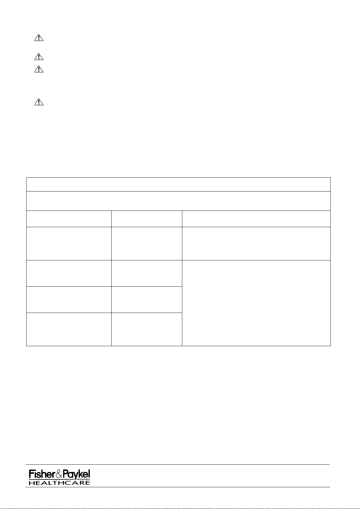
Guidance and manufacturer’s declaration – electromagnetic emissions
The IW900 series warmers are intended for use in the electromagnetic environment specified below. The
customer or the user of an IW900 series warmer should assure that it is used in such an environment.
Emissions test Compliance Electromagnetic environment - guidance
RF emissions
CISPR 11
RF Emissions
CISPR 11
Harmonic Emissions
IEC 61000-3-2
Voltage fluctuations/ flicker
emissions
IEC 61000-3-3
Group 1
Class A
Class A
Complies
The IW900 series warmer uses RF Energy only for
its internal function. Therefore, its RF emissions are
very low and are not likely to cause any interference
in nearby electronic equipment.
The IW900 series warmers are suitable for use in all
establishments other than domestic and those
directly connected to the public low voltage power
supply network that supplies buildings used for
domestic purposes.
IW900 Series Service Manual
Manufactured Before June 2008
PART NUMBER :
ISSUE DATE :
ISSUE NUMBER :
PAGE :
185041130
November 2008
I
19
Page 20
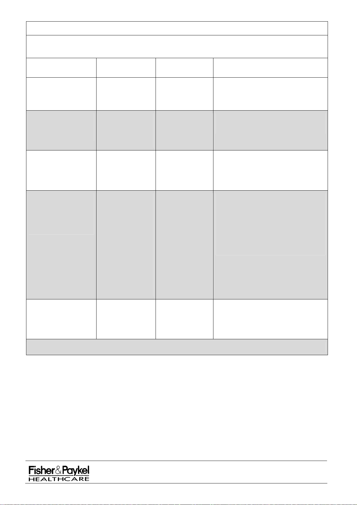
Guidance and manufacturer’s declaration – electromagnetic immunity
The IW900 series warmers are intended for use in the electromagnetic environment specified below. The
customer or the user of an IW900 series warmer should assure that it is used in such an environment.
IMMUNITY test
Electrostatic discharge
(ESD)
IEC 61000-4-2
Electrical fast
transient/burst
IEC 61000-4-4
Surge
IEC 61000-4-5
Voltage dips, short
interruptions and
voltage variations on
power supply input lines
IEC 61000-4-11
IEC 60601 test
level
± 6 kV contact
± 8 kV air
± 2 kV for power
supply lines
± 1 kV for
input/output lines
± 1 kV line(s) to
line(s)
± 2 kV line(s) to
earth
<5 % UT
(>95 % dip in UT)
for 0,5 cycle
40 % UT
(>60 % dip in UT)
for 5 cycles
<70 % UT
(>30 % dip in UT)
for 25 cycles
<5 % UT
(>95 % dip in UT)
for 5 s
Compliance level
± 6 kV contact
± 8 kV air
± 2 kV for power
supply lines
± 1 kV for
input/output lines
± 1 kV differential
mode
± 2 kV common
mode
<5 % UT
(>95 % dip in UT)
for 0,5 cycle
40 % UT
(>60 % dip in UT)
for 5 cycles
<70 % UT
(>30 % dip in UT)
for 25 cycles
<5 % UT
(>95 % dip in UT)
for 5 s
Electromagnetic environment -
guidance
Floors should be wood, concrete or
ceramic tile. If floors are covered with
synthetic material, the relative humidity
should be at least 30%.
Mains power quality should be at least
that of typical commercial or hospital
environment.
Mains power quality should be that of a
typical commercial or hospital
environment.
Mains power quality should be that of a
typical commercial or hospital
environment. If the user of the IW900
series warmer requires continued
operation during power mains
interruptions, it is recommended that the
IW900 series warmer be powered from
an uninterruptible power supply or a
battery.
Power frequency
3 A/m 3 A/m Power frequency magnetic fields should
(50/60 Hz) magnetic
field
IEC 61000-4-8
Note UT is a.c. the mains voltage prior to application of the test level
IW900 Series Service Manual
Manufactured Before June 2008
be at levels characteristic of a typical
location in a typical commercial or
hospital environment.
PART NUMBER :
ISSUE DATE :
ISSUE NUMBER :
PAGE :
185041130
November 2008
I
20
Page 21
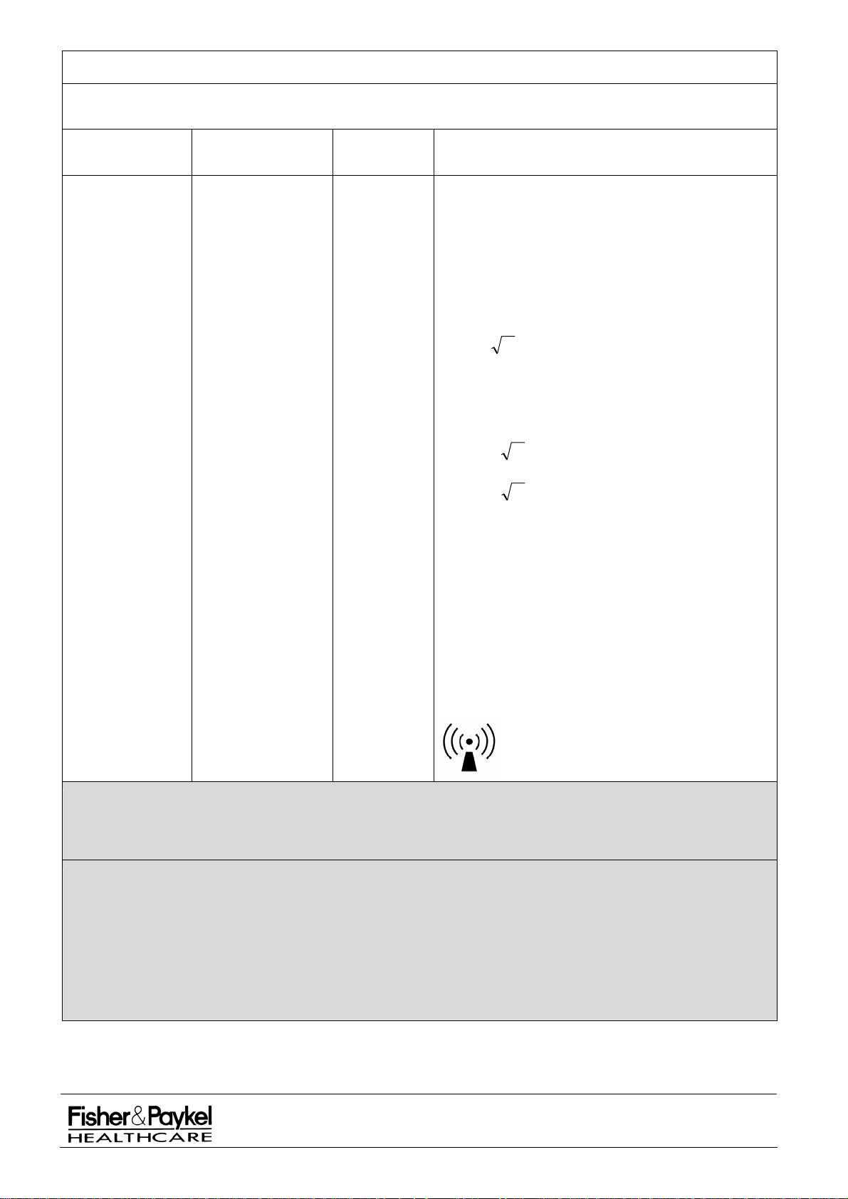
Guidance and manufacturer’s declaration – electromagnetic immunity
The IW900 series warmers are intended for use in the electromagnetic environment specified below. The
customer or the user of an IW900 series warmer should assure that it is used in such an environment.
IMMUNITY test
Conducted RF
IEC 61000-4-6
Radiated RF
IEC 61000-4-3
IEC 60601 test
level
3 Vrms
150kHz to 80 MHz
3 V/m
80 MHz to 2,5 GHz
Compliance
level
3 V
10 V/m
Electromagnetic environment - guidance
Portable and mobile RF communications equipment
should be used no closer to any part of an
series warmer
, including cables, than the
IW900
recommended separation distance calculated from
the equation applicable to the frequency of the
transmitter.
Recommended separation distance
Pd 2.1
Pd 35.0
80 MHz to 800MHz
Pd 70.0
800 MHz to 2,5 GHz
where P is the maximum output power rating of the
transmitter in watts (W) according to the transmitter
manufacturer and d is the recommended separation
distance in metres (m).
Field strengths from fixed RF transmitters, as
determined by an electromagnetic site survey,
should be less than the compliance level in each
frequency range.
b
Interference may occur in the vicinity of equipment
marked with the following symbol:
a
NOTE 1 At 80 MHz and 800MHz, the higher frequency range applies.
NOTE 2 These guidelines may not apply in all situations. Electromagnetic propagation is affected by
absorption and reflection from structures, objects and people.
a
Field strengths from fixed transmitters, such as base stations for radio (cellular/cordless) telephones and
land mobile radios, amateur radio, AM and FM radio broadcast and TV broadcast cannot be predicted
theoretically with accuracy. To assess the electromagnetic environment due to fixed RF transmitters, an
electromagnetic site survey should be considered. If the measured field strength in the location in which
an IW900 series warmer is used exceeds the applicable RF compliance level above, the IW900 series
warmer should be observed to verify normal operation. If abnormal performance is observed, additional
measures may be necessary, such as re-orienting or relocation the IW900 series warmer.
b
Over the frequency range 150 kHz to 80MHz, field strengths should be less that 3V/m.
IW900 Series Service Manual
Manufactured Before June 2008
PART NUMBER :
ISSUE DATE :
ISSUE NUMBER :
PAGE :
November 2008
185041130
I
21
Page 22
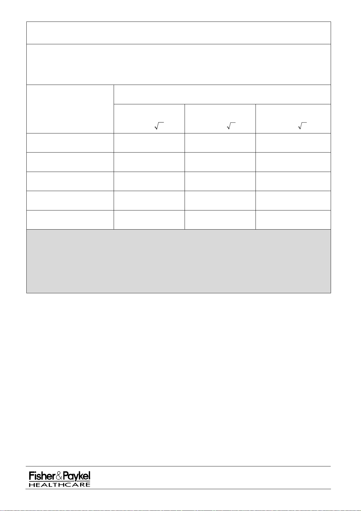
Recommended separation distances between portable and mobile RF
communications equipment and IW900 series warmers
The IW900 series warmers are intended for use in an electromagnetic environment in which radiated RF
disturbances are controlled. The customer or the user of the IW900 series warmers can help prevent
electromagnetic interference by maintaining a minimum distance between portable and mobile RF
communications equipment (transmitters) and an IW900 series warmer as recommended below, according to
the maximum output power of the communications equipment.
Separation distance according to frequency of transmitter
m
Rated maximum output power
of transmitter
W
150 kHz to 80 MHz
Pd 2.1
80 MHz to 800 MHz
Pd 35.0
800 MHz to 2,5 GHz
Pd 7.0
0,01 0.12 0.035 0.07
0,1 0.38 0.11 0.22
1 1.2 0.35 0.70
10 3.8 1.1 2.2
100 12 3.5 7.0
For transmitters rated at a maximum output power not listed above, the recommended separation distance d in
metres (m) can be estimated using the equation applicable to the frequency of the transmitter, where P is the
maximum output power rating of the transmitter in watts (W) according to the transmitter manufacturer.
NOTE 1 At 80 MHz and 800MHz, the higher frequency range applies.
NOTE 2 These guidelines may not apply in all situations. Electromagnetic propagation is affected by
absorption and reflection from structures, objects and people.
IW900 Series Service Manual
Manufactured Before June 2008
PART NUMBER :
ISSUE DATE :
ISSUE NUMBER :
PAGE :
185041130
November 2008
I
22
Page 23

Intentionally Blank
IW900 Series Service Manual
Manufactured Before June 2008
PART NUMBER :
ISSUE DATE :
ISSUE NUMBER :
PAGE :
185041130
November 2008
I
23
Page 24

PART 3: Maintenance and Servicing
WARNING
All maintenance should be undertaken by qualified service personnel.
3.1 Maintenance Schedule
Fisher and Paykel Healthcare recommend that the following Safety, Performance and Functional checks
be performed at least annually for all models covered by this manual. It is important to follow hospital and
local regulations if more frequent checks are stipulated.
NOTE: A maintenance check sheet is provided in 3.7.
Equipment
Depending on the extent of the service check and the accessories included on your
warmer the following
equipment may be required.
Safety Analyser: IEC60601-1 to class BF
Thermometer: 30 – 40C 0.1C
Pressure Gauge: 0 – 100psi 5% fsd
Pressure Gauge: 0 – 100cm H
0 2% fsd
2
Flowmeter: 0 – 15 L/min 5% fsd
Suction gauge: 0 – 200 mm Hg 2.5% fsd
Test Lung:
Calibrated Voltmeter
All electronics are calibrated during manufacture. Regular calibration is not necessary. A check of
calibration is included in the Performance Check.
3.2 Safety Check
WARNING Connect the power cord only to a properly grounded wall receptacle that is approved for
hospital use and of the correct voltage. DO NOT use extension cords or an AC receptacle box for
this device.
The unit should be tested to the current medical electrical standards for in-house testing for each
specific country (example, refer to UL2601-1 for USA, EN60601-1 for Europe, AS/NZS 3551 for
Australia and New Zealand). This should be done prior to initial use and at least annually thereafter.
NOTE: To conduct an earth test, the test lead should be attached to a bolt located under a plastic cap at the top of
the column – refer diagram 6.2.2 part 5.
NOTE: The Transport Handle is not earthed
but is protected in accordance with clause 17a)3) of IEC60601-1. To
verify safety conduct a Patient Leakage Current Test under normal operating conditions. The pass criterion
is less than 0.01 mA DC or 0.1 mA AC.
NOTE: The Medela Phototherapy Unit is double insulated. To verify safety conduct a Patient Leakage Current Test
on the metal arm under normal operating conditions. The pass criterion is less than 0.01 mA DC or 0.1 mA
AC.
NOTE: For neoBLUE-mini phototherapy refer to 185043921 service manual
IW900 Series Service Manual
Manufactured Before June 2008
PART NUMBER :
ISSUE DATE :
ISSUE NUMBER :
PAGE :
185041130
November 2008
I
24
Page 25

3.3 System Check
This procedure is the recommended performance check for Fisher & Paykel Radiant Warmers. A check
of calibration is included.
ALARMS CHECK
POWERFAIL CHECK
STUCK BUTTON
CALIBRATION CHECK
1. Switch the Power Switch on. Check that the increasing pitch start up sound occurs
and that the following alarm indicators, depending on the model, flash momentarily:
Check Baby, High Temperature, Low Temperature, and Sensor Disconnect
depending on model.
2. Unplug the power cord from the wall supply socket. Check that the Power Fail
Indicator flashes and audible alarm sounds.
3. Press and hold Prewarm/Standby Button. Reconnect the power cord to the wall
supply. Check that the warmer starts correctly and that the See Manual indicator
flashes and audible alarm sounds. Release the Prewarm/Standby Button.
NOTE: This check causes a Stuck Button error to occur which will be logged as the last
error that occurred as accessible via Information Mode.
4. Switch the Power Switch off then on again. Check that the warmer starts up
normally.
5. Enter Information Mode (refer section 2.5) and select EIN #5.
6. Ensure that the light is off. Measure the mains voltage at the wall outlet supplying the
warmer, using a calibrated voltmeter.
7. Calculate and record the measured voltage as a percentage of the devices nominal
supply voltage which will be 100V, 120V or 230V.
8. Check that the top display reads the calculated percentage (± 5%).
9. Select EIN #4.
10. Check that the top display reads 3950 ± 20 (39.50 ± 0.2°C). Exit Information Mode.
LIGHT CHECK
POWER MODE CHECK
TIMER MODE CHECK
HEATER CONTROL
TEMPERATURE
MEASUREMENT
11. Press the Light Button, check the light turns on. Re-press the Light Button and
check that the light turns off.
12. Press each power mode button (Prewarm, Manual, Baby if applicable) and check
that its respective indicator is lit when the button is pressed.
13. Ensure that the Timer Display is blanked. Press the Apgar Button and check that
the Apgar Indicator is lit and the time display starts counting. Press the Timer 1
Button and the Timer 2 Button in turn and check that the corresponding preset time
for each appears on the Timer Display and that the time starts counting down.
14. For all models:
Select Manual Mode and set the output power level to 0% (all segments of the power
bar are extinguished). Wait 1 minute and check that no heat is being given off by
the element. Set the output power level to 100% (all segments of the power bar are
lit).
15. For all models:
Check condition of skin sensor lead and sensor head.
Connect a skin sensor to the infant warmer and immerse the sensor end in water that
is warmed to a temperature in the range 35.0°C to 37.0°C. Use a calibrated
thermometer to check the temperature on the Skin Temperature Display is accurate
to within ± 0.2°C.
To check warmer calibration only - 043042566 check probe may be used, refer to
section 10.1.3
16.
Switch the Power Switch off.
IW900 Series Service Manual
Manufactured Before June 2008
PART NUMBER :
ISSUE DATE :
ISSUE NUMBER :
PAGE :
185041130
November 2008
I
25
Page 26

3.4 Functional Check
WARMER HEAD
Refer section 6.2.2.
MOBILE WARMERS
Refer section 6.3.2.
COSYCOTTM BASE
Refer section 8.1.4
ELECTRIC ELEVATOR
(If fitted)
Refer section 8.1.4
BASSINET MOUNTING
ASSEMBLY
If manufactured after February
2004 refer section 7.10
If manufactured before February
2004 refer section 7.12
TRANSPORT HANDLE
(If fitted) Refer to section 7.10
STORAGE DRAWER
(If fitted) Refer section 10.13
STORAGE BINS
(If fitted)
Refer section 10.14
GAS SUPPLY MANIFOLDS
(If fitted)
GAS HOSES
FLOWMETERS
(If fitted)
SUCTION
(If fitted)
UPS (UNINTERRUPTIBLE
POWER SUPPLY)
(If fitted)
MEDELA PHOTOTHERAPY
(If fitted)
1. Ensure the head is secure and that it can rotate smoothly. If required Head
Pivot Nut (1) can be adjusted using a bent wire tool (171042012). If the central
détente is not sufficiently positive, Washer Pivot (3) should be replaced.
2. Ensure everything is secure, in particular the stabiliser weight bolt (18) is tight
and that the pole (10) is fully engaged into the warmer support bracket (1) and
the stabiliser weight (13).
3. Ensure all four base to column bolts (11) are fully tightened 9-11.5Nm. Check
castors roll and lock.
4. Check operation of up/down buttons (28) and safety interlock rocker switch
(27). Inspect underside of base assembly for any sign of damage or wear.
Grease plastic/metal interface sections. Check arm pivot actuator for signs of
bending, replace using kit 043042714. Replace retention clips 625060035 as
necessary on vacuum formed base.
5. Ensure that the bassinet pivot bolts (5) and arm mounting bolts (19) are tight.
Check the operation of the tilt mechanism for smooth movement and no
slipping. Adjust actuation cable as outlined in section 3.6.8 if required.
6. Ensure all four M10 x 30 bolts (5), all four M8 x 50 CSK bolts (4) and all six M8
grub screws (2).are tight. Check the operation of the tilt mechanism for smooth
movement and no slipping. Adjust actuation cable as outlined in section 3.6.7 if
required.
7. Check operation of handle and release collars (4).
8. Ensure the drawer slides smoothly. If required clean and grease the sliders with
a food grade, non-drying grease.
9. Check that the bins rotate smoothly about the bin mounting pole (8) and that
the pole itself remains stationary. Ensure the two bin pole bolts (3) are tight and
that the bins are orientated in line with the bassinet when in the central détente
position.
10. Every six months the regulator output pressure (if fitted) should be verified with
an independent pressure gauge to ensure 50-60psi (344.7–413.7kPa) is
maintained. The adjustment procedure is detailed in section 9.2.2. Test for
leaks annually
using the procedure outlined in section 9.2.1.
11. Check for any visual signs of wear, damage or deterioration to the gas hose
and o-rings, and ensure there is no movement of crimped components away
from the hose. Exchange gas hoses as per national or hospital regulations and
guidelines.
12. Perform a visual operation check and flow test at 8LPM.
13. Refer to manufacturers manual for maintenance & servicing requirements.
14. Check operation, unplug from wall and check that it powers the warmer for >10
mins. Refer to the PowerVar UPS operating manual supplied with the unit for
maintenance, troubleshooting, and technical support.
15. Check whether the Lamp Replacement Warning Light is lit. Refer to section
11.1.6 to test the warning light. Replace
lamps if required referring to section
11.1.4. Check the cable is free from cuts and abrasions and the securing ‘P’
clip is intact. Check the grommet w
here the cable enters arm is in good
condition. Check the grille is firmly attached. Check that the head only swivels
when twisted by hand and does not turn of its own accord.
IW900 Series Service Manual
Manufactured Before June 2008
PART NUMBER :
ISSUE DATE :
ISSUE NUMBER :
PAGE :
185041130
November 2008
I
26
Page 27

3.5 Service Procedures- Replacement
Anti-Static procedures must be observed when handling printed circuit boards (PCB’s). Qualified
service technicians should carry out all servicing.
3.5.1 Replacement of Halogen Lamp.
If the warmer has been running then allow one hour for the heater and lamp to cool.
a.
b. Unplug the mains cable which supplies power to the unit. Turn off the UPS if installed
c. Unlatch the wire clips from the front of the head and remove the screw underneath the front of the
head which secures the lower case to the upper case. The rear screw will also need to be removed on
heads manufactured after August 2002.
d. Support the front of the head and pull both sides of the lower case down to open.
e. Pull the halogen lamp out. Using gloves to protect the new lamp, install by pushing into receptacle.
Use only 12V 20W 50 mm halogen lamps (Fisher and Paykel part # 424040069).
f. Close the lower casing of the head and replace the securing screws and wire clips.
g. Press the lower case along both sides to ensure it is clipped firmly into place.
3.5.2 Replacement of Controller Fuses.
Unplug the power cable from the wall supply outlet. Turn off the UPS if installed.
a.
b. Remove the four screws that secure the front control panel to the column (located behind the column).
c. Pull the front panel away from the column until the printed circuit boards are revealed.
d. Disconnect J12 (ribbon cable) from the control PCB. Disconnect J3 (ribbon cable) from the power
PCB. Disconnect J6 and J13 (power switch) from the power PCB. Remove the front panel.
e. Controller fuses F1, F2, F3, F4 and F5 are located on the power PCB. Replace as necessary.
f. Hold the control panel beside the column and reconnect connectors J12, J3, J6 and J13. .
g. Replace the front panel checking that it does not interfere with any wiring harnesses, in particular
ribbon cable (7) on controller assembly diagram 6.2.2
Replace the four screws.
h.
3.5.3 Replacement of Supply PCB Fuses (IW93x, IW95x, IW960 and IW970 models only
These include fuses for the Electric Elevator Module (if fitted), the Power Outlet (if fitted) and any
accessories that may be fitted. Refer to the photo in section 5.4.3 for fuse positions.
Unplug the power cable from the wall supply outlet. Turn off the UPS if installed.
a.
b. If 900IW403/405 Storage Bins are fitted these must be removed by unscrewing the eight M8x16
screws shown as part 5 in section 10.14.
Remove the four screws that secure the power inlet/outlet module to the column (located behind the
c.
column).
d. Supply PCB fuses F1, F2, F3, F4 and F5 are located on the back of the Inlet/Outlet Module. Fuse F4
is common to all of the accessories; fuse F1 is for the Electric Elevator Module, fuse F5 is for the
outlet socket and fuse F2 and F3 are for other accessories.
e. Replace the power inlet/outlet module including the four retaining screws.
f. Replace 900IW403/405 Storage Bins.
3.5.4 Replacement of Printed Circuit Boards.
Refer to photos in section 5.4 for PCB component identification. PCB’s are not repaired, and
individual electronic components
are not available. Replacement PCB’s are available – refer to
section 5.4 for spare part order numbers.
Carry out steps a. to d. of section 3.5.2.
a.
b.
To remove the control PCB from the front panel disconnect J2 (skin sensor) then release the plastic
clips beginning with the ones down the right hand side as viewed from the back.
c. To remove the power PCB from the column disconnect J8, J7, J10, J9 then remove phase and neutral
from J5. Unscrew the two 4mm self-tapping screws holding the heat sink to the column.
d. When replacing the power PCBs ensure it is securely held in the column extrusion groove on the right
hand side and by the two screws in the heat sink. Ensure that all of the 7 plastic clips/connectors on
the control PCB are secure.
e. When replacing the control PCB into the front panel, first remove the control knob (from the front
panel) so that it can be re-aligned to the rotary encoder on the control PCB afterwards.
)
IW900 Series Service Manual
Manufactured Before June 2008
PART NUMBER :
ISSUE DATE :
ISSUE NUMBER :
PAGE :
185041130
November 2008
I
27
Page 28
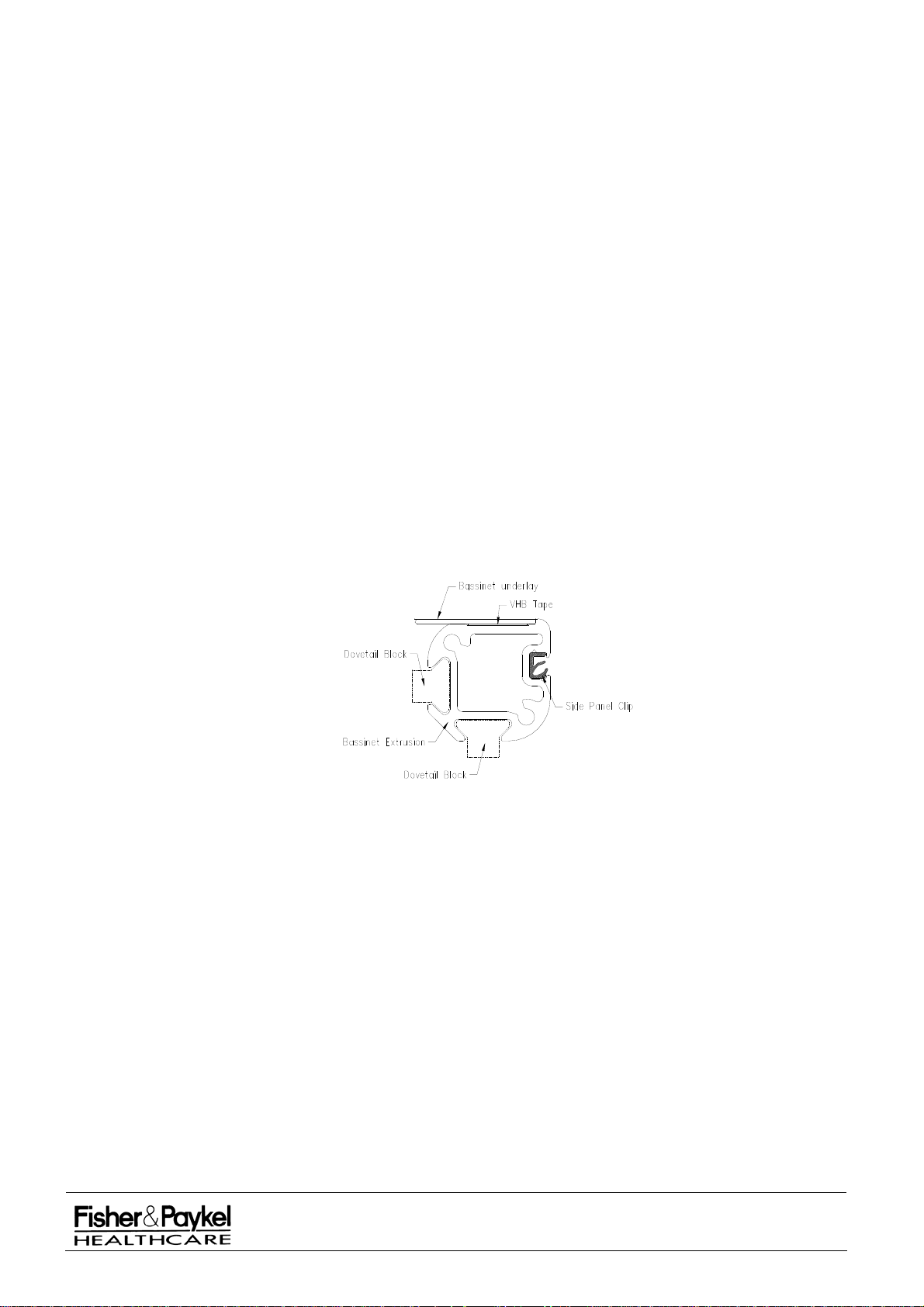
3.5.5 Replacement of Balance spring (IW910 and IW920 models only)
a. Unscrew plastic locking nut on adjustable pole, and remove upper pole with heater and controller.
b. Remove spring from lower pole.
c. Replace spring and refit upper pole.
3.5.6 Replacement of Castors (IW910 and IW920 models only)
a.
Grip castor and pull out of mobile base.
b. Push new castor home into castor hole.
3.5.7 Replacement of Castors (IW93x and IW95x models only)
a.
Lock castor and unscrew from leg.
b. Lock new castor and screw into leg ensuring that the circlip security plate (39) remains positioned over
the circlip (14) (refer diagram 8.1.4).
3.5.8 Replacement/ Addition of Acetal Side Panel Clips (Cosy
version 2.5 only)
Please refer to section 7.6 for part reference details.
a. Follow
section 3.5.9 to remove the left-hand corner cap from the side of the
changes are to be made.
b. Ensure that the Acetal Side Panel Clip(24) is the correct way up and slide the required number into
the rectangular gap located on the inside of the Corner Block (3), positioning it into the groove of the
bassinet extrusion.
c. Slide the Side Panel Clip along the Bassinet Extrusion (4) until in the desired location. To access all
four sides, all four Corner Caps will need to be removed. Reassemble Corner Cap in reverse order.
NOTE: Too many clips may result in unnecessary force and therefore potential damage to the side panel.
To meet IEC 60601-2-21 regulations at least two Acetal clips should remain on each side of the
bassinet.
Cot™ models with bassinets prior to
bassinet on which
Correct Orientation of the Acetal Side panel Clip (693041413)
IW900 Series Service Manual
Manufactured Before June 2008
PART NUMBER :
ISSUE DATE :
ISSUE NUMBER :
PAGE :
185041130
November 2008
I
28
Page 29

3.5.9 Replacement of Bassinet Corner Caps (IW93x, IW95x, IW960 & IW970 models only)
Refer to Bassinet Assembly diagram 7.3.2
a.
Remove all relevant side panels. Unscrew bolt (17) using a 5mm Allen key. For the front two corners
the rear handle (10) should be removed from each corner prior to unscrewing bolt (17).
b. When fitting a replacement plastic corner cap (694042167), ensure the two lugs locate under the top
surface of the corner block (3). Tighten bolt (17) to a torque of 3Nm.
c. Replace rear handle (10).
NOTE: For version 2.5 and version 3.0 bassinets the corner cap part number is 694042167.
For version 2.1 bassinets the corner cap part number is 694042134
For version 2.0 and 1.0 bassinets the corner cap part number is 641040819
3.5.10 Upgrading of Corner Cap Dummy Axles - (CosyCot™ models with bassinets prior to version 2.5
)
only
Refer to section 7.2.1 for details of the dummy axle change history. It is advised to replace the corner
cap bushes (653040121) at the same time as exchanging dummy axles. The
side panel sliding axle
will need to be upgraded at the same time as the dummy axle to ensure correct operation. Refer to
section 7.2.1 for the correct dummy axle and sliding axle combinations.
PART 3:
PART
Follow steps a – c in section 3.5.9 to remove the corner cap.
4: Slide out the two dummy axles in each corner cap and remove the urethane bushes with a pair
of pliers.
PART 5: Push a bush halfway into the corner cap before inserting the dummy axle. A thin smear of a
silicon grease should be applied to each oval axle stem prior to insertion.
3.5.11 Upgrading of Side Panel Sliding Axles
Refer to s
ection 7.2.1 for details of the sliding axle change history. The sliding axles were modified in
February 2001 to accept the lengthened dummy axles.
with all versions of dummy axle. If you have an earlier version of the side panels then the sliding axles
will need to be changed if they are to be fitted to a new version dummy axle.
a. Remove each side panel from the bassinet
b. Push one of the two sliding axles back to expose the grub screw which retains it. Using a 1.5mm Allen
key remove the grub screw and slowly release the sliding axle.
NOTE: The spring force could eject the sliding axle out of the extrusion if it is not securely held.
c. Repeat step b on the other sliding axle and discard both sliding axles.
d. Replace with one of the new sliding axles and use Loctite 272 to secure the grub screw back into the
extrusion. Do not wind the grub screw fully in; at least 1mm should be left exposed to ensure the
sliding axles are trapped in the slot.
e. Replace the spring and then carefully push the second sliding axle in place and reinstall the grub
screw using Loctite 272.
All side panels made after this date will work
IW900 Series Service Manual
Manufactured Before June 2008
PART NUMBER :
ISSUE DATE :
ISSUE NUMBER :
PAGE :
185041130
November 2008
I
29
Page 30
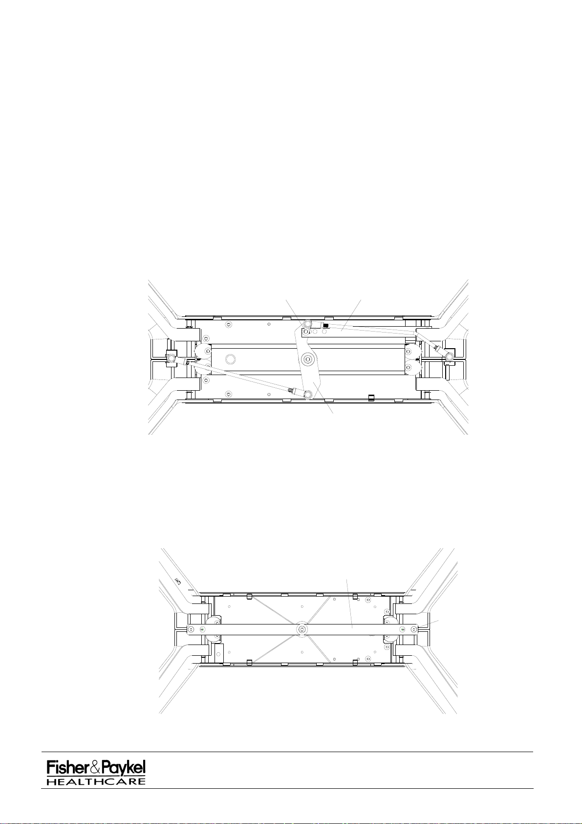
3.6 Service Procedures – Adjustment
3.6.1 Infant Warmer setup procedure for base servicing
3.6.1.1 Disconnect all power and gas from the warmer and remove UPS modules, Side shelves,
phototherapy lamps, gas cylinders and any other loose apparatus on the warmer.
3.6.1.2 Push the warmer from the front until the rear castors swivel round underneath the rear legs.
Lock the rear castors.
3.6.1.3 Stand behind the column and swing the head over to one side before carefully pulling the
warmer column towards you so that the entire warmer pivots on the locked rear castors. Pre-position
two chairs or stools in line with the column with one stool close to the base and gently lower the
column onto them so that the entire warmer rests on the back of the column and no weight is on the
base. Ensure the warmer cannot tip sideways when resting on the chairs/stools.
3.6.2 Pre-set Base Height Adjustment (IW93x and IW95x models w
For Warmers Manufactured before February 2004
Preset bases manufactured prior to Feubruary 2004 can have the bassinet height adjusted to 88.4,
97.5 or 101.9 cm (34.8”, 38.4” or 40.1”) by repositioning the lock bar. Refer to Figure 3.6.3 below.
Using a 17mm spanner and 6mm Allen key remove the M10 x 30 screw and Nyloc nut (1). Pull both
sets of legs together until the desired hole on the lock bar (2) lines up with the hole in the pivot arm
(3). Replace the M10 screw and Nyloc nut (1) and fully tighten.
1 2
3
TM
3.6.3 Figure of under side of preset CosyCot
warmer base Manufactured before February 2004
ith preset bases only)
For Warmers Manufactured after February 2004
Preset bases manufactured after February 2004 can have the bassinet height adjusted to 90.5 or
100.5 cm (35.6”or 39.6”). Refer to Figure 3.6.4 below. Using a 5mm Allen key remove the two M8x25
screws (2). Pull the legs together until the other set of holes on the base adjustment bar (1) line up
with the holes on the legs.Replace the M8 screw and fully tighten. There are only two adjustment
points for this system.
3.6.4 Figure of underside of preset CosyCot
1
2
TM
Warmer Base Manufactured after February 2004
IW900 Series Service Manual
Manufactured Before June 2008
PART NUMBER :
ISSUE DATE :
ISSUE NUMBER :
PAGE :
185041130
November 2008
I
30
Page 31

3.6.5 Base Level Adjustment (IW93x and IW95x models only)
NOTE: Required on warmers with electric elevator bases and preset bases manufactured preFebruary 2004. After this date a new preset system means that base level adjustment is not required.
If the base or column are not level, then adjustment of the straight tie rod is required. The straight tie
rod is located underneath the base between the centre pivot and the rear legs.
a. Undo the lock nut that secures the straight tie rod to the ball joints.
b. In the middle of the rod is a flat section that should be used for adjustment. Use the 6 mm
wrench (part of the tool kit) to turn the rod. One full clockwise turn of the rod (thread M8 x 1.25) will
lower the column down by approximately 4 mm. Hence, one full anti-clockwise turn of the rod will lift
the column end up by approximately 4 mm.
c. Adjust to level column and base.
d. Tighten the lock nut.
NOTE: When the rod is assembled, the ball joints remaining threaded portions are:
Leg side: 10 mm (full length is 20 mm)
Pivot side: 10 mm (full length is 25 mm)
CAUTION
A maximum of four full clockwise turns are allowed (remaining threaded portion 5 mm).
3.6.6 Castor Angle Adjustment (IW93x & IW95x models only
If the castor is not vertical to the floor, adjustment of the link arms is required. The link arms are
located underneath the leg. Castor angle cannot be adjusted on warmers after the above serial
number – refer to PART 12: for serial number identification.
Undo the lock nuts that secure the straight tie rod to the ball joints.
a.
b. In the middle of the arm are two holes spaced at 90°. Use a 3mm Allen key or a 3mm bar to
turn the arm. One full clockwise turn of the arm (thread M10 x 1.5) will move the castor
outwards by approximately 3 mm. Hence, one full anti clockwise turn of the arm will move the
castor inwards by approximately 3 mm.
c. Adjust the castor to the vertical position.
d. Tighten the lock nuts.
NOTE: When the arm is assembled the remaining threaded portions on both sides are 13 mm
(including 8mm thick lock nuts).
CAUTION
A maximum of ten full turns clockwise are allowed (thus the remaining threaded portion
will be 10 mm).
prior to serial No. 9795AEA00436)
IW900 Series Service Manual
Manufactured Before June 2008
PART NUMBER :
ISSUE DATE :
ISSUE NUMBER :
PAGE :
185041130
November 2008
I
31
Page 32

3.6.7 Bassinet Clutch Adjustment (IW93x, IW95x, IW960 & IW970 models only)
If the bassinet can be tilted without actuating the rear handle, or pulling the two handles together
doesn't allow tilting of the bassinet, then the bassinet tilt clutch requires adjustment.
Adjustment is performed with the adjuster screw (for fine alterations) or by moving the cable support
block (for coarse alterations).
If Bassinet Clutch is too tight (i.e. bassinet can not be tilted):
a. Loosen lock nut on adjuster screw and wind screw out. If screw is already fully wound out then
cable support block will have to be moved.
b. Use a 4mm ball ended Allen key to loosen the two grub screws securing the cable support
block to the bassinet frame.
NOTE: On version three bassinets (manufactured from November 2002) a single M8 cap screw has
replaced the two grub screws, a 5mm Allen key is required to loosen this screw.
c. Wind the adjuster screw approximately half way out.
d. Butt the adjuster screw against the cable sheath by sliding the cable support block towards the
rear of the warmer.
e. Fix the cable support block in position by tightening the two grub screws.
f. Move the bassinet tilt brake handle backwards as far as it will go and wind adjuster screw out to
take up tension.
g. Tighten adjuster screw lock nut.
h. Pull the bassinet rear handle forwards and check brake release operation.
If Bassinet Clutch is too loose (i.e. bassinet can be tilted without using the bassinet handles):
a. Loosen lock nut on adjuster screw and wind screw in. If screw is already fully wound in then
cable support block will have to be moved.
b. Use a 4mm ball ended Allen key to loosen the two grub screws securing the cable support
block to the bassinet frame.
NOTE: On version three bassinets (manufactured from November 2002) a single M8 cap screw has
replaced the two grub screws, a 5mm Allen key is required to loosen this screw.
c. Wind the adjuster screw approximately half way in.
d. Follow steps d to h above.
If the clutch is still loose the actuator spring can be tightened. Referring to diagram in section 7.12;
using a ball ended 4mm Allen key on the M5 screw (part 15) and a 6mm open spanner on the
actuator (part 12) tighten the spring by winding the screw in. The 12mm washer (part 16) should
coincide with a line on the lower tilt link molding (part 7). Cleaning the tilt brake sliders (part 10) with
alcohol to remove any particles can also improve the clutch performance.
3.6.8 Bassinet Brake Adjustment (For CosyCot
system)
If the bassinet can be tilted without actuating the rear handle, or pulling the two handles together
doesn't allow tilting of the bassinet, then the bassinet brake requires adjustment.
Adjustment is performed with the adjuster screw on the cable:
a. Move the bassinet so that the handle is in the lowest position
b. Loosen the lock nut on the adjuster screw.
c. Wind the screw such that there is 2mm of play in the lower handle (winding it out will reduce the
play).
d. Tighten the adjuster screw lock nut.
brass
TM
's manufactured after Feb. 2004 with the toothed brake
IW900 Series Service Manual
Manufactured Before June 2008
PART NUMBER :
ISSUE DATE :
ISSUE NUMBER :
PAGE :
185041130
November 2008
I
32
Page 33
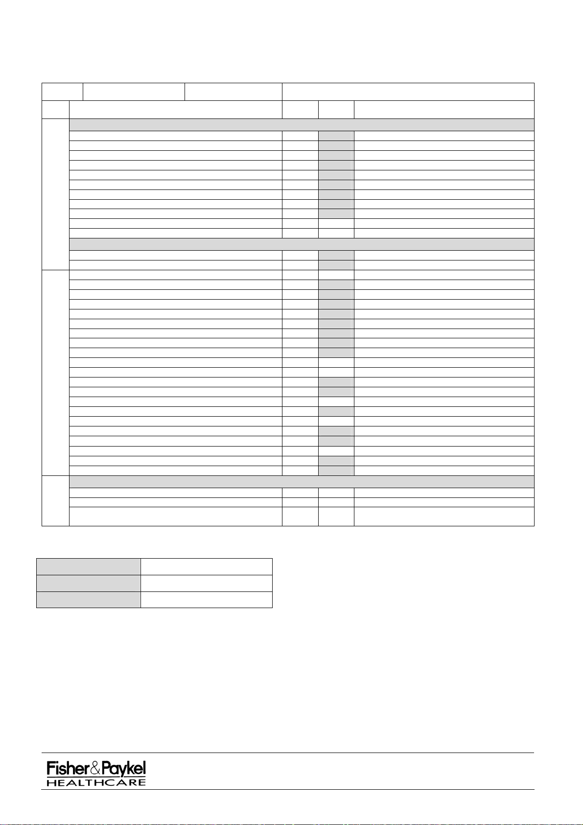
3.7 Recommended Maintenance Checklist
This sheet can be copied and used to keep a record of the maintenance procedures carried out on your Fisher &
Paykel Healthcare 900 series Infant Warmer.
Model IW Serial number
Checks Required Resu lt Units Detail
System Checks
Alarm indicator check
Power fail alarm check
Stuck button check
Calibration Check EIN #5 value within ± 5 of calculated percentage
Calibration Check EIN #4 3950 ± 20
Light check
Power mode check
Timer mode check
Heater control No heat 100% heat Segments
Temperature measurement check
Warmer calibration test using check probe (if available)
Functional Checks
Mobile & Wallmount & Cosycot
Head pivot securing nut check
Security of stabiliser weight bolt (mobile only) Spring washer fully deformed
Security of column bolts Nm 12-14 Nm
Check castors roll & lock & are fully screwed into base
Check all circlips present in base
Electric elevator check
Arm pivot actuator check No bending evident
Bassinet mounting check Ensure bolts are secure & tilt mechanism secure
Transport handle check (as fitted)
Storage drawer check (as fitted)
Storage bins check (as fitted)
Gas Supply Module regulator output pressure OXYGEN psi 60±5 psi (414±34kPa) {50±5psi USA}
Gas Supply Module regulator Output AIR psi 60±5 psi (414±34kPa) {50±5psi USA}
Gas Supply Module leak check OXYGEN No cylinder gauge movement in 15 mins
Cosycot
Gas Supply Module leak check AIR No cylinder gauge movement in 15 mins
Other low pressure gas accessories leak check psi < 4 psi in 15 minutes
Gas Hoses
Flowmeters accuracy - test flowmeter at 8 LPM LPM 7.5 - 8.5 LPM
Suction check Refer to suction device documentation
Neopuff
UPS run time check mins > 8mins
Phototherapy lamp output check Refer to phototherapy lamp documentation
Low flow microblender checks Refer to microblender documentation
Electrical Safety
Earth Resistance Ω As per IEC 62353 ( < 200mΩ)
Earth Leakage μA As per IEC 62353 ( < 500μA)
All
Patient Applied Path Leakage
(900IW001/900IW003/NC020)
μA As per IEC 62353 ( < 5000μA)
O
C ± 0.2OC of test water temperature
O
C 36.7 ± 0.1OC
Refer to Neopuff™ Service Manual 185041597
Technician
Technician Signature
Date
IW900 Series Service Manual
Manufactured Before June 2008
PART NUMBER :
ISSUE DATE :
ISSUE NUMBER :
PAGE :
185041130
November 2008
I
33
Page 34
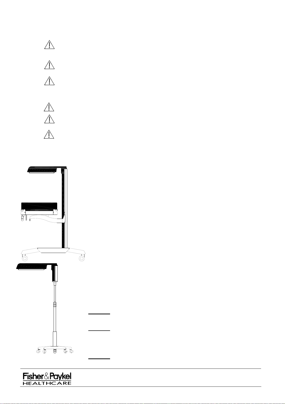
PART 4: Cleaning
WARNING
To avoid the possibility of burns when performing cleaning procedures, ensure the Infant
Warmer is disconnected from the power supply and the heater element is allowed to cool
for one hour, or until cool to the touch.
To avoid the possibility of electric shock hazard when performing cleaning procedures,
ensure the Infant Warmer is disconnected from the power supply.
If the 900IW505x Battery Module is installed on the CosyCot™ Infant warmer, please
ensure the 900IW505x Battery Module is powered off prior to cleaning. Do not remove the
900IW312x Battery Module Shroud during cleaning procedures. Ensure no part of the
900IW505x Battery Module is immersed in any cleaning agent.
Do not allow cleaning liquids or cleaning solutions to enter into electrical housings.
Do not allow cleaning liquids or cleaning solutions to collect around or enter into oxygen
or air fitting.
Ensure all oxygen and air supplies are turned off and disconnected from the CosyCot™
Infant Warmer before performing cleaning procedures. Explosion and fire hazards can
exist when performing cleaning procedures in an oxygen-enriched environment.
4.1 General Cleaning
Clean the Infant Warmer and accessories either weekly or
between patients using the following cleaning procedures:
Comply with hospital, local and national guidelines for product cleaning
frequencies.
Cleaning shall be performed at ambient conditions. Allow heated surfaces to
cool for at least one hour or cool to the touch before cleaning.
Before cleaning, remove and discard all used disposable products using the
recommended method of disposal.
Dust all surfaces with a clean damp soft cloth.
Clean all plastic surfaces with detergent based solution (maximum 2% in water)
ensuring the manufacturer’s directions for use of the cleaning agent are
followed.
The plastic surfaces highlighted in black contain plastic components made
from polycarbonate or acrylic, and include the entire heater assembly, bassinet
side panels, column cap and front panel fascias.
The following proprietary chemical cleaning wipes (and their manufacturer) are
recommended if the highlighted plastic surfaces require cleaning for infection
control purposes.
Caviwipes (Metrex Research Corporation)
Sani-cloth HB (Professional Disposables, Inc.)
Asepti-Wipes II (Ecolab, Inc.)
Dry all surfaces after cleaning with a clean soft cloth or paper towel.
CAUTION
Ensure no part of the Infant Warmer or related accessories
is immersed in any cleaning liquid or cleaning solution.
CAUTION
Do not clean the infant radiant warmer heating element.
NOTE: The recommended chemical cleaning wipes listed above have been
checked for long term compatibility with the IW900 Series Infant Warmers.
CAUTION
Do not clean the highlighted plastic surfaces with proprietary cleaning
products containing either hydroxides, hypochlorites, peroxides,
IW900 Series Service Manual
Manufactured Before June 2008
PART NUMBER :
ISSUE DATE :
ISSUE NUMBER :
PAGE :
185041130
November 2008
I
34
Page 35

gluteraldehyde or cleaning products with a greater than 30% alcohol
base.
CAUTION
The chemicals used in these proprietary cleaning products may lead
to discolouration, crazing and eventual cracking of the highlighted
plastic surfaces.
Examples
of proprietary cleaning products which contain such cleaning chemicals
include but not limited to:
Asepti-Wipes (Ecolab, Inc)
Clorox (The Clorox Company)
Endbac 256 (Johnson Wax Professional)
Quat (3M)
Sporiciden (Liberty Industries, Inc)
Sporox II (Sultan Healthcare)
Steris (Steris Corporation)
Terralin (Schülke & Mayr)
Virtek (A Virtek Company)
Virox (Virox Technologies)
CAUTION
CAUTION
Do not use abrasive cleaning solutions.
Ensure all Infant Warmers and accessories are checked before returning
the Infant Warmer to service.
4.1.1 Skin Sensor Clean the skin sensor with alcohol, or
2%) in water), ensuring the manufacturer’s directions for use of the cleaning
agent are followed.
Apply the cleaning solution with a clean cloth or sponge, and dry all surfaces
after cleaning with a clean soft cloth or paper towel.
CAUTION
Do not autoclave or gas sterilise the skin sensor.
Do not pull on the sensor cup or sensor plug during cleaning or drying as
the skin sensor may be damaged.
Ensure the skin sensor is only removed from the controller by grasping
the plug at the front panel. Ensure excessive strain is not placed on the
sensor lead either during use, cleaning or inspection.
4.1.2 Mattress Clean the mattress with an
approved and correctly diluted disinfectantdetergent solution, ensuring the manufacturer’s directions for use of the
cleaning agent are followed.
Apply the cleaning solution with a clean cloth or sponge, and dry all surfaces
after cleaning with a clean soft cloth or paper towel.
CAUTION
Do not autoclave the mattress.
4.1.3 Sterilisation CAUTION
Do not autoclave or gas sterilise any part of the warmer
For cold sterilisation: Ensure the cold sterilisation agents are safe for use
with the relevant warmer surfaces.
Do not expose plastic and acrylic surfaces to direct radiation from
germicidal lamps. The ultraviolet radiation from these sources can cause
crazing and cracking.
detergent or soap solution (maximum
4.1.4 After cleaning CAUTION
Ensure all warmer parts and accessories are checked before
returning the device to service.
IW900 Series Service Manual
Manufactured Before June 2008
PART NUMBER :
ISSUE DATE :
ISSUE NUMBER :
PAGE :
185041130
November 2008
I
35
Page 36
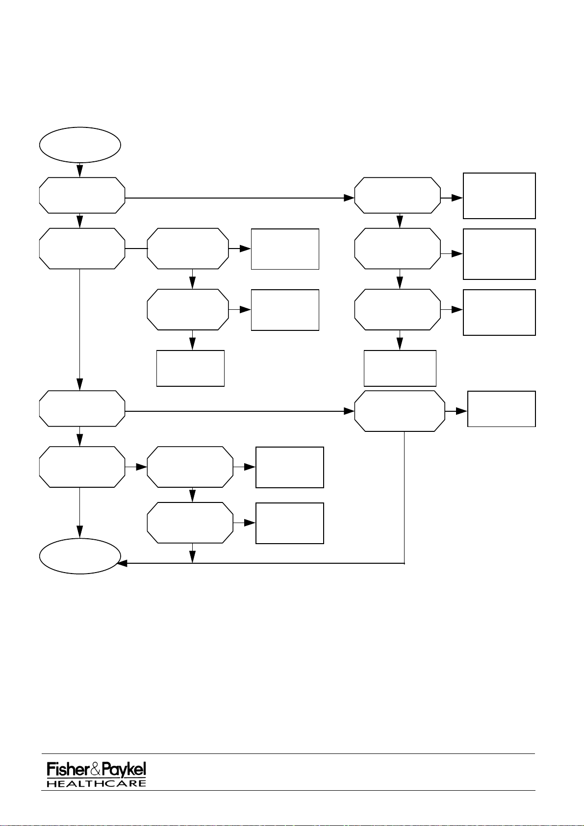
PART 5: IW900 Series Electronics
5.1 Troubleshooting Flow Chart
War mer
suspected faulty
See manual
alarm sounding?
No
Power fail
alarm flashing?
No
Yes Yes
Yes Yes
Wall outlet power
switch turned
off?
No
Switch on power
at wall outlet
See manual
indicator fl ashing?
No
See manual indicator
accompanied by constant
monotone alarm?
No
Software has detected
a fault. Use information
mode to obtain error
code. See Section 2.5.
Thermal cut-out in
head has switched
Yes
open circuit due to
overheat ing. Reset
thermal cut-out and
identify cause.
Skin temperature
reading inaccurate?
No
Unable to provide
stable control of skin
temperature when in
baby/patient mode?
No
Contact Fisher & Paykel
representative for
technical assistance
Check internal
fuses, mains lead and
internal harnesses.
Defective part?
No No
Replace power PCB
Yes Yes
Skin sensor is poorly
attached to patient or
heat path between patient
and element is disrupted?
No
Alarm is sounding and
mute butt on is not being
pressed?
No
Yes
Yes
Repl ace fu se or
defective part
Attach skin sensor
in correct position and
ensure there i s no
heat path disturbance
Press mute when
warmer alarms. This
ensures heat is
restored to patient
See manual indicator
accompanied by rapid
pulsing two tone alarm?
See manual alarm is
probably spurious.
Replace cont rol PCB.
Skin sensor is
damaged, not insert ed
fully, or not a twin bead
YSI 400 type?
No
Watchdog for micro
Yes
controller has detected
a fault in the control or
Replace def ective PCB.
YesYes
Replace skin sensor
power PCB.
IW900 Series Service Manual
Manufactured Before June 2008
PART NUMBER :
ISSUE DATE :
ISSUE NUMBER :
PAGE :
185041130
November 2008
I
36
Page 37
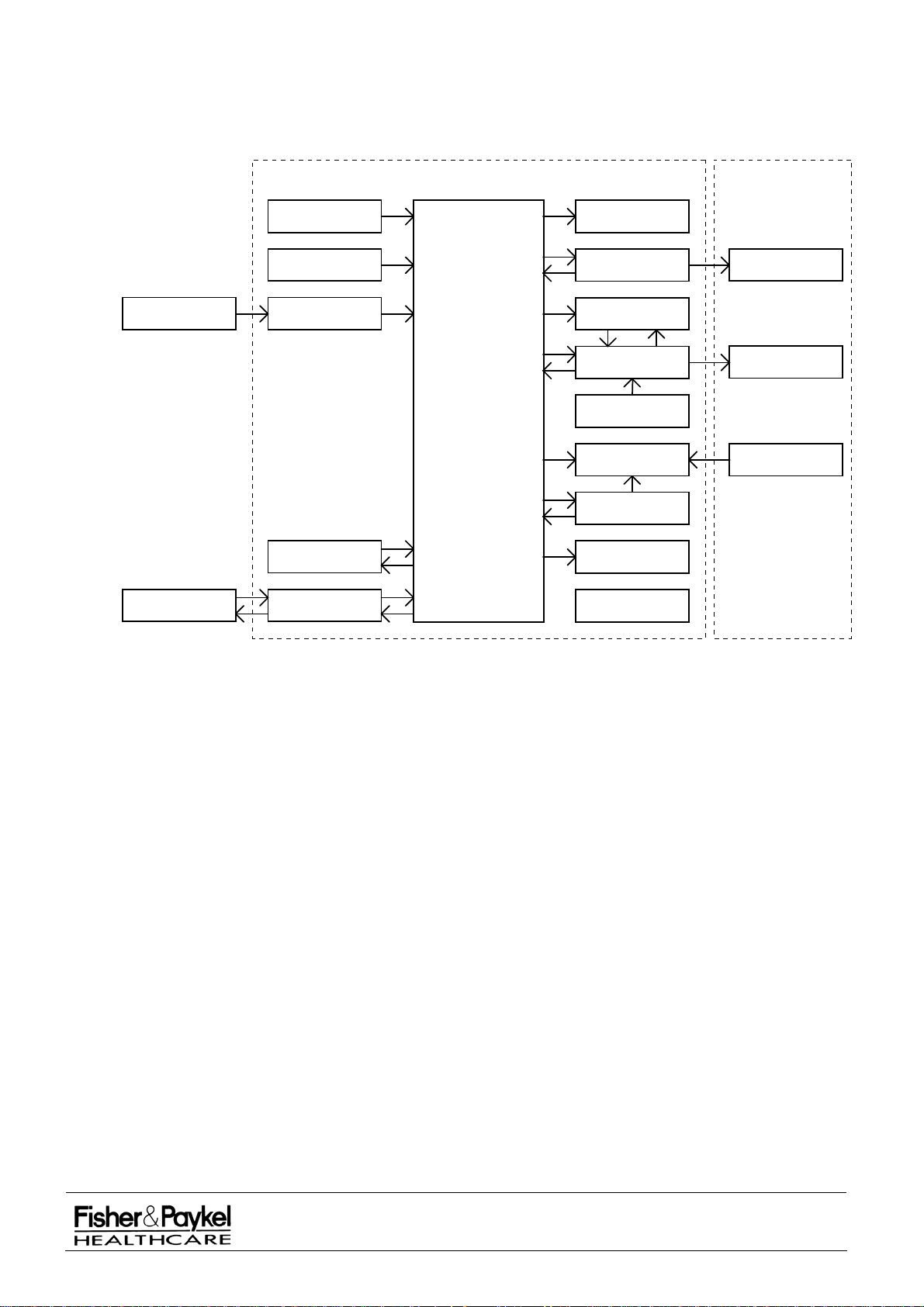
5.2 Circuit Overview
Figure 6.2 gives an overview of the IW900 series controller electronics. The location of major components
and connectors on the PCB's are shown in Section 5.4. Full schematics are given in Section 5.5.
Controller Heater
Patient
Remote
Device
Buttons and
Control Knob
Zero Crossing and
Voltage Level Sense
Temperature
Measurement
EPROM and
EEPROM
RS232
Communications
Microcontroller
Displays and
Indicators
Light Control
and Sense
100% Output
MonitorProbe
Heater Control
and Sense
OverTemperature
Comparator
See Manual
Alarm
Watchdog and
Reset Oscillator
Pitch and Volume
Controlled Buzzer
Power Fail
Alarm
Examination
Light
Heater and
Reflector Assembly
Thermostat
IW900 Series Controller Overview
The controller electronics are mounted behind the front control panel on two printed circuit boards (PCBs)
-
the Control PCB and the Power PCB (see section 5.4 for PCB component photos):
POWER PCB The power PCB provides power supply and I/O lines necessary for
sense and control of the examination light and heating element. It holds
the mains voltage parts and incorporates a heat sink. The power PCB
is connected to the control PCB by a single 14-way ribbon cable (J3).
Also connected to the Power PCB are the power transformer (J10 and
J9), the heater, light and thermal cut-out harness (J7 and J8), the power
switch (J13 and J6) and the mains input terminals (J5).
CONTROL PCB The control PCB is based around the Phillip’s 80C552 micro-controller.
It provides a user interface, temperature measurement and intelligent
control of the element power. Almost all of the warmer functions are
implemented in software. The control PCB is connected to the Power
PCB (J1), the skin sensor socket (J2) and the serial communications
port (J12).
IW900 Series Service Manual
Manufactured Before June 2008
PART NUMBER :
ISSUE DATE :
ISSUE NUMBER :
PAGE :
185041130
November 2008
I
37
Page 38

5.3 Circuit Description
5.3.1 Software Independent Safety Circuits
Five safety features are included which function independently of the micro-controller. These safety
features are provided in addition to the safety features already provided by the micro-controller software.
OVER TEMPERATURE COMPARATOR A comparator (U12B) is used to disable heat in the element if a skin
temperature exceeding 39.5°C is detected (see Performance Check
Procedure in Section 3.3). Under normal conditions the software will
not allow this to happen because a
will exist and the power will be reduced to 0%. If a fault prevents the
software alarm from occurring then this comparator will stop the microcontroller from applying power to the heater element. The microcontroller will then cause a See Manual alarm with error code 17
because it will sense that it can no longer control the heater.
100% OUTPUT MONITOR A counter circuit (U13) is used to detect when uncontrolled mains
voltage is applied to the heating element. It does this by counting how
many continuous mains pulses are supplied to the element. If this
count exceeds a threshold value then relays RL2 and RL3 will open
thereby disconnecting the element from the mains supply. Under
normal conditions the software will not allow this to happen. If this
circuit detects continuous full power in the element and opens the
relays then the software will detect it is unable to control the element
power and will show a See Manual alarm with error code 17.
WATCHDOG & RESET OSCILLATOR An external hardware watchdog is included which monitors activity of
the micro-controller. If the micro-controller is not regularly toggling the
watchdog pin, then a See Manual alarm will be started (see Section
2.4) and the micro-controller will be reset. Power to the element will be
disabled.
high temperature alarm condition
OVERHEAT THERMAL CUT-OUT Thermal cut-out (rated at 150°C) is fitted in the heater which will cause
power to be removed from the element in the event of overheating
(within the heater). If this thermal cut-out is tripped then relays RL2 and
RL3 will open thereby disconnecting the element from the mains supply
and a See Manual alarm will result (see Section 2.4).
POWER FAIL ALARM The energy stored in the super capacitor C22 provides up to 10 minutes
of pulsing alarm in the event that power fails while the unit is switched
on. The alarm sounds self-oscillating buzzer PZ2 and flashes the
power fail LED.
IW900 Series Service Manual
Manufactured Before June 2008
PART NUMBER :
ISSUE DATE :
ISSUE NUMBER :
PAGE :
185041130
November 2008
I
38
Page 39

5.3.2 Software Controlled Circuits
The remaining circuit components are used in conjunction with the micro-controller software:
MICRO-CONTROLLER
PROM AND EEPROM
U4 is a Phillip’s 80C552 which controls most aspects of the warmer.
U8 contains the micro-controller software and many non-volatile presets
are contained in U7. U7 can only be serviced by the manufacturer
because it contains factory preset information.
RS232 COMMUNICATIONS U6 provides an RS232 interface with the micro-controller. This is used
for manufacturing purposes only.
BUTTONS & CONTROL KNOB All user input is via the buttons or the control knob. The encoder
SW11 has a two-wire quadrature output that allows the micro-controller
to sense movement and direction. U2 and U3 multiplex the buttons into
a single line that is used as an input by the micro-controller.
DISPLAYS & INDICATORS U1 drives the displays and indicators which are configured in four
banks. A single line from U1 is used as feedback to the micro-controller
(test point TP9).
LIGHT CONTROL & SENSE Relay RL1 controls the examination light and U16 provides feedback on
the state of the light to the micro-controller.
HEATER CONTROL & SENSE Triac Q22 controls the power to the element. It is opto-isolated with
U15. Relays RL2 and RL3 allow the
WATCHDOG circuit to remove power from the element if a fault is
100% MONITOR circuit and the
detected. Current pulses in the element are sensed via coil T1 (test
point TP15).
PITCH & VOLUME CONTROL BUZZER U19 provides pitch and volume control over buzzer PZ1 which plays all
alarm and acknowledge sounds.
ZERO CROSSING & LINE LEVEL SENSE The mains voltage is monitored by a secondary winding from the power
transformer. Comparator U14E detects zero crossings and a waveform
is derived (found at test point TP14) which exhibits a momentary
negative going pulse on each zero crossing. A DC voltage proportional
to line voltage level is detectable at TP8.
IW900 Series Service Manual
Manufactured Before June 2008
PART NUMBER :
ISSUE DATE :
ISSUE NUMBER :
PAGE :
185041130
November 2008
I
39
Page 40
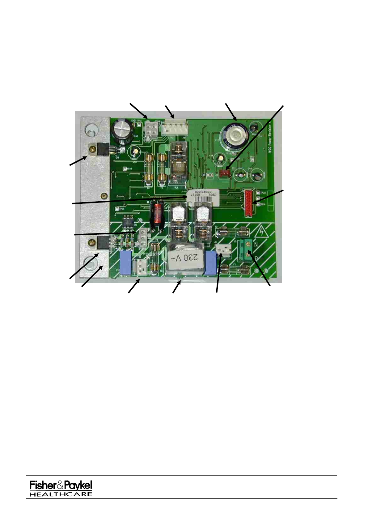
5.4 PCB Component Locations
(J9)
The photographs below identify some of the major components used on the IW900 series of Infant Radiant
Warmers and where they are located.
5.4.1 Power PCB Board
NOTE: These are voltage specific with the voltage identified by a label on the mains isolating relay.
5V
Regulator
PCB
Barcode
(from Aug
2002)
Power To
Heater
Element
(J7)
Light & Thermal
Cutout (J8)
12V From
Transformer
(J10)
Super
Capacitor
C22
Power
Fail Alarm
Switch
(J13)
Power to
Control
PCB Ribbon
Cable
(J3)
Triac
Heatsink
Mains
Power To
Transformer
Mains
Isolating
Relay
Main
Switch
(J6)
Mains Power
Screw Terminal
Block
The spare parts numbers for the Power PCB boards are listed below:
043041005
PCB Assy Power IW900 100V
043041004 PCB Assy Power IW900 120V
043041003 PCB Assy Power IW900 230V
311040682 SuperCap 1F 5.5V HT
999830009 Fuse 2A 250V fast blow 20x5mm
(F3 and F4 for all models)
348060023 Fuse 8A 250V fast blow 20x5mm
F5 for all models, F1 and F2 for 100V/120V models)
348060022 Fuse 4A 250V fast blow 20x5mm
(F1 and F2 for 230V models)
NOTE: 20x5mm fast blow fuses are available from standard electrical suppliers. The correct replacement
fuses are listed on the label inside the front panel.
IW900 Series Service Manual
Manufactured Before June 2008
PART NUMBER :
ISSUE DATE :
ISSUE NUMBER :
PAGE :
185041130
November 2008
I
40
Page 41
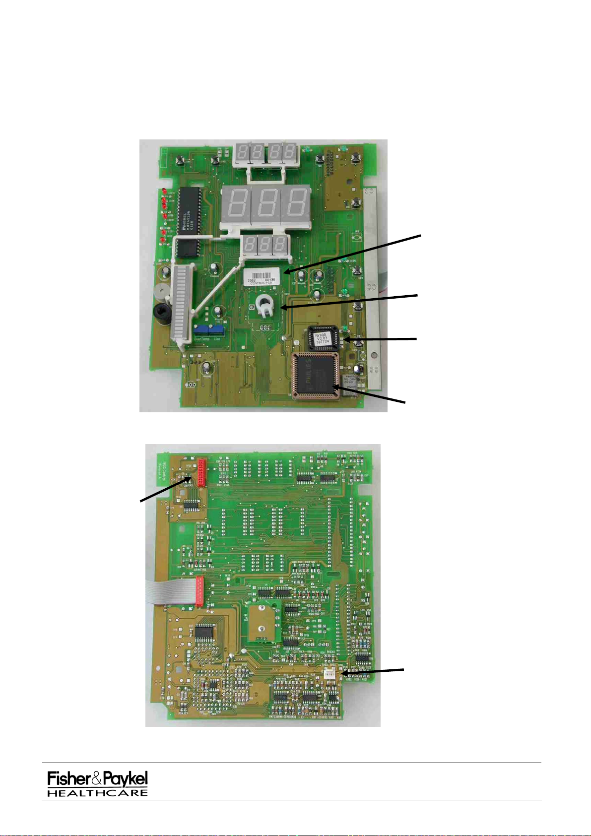
5.4.2 Control PCB Board
There are two different control PCBs depending on whether you have a Servo (Baby) controlled warmer or
a Manual warmer. The spare part numbers for ordering new Control PCB boards are:
For IW910, IW93x, IW960 and IW980 043041041 PCB Assy Control IW900 Servo
Servo controlled warmers:
For IW920, IW95x, IW970 and IW990 043041002 PCB Assy Control IW900 Manual
manual controlled warmers:
PCB Barcode
(from August
2002)
Control
Knob
Front View of IW900 Series Control PCB Board
RS232
Connector
(J12)
EEPROM
Microcontroller
DuoSense
Harness
Connector
(J2)
Rear View of IW900 Series Control PCB Board
IW900 Series Service Manual
Manufactured Before June 2008
PART NUMBER :
ISSUE DATE :
ISSUE NUMBER :
PAGE :
185041130
November 2008
I
41
Page 42
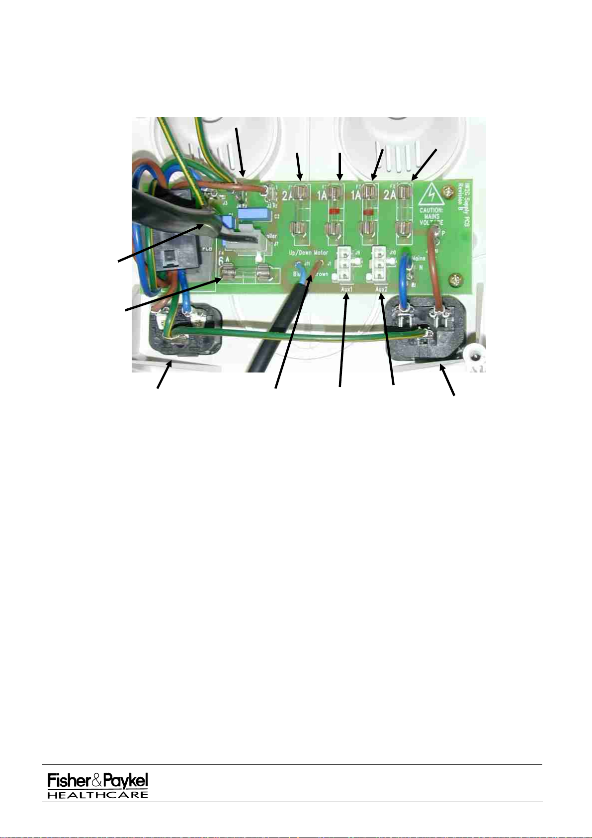
5.4.3 Power Supply PCB Board
This PCB is only used on IW93x, IW95x, IW960 and IW970 CosyCot™ warmers and is located in the
lowest module of the column. It is not voltage specific.
Warmer
Power
Supply
Mains Fuse
(F4)
Mains Spade
Connectors
Elevator
Fuse
(F1)
Aux1
Fuse
(F2)
Aux2
Fuse
(F3)
Mains
Outlet
Fuse
(F5)
Mains Inlet
Socket
Elevator
Module
Power
Aux1
Connector
Aux2
Connector
Mains Outlet
Socket
The spare parts numbers for the power supply PCB board are listed below:
043041137 PCB Power Supply CosyCot Spare
999830001 Fuse 1A 250V fast blow 20x5mm
(F2 and F3 for all models)
999830009 Fuse 2A 250V fast blow 20x5mm
(F1 and F5 for all models)
348060027 Fuse 6A 250V fast blow 20x5mm
(F4 for all models)
NOTE: 20x5mm fast blow fuses are available from standard electrical suppliers. The correct replacement
fuses are listed on the label inside the front panel.
IW900 Series Service Manual
Manufactured Before June 2008
PART NUMBER :
ISSUE DATE :
ISSUE NUMBER :
PAGE :
185041130
November 2008
I
42
Page 43
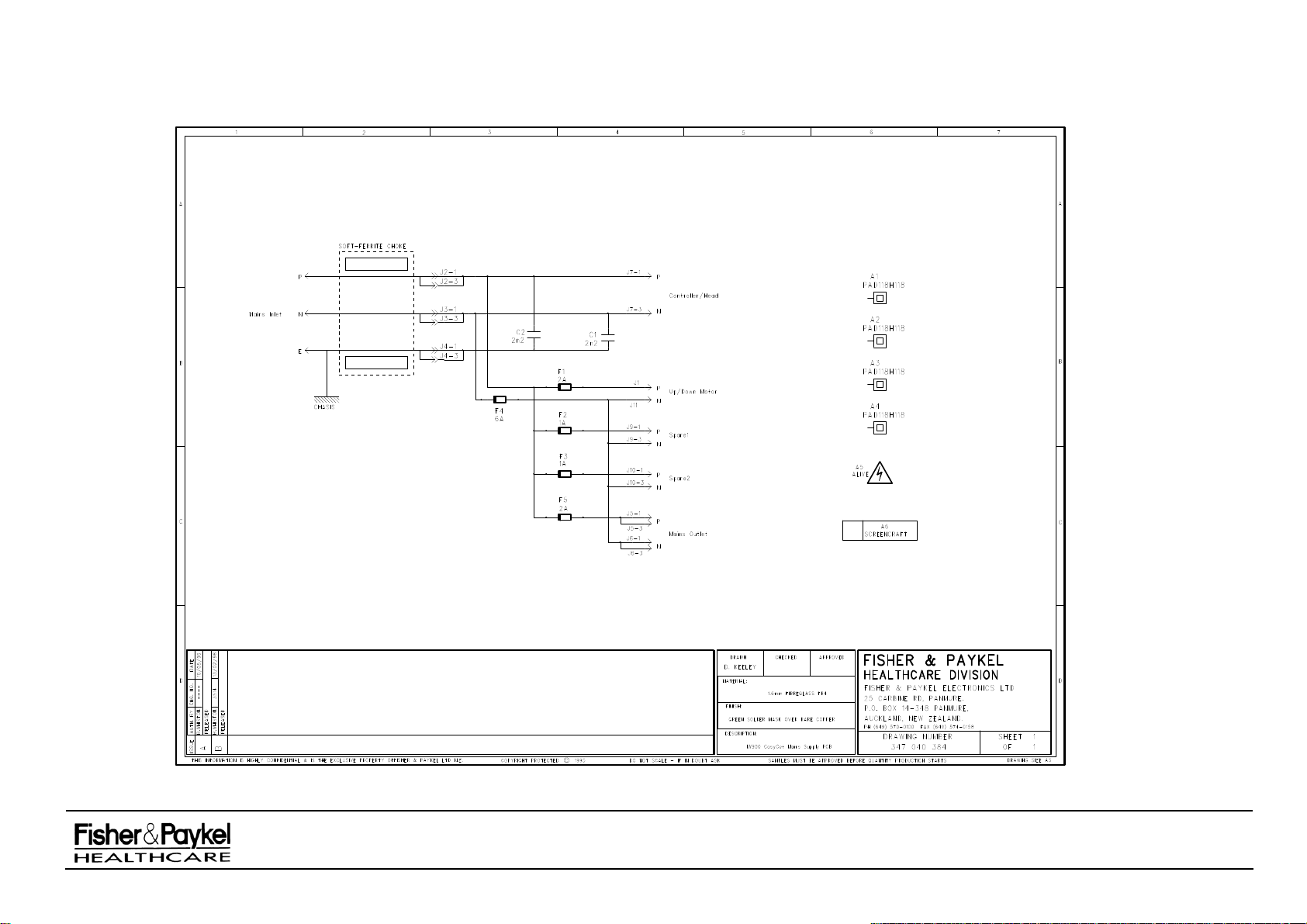
5.5 Circuit Schematics
IW900 Series Service Manual
Manufactured Before June 2008
PART NUMBER :
ISSUE DATE :
ISSUE NUMBER :
PAGE :
185041130
November 2008
I
43
Page 44
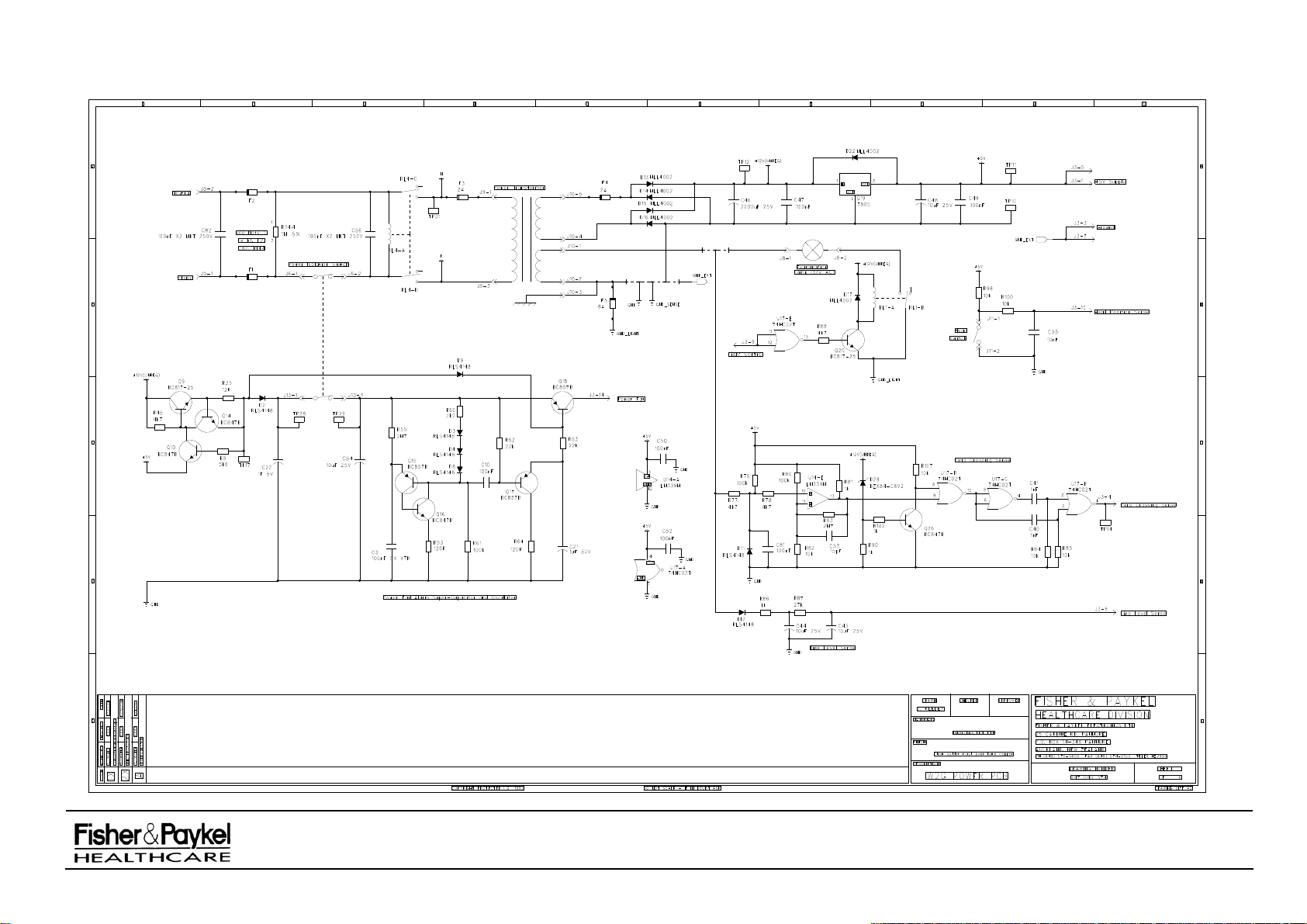
IW900 Series Service Manual
Manufactured Before June 2008
PART NUMBER :
ISSUE DATE :
ISSUE NUMBER :
PAGE :
185041130
November 2008
I
44
Page 45
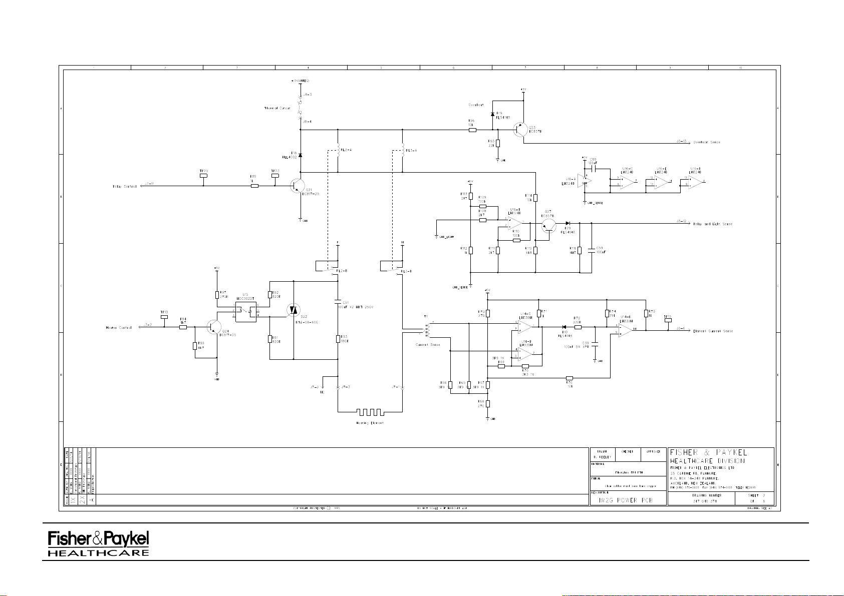
IW900 Series Service Manual
Manufactured Before June 2008
PART NUMBER :
ISSUE DATE :
ISSUE NUMBER :
PAGE :
185041130
November 2008
I
45
Page 46
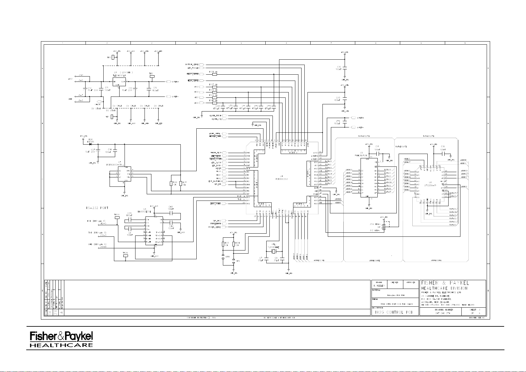
IW900 Series Service Manual
Manufactured Before June 2008
PART NUMBER :
ISSUE DATE :
ISSUE NUMBER :
PAGE :
185041130
November 2008
I
46
Page 47
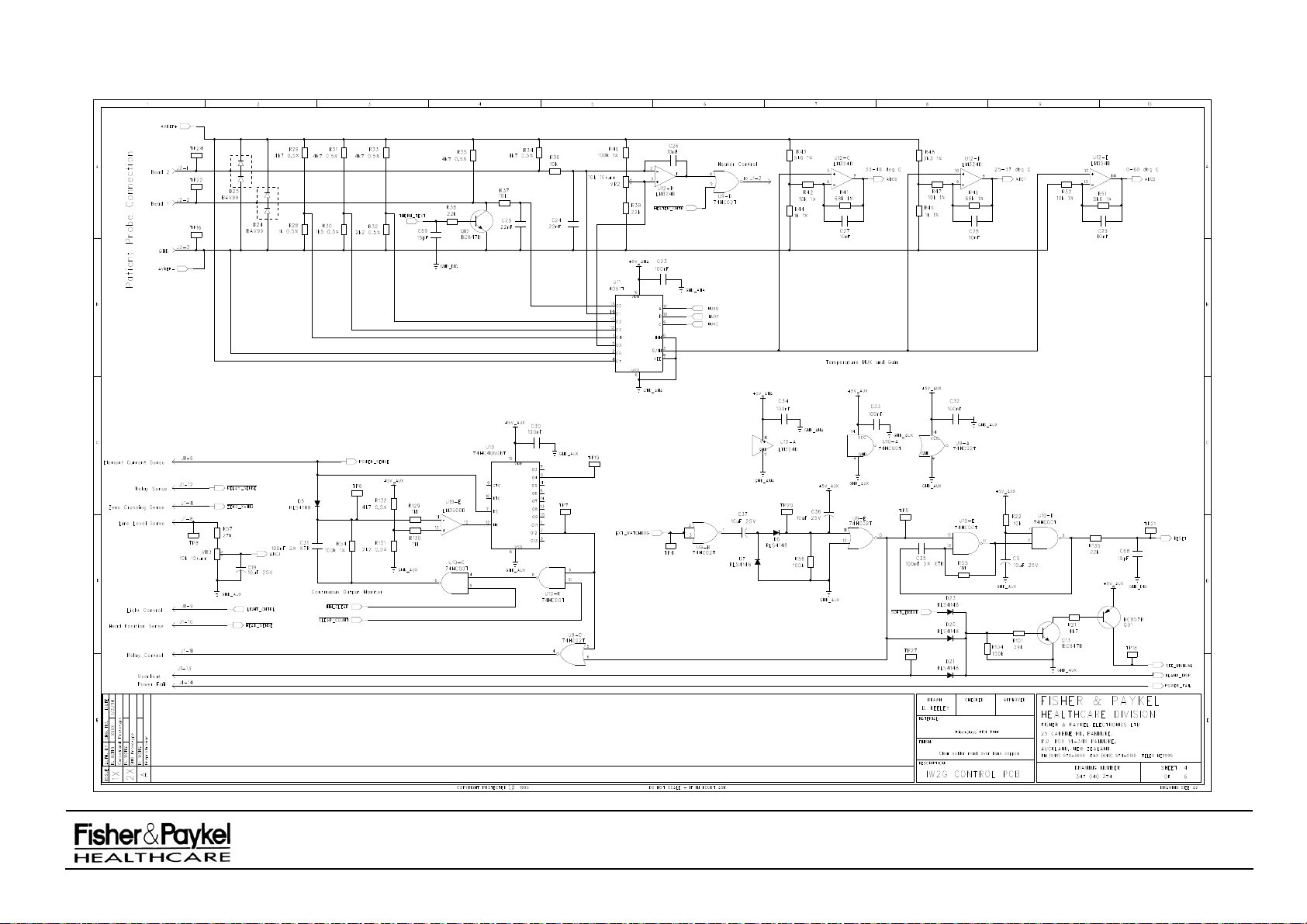
IW900 Series Service Manual
Manufactured Before June 2008
PART NUMBER :
ISSUE DATE :
ISSUE NUMBER :
PAGE :
185041130
November 2008
I
47
Page 48
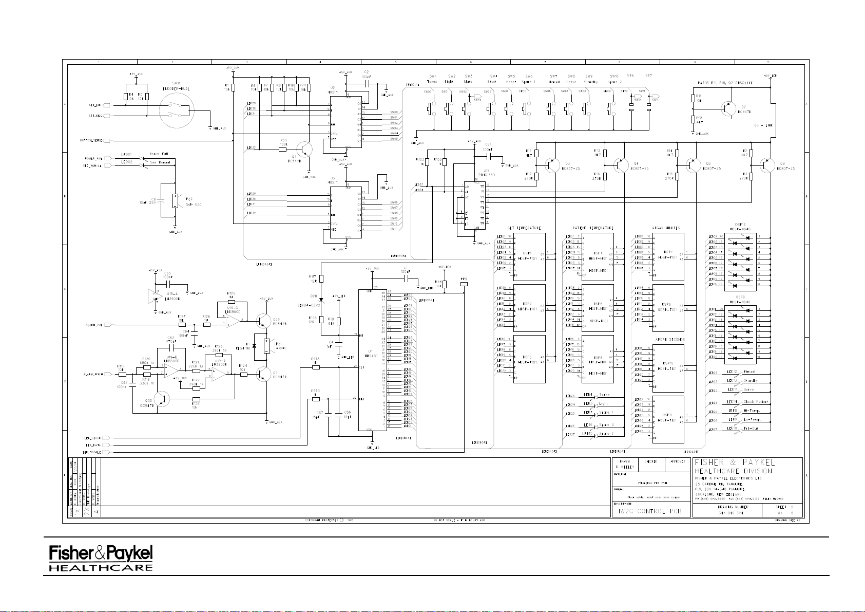
IW900 Series Service Manual
Manufactured Before June 2008
PART NUMBER :
ISSUE DATE :
ISSUE NUMBER :
PAGE :
185041130
November 2008
I
48
Page 49
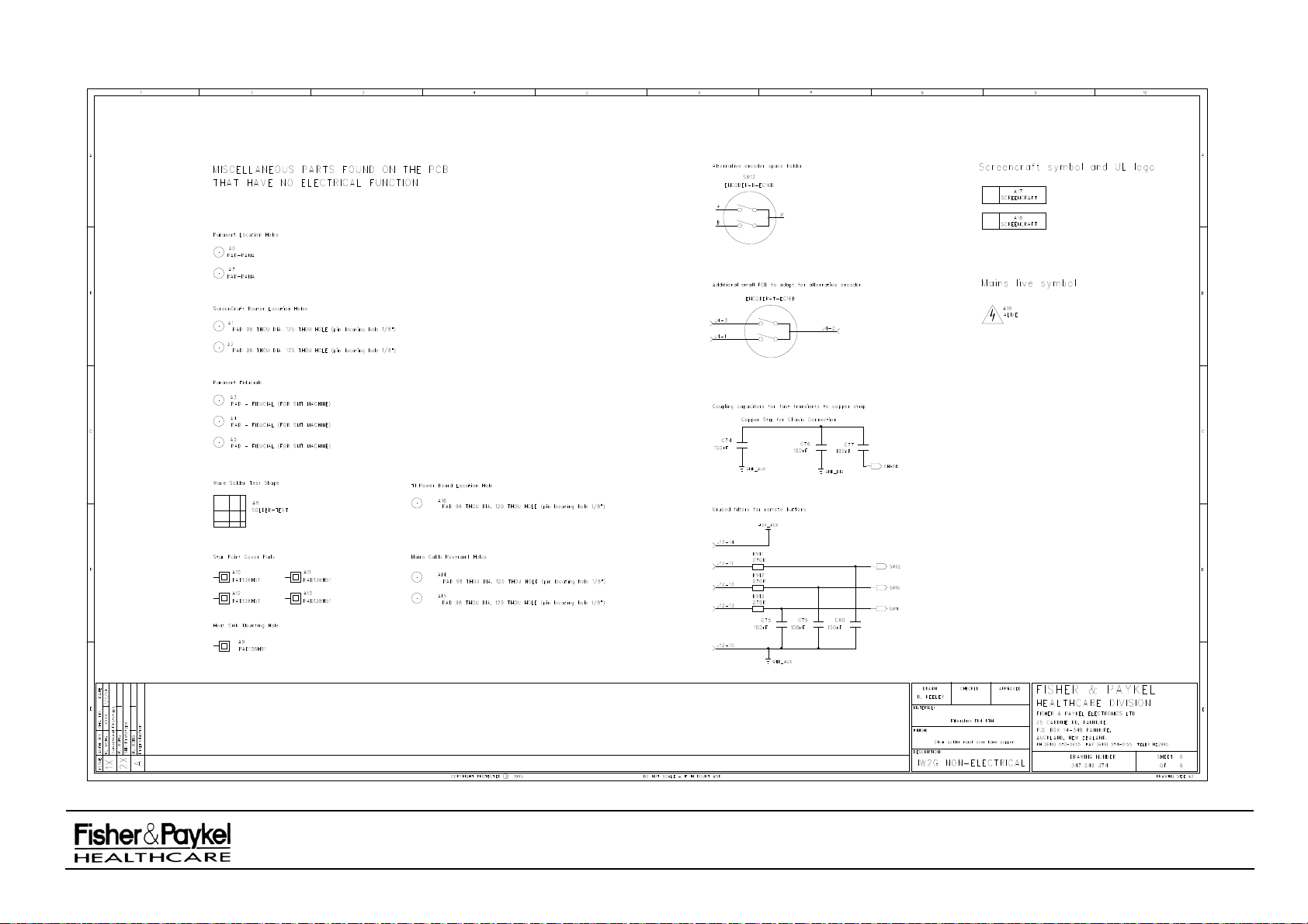
IW900 Series Service Manual
Manufactured Before June 2008
PART NUMBER :
ISSUE DATE :
ISSUE NUMBER :
PAGE :
185041130
November 2008
I
49
Page 50
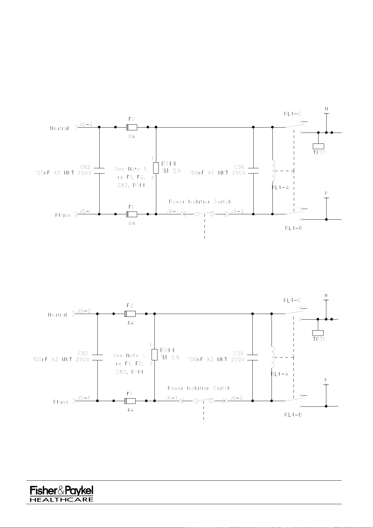
5.5 Circuit Schematics, continued.
The following diagrams are an enlargement of the top left section of the Circuit Diagram on page 44 and
show the fuse ratings for the different models.
The 100nF X2 Capacitor change was effective from early 1997
The 1M resistor change was effective from Serial Number 9892AEA00199. See PART 12: for warmer
serial number identification.
120V Model
230V Model
IW900 Series Service Manual
Manufactured Before June 2008
PART NUMBER :
ISSUE DATE :
ISSUE NUMBER :
PAGE :
185041130
November 2008
I
50
Page 51

PART 6: Head and Column
6.1 Head Assembly
6.1.1 Head Assembly Change History Version 2
From August 2002 changes were made to the upper and lower cases of the head assembly to facilitate
an additional bracket at the rear of the head. This version of head is most easily recognisable by the
extra screw on the bottom face of the head in-between the former hinge.
NOTE: The lower case no longer swings down on a hinge.
A new spares kit was created to allow the replacement of old style upper and lower cases (043042359
– Kit Head Case Replacement) which includes both the upper and lower cases, labels, diffuser glass,
new bracket and Nomex insulation.
Version 1
The original head assembly manufactured from January 1997.
Light Box
The original aluminium light box
(648040141) was replaced with a black injection molded part
(693041858) from October 1998. The two M3 x 16 Taptite screws (614040818) previously used for
retaining the lamp receptacle are not required with the molded part which has snap fits for holding the
receptacle.
In May 2001 the snap fits were altered to fit a new receptacle style. If a replacement light box
(693041858) is required for a warmer prior to this date then a new lamp receptacle (342042009) will
also need to be ordered.
Lamp Receptacle
A new lamp receptacle (342042009) was used from May 2001.
This receptacle can not be retrofitted to
earlier warmers. The original square receptacle (341040500) will not fit into light boxes in warmers
manufactured after May 2001.
Head Manufacture Date
The date of manufacture of the head can be found underneath the head label (3) on the very top of the
head. This manufacture date applies to the head only and should not be used when referring to the
warmer as a whole unit.
Head Nut Removal Spanner
As of June 2003 a bent wire tool (171042012) is available for the removal of the head nut (648040142)
and replaces the plastic tool (171040032) previously included in each warmer.
Swivel Head
From January 2003 the IW910AFS is available. This contains a swivel head for the French Market.
IW900 Series Service Manual
Manufactured Before June 2008
PART NUMBER :
ISSUE DATE :
ISSUE NUMBER :
PAGE :
185041130
November 2008
I
51
Page 52

6.1.2 Head Assembly Parts List
Item Part
Number Description
1 616050011 Screw #8 x 1” csk Phillip’s S/S (Recommended torque 1.2Nm)
2 693040689 Cap support arm
3 183041826 Label head
4 693040666* Case upper head molded
5 183041827 Label warning case internal
6 614040153 Screw #8 x 1" panpozi
7 331040167 Baffle insulation upper case
8 095428265 Harness upper head
9 693041424 Support arm
10 334060011 Sleeving heat shrink 1/4" Viton
11 342042009 Receptacle lamp halogen
12 614040818 Screw M3x16 Taptite (pre September 1998)
13 648040135 Reflector
14 349040128 Thermostat
15 622040508 Washer M5 5.3x12.5 O/D
16 614040153 Screw #8 x 1" panpozi
17 331040164 Insulator element reflector
18 693041858 Light box
19 648040145 Element 100V 450W
648040144 Element 120V 450W
648040134 Element 230V 450W
20 424040069 Halogen lamp 20W
21 195900044 Silicon tape 363 single sided 1"
22 693040665* Case lower head molded
23 433040012 Diffuser glass light
24 614042011 Screw M4 x 10 SS CSK Philips
25 648040140 Grille
26 642042045** Clip Wire Warmer Head
27 642042046** Clip Retainer Warmer Head
28 614042010** Screw M4 x 8 Pan Philips S/S
29 642042050 Bracket Head Rear IW2G
30 614040132 Screw 3x8plas W/Hd Plps2yelchr
31 697042005 Lock Nut Swivel Head Patient Warmer
32 622040150 Washer Arm
33 697042006 Swivel Head Stationary Patient Warmer
34 622040151 Washer Pivot
35 697042007 Swivel Head Rotate Patient Warmer
36 614040864 Screw M5x30 Allen Cap SS
NOTE: Complete heater assembly available as Part No. 043041129 - 230V
043041130 - 120V
043041131 - 100V
* These parts available as a kit of plastic moldings – 043042359 Kit Head Replacement
** These parts only available as a complete kit – 043042239 Kit Warmer Head Clip
NOTE: If the reflector (13) is replaced it is important to ensure that it is correctly aligned inside the upper
case (4). The flats along each side of the reflector have steps cut out from either end to assist
assembly. The reflector is placed in the plastic head molding such that aluminium flat is positioned
under each of the four (two per side) plastic tabs in the upper case. The reflector should sit evenly
in the head under the four front plastic tabs and Nomex.
NOTE: Reflectors manufactured prior to June 2003 were not symmetrical, In this case the end with the
two step cut out goes to the back of the head.
NOTE: The IW910AFS contains extra parts shown inside the box on the next page & that part #16 is
replaced by #36 for this model.
IW900 Series Service Manual
Manufactured Before June 2008
PART NUMBER :
ISSUE DATE :
ISSUE NUMBER :
PAGE :
185041130
November 2008
I
52
Page 53
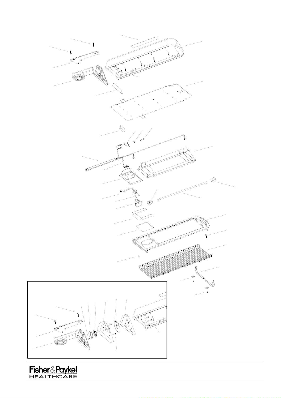
6.1.3 Head Assembly Diagram
1
4
1
2
3
6
7
9
5
16
15
14
29
13
8
IW910AFS ONLY
1
1
30
31
18
11
32
10
21
33
12
20
23
24
34
35
17
27
28
17
19
22
1
25
26
36
2
9
6
IW900 Series Service Manual
Manufactured Before June 2008
PART NUMBER :
ISSUE DATE :
ISSUE NUMBER :
PAGE :
185041130
November 2008
I
53
Page 54

6.2 IW900 Controller Assembly
6.2.1 IW900 Controller Assembly Parts List
Item Part Number Description
1 648040142 Pivot securing nut
2 622040150 Washer arm
3 622040151 Washer pivot
4 693040706 Plug set (5 pieces)
5 614040309 Screw M8 x 20 cap low profile
6 693041423 Column cap top
7 095428283 Harness RS232
8 095428266 Harness lower head
9 616050011 Screw #8 x 1” csk Phillip’s S/S (Recommended torque 1.2Nm)
10 641040815 Extrusion column short
11 043040953 Transformer for 100V models
043040925 Transformer for 120V models
043040902 Transformer for 230V models
12 043041005 PCB Power for 100V models
043041004 PCB Power for 120V models
043041003 PCB Power for 230V models
13 614040117 Screw M4 x 8 Taptite
14 043041145 PCB Control for PW810
043041041 PCB Control for IW910, IW93x, IW960, IW980 (Servo Control models)
043041002 PCB Control for IW920, IW95x, IW970 & IW990 (Manual Control models)
15 095428269 Harness probe
16 341040369 Probe socket, nut and washer
17 043042035 Control panel for IW910, IW93x, IW960, IW980 (Servo Control models)
043042036 Control panel for IW920, IW95x, IW970 & IW990 (Manual Control models)
18 233201602 Fascia Panel - Servo Control
233201603 Fascia Panel - Manual Control
NOTE: Fascia Panels listed below have been superseded from July 2004
233201438 Fascia Panel for Servo Control models - English
233201455 Fascia Panel for Manual Control models - English
233201519 Fascia Panel for Servo Control models - Symbols
233201520 Fascia Panel for Manual Control models - Symbols
19 693040736 Cap probe socket
20 693040677 Control knob plastic
21 349040134 Rocker switch DPDT 10A
22 095428270 Harness mains switch
23 …………… Label fuse for 100V/120V models (specify model number)
…………… Label fuse for 230V models (specify model number)
24 693040271 Knob spacer
25 341040543 Clip adhesive ribbon cable
Replacement Fuses for Power PCB
999830009 Fuse 2A 250V fast blow 20x5mm
(F3 and F4 for all models)
348060023 Fuse 8A 250V fast blow 20x5mm
(F5 for all models, F1 and F2 for 100V/120V models)
348060022 Fuse 4A 250V fast blow 20x5mm
(F1 and F2 for 230V models)
NOTE: 20x5mm fast blow fuses are available from standard electrical suppliers. The correct
replacement fuses are listed on the label inside the front panel (see part 23).
IW900 Series Service Manual
Manufactured Before June 2008
PART NUMBER :
ISSUE DATE :
ISSUE NUMBER :
PAGE :
185041130
November 2008
I
54
Page 55
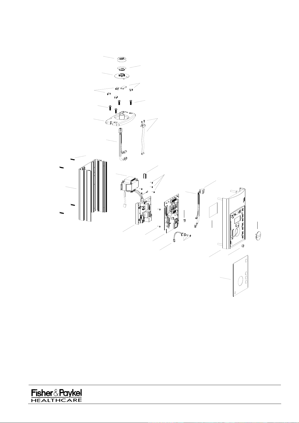
6.2.2 IW900 Controller Assembly Diagram
1
3
4
5
2
4
5
10
6
7
8
9
25
11
13
21
22
24
20
12
13
14
16
23
15
17
19
6.2.3 Power Cords
All power cords have a female IEC plug and the appropriate connection for:
Part Num
ber Country Spare
095428128 Asia Pacific Region and China
095428217 Europe 043042029
095428214 United Kingdom 043042028
095542086 USA and Japan 043042023
095428248 No Plug Fitted
IW900 Series Service Manual
Manufactured Before June 2008
18
PART NUMBER :
ISSUE DATE :
ISSUE NUMBER :
PAGE :
185041130
November 2008
I
55
Page 56

6.3 IW910/920 Mobile Column Assembly
6.3.1 Mobile Column Assembly Parts List
Item Part
Number Description
1 641040763 Bracket support
2 389045063 Ferrite core EMI clamp
3 095428299 Harness mains inlet
4 043042399 Cap plastic column lower - mobile
5 614040309 Screw M8 x 20 cap low profile
6 341050216 Socket power inlet snap mobile
7 647040117 Cable grip p-type
8 614040117 Screw M4x8 Taptite
9 693040706 Plug set (5 pieces)
10 043040978 Pole extendible assembly
11 187040191 Polysleeve 41 mm x 100 cm
12 662040056 Spring mobile warmer pole
13 655040082 Stabiliser weight base mobile
14 651040172 Hook cable
15 693041480 Base mobile finished
16 665040014 Castor locking 50 mm
17 622040624 Washer M12 spring
18 614040614 Screw M12x25 Allen S/S button
IW900 Series Service Manual
Manufactured Before June 2008
PART NUMBER :
ISSUE DATE :
ISSUE NUMBER :
PAGE :
185041130
November 2008
I
56
Page 57
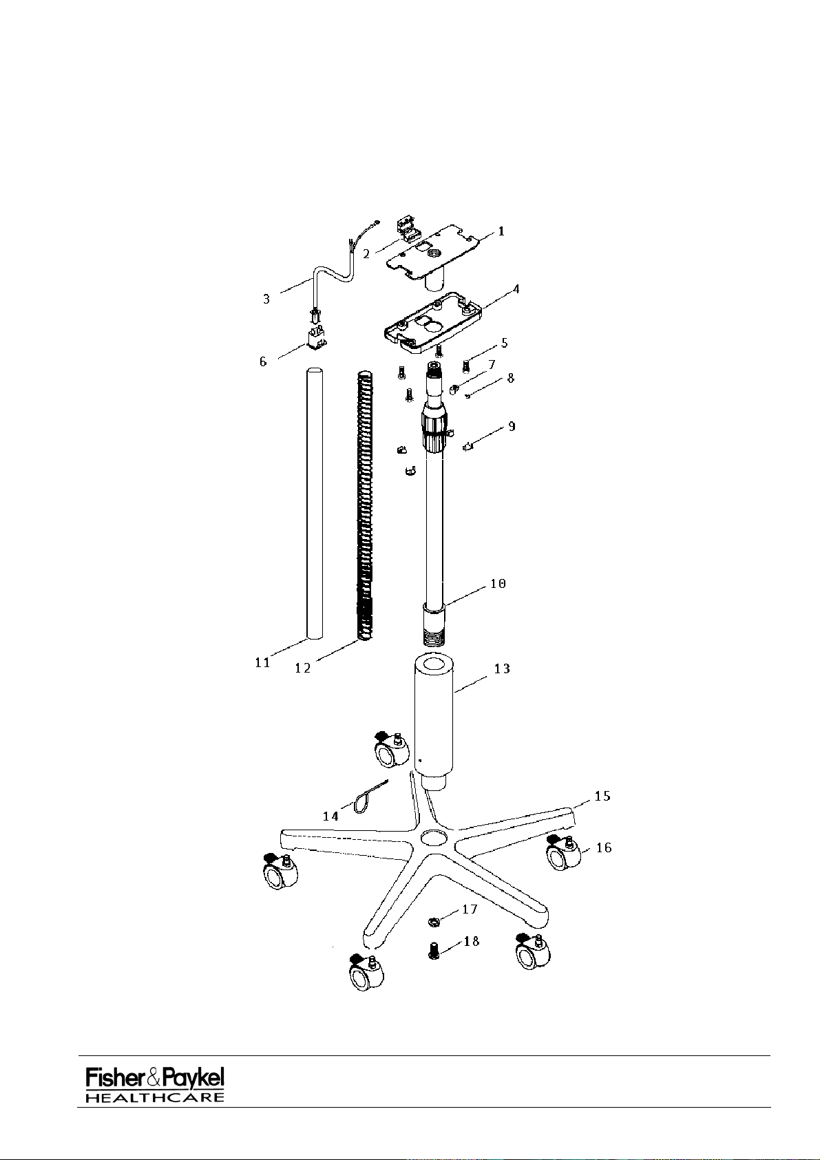
6.3.2 Mobile Column Assembly Diagram
IW900 Series Service Manual
Manufactured Before June 2008
PART NUMBER :
ISSUE DATE :
ISSUE NUMBER :
PAGE :
185041130
November 2008
I
57
Page 58

Intentionally Blank
IW900 Series Service Manual
Manufactured Before June 2008
PART NUMBER :
ISSUE DATE :
ISSUE NUMBER :
PAGE :
185041130
November 2008
I
58
Page 59

6.4 IW93x/95x CosyCot™ Column Assembly
6.4.1 CosyCot Column Assembly
Variations in the column assemblies are most easily discernible by the number of column extrusions
used and are defined as such.
Version 3 – Two Part Column Assembly
From July 2001 the two upper columns were combined into a single column (642042024) and a foam
gasket (331042014) replaced the upper Mylar gasket. The upper column harness (23) was also
changed to remove the middle column earthing points.
Version 2 – Three Part Column Assembly
From July 1998 the single column was replaced with a three-piece construction consisting of a
substantially thicker lower column (641040737) and two standard sections (641040740 and
641040815). Internal Mylar gaskets were added to create an oxygen compartment for the Neopuff
and gas accessories and the dovetail sliders (641040738) increased to 200mm. The column harness
was broken into two harnesses to ensure each section of column was earthed.
Version 1 – Single Column Assembly
The original column assembly manufactured from January 1997 and consisting of a single powder
coated aluminium extrusion as the backbone of the assembly.
Change History
Column – Base Bolt Variations
The original M8 bolts used up until March 1998 were replaced with a separate stud (614040859) that is
fixed into the lower column and a special M8 x 16 screw (614040858). This change is in conjunction
with a change to the base assembly and the studs will only fit into these bases (with 12.8 mm
mounting holes). For earlier bases a replacement bolt (614040346) is available.
IW900 Series Service Manual
Manufactured Before June 2008
PART NUMBER :
ISSUE DATE :
ISSUE NUMBER :
PAGE :
185041130
November 2008
I
59
Page 60

6.4.2 CosyCot Two Part Column Assembly Parts List (Manufactured from July 2001)
Item Part Number Description
1 642042097 Extrusion Column Upper Finished
2 183041960 Label Cover Gas Holes
3 693041492 Cap Column Oxygen II
4 693040746 Cover Label Panel Clear
5 628040048 Pin locator split column
6 614040326 Screw M8 x 16 grub
7 641040738 Extrusion slider dovetail 0.2 m
8 616050011 Screw 8 x 1” CSK Phil (Recommended torque 1.2Nm)
9 614040117 Screw M4 x 8 Pan Phillips
10 647040117 Cable grip - P type
11 641040737 Extrusion column lower
12 614040859 Stud M8 x 40
13 614040132 Screw 3 x 8 plas w/hd
14 341050215 Socket power outlet snap 3 pt
15 341050214 Socket power inlet snap 3 pt
16 233201450 Panel fascia power IW2G
17 693040709 Panels accessories
18 043041137 PCB power supply CosyCot spare
19 095428574 Harness column lower
20 233201451 Panel Fascia Blank IW2G
21 693040735 Gasket foam IW2G
22 336060118 Gasket Column Oxygen Lower
23 095542034 Harness Upper Joined Column
24 331042014 Gasket Column Oxygen Foam
25 183041953 Label Weight vs. Height Warning Symbol
26 642042083 Extrusion Dovetail Frame Mtg
27 661042048 Pin Dowell 20mm SS
28 095428295 Harness supply PCB IW2G
NOTE: For item 1 for Germany the column used is 642042024. Additional holes to accept DIN fittings.
Items 17 and 20 available assembled as Part No. 043041085
IW900 Series Service Manual
Manufactured Before June 2008
PART NUMBER :
ISSUE DATE :
ISSUE NUMBER :
PAGE :
185041130
November 2008
I
60
Page 61
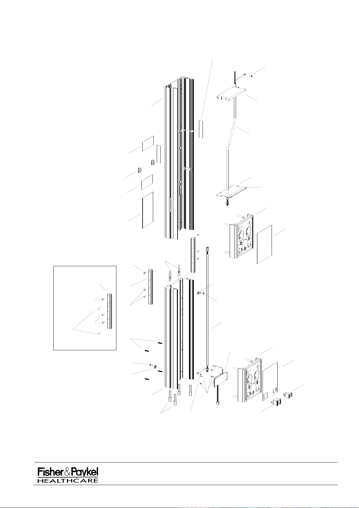
6.4.3 CosyCot Two Part Column Assembly Diagram (Manufactured from July 2001)
25
9
This replaces part 7
from February 2004
3
2
2
4
6
1
24
23
22
21
17
20
5
27
6
6
26
7
6
8
9
10
11
12
9
13
10
9
19
18
17
16
15
14
IW900 Series Service Manual
Manufactured Before June 2008
PART NUMBER :
ISSUE DATE :
ISSUE NUMBER :
PAGE :
185041130
November 2008
I
61
Page 62

6.4.4 CosyCot Three Part Column Assembly Parts List (Manufactured from July 1998 until July 2001)
Item Part Number Description
1 641040815 Extrusion Column Short
2 693040746 Cover Label Panel Clear
3 628040048 Pin locator split column
4 614040309 Screw M8 x 20 cap low profile
5 183041953 Label Weight vs. Height Warning Symbol
6 183041960 Label Cover Gas Holes
7 693041492 Cap Column Oxygen II
8 614040326 Screw M8 x 16 grub
9 641040738 Extrusion slider dovetail 0.2 m
10 641040737 Extrusion column lower
11 616050011 Screw 8 x 1” CSK Phil (Recommended torque 1.2Nm)
12 614040117 Screw M4 x 8 Pan Phillips
13 647040117 Cable grip - P type
14 614040859 Stud M8 x 40
15 614040132 Screw 3 x 8 plas w/hd
16 341050215 Socket power outlet snap 3 pt
17 341050214 Socket power inlet snap 3 pt
18 233201450 Panel fascia power IW2G
19 693040709 Panels accessories
20 043041137 PCB power supply CosyCot spare
21 095428574 Harness column lower
22 693040735 Gasket foam IW2G
23 336060118 Gasket Column Oxygen Lower
24 233201451 Panel Fascia Blank IW2G
25 095428573 Harness Column Upper
26 641040740 Extrusion column middle
27 336060116 Gasket Column Oxygen Upper
NOTE: Items 19 and 24 available assembled as Part No. 043041085
IW900 Series Service Manual
Manufactured Before June 2008
PART NUMBER :
ISSUE DATE :
ISSUE NUMBER :
PAGE :
185041130
November 2008
I
62
Page 63
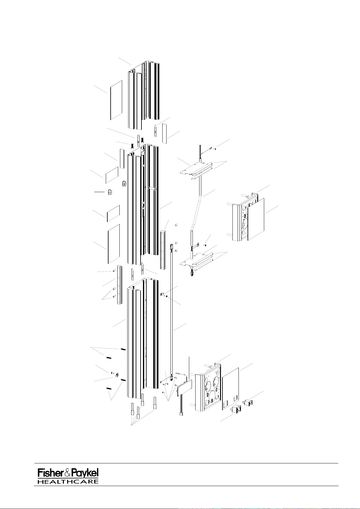
6.4.5 CosyCot Three Part Column Assembly Diagram (Manufactured from July 1998 until July 2001)
1
2
3
6
2
6
7
8
9
8
5
3
4
3
27
9
26
13
5
12
12
25
23
12
22
19
24
22
21
10
11
19
18
12
20
12
13
17
11
15
16
14
IW900 Series Service Manual
Manufactured Before June 2008
PART NUMBER :
ISSUE DATE :
ISSUE NUMBER :
PAGE :
185041130
November 2008
I
63
Page 64

6.4.6 CosyCot Single Column Assembly Parts List (Manufactured from January 1997 until July 1998)
NOTE: For clarity some common components have been omitted. For additional parts information refer
to sections 6.2.2 and 6.4.3.
Item Part
Number Description
1 641040814 Extrusion Column 1430mm
2 693040746 Cover Label Panel Clear
3 183041953 Label Weight vs. Height Warning Symbol
4 641040796 Extrusion slider dovetail 150mm
5 614040326 Screw M8 x 16 grub
6 616050011 Screw 8 x 1” CSK Phil (Recommended torque 1.2Nm)
7 614040117 Screw M4 x 8 Pan Phillips
8 647040117 Cable grip - P type
9 614040132 Screw 3 x 8 plas w/hd
10 043041137 PCB power supply CosyCot spare
11 341050215 Socket power outlet snap 3 pt
12 341050214 Socket power inlet snap 3 pt
13 233201450 Panel fascia power IW2G
14 693040709 Panels accessories
15 614040117 Screw M4 x 8 Pan Phillips
16 095428296 Harness Supply to Power PCB
IW900 Series Service Manual
Manufactured Before June 2008
PART NUMBER :
ISSUE DATE :
ISSUE NUMBER :
PAGE :
185041130
November 2008
I
64
Page 65
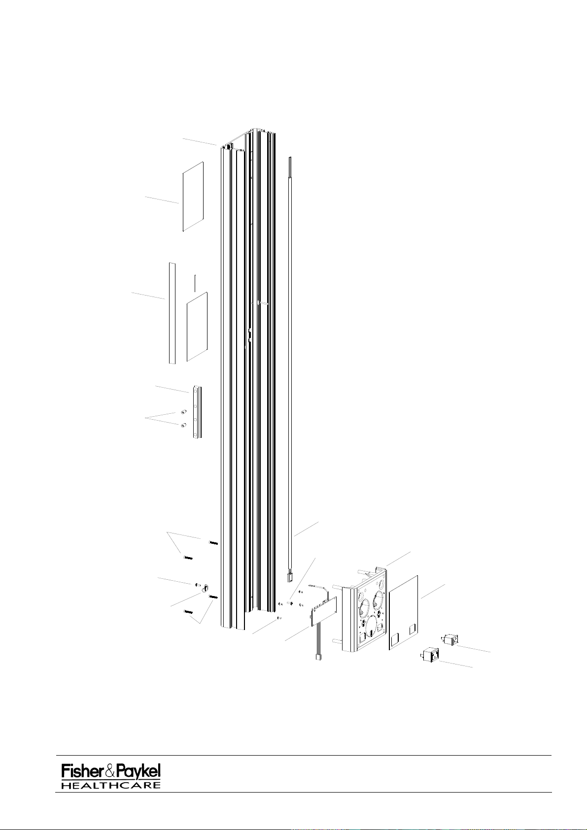
6.4.7 CosyCot Single Column Assembly Diagram (Manufactured from January 1997 until July 1998)
1
2
2
3
5
4
7
6
8
6
9
10
16
15
14
13
12
11
IW900 Series Service Manual
Manufactured Before June 2008
PART NUMBER :
ISSUE DATE :
ISSUE NUMBER :
PAGE :
185041130
November 2008
I
65
Page 66

6.5 IW960/970 Wallmount CosyCot™ Column Assembly
(Discontinued from February 2004)
6.5.1 CosyCot Column Assembly
Change History
The IW960/970 Wallmount CosyCot’shave undergone the same change history in the column
extrusions as for the IW93x/95x CosyCot columns (refer section 6.4.1)
6.5.2 IW960/970 Wall Mount CosyCot Column Parts List
NOTE: The below parts list only specifies those components unique to the IW960/970 Wall
CosyCot’s. For additional parts information refer to section 6.2.2and 5.4.3.
Item Part
Number Description
1 641040827 Bracket wall mount top
2 614040325 Screw M8 x 16 Allen button head
3 641040824 Bracket wall mount bottom
4 614040326 Screw M8 x 16 grub
5 693040741 Cap end column
6 614040309 Screw M8 x 20 cap low profile
7 693040706 Plug set (contains complete set of five plugs)
8 655040088 Block support 50 mm
NOTE: Items 2, 4 & 8 available assembled as Part No. 043041084 – Mounting Block Kit 8mm
Mount
IW900 Series Service Manual
Manufactured Before June 2008
PART NUMBER :
ISSUE DATE :
ISSUE NUMBER :
PAGE :
185041130
November 2008
I
66
Page 67
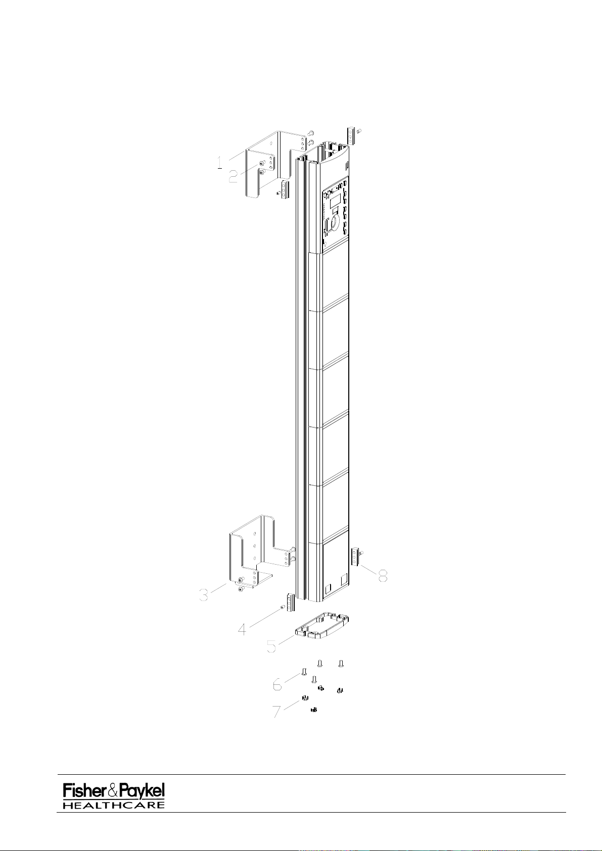
6.5.3 IW960/970 Wall Mount CosyCot Column Assembly Diagram
(Discontinued from February 2004)
IW900 Series Service Manual
Manufactured Before June 2008
PART NUMBER :
ISSUE DATE :
ISSUE NUMBER :
PAGE :
185041130
November 2008
I
67
Page 68

6.6 IW980/990 Wall Mount Column Assembly
6.6.1 IW980/990 Wallmount Column Assembly Parts List
NOTE: The below parts list only specifies those components unique to the IW980/990 Wall
CosyCot’s. For additional parts information refer to section 6.2.2.
Item Part
Number Description
1 693041448 Plug End Wallmount 30mm Square
2 641040821 Bracket Wallmount Aluminium
3 647040117 Cable Grip – P Type
4 693041443 Spacer Bracket to Column IW980/990
5 614040117 Screw M4 x 8 Pan Phillips
6 693040491 Bracket Mounting 30mm x 5mm Tongue
7 641040717 Bracket 30mm C-Slot
8 614040092 Screw M5 x 8 CSK Black Allen
9 614040208 Screw M6 x 25 CSK Allen
10 389045063 Ferrite Core EMI Clamp
11 195680013 Tape Foam Double Sided
12 641040822 Bracket Support Wallmount Steel
13 043042398 Cap Plastic Column Lower - Wall
14 341050216 Socket Power Inlet
15 614040309 Screw M8 x 20 cap low profile
16 693040706 Plug set (contains complete set of five plugs)
17 095428299 Harness Mains Inlet Mobile IW2G
Mount
IW900 Series Service Manual
Manufactured Before June 2008
PART NUMBER :
ISSUE DATE :
ISSUE NUMBER :
PAGE :
185041130
November 2008
I
68
Page 69
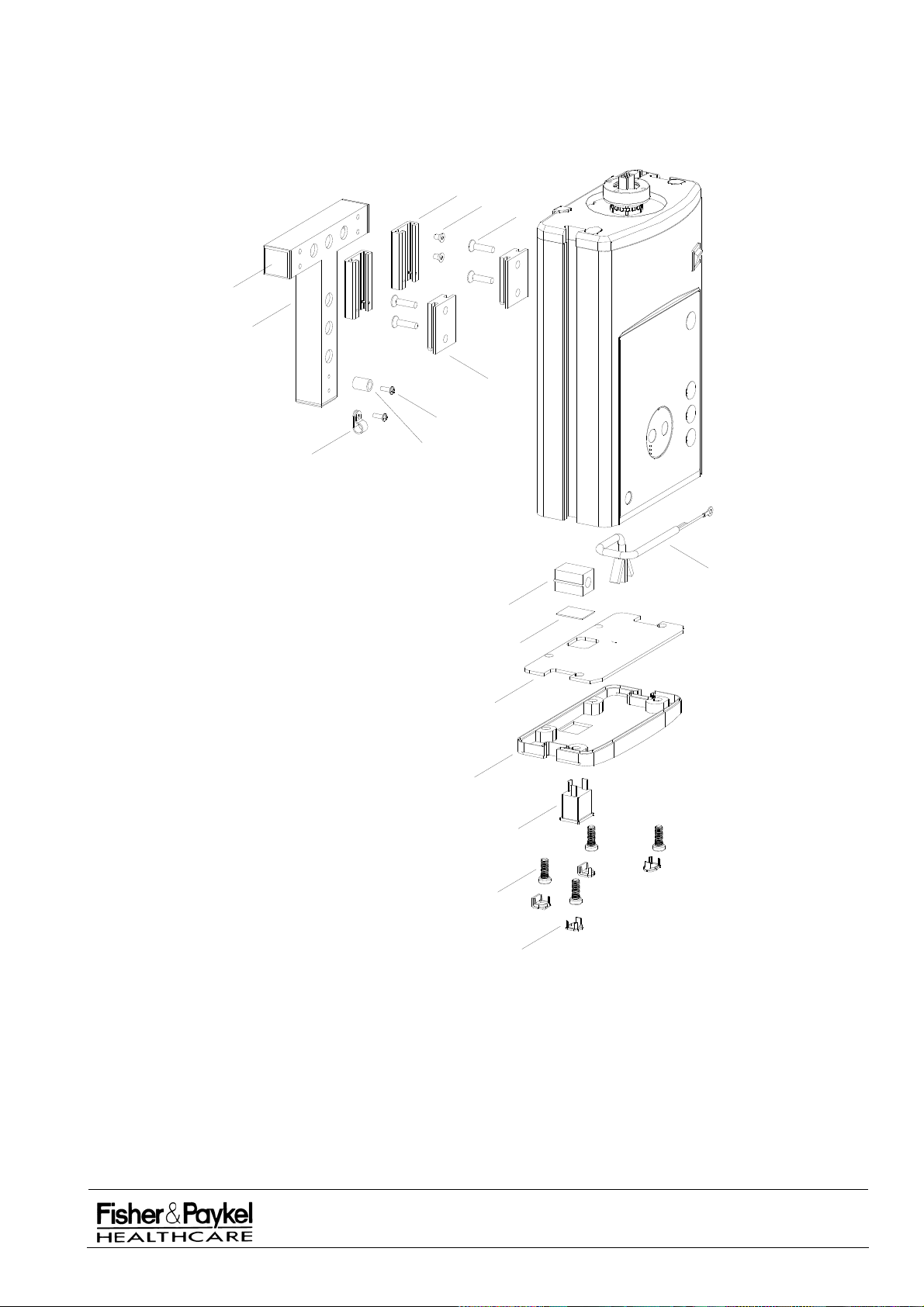
6.6.2 IW980/990 Wall Mount Column Assembly Diagram
7
8
1
2
6
5
9
3
4
17
10
11
12
13
14
15
16
IW900 Series Service Manual
Manufactured Before June 2008
PART NUMBER :
ISSUE DATE :
ISSUE NUMBER :
PAGE :
185041130
November 2008
I
69
Page 70

PART 7: CosyCot™ Bassinet
7.1 Bassinet Change History
Version 3.1
This bassinet is centrally mounted off shoulder bolts rather than brackets off the rear. As a result the
extrusion has extra holes and the brake system has been upgraded.
Version 3
This bassinet has lift and fold side panels and an adjustable transport handle. Also included are silicon
tube tidies in the corner caps and on each of the front and rear panels. A modified bassinet extrusion
removes many of the aluminium dovetail blocks for fixing the rear handle, brake cable and x-ray tray.
Version 2.5
This bassinet has lift and fold side panels and an adjustable transport handle. Also included are silicon
tube tidies in the corner caps and on each of the front and rear panels.
Version 2.1
Version 2.1 varies from its predecessor by the inclusion of high profile corner caps and silicon corner
tube tidies. This change necessitated a new set of side panels (043042201/202).
Version 2.0
In version 2.0 the fabric underlay was replaced by an ABS plastic sheet (255040074) and the corner
block caps replaced with an injection molded part. This model also allowed the use of side panels with
sealing strips to ease cleaning and coincided with the introduction of the long bassinet (900IW212).
Version 1
The original standard bassinet is most easily distinguished by the blue fabric underlay (254040068) on
which the mattress was supported.
IW900 Series Service Manual
Manufactured Before June 2008
PART NUMBER :
ISSUE DATE :
ISSUE NUMBER :
PAGE :
185041130
November 2008
I
70
Page 71
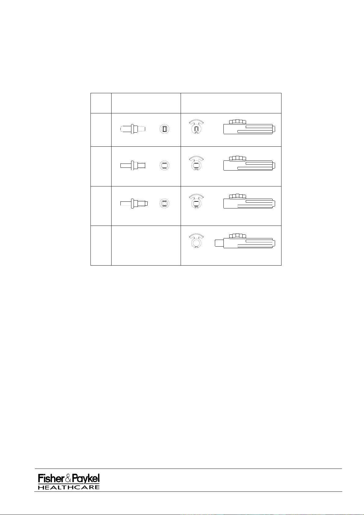
7.2 Side Panel Change History
The full range of side panels are shown in section 7.9. Included in this section is an identification chart
which can be faxed out to customers to ensure accurate identification of the spare side panels when
they are requested. In all instances the second number in each heading refers to a long side panel.
7.2.1 Side Panel Axle Changes
Bassinets prior to version 2.5
contained two dummy axles (693041414) in each corner cap that
interlocked with two sliding axles (693041415) in each side panel.
DUMMY AXLE
- 693041414
SLIDING AXLE - 693041415
A
B
C
D
694042168/9
Type A and Type B
The interlocking rectangular section used on dummy axle (Type A above) was thickened and rounded
on two sides in June 1997 (Type 2). At the same time the corresponding hole in the sliding axle was
enlarged to accommodate the increased axle section.
Type C
In February 2001 an additional circular spigot was added (Type C) to aid in the alignment of the two
axles when installing a side panel. Again the corresponding hole in the sliding axle was lengthened to
accommodate the increased axle length.
Type D
The move to Lift and Fold Side panels in May 2002 resulted in two new sliding axles with a large
protrusion from each (instead of the holes in Types A - C), and the omission of dummy axles all
together.
Upgrading Side Panel Axles
Either Type A or Type B axles can be upgraded to Type C by simply removing the corner cap from the
bassinet, pulling out each axle and inserting new 693041414 axles.
NOTE: The sliding axles in each side panel will also need to be changed.
All hands free side panels from February 2001 onwards used Type C sliding axles and will fit onto both
Type B and Type C dummy axles. Manufacture of the hands free side panels ceased in November
2002 after which dummy axles were no longer required in the assembly.
Side panels manufactured previous to February 2001 will have Type B sliding axles that will NOT fit on
Type C dummy axles. Follow the steps in section 3.5.11 to replace sliding axles if required
IW900 Series Service Manual
Manufactured Before June 2008
PART NUMBER :
ISSUE DATE :
ISSUE NUMBER :
PAGE :
185041130
November 2008
I
71
Page 72

7.3 Bassinet (3.1) Assembly (IW93x, IW95x, IW960 & IW970)
These bassinets have lift and fold side panels and an adjustable transport handle.
Version 3.1 was manufactured from February 2004.
Spare Part Numbers:
043042629 BASSINET V3.1 STD SPARE
043042630 BASSINET V3.1 LONG SPARE
7.3.1 Bassinet (3.1) Assembly Parts List (Manufactured from February 2004)
Item Part
Number Description
1 043042191 Bassinet (3) Side Blank Spare – refer section 7.9.3
2
3
(043042192* Bassinet (3) Side Long Spare – refer section 7.9.3)*
(043042388* Bassinet (3) Side Panel Spare Long with inserts – refer section 7.9.4)*
043042193 Bassinet (3) Side w/ Inserts Spare – refer section 7.9.2
642042043 Block Corner Bassinet
4 642042084 Extrusion Bassinet (3) Painted
(642042023* Extrusion Bassinet (3) Long Painted)*
5 694042167 Cap Corner Keyhole Plastic
6 254040071 Underlay mattress bassinet
(254040073* Underlay Mattress Bassinet Long)*
7 900IW201 Mattress Bassinet IW2G
(900IW213* Mattress Long)*
8 043042190 Handle Bassinet Transport Assembly – refer section 7.10
9
641040811 Handle Rear IW2G
10 694042133 Insert Tube Holder Corner Cap
11 661042045 Cable Brake – Std Bassinet
661042046 Cable Brake – Long Bassinet
12 642042077 Block Handle Stop/Brake Tensioner
13 614042333 Screw M6x35 CSK
14 614040258 Screw M6 x 30 SS Cap
15 693041440 Bush Handle Pivot IW2G
16 694042392 Handle Pivot Pin
17 614040334 Bolt M6 x 75mm Allen Cap SS (Recommended torque 1.2Nm)
18 614040309 Screw M8 x 20 Cap Low Profile
19 614042006 Screw M6 x 25 Cap SS
20 621040524 Nut M6 Nyloc ZPS
21 642042032 Insert Tube Holder Bassinet Side
22 193610025 Adhesive Tape 4950VHB 25m roll
(attaches underlay to extrusion bassinet)
* Denotes substitute part number for 900IW212 Bassinet Long.
IW900 Series Service Manual
Manufactured Before June 2008
PART NUMBER :
ISSUE DATE :
ISSUE NUMBER :
PAGE :
185041130
November 2008
I
72
Page 73
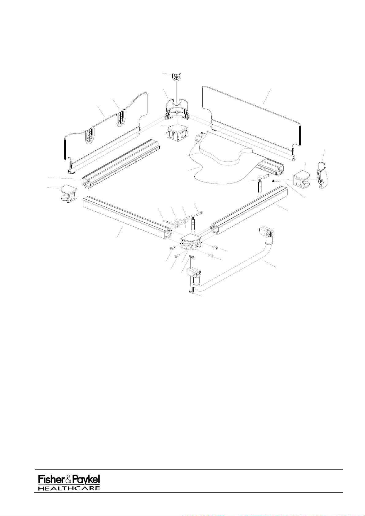
7.3.2 Bassinet (3.1) Assembly Diagram (Manufactured from February 2004)
10
5
1
21
2
3
5
7
3
6
4
16
9
3
11
12
13
14
17
4
15
4
18
18
18
18
3
20
8
19
IW900 Series Service Manual
Manufactured Before June 2008
PART NUMBER :
ISSUE DATE :
ISSUE NUMBER :
PAGE :
November 2008
185041130
I
73
Page 74

7.4 Bassinet (3) Assembly (IW93x, IW95x, IW960 & IW970)
These bassinets have lift and fold side panels and an adjustable transport handle.
Version 3.0 was manufactured from November 2002 to February 2004.
Spare Part Numbers:
043042627 BASSINET V3.0 STD SPARE
043042628 BASSINET V3.0 LONG SPARE
7.4.1 Bassinet (3) Assembly Parts List (Manufactured from November 2002 until February 2004)
Item Part
Number Description
1 043042191 Bassinet (3) Side Blank Spare – refer section 7.9.3
2
3
(043042192* Bassinet (3) Side Long Spare – refer section 7.9.3)*
(043042388* Bassinet (3) Side Panel Spare Long with inserts – refer section 7.9.4)*
043042193 Bassinet (3) Side w/ Inserts Spare – refer section 7.9.2
642042043 Block Corner Bassinet
4 642042022 Extrusion Bassinet (3) Painted
(642042023* Extrusion Bassinet (3) Long Painted)*
5 694042167 Cap Corner Keyhole Plastic
6 254040071 Underlay mattress bassinet
(254040073* Underlay Mattress Bassinet Long)*
7 900IW201 Mattress Bassinet IW2G
(900IW213* Mattress Long)*
8 655040098 Attachment Bassinet Tilt
9 043042190 Handle Bassinet Transport Assembly – refer section 7.10
10
641040811 Handle Rear IW2G
11 694042133 Insert Tube Holder Corner Cap
12 642042019 Cable Tensioner
13 662050070 Cable Brake Bassinet
14 642042034 Block Tilt Limit Handle
15 693041440 Bush Handle Pivot IW2G
16 614040309 Screw M8 x 20 Cap Low Profile
17 614040334 Bolt M6 x 75mm Allen Cap SS (Recommended torque 1.2Nm)
18 614040258 Screw M6 x 30 SS Cap
19 614042006 Screw M6 x 25 Cap SS
20 614040168 Screw M6 x 20 Cap Stainless
21 621040524 Nut M6 Nyloc ZPS
22 100556 Washer M8 x 17 Flat
23 614040326 Screw M8 x 16 Grub Hex Dog Point
24 642042032 Insert Tube Holder Bassinet Side
25 193610025 Adhesive Tape 4950VHB 25m roll
(attaches underlay to extrusion bassinet)
* Denotes substitute part number for 900IW212 Bassinet Long.
IW900 Series Service Manual
Manufactured Before June 2008
PART NUMBER :
ISSUE DATE :
ISSUE NUMBER :
PAGE :
185041130
November 2008
I
74
Page 75
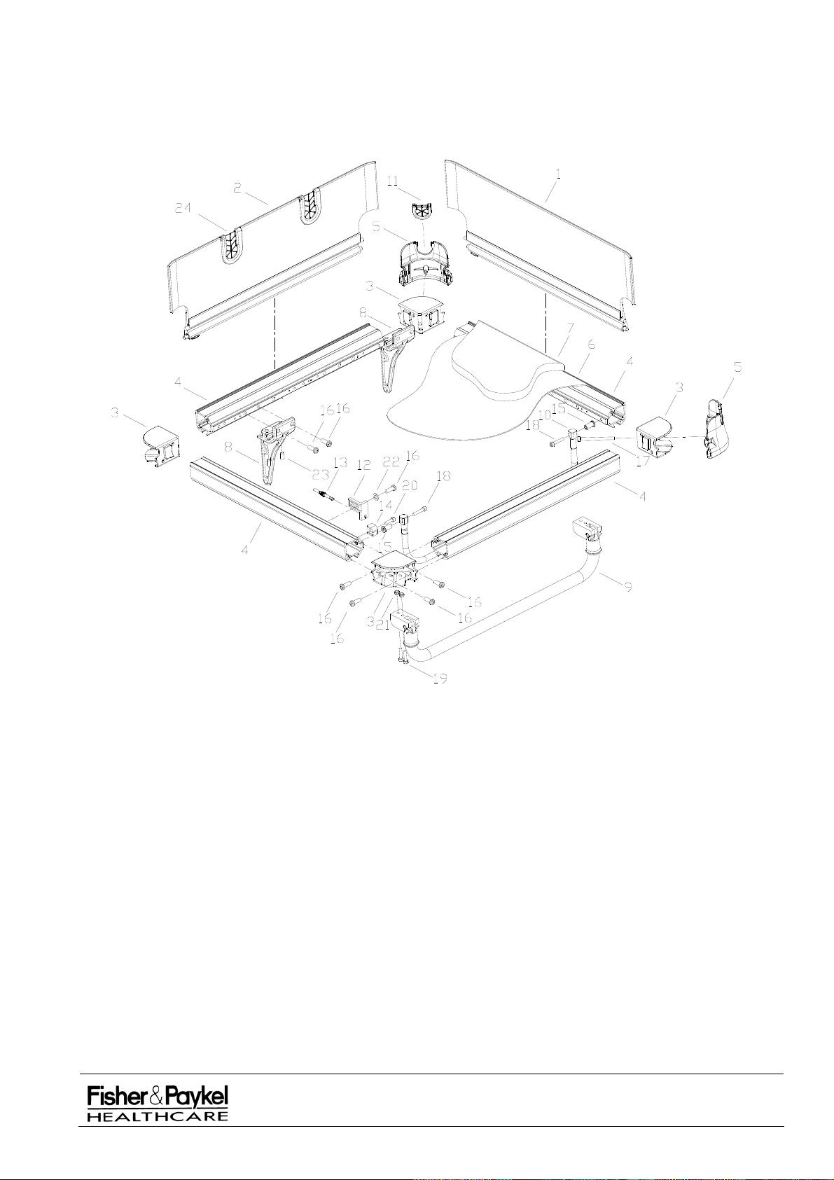
7.4.2 Bassinet (3) Assembly Diagram (Manufactured from August 2002 until February 2004)
IW900 Series Service Manual
Manufactured Before June 2008
PART NUMBER :
ISSUE DATE :
ISSUE NUMBER :
PAGE :
185041130
November 2008
I
75
Page 76

7.5 Bassinet (2.5) Assembly (IW93x, IW95x, IW960 & IW970)
These bassinets have lift and fold side panels and an adjustable transport handle.
Version 2.5 was manufactured from April 2002 to November 2002.
7.5.1 Bassinet (2.5) Assembly Parts List (Manufactured from April 2002)
Item Part
Number Description
1 043042191 Bassinet (3) Side Blank Spare – refer section 7.9.3
2
3
(043042192* Bassinet (3) Side Long Spare – refer section 7.9.3)*
(043042388* Bassinet (3) Side Panel Spare Long with inserts – refer section 7.9.4)*
043042193 Bassinet (3) Side w/ Inserts Spare – refer section 7.9.2
642042043 Block Corner Bassinet
4 641040756 Extrusion Bassinet (2) Painted
(641040834* Extrusion Bassinet (2) Long Painted)*
5 694042167 Cap Corner Keyhole Plastic
6 254040071 Underlay mattress bassinet
(254040073* Underlay Mattress Bassinet Long)*
7 641040796 Slider Dovetail 150mm
8 655040098 Attachment Bassinet Tilt
9 043042190 Handle Bassinet Transport Assembly – refer section 7.10
10
641040811 Handle Rear IW2G
11 694042133 Insert Tube Holder Corner Cap
12 655040096 Block Cable Tensioner IW2G
13 662050070 Cable Brake Bassinet
14 655040095 Block Tilt Limit IW2G
15 693041440 Bush Handle Pivot IW2G
16 614040309 Screw M8 x 20 Cap Low Profile
17 614040334 Bolt M6 x 75mm Allen Cap SS (Recommended torque 1.2Nm)
18 614040258 Screw M6 x 30 SS Cap
19 614042006 Screw M6 x 25 Cap SS
20 614040168 Screw M6 x 20 Cap Stainless
21 621040524 Nut M6 Nyloc ZPS
22 655040093 Block Support Rear Handle
23 614040326 Screw M8 x 16 Grub Hex Dog Point
24 642042032 Insert Tube Holder Bassinet Side
25 694042225 Extrusion Bassinet (2.5) Plastic Standard
(694042226* Extrusion Bassinet (2.5) Plastic Long)
26 900IW201 Mattress Bassinet IW2G
(900IW213* Mattress Long)
27 193610025 Adhesive Tape 4950VHB 25m roll
(attaches underlay to extrusion bassinet)
* Denotes substitute part number for long bassinets.
IW900 Series Service Manual
Manufactured Before June 2008
PART NUMBER :
ISSUE DATE :
ISSUE NUMBER :
PAGE :
185041130
November 2008
I
76
Page 77
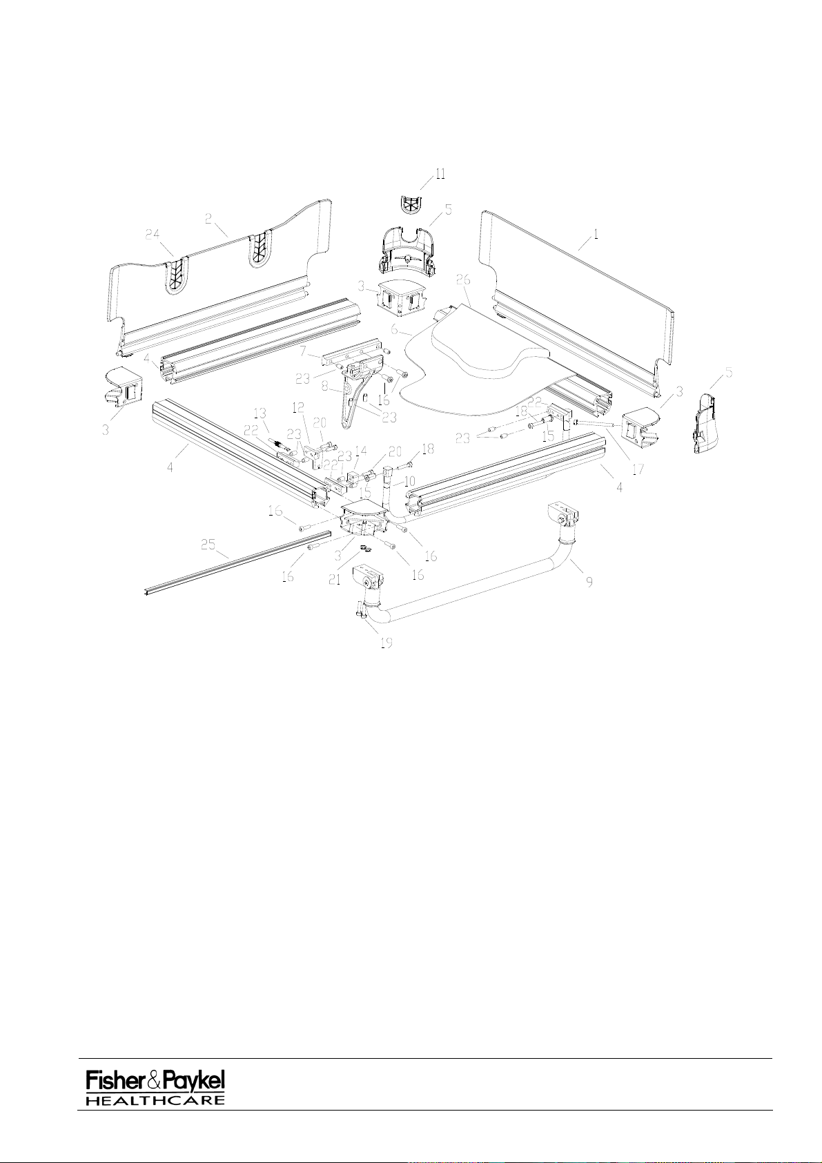
7.5.2 Bassinet (2.5) Assembly Diagram (Manufactured from May 2002 to August 2002)
IW900 Series Service Manual
Manufactured Before June 2008
PART NUMBER :
ISSUE DATE :
ISSUE NUMBER :
PAGE :
185041130
November 2008
I
77
Page 78

7.6 Bassinet (2.1) Assembly (IW93x, IW95x)
Version 2.1 has high profile corner caps with hands free sides. The addition of the corner tube tidies
meant the side panel slots could be removed. Otherwise this model is identical to version 2.0.
Version 2.1 was manufactured from Jan 2002 to April 2002.
7.6.1 Bassinet (2.1) Assembly Parts List
Item Part
Number Description
1 043042201 Bassinet (2) Side with Seal – refer section 7.9.8
(043042202*
2
900IW201 Mattress Bassinet IW2G
Bassinet (2) Side Long with Seal – refer section 7.9.8)*
(900IW213* Mattress Long)*
3 641040817 Block Corner Bassinet Painted
4 641040756 Extrusion Bassinet (2) Painted
(641040834* Extrusion Bassinet (2) Long Painted)*
5 694042134 Cap Corner Keyhole Plastic
6 254040071 Underlay mattress bassinet
(254040073* Underlay Mattress Bassinet Long)*
7 641040796 Slider Dovetail 150mm
8 655040098 Attachment Bassinet Tilt
9 641040810 Handle front
10 641040811 Handle Rear IW2G
11 655040092 Block Support Front Handle
12 655040096 Block Cable Tensioner IW2G
13 662050070 Cable Brake Bassinet
14 655040095 Block Tilt Limit IW2G
15 693041440 Bush Handle Pivot IW2G
16 614040309 Screw M8 x 20 Cap Low Profile
17 614040334 Bolt M6 x 75mm Allen Cap SS (Recommended torque 1.2Nm)
18 614040258 Screw M6 x 30 SS Cap
19 653040121 Bush Corner Cap
20 614040168 Screw M6 x 20 Cap Stainless
21 693041414 Axle Dummy
22 655040093 Block Support Rear Handle
23 614040326 Screw M8 x 16 Grub Hex Dog Point
24 693041413 Clip IW2G Plastic
25 694042133 Insert Tube Holder Corner Cap
26 193318825 Adhesive Tape 4950VHB 25m roll
(attaches underlay to extrusion bassinet)
* Denotes substitute part number for long bassinets.
IW900 Series Service Manual
Manufactured Before June 2008
PART NUMBER :
ISSUE DATE :
ISSUE NUMBER :
PAGE :
185041130
November 2008
I
78
Page 79
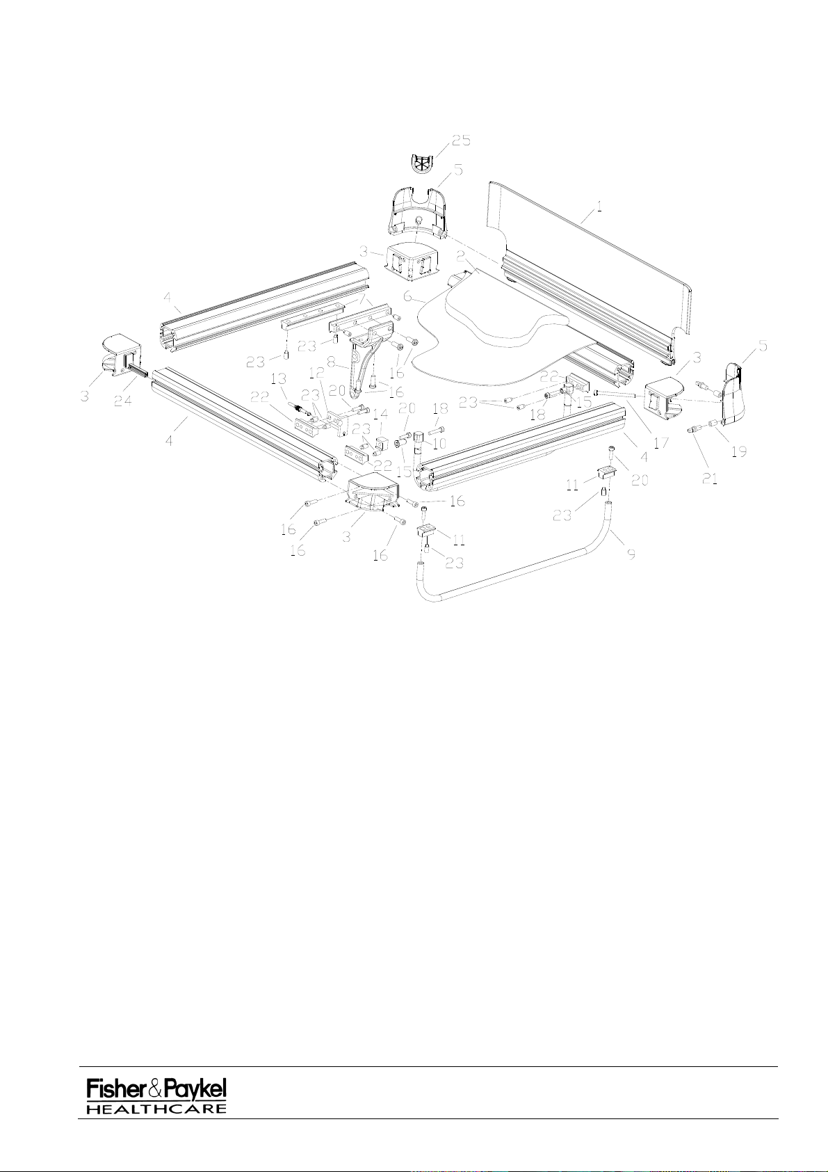
7.6.2 Bassinet (2.1) Assembly Diagram (Manufactured from Jan 2002 to April 2002)
IW900 Series Service Manual
Manufactured Before June 2008
PART NUMBER :
ISSUE DATE :
ISSUE NUMBER :
PAGE :
185041130
November 2008
I
79
Page 80

7.7 Bassinet (2.0) Assembly (IW93x, IW95x, IW960 & IW970)
In version 2.0 the fabric underlay was replaced by an ABS plastic sheet (255040074) and the corner
block caps replaced with an injection molded part (641040819). This model also allowed the use of side
panels with sealing strips to ease cleaning. A long bassinet (900IW212) was also introduced with this
version.
Version 2.0 was manufactured from April 1998 to Jan 2002.
7.7.1 Bassinet (2.0) Assembly Parts List
Item Part
Number Description
1 043042096 Bassinet Side with Seal – refer section 7.9.9
2
043041062 Bassinet Side No Seal – refer section 7.9.10
(043042095* Bassinet Side Long with Seal – refer section 7.9.9)*
(043041332* Bassinet Side Long No Seal – refer section 7.9.10)*
900IW201 Mattress Bassinet IW2G
(900IW213* Mattress Long)*
3 641040817 Block Corner Bassinet Painted
4 641040756 Extrusion Bassinet (2) Painted
(641040834* Extrusion Bassinet (2) Long Painted)*
5 641040819 Cap Corner Block Plastic
6 254040071 Underlay mattress bassinet
(254040073* Underlay Mattress Bassinet Long)*
7 641040796 Slider Dovetail 150mm
8 655040098 Attachment Bassinet Tilt
9 641040810 Handle front
10 641040811 Handle Rear IW2G
11 655040092 Block Support Front Handle
12 655040096 Block Cable Tensioner IW2G
13 662050070 Cable Brake Bassinet
14 655040095 Block Tilt Limit IW2G
15 693041440 Bush Handle Pivot IW2G
16 614040309 Screw M8 x 20 Cap Low Profile
17 614040334 Bolt M6 x 75mm Allen Cap SS (Recommended torque 1.2Nm)
18 614040258 Screw M6 x 30 SS Cap
19 653040121 Bush Corner Cap
20 614040168 Screw M6 x 20 Cap Stainless
21 693041414 Axle Dummy
22 655040093 Block Support Rear Handle
23 614040326 Screw M8 x 16 Grub Hex Dog Point
24 693041413 Clip IW2G Plastic
25 193610025 Adhesive Tape 4950VHB 33m roll
(attaches underlay to extrusion bassinet – not shown)
* Denotes substitute part number for long bassinets.
IW900 Series Service Manual
Manufactured Before June 2008
PART NUMBER :
ISSUE DATE :
ISSUE NUMBER :
PAGE :
185041130
November 2008
I
80
Page 81
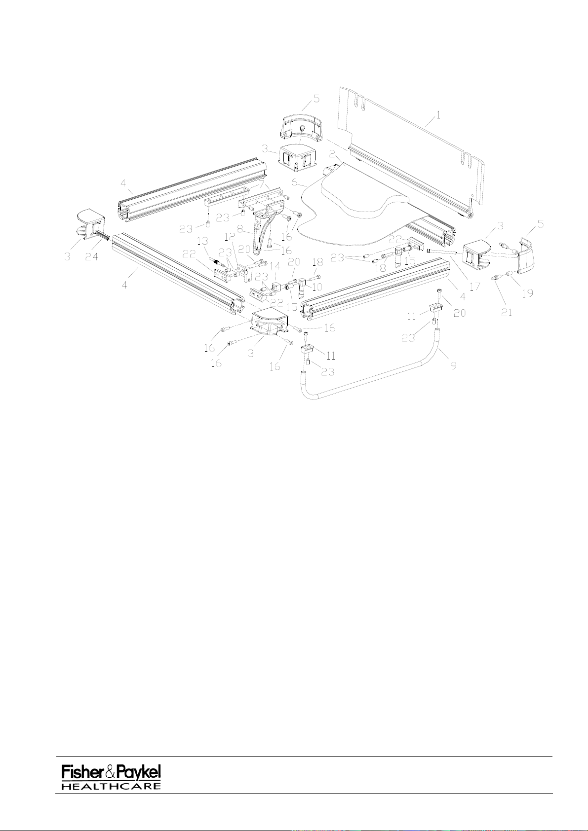
7.7.2 Bassinet (2.0) Assembly Diagram (Manufactured from April 1998 to Jan 2002)
IW900 Series Service Manual
Manufactured Before June 2008
PART NUMBER :
ISSUE DATE :
ISSUE NUMBER :
PAGE :
185041130
November 2008
I
81
Page 82

7.8 Bassinet (1.0) Assembly (IW93x, IW95x, IW960 & IW970)
The original standard bassinet had a fabric underlay (254040068) to support the mattress and stainless
steel corner block caps (now replaced by part 641040819). No long bassinet was available in this
version.
Version 1.0 was manufactured from January 1997 to April 1998.
7.8.1 Bassinet (1.0) Assembly Parts List
Item Part
Number Description
1 043041062 Bassinet Side No Seal – refer section 7.9.10
2
900IW201 Mattress Bassinet IW2G
3 641040817 Block Corner Bassinet Painted
4 641040812 Extrusion Bassinet Finished
5 641040819 Cap Corner Block Plastic
6 254040068* Mattress bottom bassinet IW2G*
7 641040796 Slider Dovetail 150mm
8 655040098 Attachment Bassinet Tilt
9 641040810 Handle front
10 641040811 Handle Rear IW2G
11 655040092 Block Support Front Handle
12 655040096 Block Cable Tensioner IW2G
13 662050070 Cable Brake Bassinet
14 655040095 Block Tilt Limit IW2G
15 693041440 Bush Handle Pivot IW2G
16 614040309 Screw M8 x 20 Cap Low Profile
17 614040334 Bolt M6 x 75mm Allen Cap SS (Recommended torque 1.2Nm)
18 614040258 Screw M6 x 30 SS Cap
19 653040121 Bush Corner Cap
20 614040168 Screw M6 x 20 Cap Stainless
21 693041414 Axle Dummy
22 655040093 Block Support Rear Handle
23 614040326 Screw M8 x 16 Grub Hex Dog Point
24 693041413 Clip IW2G Plastic
* The blue fabric underlay can be replaced with a white 2mm thick ABS plastic underlay by ordering
kit 043042441 – Underlay Upgrade Kit Std bassinet.
IW900 Series Service Manual
Manufactured Before June 2008
PART NUMBER :
ISSUE DATE :
ISSUE NUMBER :
PAGE :
185041130
November 2008
I
82
Page 83
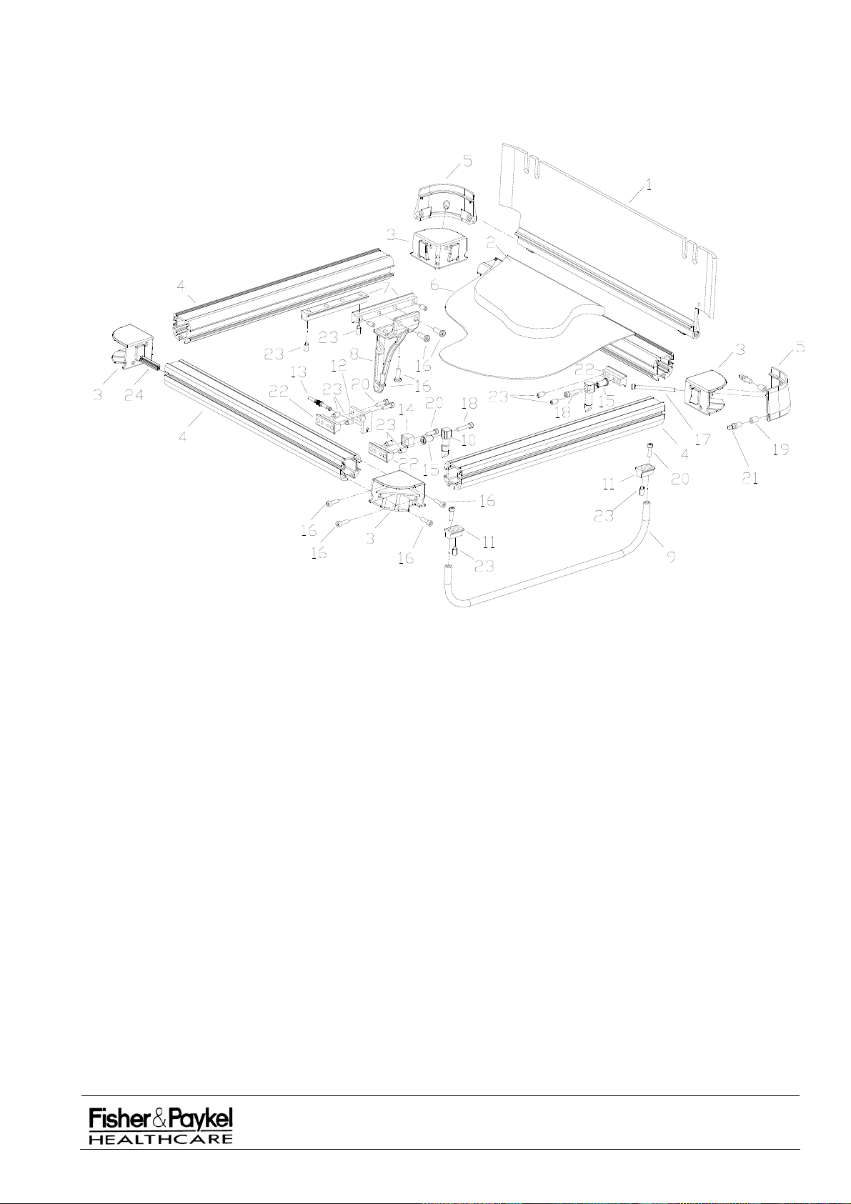
7.8.2 Bassinet (1) Assembly Diagram (Manufactured from January 1997 to April 1998)
IW900 Series Service Manual
Manufactured Before June 2008
PART NUMBER :
ISSUE DATE :
ISSUE NUMBER :
PAGE :
185041130
November 2008
I
83
Page 84
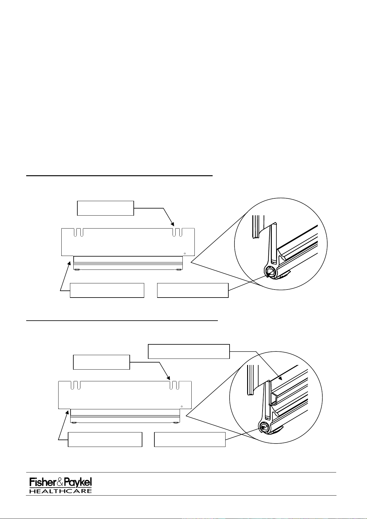
7.9 Bassinet Side Panel Assembly (IW93x, IW95x, IW960 & IW970)
7.9.1 Bassinet Side Panel Identification
The improvements in bassinet design have resulted in a
number of different bassinet side panels. The
diagrams below will enable you to identify the correct side panel. The side panels vary depending on
the following factors:
Length of side panel
Height of side panel
Height of bassinet corner caps – standard or high profile
Sliding Axle style – hole or stub
Tube tidy style – rigid or inserts
Santoprene sealing strip
043041062/043041332* Bassinet Side No Seal (*Long)
These are hands free side panels designed for version 1.0 bassinets which have standard corner caps
(641040819) and a fabric underlay (254040068).
Rigid Tube Tidy
Standard Corner Profile Sliding Axle with hole
043042096/043042095* Bassinet Side with Seal (*Long)
These are hands free side panels designed for version 2.0 bassinets with standard corner caps
(641040819) and a plastic mattress underlay (254040071).
Santoprene Sealing Strip
Rigid Tube Tidy
Standard Corner Profile Sliding Axle with hole
IW900 Series Service Manual
Manufactured Before June 2008
PART NUMBER :
ISSUE DATE :
ISSUE NUMBER :
PAGE :
185041130
November 2008
I
84
Page 85
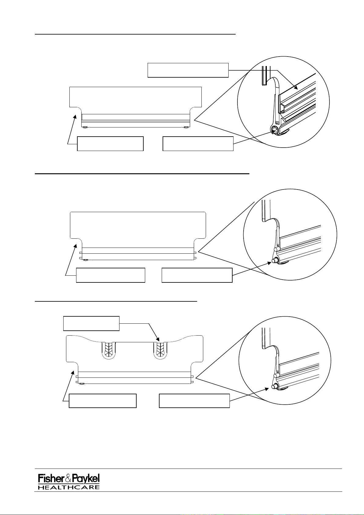
043042201/043042202* Bassinet (2) Side with Seal (*Long)
These are hands free side panels designed for version 2.1 bassinets with high profile corner caps
(694042167) containing CornerGrip Tube holders (694042133) and a plastic underlay (254040071).
Santoprene Sealing Strip
High Corner Profile Sliding Axle with hole
043042191/043042192* Bassinet (3) Blank Side Panels (*Long)
These are lift and fold side panels that will only fit on version 2.5 and 3.0 bassinets.
High Corner Profile Sliding Axle with stub
043042193 Bassinet (3) Side Panel with Inserts
This is a lift and fold side panel that will only fit on version 2.5 and 3.0 bassinets.
Tube Tidy Insert
High Corner Profile Sliding Axle with stub
IW900 Series Service Manual
Manufactured Before June 2008
PART NUMBER :
ISSUE DATE :
ISSUE NUMBER :
PAGE :
185041130
November 2008
I
85
Page 86
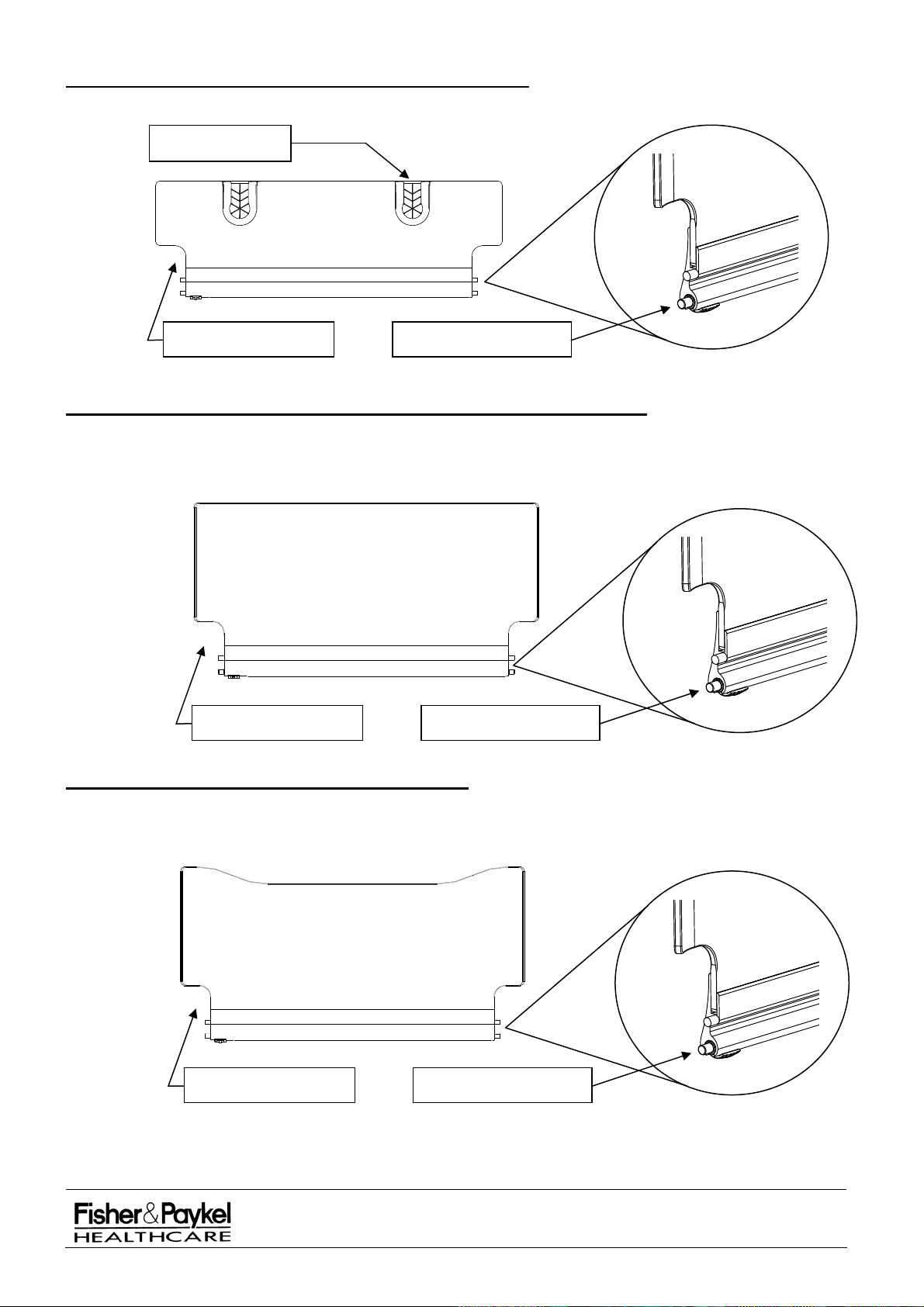
043042388 Bassinet (3) Side Panel Long with Inserts
This is a lift and fold side panel that will only fit on version 2.5 and 3.0 bassinets.
Tube Tidy Insert
High Corner Profile Sliding Axle with stub
043042509/043042561* Bassinet (3) Side Panel High Blank (*Long)
This is a lift and fold side panel that will only fit on version 2.5 and 3.0 bassinets.
High Corner Profile Sliding Axle with stub
043042510 Bassinet (3) Side Panel High Front
This is a lift and fold side panel that will only fit on version 2.5 and 3.0 bassinets.
High Corner Profile Sliding Axle with stub
IW900 Series Service Manual
Manufactured Before June 2008
PART NUMBER :
ISSUE DATE :
ISSUE NUMBER :
PAGE :
185041130
November 2008
I
86
Page 87
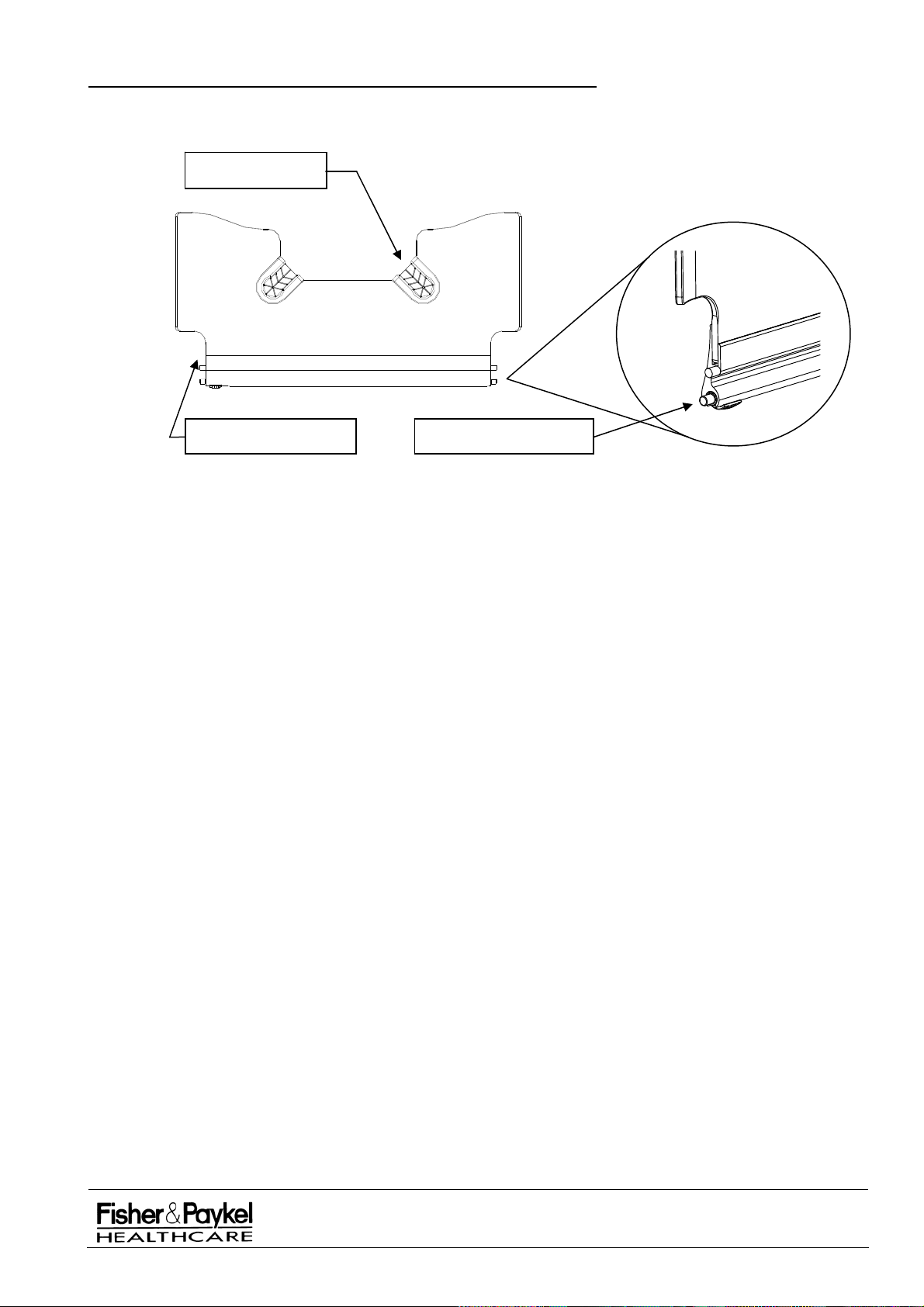
043042511 Bassinet (3) Side Panel High Back with Inserts
This is a lift and fold side panel that will only fit on version 2.5 and 3.0 bassinets.
Tube Tidy Insert
High Corner Profile Sliding Axle with stub
IW900 Series Service Manual
Manufactured Before June 2008
PART NUMBER :
ISSUE DATE :
ISSUE NUMBER :
PAGE :
185041130
November 2008
I
87
Page 88
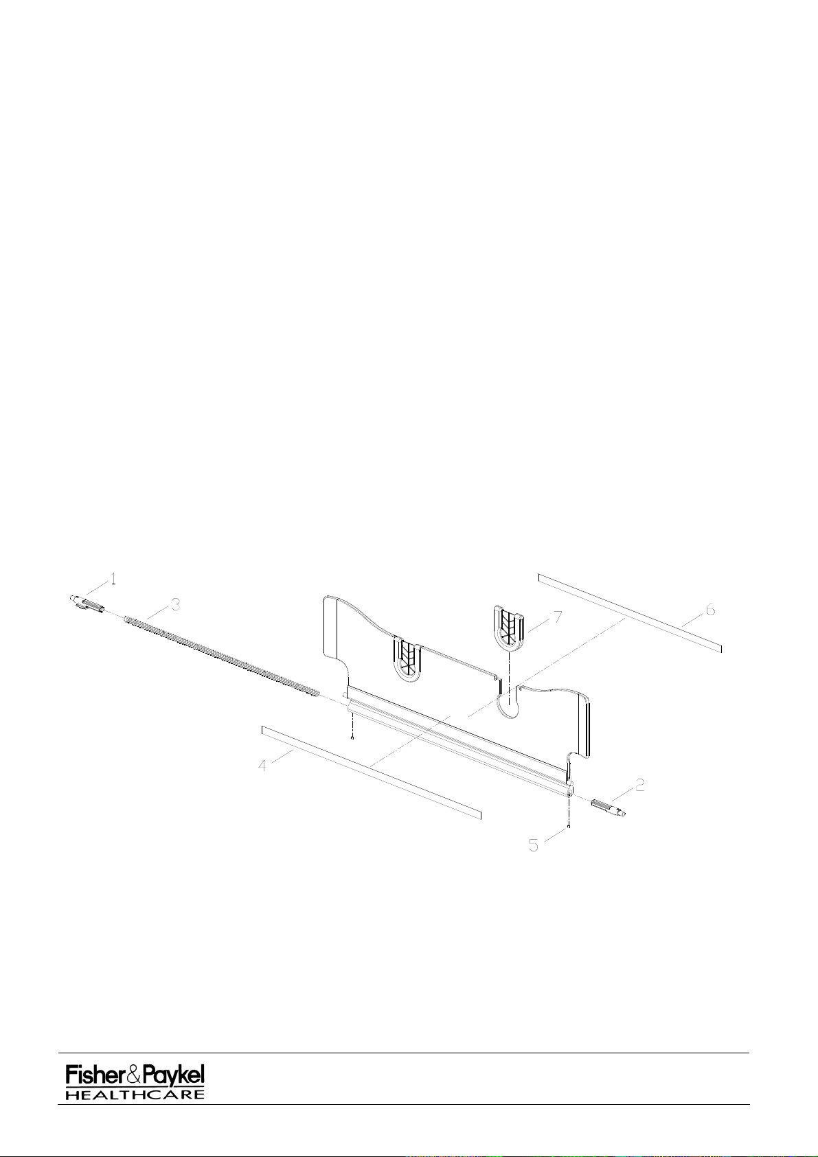
7.9.2 043042193 Bassinet (3) Side Panel with Inserts
Order Number and Description:
043042193 Bassinet (3) Side with inserts Spare
NOTE: This is a lift and fold side panel which will only fit on bassinets version 2.5 and greater.
Bassinet (3) Side Panel with Inserts Parts List
Item Part
Number Description
1 694042168 Axle Sliding (3)
2 694042169 Axle Sliding Machined (3)
3 661042031 Spring Bassinet Side (3)
4 183042046 Label Blank Side Panel (3)
5 614040287 Screw M3 x 4 Grub Knurled
6 183041870 Sticker X-Ray Tray End
7 694042132 Insert Tube Holder - Bassinet side
Bassinet (3) Side Panel with Inserts Assembly Diagram
IW900 Series Service Manual
Manufactured Before June 2008
PART NUMBER :
ISSUE DATE :
ISSUE NUMBER :
PAGE :
185041130
November 2008
I
88
Page 89
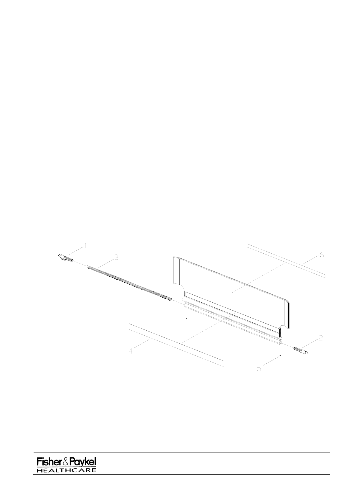
7.9.3 043042191/043042192* Bassinet (3) Blank Side Panel (*Long)
Order Number and Description:
043042191
Bassinet (3) Side Blank Spare
043042192 Bassinet (3) Side Long Spare
NOTE: These are lift and fold side panels that will only fit on bassinets version 2.5 and greater.
Bassinet (3) Blank Side Panel Parts List
Item Part
Number Description
1 694042168 Axle Sliding (3)
2 694042169 Axle Sliding Machined (3)
3 661042031 Spring Bassinet Side (3)
(661042032* Spring Bassinet Side (3) Long)*
4 183042046 Label Blank Side Panel (3)
(183042047* Label Blank Side Panel (3) Long)*
5 614040287 Screw M3 x 4 Grub Knurled
6 183041869 Sticker X-Ray Tray Side
* Denotes substitute part numbers for long side panels (043042192) as used on the 900IW212 Long
Bassinet (3)
Bassinet (3) Blank Side Panel Assembly Diagram
IW900 Series Service Manual
Manufactured Before June 2008
PART NUMBER :
ISSUE DATE :
ISSUE NUMBER :
PAGE :
185041130
November 2008
I
89
Page 90
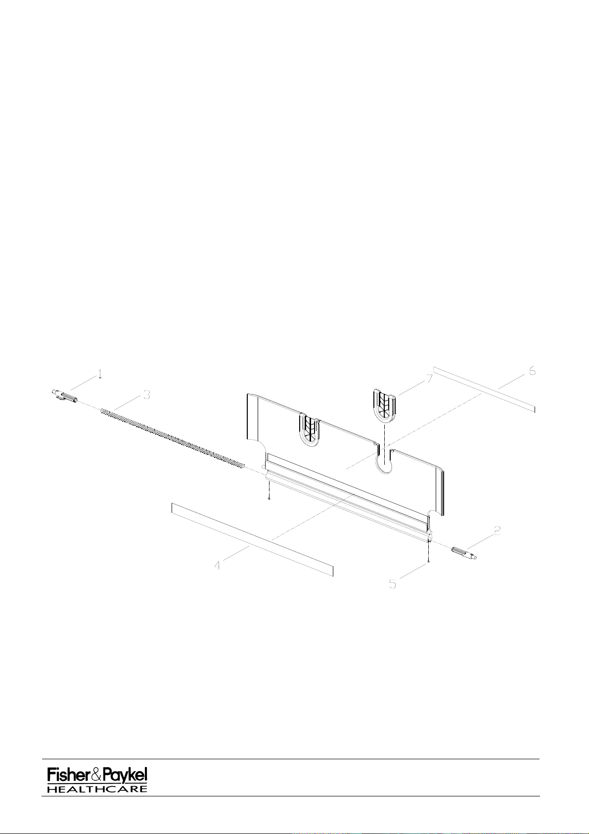
7.9.4 043042388 Bassinet (3) Side Panel Long with Inserts
Order Number and Description:
043042388 Bassinet (3) Side Spare Long with inserts
NOTE: This is a lift and fold side panel that will only fit on long bassinets version 2.5 and greater.
Bassinet (3) Side Panel Long with Inserts Parts List
Item Part
Number Description
1 694042168 Axle Sliding (3)
2 694042169 Axle Sliding Machined (3)
3 661042032 Spring Bassinet Side (3) Long
4 183042047 Label Blank Side Panel (3) Long
5 614040287 Screw M3 x 4 Grub Knurled
6 183041869 Sticker X-Ray Tray Side
7 694042132 Insert Tube Holder - Bassinet side
Bassinet (3) Side Panel Long with Inserts Assembly Diagram
IW900 Series Service Manual
Manufactured Before June 2008
PART NUMBER :
ISSUE DATE :
ISSUE NUMBER :
PAGE :
185041130
November 2008
I
90
Page 91
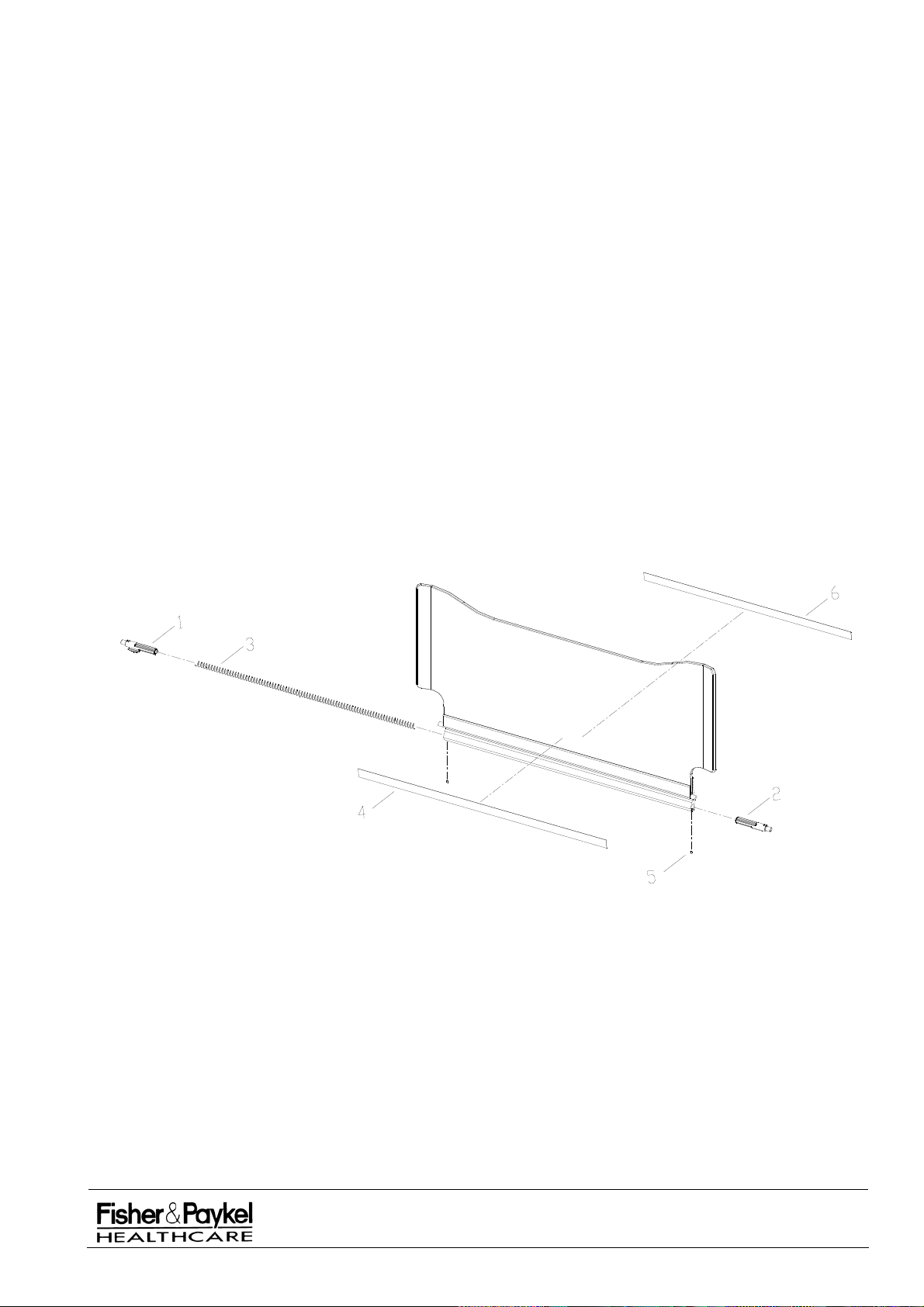
7.9.5 043042510 Bassinet (3) Side Panel High Front
Side Panel is 23cm high as measured from the bassinet & 25.5cm at the end.
Order Number and Description:
043042510
Bassinet (3) Side Panel High Front - Spare
NOTE: This is a lift and fold side panel that will only fit on bassinets version 2.5 and greater.
Bassinet (3) Side Panel High Front Parts List
Item Part
Number Description
1 694042168 Axle Sliding (3)
2 694042169 Axle Sliding Machined (3)
3 661042031 Spring Bassinet Side (3)
4 183042046 Label Blank Side Panel (3)
5 614040287 Screw M3 x 4 Grub Knurled
6 183041870 Sticker X-Ray Tray End
Bassinet (3) Side Panel High Front Assembly Diagram
IW900 Series Service Manual
Manufactured Before June 2008
PART NUMBER :
ISSUE DATE :
ISSUE NUMBER :
PAGE :
185041130
November 2008
I
91
Page 92
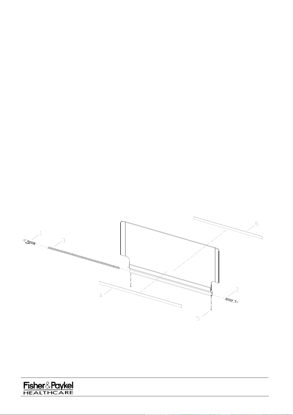
7.9.6 043042509/043042561* Bassinet (3) Side Panel High Blank (*Long)
Side panel is 25.5cm high as measured from the bassinet.
Order Number and Description:
043042509
Bassinet (3) Side Panel High Blank - Spare
043042561 Bassinet (3) Side Panel High Blank Long - Spare
NOTE: This is a lift and fold side panel that will only fit on bassinets version 2.5 and greater.
Bassinet (3) Side Panel High Blank Parts List
Item Part
Number Description
1 694042168 Axle Sliding (3)
2 694042169 Axle Sliding Machined (3)
3 661042031 Spring Bassinet Side (3)
(661042032* Spring Bassinet Side (3) Long)*
4 183042046 Label Blank Side Panel (3)
(183042047* Label Blank Side Panel (3) Long)*
5 614040287 Screw M3 x 4 Grub Knurled
6 183041869 Sticker X-Ray Tray Side
* Denotes substitute part numbers for long side panels (043042xxx) as used on the 900IW212 Long
Bassinet (3)
Bassinet (3) Side Panel High Blank Assembly Diagram
IW900 Series Service Manual
Manufactured Before June 2008
PART NUMBER :
ISSUE DATE :
ISSUE NUMBER :
PAGE :
185041130
November 2008
I
92
Page 93
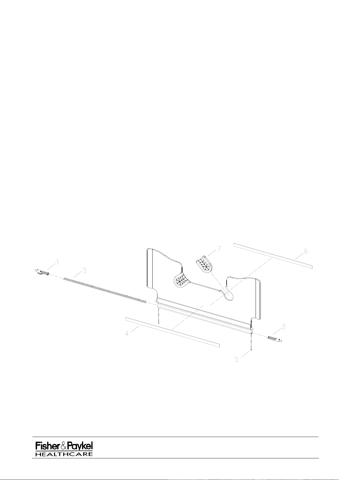
7.9.7 043042511 Bassinet (3) Side Panel High Back with Inserts
Order Number and Description:
043042511 Bassinet (3) Side Panel High Back with Inserts - Spare
NOTE: This is a lift and fold side panel that will only fit on bassinets version 2.5 and greater.
Bassinet (3) Side Panel High Back Parts List
Item Part
Number Description
1 694042168 Axle Sliding (3)
2 694042169 Axle Sliding Machined (3)
3 661042031 Spring Bassinet Side (3)
4 183042046 Label Blank Side Panel (3)
5 614040287 Screw M3 x 4 Grub Knurled
6 183041870 Sticker X-Ray Tray End
7 694042132 Insert Tube Holder - Bassinet side
Bassinet (3) Side Panel High Back Assembly Diagram
IW900 Series Service Manual
Manufactured Before June 2008
PART NUMBER :
ISSUE DATE :
ISSUE NUMBER :
PAGE :
185041130
November 2008
I
93
Page 94
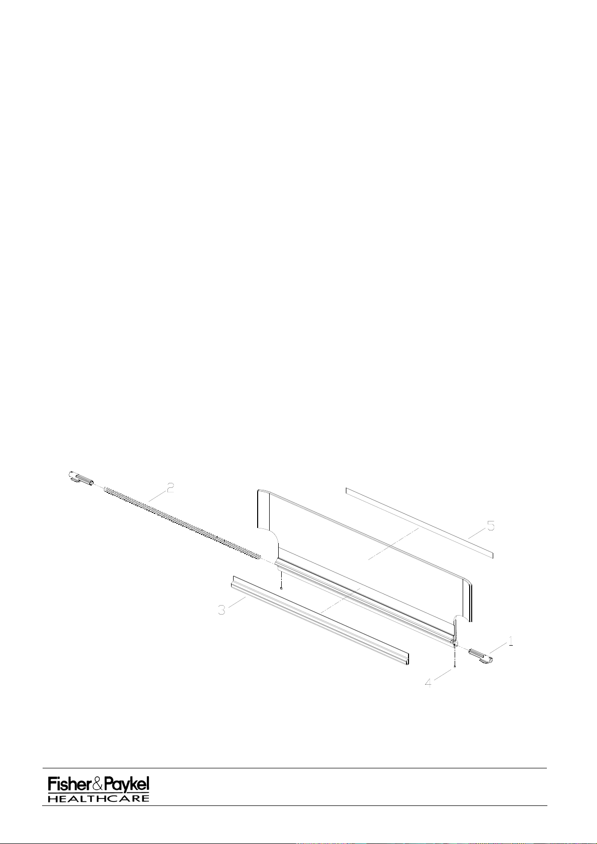
7.9.8 043042201/043042202* Bassinet (2) Side Panel with Seal (*Long)
Order Number and Description:
043042201 Bassinet (2) Side with Seal - Spare
043042202 Bassinet (2) Side Long with Seal - Spare
NOTE: These are hands free side panels designed for version 2.0 bassinets with high profile corner
caps (694042167) containing CornerGrip Tube holders (694042133) and a plastic underlay
(254040071).
Bassinet (2) Side Panel Parts List
Item Part
Number Description
1 693041415 Axle Sliding
2 662040057 Spring Side Bassinet IW2G
(662040068* Spring Side Bassinet Long)*
3 693042012 Extrusion damper/seal
(693042018* Extrusion damper/seal – long)*
4 614040287 Screw M3 x 4 Grub Knurled
5 183041869 Sticker X-Ray Tray Side
183041870** Sticker X-Ray Tray End**
* Denotes substitute part numbers for long side panels (043042202) as used on the 900IW212 Long
Bassinet
** Supplied with 043042201 spare side panels only.
Bassinet (2) Side Panel Assembly Diagram
IW900 Series Service Manual
Manufactured Before June 2008
PART NUMBER :
ISSUE DATE :
ISSUE NUMBER :
PAGE :
185041130
November 2008
I
94
Page 95
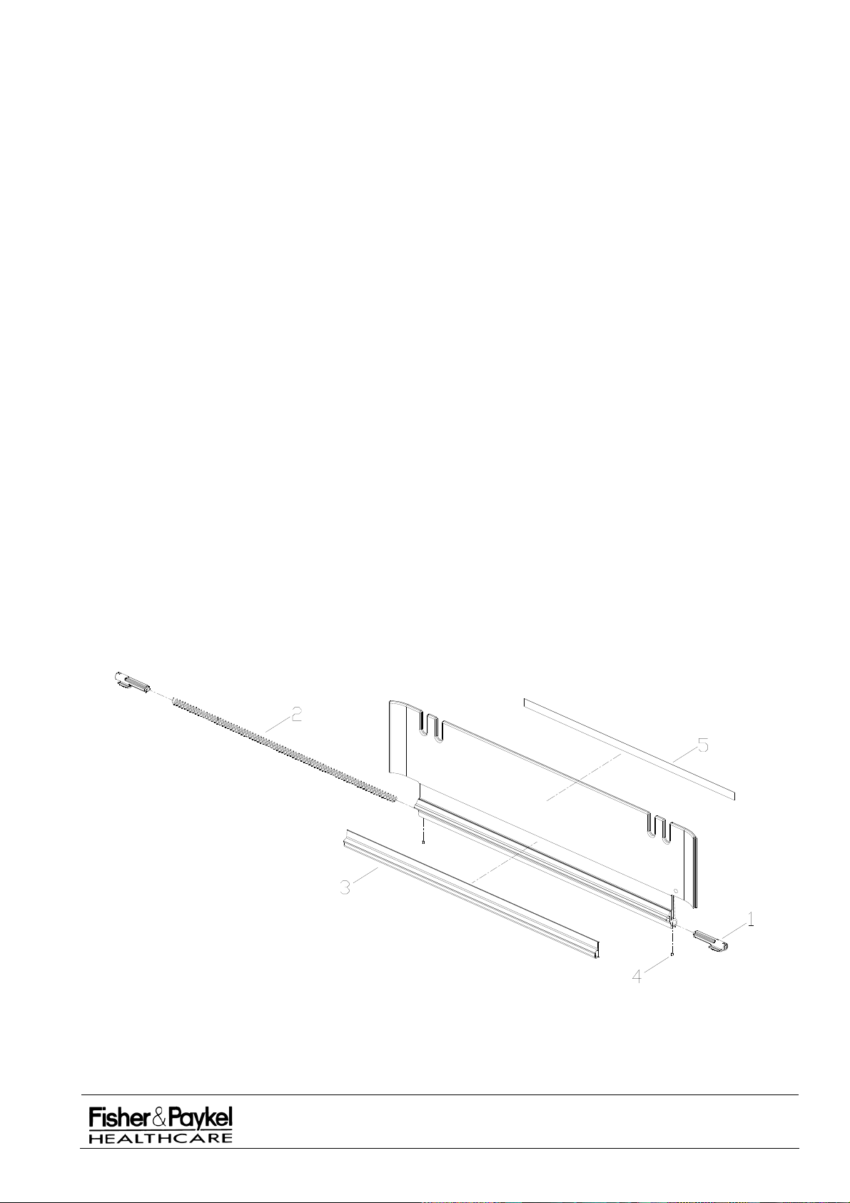
7.9.9 043042096/043042095* Bassinet Side Panel with Seal (*Long) Order Number and Description: 043042096
Bassinet Side with Seal - Spare
043042095 Bassinet Side Long with Seal - Spare
NOTE: These are hands free side panels designed for version 2.0 bassinets with standard corner caps
(641040819) and a plastic mattress underlay (254040071). They include a Santoprene extrusion
sealing strip. These side panels are NOT suitable for version 1.0 bassinets with fabric underlays
(254040068).
Bassinet Side Panel Parts List
Item Part Number Description
1 693041415 Axle Sliding
2 662040057 Spring Side Bassinet IW2G
(662040068* Spring Side Bassinet Long)*
3 693042012 Extrusion damper/seal
(693042018* Extrusion damper/seal – long)*
4 614040287 Screw M3 x 4 Grub Knurled
5 183041869 Sticker X-Ray Tray Side
183041870** Sticker X-Ray Tray End**
* Denotes substitute part numbers for long side panels (043042095) as used on the 900IW212 Long
Bassinet
** Supplied with 043042096 spare side panels only.
Bassinet Side Panel Assembly Diagram
IW900 Series Service Manual
Manufactured Before June 2008
PART NUMBER :
ISSUE DATE :
ISSUE NUMBER :
PAGE :
185041130
November 2008
I
95
Page 96
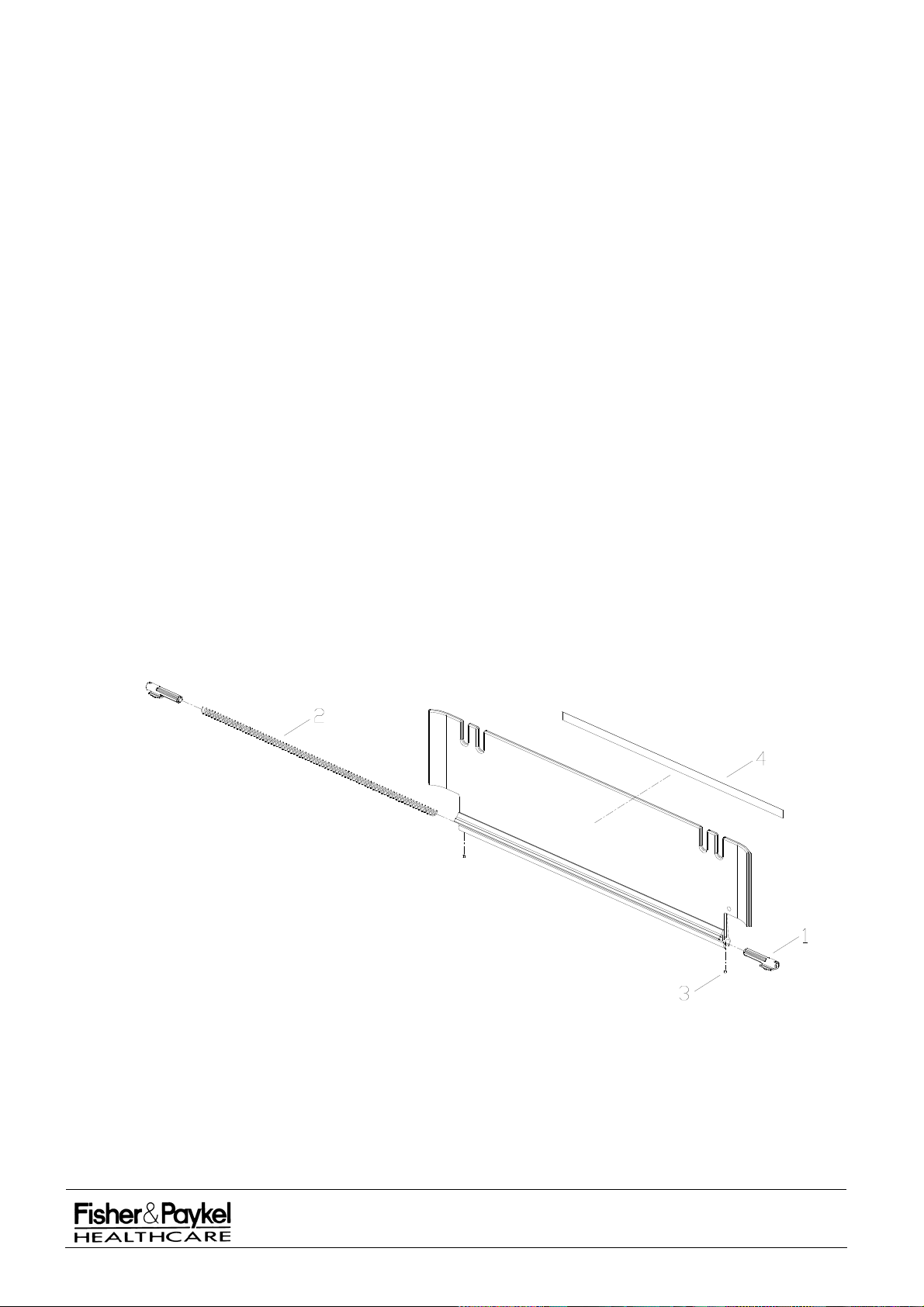
7.9.10 043041062/043041332* Bassinet Side Panel No Seal (*Long) Order Number and Description: 043041062
Bassinet Side No Seal Spare
043041332 Bassinet Side Long No Seal Spare
NOTE: These are hands free side panels designed for version 1.0 bassinets which have standard
corner caps (641040819) and a fabric underlay (254040068).
Bassinet Side No Seal Parts List
Item Part
Number Description
1 693041415 Axle Sliding
2 662040057 Spring Side Bassinet IW2G
(662040068* Spring Side Bassinet Long)*
3 614040287 Screw M3 x 4 Grub Knurled
4 183041869 Sticker X-Ray Tray Side
183041870** Sticker X-Ray Tray End**
* Denotes substitute part number for long side panels (043041332) as used on the 900IW212 Long
Bassinet
** Supplied with 043041062 spare side panels only.
Bassinet Side No Seal Assembly Diagram
IW900 Series Service Manual
Manufactured Before June 2008
PART NUMBER :
ISSUE DATE :
ISSUE NUMBER :
PAGE :
185041130
November 2008
I
96
Page 97
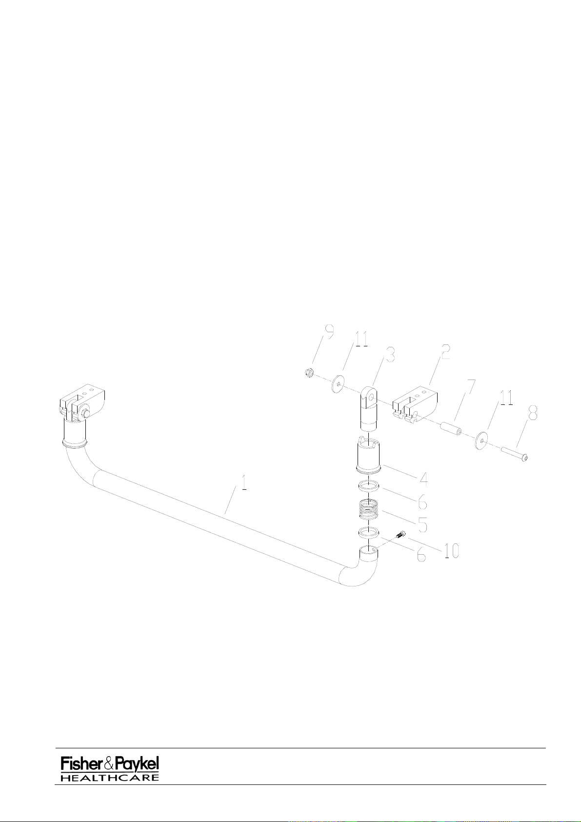
7.10 043042190 Bassinet Transport Handle Assembly
The transport handle can only be fitted to CosyCot models with bassinets versions 2.5 and greater.
7.10.1 Bassinet Transport Handle Parts List
Item Part
Number Description
1 642042030 Handle Tubular SS
2 642042033 Bracket Hinge Handle
3 642042031 Plug Hinge Handle SS
4 642042032 Collar Release Handle SS
5 661042028 Spring Push Handle
6 694042143 Bush Acetal Slider Handle
7 694042144 Bush Acetal Hinge Handle
8 614042005 Screw M6 x 40 Button Head SS
9 621040521 Nut M6 Dome Brass Chrome Plated
10 614042007 Screw M4 x 8 Low Profile
11 694042180 Washer Acetal Hinge Handle
Bassinet Transport Handle Assembly Diagram
IW900 Series Service Manual
Manufactured Before June 2008
PART NUMBER :
ISSUE DATE :
ISSUE NUMBER :
PAGE :
185041130
November 2008
I
97
Page 98

7.11 Bassinet Arms and Brake Assembly
Manufactured from February 2004
7.11.1 Bassinet Arms and Brake Assembly Parts List
Item Part
Number Description
1 694042307 Lid Storage Drawer
2 64242076 Bush Bassinet
3 642042065 Arm Warmer – Left
4 614040254 Screw M6x10 Allen S/S Button HD
5 614042335 Bolt Shoulder M8x10x16 ZP
6 622040153 Washer M6x32 S/S
7 621040524 Nut M6 Nyloc ZPS
8 642042075 Brace - Arm Warmer
9 642042074 Rod Brake Actuator
10 642042071 Spacer - Brake Cable
11 661042045 Cable Brake – Std Bassinet
661042046* Cable Brake – Long Bassinet*
12 642042073 Block – Brake Support
13 621040506 Nut M3 Nyloc
14 331042074 Heatshrink Tubing DWTC Clear
15 661042051 Ball Stop Plastic
16 614042333 Screw M6x35 CSK HD S/S Allen
17 642042066 Arm Warmer – Right
18 614040230 Screw M6x16 Allen S/S Butn HD
19 614040309 Screw M8x20 Cap Low Profile
20 642042072 Bracket Brake Ballstop Support
21 614040036 Screw M3x12 Pan Pozi ZN/ST
22 621042016 Pin Bissell Dia. 4x8 S/S
23 642042091 Safety Guard – Brake Rack
24 642042070 Spacer Block – Brake Rack
25 188042001 Tape 3M VHB9473 12.7x54.8m
26 661042055 Pin Dowel Dia. 6x50 S/S
27 610042037 Screw M4x16 CSK Phlps SS
28 642042080 Brake Rack – Fixed Section
29 614040336 Screw M5x50 Cap SS
30 642042081 Brake Rack – Moveable Section
31 661042049 Rollpin Dia 3x12 Bissel SS
32 621042011 Washer M10x21x1.25 Flat SS
33 661042047 Spring Bassinet Brake
34 610042036 Screw M4x10 Allen HD SS
35 614040213 Screw M6x40 CSK Allen Head S/S
36 642042092 Safety Guard – Brake Mechanism
37 614042332 Screw M6x20 Allen S/S Butn HD
* Denotes substitute part number for long bassinets
IW900 Series Service Manual
Manufactured Before June 2008
PART NUMBER :
ISSUE DATE :
ISSUE NUMBER :
PAGE :
185041130
November 2008
I
98
Page 99
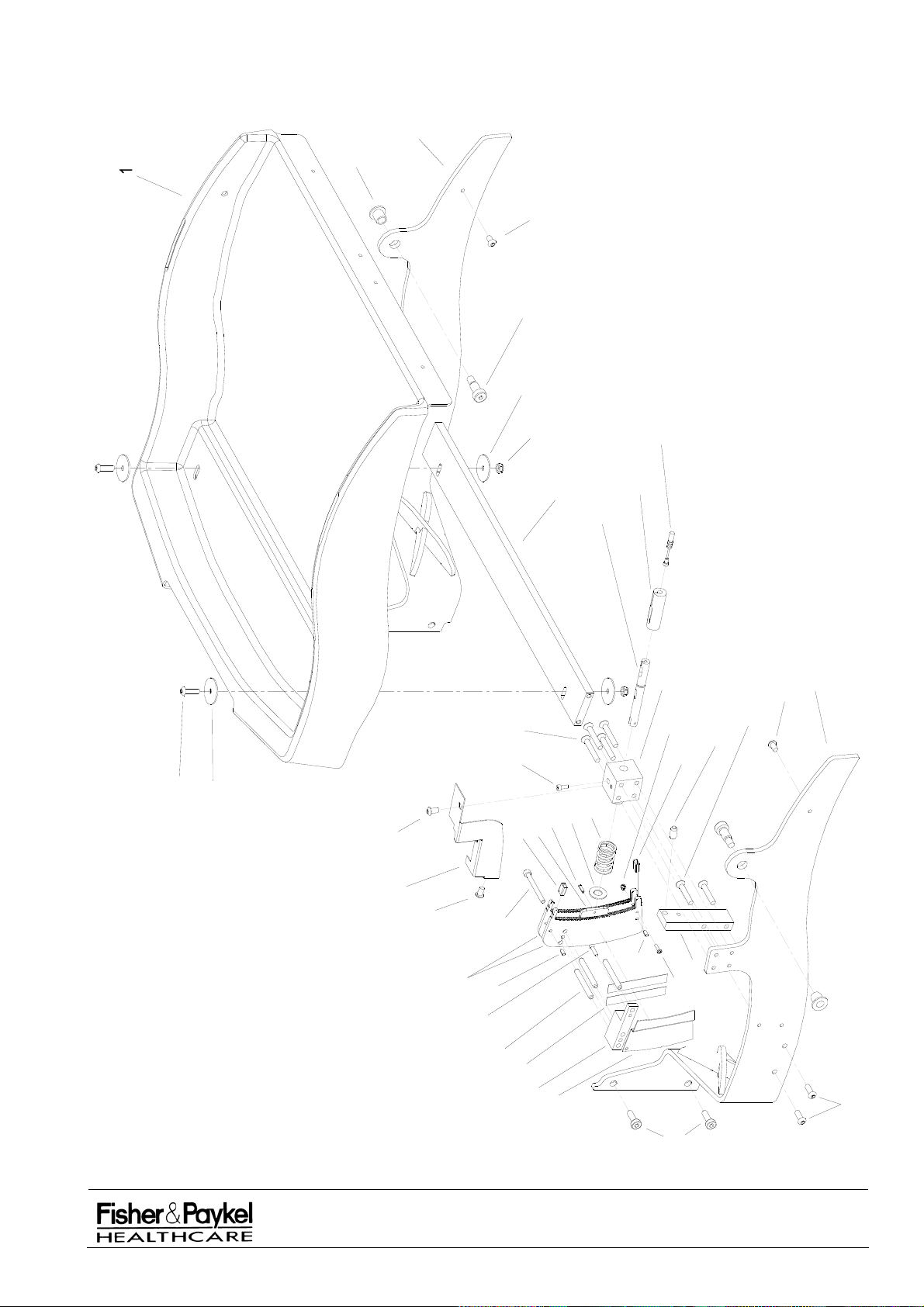
7.11.2 Bassinet Arms and Brake Assembly Diagram
3
2
4
5
6
37
7
8
11
10
9
12
35
13
34
6
30
4
14
31
32
33
14
16
15
17
4
36
4
29
28
22
22
20
21
27
26
25
24
23
19
IW900 Series Service Manual
Manufactured Before June 2008
PART NUMBER :
ISSUE DATE :
ISSUE NUMBER :
PAGE :
185041130
November 2008
18
I
99
Page 100
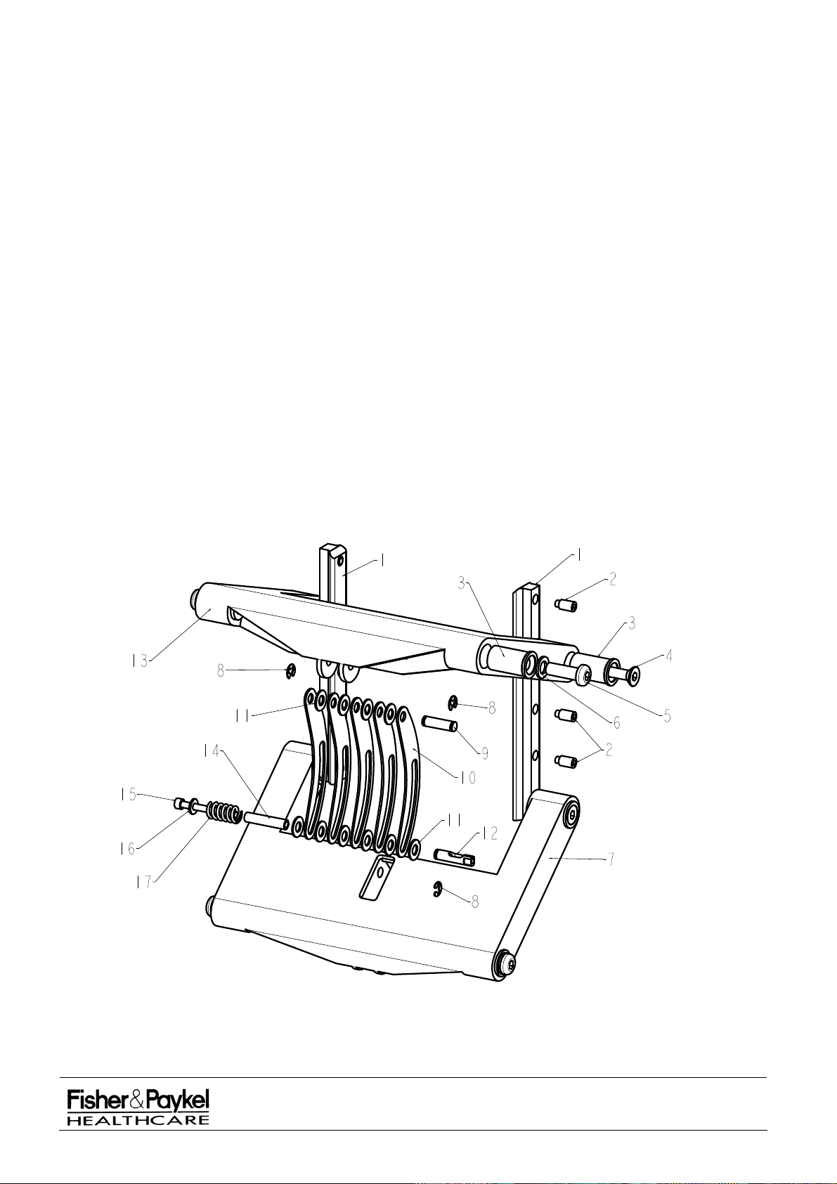
7.12 Bassinet Tilt Link Assembly
Manufactured from Jan 1997 to February 2004
7.12.1 Bassinet Tilt Link Assembly Parts List
Item Part
Number Description
1 641040738 Extrusion Slider Dovetail 0.2m
2 614040326 Screw M8 x 16 Grub Hex Dog Pnt
3 653040123 Bush M10 x 20 x 35
4 614040335 Screw M8 x 50 CSK Allen SS304
5 614040337 Screw M10 x 30 Allen SS Button Head
6 622040163 Washer M10 x 18 x 1.6 Flat SS
7 693040756 Link 4 Bar Lower Column IW2G
8 625060032 Circlip Ellison E Type 6mm SS
9 651040216 Pin M8 x 28 SS
10 641040802 Slider Tilt Brake SS
11 100556 Washer M8 x 17 Flat SS304
12 651040215 Actuator Brake Bassinet Tilt Brass
13 693040755 Link 4 Bar Upper Column IW2G
14 693041432 Spacer Acetal 8 x 5 x 37mm
15 614040336 Screw M5 x 50 Cap SS
16 622040508 Washer M5 x 12 OD 1.2mm Thick ZP
17 662050071 Spring Bassinet Tilt
7.12.2 Bassinet Tilt Link Assembly Diagram
IW900 Series Service Manual
Manufactured Before June 2008
PART NUMBER :
ISSUE DATE :
ISSUE NUMBER :
PAGE :
185041130
November 2008
I
100
 Loading...