

Page 1

Instruction Manual
D102030X012
Fisherr SS-83 Angle Valve
Contents
Introduction 1.................................
Scope of Manual 1.............................
Description 1.................................
Specifications 1...............................
Installation 2..................................
Maintenance 3.................................
Introduction
SS-83 Valve
March 2013
Packing Lubrication 4..........................
Packing Maintenance 5.........................
Replacing Packing 7........................
Trim Maintenance 9...........................
Parts Ordering 10...............................
Parts List 11...................................
Scope of Manual
This instruction manual includes installation, maintenance, and parts information for the Fisher SS-83 angle valve
(figure 1). Refer to separate manuals for instructions covering the actuator and accessories.
Do not install, operate, or maintain an SS-83 valve without being fully trained and qualified in valve, actuator, and
accessory installation, operation, and maintenance. To avoid personal injury or property damage, it is important to
carefully read, understand, and follow all the contents of this manual, including all safety cautions and warnings. If you
have any questions about these instructions, contact your Emerson Process Management sales office before
proceeding.
Description
The SS-83 is an integral bonnet angle control valve. It is designed for handling highly corrosive fluids and is usually
mounted on a tank. Body sizes refer to nominal inlet and outlet dimensions (for example, a 4 x 6 body has an NPS 4
nominal inlet and an NPS 6 nominal outlet).
Specifications
Some specifications for this valve can be found on the valve or actuator nameplate. Other specifications and limits
were specified when you ordered this valve. If you are not sure what the specifications and limits for this valve are,
contact your Emerson Process Management sales office. Specify the valve serial number and any other information
about the valve.
www.Fisher.com
Page 2

SS-83 Valve
March 2013
Instruction Manual
D102030X012
Installation
WARNING
Always wear protective gloves, clothing, and eyewear when performing any installation operations to avoid personal
injury.
Personal injury or equipment damage caused by sudden release of pressure may result if the valve assembly is installed
where service conditions could exceed the limits specified when the valve was purchased or on the appropriate
nameplates. To avoid such injury or damage, provide a relief valve for over-pressure protection as required by government
or accepted industry codes and good engineering practices.
Check with your process or safety engineer for any additional measures that must be taken to protect against process
media.
If installing into an existing application, also refer to the WARNING at the beginning of the Maintenance section in this
instruction manual.
CAUTION
When ordered, the valve configuration and construction materials were selected to meet particular pressure, temperature,
pressure drop and controlled fluid conditions. Because some body/trim material combinations are limited in their pressure
drop and temperature ranges, do not apply any other conditions to the valve without first contacting your Emerson
Process Management sales office.
If hoisting the valve, use a nylon sling to protect the surfaces. Carefully position the sling to prevent damage to the actuator
tubing and any accessories. Also, take care to prevent people from being injured in case the hoist or rigging slips
unexpectedly. Be sure to use adequately sized hoists and chains or slings to handle the valve.
1. Before installing the valve, inspect the valve body cavity and associated equipment for any damage and any foreign
material.
2. Make certain the body interior is clean, that pipelines are free of foreign material, and that the valve is oriented so
that pipeline flow is in the same direction as the arrow on the side of the valve.
3. If possible, install the valve with the valve stem vertical. All valves with size 80 or larger actuators mounted between
45_ above and 45_ below horizontal should be supported. Small actuators might also need support if vibrational or
other non-gravitational forces are present. For more information on seismic considerations, consult your Emerson
Process Management sales office.
4. Use accepted piping, flange, or welding practices when installing the valve in the line. For flanged valve bodies, use
a suitable gasket between the body and pipeline flanges.
Note
For valves with a welding-end, depending on valve body materials used, post weld heat treating may be required. If so, damage to
internal elastomeric and plastic parts, as well as internal metal parts is possible. Shrink-fit pieces and threaded connections may
also loosen. In general, if post weld heat treating is to be performed, remove all trim parts. Contact your Emerson Process
Management sales office for additional information.
2
Page 3

Instruction Manual
D102030X012
SS-83 Valve
March 2013
5. With a leak-off bonnet construction, remove the pipe plug from the bonnet to hook up the leak-off piping. If
continuous operation is required during inspection or maintenance, install a three-valve bypass around the control
valve assembly.
6. If the actuator and valve are shipped separately, refer to the actuator mounting procedure in the appropriate
actuator instruction manual.
WARNING
Personal injury could result from packing leakage. Valve packing was tightened before shipment; however, the packing
might require some readjustment to meet specific service conditions.
Valves with ENVIRO-SEALt live-loaded packing or HIGH-SEAL live-loaded packing will not require this initial
re-adjustment. See the Fisher instruction manuals, ENVIRO-SEAL Packing System for Sliding-Stem Valves or HIGH-SEAL
Live-Loaded Packing System (as appropriate), for packing instructions.
Maintenance
Valve parts are subject to normal wear and must be inspected and replaced as necessary. Inspection and maintenance
frequency depends on the severity of service conditions. This section includes instructions for packing lubrication,
packing maintenance, trim maintenance, and lapping metal seats.
WARNING
Avoid personal injury or damage to property from sudden release of pressure or uncontrolled process fluid. Before starting
disassembly:
D Do not remove the actuator from the valve while the valve is still pressurized.
D Always wear protective gloves, clothing, and eyewear when performing any maintenance operations to avoid personal
injury.
D Disconnect any operating lines providing air pressure, electric power, or a control signal to the actuator. Be sure the
actuator cannot suddenly open or close the valve.
D Use bypass valves or completely shut off the process to isolate the valve from process pressure. Relieve process pressure
on both sides of the valve. Drain the process media from both sides of the valve.
D Vent the power actuator loading pressure and relieve any actuator spring precompression.
D Use lock-out procedures to be sure that the above measures stay in effect while you work on the equipment.
D The valve packing box may contain process fluids that are pressurized, even when the valve has been removed from the
pipeline. Process fluids may spray out under pressure when removing the packing hardware or packing rings, or when
loosening the packing box pipe plug.
D Check with your process or safety engineer for any additional measures that must be taken to protect against process
media.
Note
Whenever a gasket seal is disturbed by removing or shifting gasketed parts, install a new gasket upon reassembly. This is necessary
to ensure a good gasket seal because the used gasket may not seal properly.
3
Page 4
SS-83 Valve
March 2013
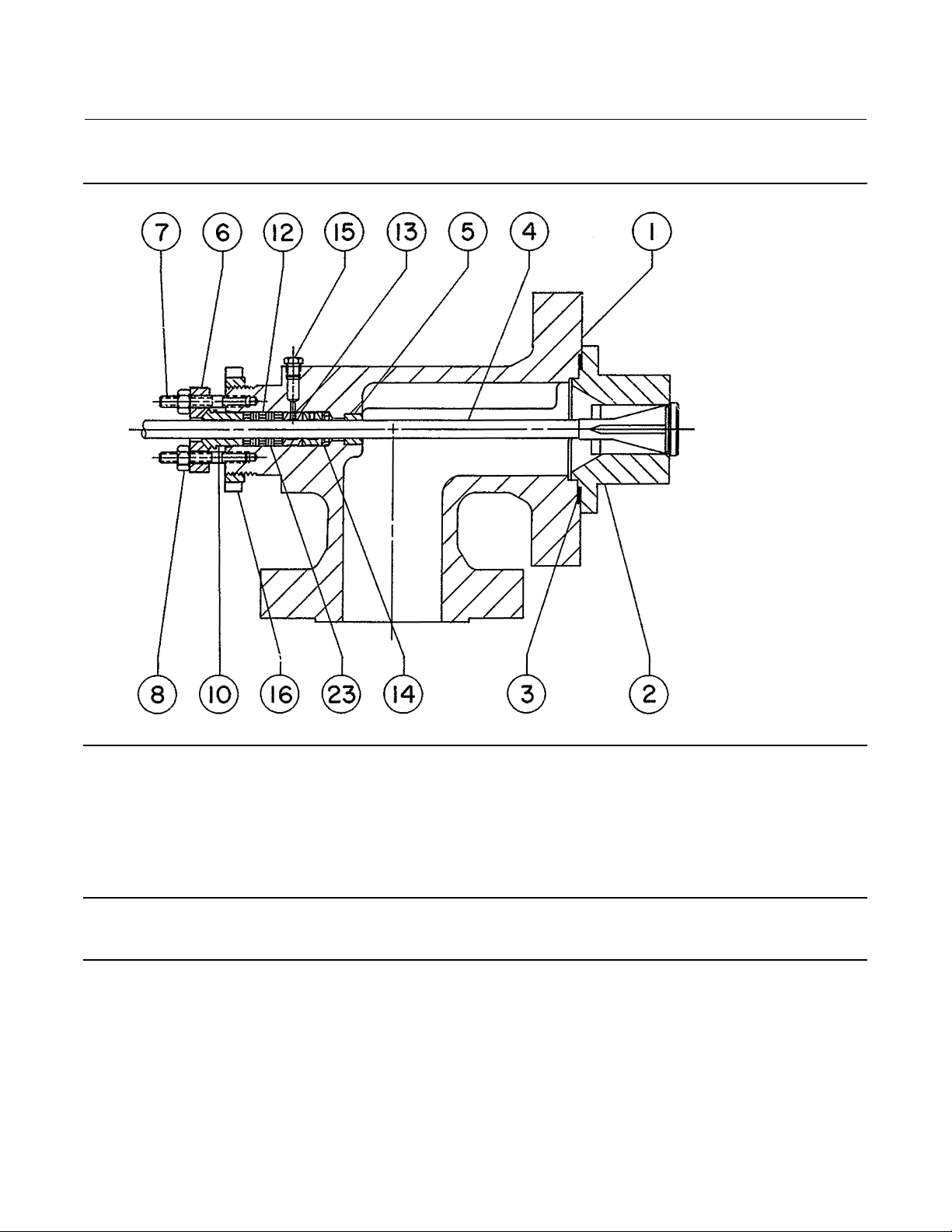
Figure 1. Fisher SS-83 Valve
Instruction Manual
D102030X012
15A1618-A
91 mm (3-9/16 INCH) YOKE BOSS
Packing Lubrication
Note
ENVIRO-SEAL or HIGH-SEAL packing does not require lubrication.
If a lubricator or lubricator/isolating valve is provided for PTFE/composition or other packings that require lubrication,
it will be installed in place of the pipe plug (key 15). Use a good quality silicon-base lubricant. Do not lubricate packing
used in oxygen service or in processes with temperatures over 260_C(500_F). To operate the lubricator, simply turn
the cap screw clockwise to force the lubricant into the packing box. The lubricator/isolating valve operates the same
way,exceptopentheisolatingvalvebeforeturningthecapscrewandthenclosetheisolatingvalveafterlubricationis
completed.
4
Page 5

Instruction Manual
D102030X012
Figure 1. Fisher SS-83 Valve (Continued)
SS-83 Valve
March 2013
15A1619-A
5-INCH (127 mm) YOKE BOSS
Packing Maintenance
Note
For valves with ENVIRO-SEAL live-loaded packing, see the Fisher instruction manual, ENVIRO-SEAL Packing System for Sliding-Stem
Valves, for packing instructions. For valves with HIGH-SEAL live-loaded packing, see the Fisher instruction manual, HIGH-SEAL
Live-Loaded Packing System, for packing instructions.
For spring-loaded single PTFE V-ring packing, the packing spring maintains a sealing force on the packing. If leakage is
noted around the packing follower, check to be sure the shoulder on the packing follower is touching the bonnet. If
the shoulder is not touching the bonnet, tighten the packing flange nuts until the shoulder is against the bonnet. If
leakage cannot be stopped in this manner, proceed to the Replacing Packing procedure.
5
Page 6

SS-83 Valve
March 2013
Figure 1. Fisher SS-83 Valve (Continued)
Instruction Manual
D102030X012
35A8298-A
7-INCH (178 mm) YOKE BOSS
If there is undesirable packing leakage with other than spring-loaded packing, first try to limit the leakage and
establish a stem seal by tightening the packing flange nuts.
If the packing is relatively new and tight on the stem and if tightening the packing flange nuts does not stop the
leakage, the valve stem may be worn or nicked so that a seal cannot be made. The surface finish of a new valve stem is
critical for making a good packing seal. If the leakage comes from the outside diameter of the packing, the leakage
may be caused by nicks or scratches around the packing box wall. If performing any of the following procedures,
inspect the valve stem and packing box wall for nicks and scratches.
6
Page 7

Instruction Manual
D102030X012
SS-83 Valve
March 2013
CAUTION
Use care to avoid damaging gasket sealing surfaces.
The surface finish of the valve stem is critical for making a good packing seal. The seating surfaces of the valve plug and the
seat ring on a metal-seat construction are critical for tight shutoff. Assume all these parts are in good condition and protect
them accordingly, unless inspection reveals otherwise
WARNING
Refer to the warning at the beginning of the maintenance section.
Replacing Packing
Key numbers are shown in figure 1 except where indicated.
1. Isolatethecontrolvalvefromthelinepressure,releasepressure from both sides of the valve, and drain the process
media from both sides of the valve. If using a power actuator, also shut off all pressure lines to the power actuator,
releaseallpressurefromtheactuatorandrelievespringcompressionfromtheactuator.Uselock-outproceduresto
be sure that the above measures stay in effect while you work on the equipment.
2. Disconnect the operating lines from the actuator and any leak-off piping from the valve.
3. Being careful to avoid damage to the valve plug (key 4), remove the valve from the line. Disconnect the stem
connector, and then remove the actuator from the valve by unscrewing the yoke locknut (key 16) or the cap screws
(key 17).
4. Remove any stem connector parts or locknuts. Remove packing flange nuts, packing flange, and packing follower
(keys8,6,and10).
5. Remove the seat ring (key 2) and the valve plug and stem assembly (key 4) through the bottom of the valve body.
Set removed parts on a protective surface to prevent damage to gasket or seating surfaces.
6. Being careful to avoid damaging the packing box wall, remove all packing parts with a formed wire hook.
7. Clean the packing box and the metal packing box parts. When installing new packing, refer to figure 2 for the order
of placement of packing box parts.
8. Clean the gasketed surfaces and install a new gasket (key 3). Install the seat ring (key 2) and slide the plug and stem
assembly (key 4) back into the valve body.
9. Slide the packing box parts over the stem and into the packing box. Place a smooth-edged pipe over the valve stem
and gently tap each soft packing part into the packing box, being sure that air is not trapped between adjacent soft
parts. Refer to figure 2 for the order of placement of parts. Contact your Emerson Process Management sales office
if your packing is not shown in figure 2.
Key numbers are shown in figure 1 except where indicated.
10. Install the packing follower, packing box flange, and nuts. Tighten the packing flange nuts snuggly.
11. Before putting the valve in service, cycle the valve until packing friction is reduced to an acceptable level.
12. Install the actuator according to instructions in the appropriate actuator instruction manual. Install the valve back
in the line.
7
Page 8

SS-83 Valve
March 2013
Instruction Manual
D102030X012
Figure 2. Typical Packing for Fisher SS-83 Valves
12A8160-A
PTFE V-RING
SINGLE PACKING
12A7839-A
Sht 1
PTFE V-RING
DOUBLE PACKING
UPPER WIPER (KEY 12)
PACKING FOLLOWER
(KEY 13)
FEMALE ADAPTOR
(KEY 32)
V-RING (KEY 7)
MALE
ADAPTOR (KEY 31)
WASHER (KEY 10)
SPRING (KEY 8)
PACKING BOX RING
(KEY 11)
LOWER WIPER
(KEY 30)
UPPER WIPER (KEY 12)
PACKING FOLLOWER
(KEY 13)
FEMALE ADAPTOR
(KEY 32)
V-RING (KEY 7)
MALE ADAPTOR
(KEY 31)
LANTERN RING
(KEY 8)
PACKING BOX RING
(KEY 11)
LOWER WIPER
(KEY 30)
KEY 6
1
14A3412-B
GRAPHITE LAMINATE AND FILAMENT
SINGLE PACKING
KEY 6
1
1
14A3414-B
GRAPHITE LAMINATE AND
FILAMENT DOUBLE PACKING
PACKING ARRANGEMENTS FOR 1-1/4 INCH (31.8 mm) VALVE STEMS
PACKING FOLLOWER
(KEY 13)
GRAPHITE LAMINATE
PACKING RING (KEY 7)
2
GRAPHITE FILAMENT
PACKING RING (KEY 9)
3
LANTERN RING
(KEY 8)
PACKING BOX RING
(KEY 11)
PACKING FOLLOWER
(KEY 13)
GRAPHITE LAMINATE
PACKING RING (KEY 7)
2
GRAPHITE FILAMENT
PACKING RING (KEY 9)
3
LANTERN RING
(KEY 8)
PACKING BOX RING
(KEY 11)
12A8163-A
13A0112-A
GRAPHITE/COMPOSITION
DOUBLE PACKING
PTFE/COMPOSITION
DOUBLE PACKING
UPPER WIPER (KEY 12)
PACKING FOLLOWER
(KEY 13)
PACKING RING
(KEY 7)
PACKING RING
(KEY 7)
LANTERN RING
(KEY 8)
PACKING BOX RING
(KEY 11)
UPPER WIPER (KEY 12)
PACKING FOLLOWER
(KEY 13)
PACKING RING
(KEY 7)
LANTERN RING
(KEY 8)
PACKING BOX RING
(KEY 11)
PACKING
FOLLOWER
(KEY 13)
GRAPHITE
LAMINATE
PACKING RING
1
14A3419-B 14A3418-A
(KEY 7)
GRAPHITE
FILAMENT
PACKING RING
(KEY 9)
LANTERN RING
(KEY 8)
PACKING
BOX RING
(KEY 11)
GRAPHITE LAMINATE AND FILAMENT
SINGLE PACKING
C0634-1
NOTES:
1
0.004 INCH (0.102 mm) THICK SACRIFICIAL ZINC WASHERS. USE ONLY ONE BELOW EACH GRAPHITE LAMINATE RING.
2
HAS THE APPEARANCE OF FLAT WASHERS PRESSED TOGETHER.
3
HAS THE APPEARANCE OF A WOVEN OR BRAIDED RING.
PACKING ARRANGEMENTS FOR 50.8 mm (2-INCH) VALVE STEMS
1
2
3
1
GRAPHITE LAMINATE AND FILAMENT
DOUBLE PACKING
PACKING
FOLLOWER
(KEY 13)
GRAPHITE
LAMINATE
PACKING RING
(KEY 7)
GRAPHITE
FILAMENT
PACKING RING
(KEY 9)
LANTERN RING
(KEY 8)
8
2
3
PACKING
BOX RING
(KEY 11)
13A0029-A
GRAPHITE/COMPOSITION AND
PTFE/COMPOSITION DOUBLE PACKING
UPPER WIPER (KEY 12)
PACKING FOLLOWER
(KEY 13)
PACKING RING
(KEY 7)
LANTERN RING
(KEY 8)
PACKING BOX RING
(KEY 11)
Page 9

Instruction Manual
D102030X012
SS-83 Valve
March 2013
13. For spring-loaded PTFE V-ring packing, tighten the packing flange nuts until the shoulder on the packing follower
contacts the bonnet.
For graphite packing, tighten the packing flange nuts to the maximum recommended torque shown in table 1.
Then loosen the packing flange nuts, and retighten them to the recommended minimum torque shown in table 1. If
the stem diameter of your valve is not shown in the table, contact your Emerson Process Management sales office.
For ENVIRO-SEAL or HIGH-SEAL live-loaded packing, refer to the note at the beginning of the Maintenance section.
For other types of packing, contact your Emerson Process Management sales office.
14. Mount the actuator on the valve assembly and reconnect the actuator and valve stem according to the procedure
in the appropriate actuator instruction manual.
Table 1. Packing Flange Nut Torque for Graphite Packing
STEM DIAMETER
mm Inches NSm LbfSIn NSm LbfSIn
19.1 3/4
25.4 1
31.8 1-1/4
50.8 2
PRESSURE RATING
CL150
CL300
CL600
CL900
CL150
CL300
CL600
CL900
CL150
CL300
CL600
CL900
CL600
CL900
MINIMUM TORQUE MAXIMUM TORQUE
11.2
15.0
20.6
25.0
19.1
25.5
35.1
42.5
26.9
35.9
49.4
59.8
63.8
77.3
99
133
182
221
169
226
310
376
238
318
437
530
565
684
16.9
22.5
30.9
37.5
28.7
38.3
52.6
63.8
40.4
53.8
74.0
89.7
95.7
116
149
199
274
332
254
339
466
564
357
477
655
794
847
1,026
Trim Maintenance
WARNING
Refer to the warning at the beginning of the maintenance section.
CAUTION
Use care to avoid damaging gasket sealing surfaces.
The surface finish of the valve stem is critical for making a good packing seal. The seating surfaces of the valve plug and the
seat ring on a metal-seat construction are critical for tight shutoff. Assume all these parts are in good condition and protect
them accordingly, unless inspection reveals otherwise.
1. Isolate the valve body and actuator from all pressure. Release all pressure from the valve. Disconnect any operating
lines providing air pressure, electric power, or a control signal to the actuator. Be sure the actuator cannot suddenly
openorclosethevalve.Usebypassvalvesorcompletelyshutofftheprocesstoisolatethevalvefromprocess
pressure. Relieve process pressure from both sides of the valve. Drain the process media from both sides of the
valve.Vent the pneumatic actuator loading pressure and relieve any actuator spring precompression.Use lock-out
procedures to be sure that the above measures stay in effect while you work on the equipment.
2. Disconnect the operating lines from the actuator and any leak-off piping from the valve.
3. Being careful to avoid damage to the valve plug (key 4), remove the valve from the line. Disconnect the stem
connector, and then remove the actuator from the valve by unscrewing the yoke locknut (key 16) or the cap screws
(key 17).
9
Page 10

SS-83 Valve
March 2013
4. Remove any stem connector parts or locknuts. Loosen the packing flange nuts (key 8).
5. Remove the seat ring (key 2) and the valve plug and stem assembly (key 4) through the bottom of the valve body.
Set removed parts on a protective surface to prevent damage to gasket or seating surfaces.
6. Inspect the plug and stem assembly for nicks, scratches, scoring, or signs of galling. (If the stem is worn, packing
leakage can result.) Clean the gasketed surfaces and replace the seat ring gasket (key 3), seat ring (key 2), and valve
plug and stem assembly (key 4).
7. Tighten the packing flange nuts snuggly.
8. Before putting the valve in service, cycle the valve until packing friction is reduced to an acceptable level.
9. Install the actuator according to instructions in the appropriate actuator instruction manual. Install the valve back in
the line.
10. For spring-loaded PTFE V-ring packing, tighten the packing flange nuts until the shoulder on the packing follower
contacts the bonnet.
For graphite packing, tighten the packing flange nuts to the maximum recommended torque shown in table 1.
Then loosen the packing flange nuts, and retighten them to the recommended minimum torque shown in table 1. If
the stem diameter of your valve is not shown in the table, contact your Emerson Process Management sales office.
For ENVIRO-SEAL or HIGH-SEAL live-loaded packing, refer to the note at the beginning of the Maintenance section.
For other types of packing, contact your Emerson Process Management sales office.
11. Mount the actuator on the valve assembly and reconnect the actuator and valve stem according to the procedure
in the appropriate actuator instruction manual.
Instruction Manual
D102030X012
Parts Ordering
Eachvalveisassignedaserialnumberwhichcanbefoundonthevalveoronthenameplate.Thenameplatewill
normally be fitted to the actuator. Refer to this serial number when contacting your Emerson Process Management
sales office for technical assistance. When ordering replacement parts refer to this serial number and give the part
description from the following parts list.
WARNING
Use only genuine Fisher replacement parts. Components that are not supplied by Emerson Process Management should
not, under any circumstances, be used in any Fisher valve, because they may void your warranty, might adversely affect the
performance of the valve, and could cause personal injury and property damage.
10
Page 11

Instruction Manual
D102030X012
Parts List
Note
For part numbers not shown, contact your Emerson Process
Management sales office.
Valve(Seefigure2forPacking
Parts)
Key Description
1ValveBody
2SeatRing
3* Seat Ring Gasket
4* Valve Plug and Stem Assembly
5 Bushing
6 Packing Box Flange
7 Packing Box Stud
8 Packing Box Nut
10 Packing Follower (also see figure 2)
12* PackingRing(alsoseefigure2)
13 Lantern Ring (also see figure 2)
14 Packing Box Ring (also see figure 2)
15 Pipe Plug
16 Yoke Locknut
17 Cap Screw
23* PackingRing(alsoseefigure2)
SS-83 Valve
March 2013
*Recommended spare parts
11
Page 12

SS-83 Valve
March 2013
Instruction Manual
D102030X012
Neither Emerson, Emerson Process Management, nor any of their affiliated entities assumes responsibility for the selection, use or maintenance
of any product. Responsibility for proper selection,use, and maintenance of any product remains solely withthe purchaser and end user.
Fisher and ENVIRO-SEAL are marks owned by one of the companies in the Emerson Process Management business unit of Emerson Electric Co. Emerson
Process Management, Emerson, and the Emerson logo are trademarks and service marks of Emerson Electric Co. All other marks are the property of their
respective owners.
The contents of this publication are presented for informational purposes only, and while every effort has been made to ensure their accuracy, they arenot
to be construed as warranties or guarantees, express or implied, regarding the products or services described herein or their use or applicability. All sales are
governed by our terms and conditions, which are available upon request. We reserve the right to modify or improve the designs or specifications of such
products at any time without notice.
Emerson Process Management
Marshalltown, Iowa 50158 USA
Sorocaba, 18087 Brazil
Chatham, Kent ME4 4QZ UK
Dubai, United Arab Emirates
Singapore 128461 Singapore
www.Fisher.com
12
E 1995, 2013 Fisher Controls International LLC. All rights reserved.
 Loading...