

Page 1

Instruction Manual
D100381X012
HS Valve
June 2019
Fisher™ HS Control Valve - OBS Valve
Contents
Introduction 1.................................
Safety Instructions 1............................
Specifications 2................................
Inspection and Maintenance Schedules 2...........
Parts Ordering 2................................
Installation 3..................................
Maintenance 4.................................
Latest Published Instruction Manual 5..............
Introduction
The product covered in this document is no longer in production. This document, which includes the latest published
version of the instruction manual, is made available to provide updates of newer safety procedures. Be sure to follow
the safety procedures in this supplement as well as the specific instructions in the included instruction manual.
Part numbers in the included instruction manual should not be relied on to order replacement parts. For replacement
parts, contact your Emerson sales office
For more than 20 years, Fisher products have been manufactured with asbestos‐free components. The included
manual might mention asbestos containing parts. Since 1988, any gasket or packing which may have contained some
asbestos, has been replaced by a suitable non‐asbestos material. Replacement parts in other materials are available
from your sales office.
.
Safety Instructions
Please read these safety warnings, cautions, and instructions carefully before using the product.
These instructions cannot cover every installation and situation. Do not install, operate, or maintain this product
without being fully trained and qualified in valve, actuator and accessory installation, operation and maintenance. To
avoid personal injury or property damage it is important to carefully read, understand, and follow all of the contents of
this manual, including all safety cautions and warnings. If you have any questions about these instructions, contact
your Emerson sales office before proceeding.
www.Fisher.com
Page 2

HS Valve
June 2019
Instruction Manual
D100381X012
Specifications
This product was intended for a specific range of service conditions‐‐pressure, pressure drop, process and ambient
temperature, temperature variations, process fluid, and possibly other specifications. Do not expose the product to
service conditions or variables other than those for which the product was intended. If you are not sure what these
conditions or variables are, contact your Emerson sales office
other pertinent information that you have available.
for assistance. Provide the product serial number and all
Inspection and Maintenance Schedules
All products must be inspected periodically and maintained as needed. The schedule for inspection can only be
determined based on the severity of your service conditions. Your installation might also be subject to inspection
schedules set by applicable governmental codes and regulations, industry standards, company standards, or plant
standards.
In order to avoid increasing dust explosion risk, periodically clean dust deposits from all equipment.
When equipment is installed in a hazardous area location (potentially explosive atmosphere), prevent sparks by proper
tool selection and avoiding other types of impact energy. Control Valve surface temperature is dependent upon
process operating conditions.
WARNING
Control valve surface temperature is dependent upon process operating conditions. Personal injury or property damage,
caused by fire or explosion, can result if the valve body surface temperature exceeds the acceptable temperature for the
hazardous area classification. To avoid an increase of instrumentation and/or accessory surface temperature due to process
operating conditions, ensure adequate ventilation, shielding, or insulation of control valve components installed in a
potentially hazardous or explosive atmosphere.
Parts Ordering
Whenever ordering parts for older products, always specify the serial number of the product and provide all other
pertinent information that you can, such as product size, part material, age of the product, and general service
conditions. If you have modified the product since it was originally purchased, include that information with your
request.
WARNING
Use only genuine Fisher replacement parts. Components that are not supplied by Emerson Automation Solutions should
not, under any circumstances, be used in any Fisher product, because they may void your warranty, might adversely affect
the performance of the product, and could cause personal injury and property damage.
2
Page 3

Instruction Manual
D100381X012
HS Valve
June 2019
Installation
WARNING
D Personal injury or equipment damage caused by sudden release of pressure or bursting of parts may result if the valve
assembly is installed where service conditions could exceed the limits given in the applicable product literature, the
limits on the appropriate nameplates, or the mating pipe flange rating. Use pressure‐relieving devices as required by
government or relevant industry codes and good engineering practices. If you cannot determine the ratings and limits
for this product, contact your Emerson sales office
D To avoid personal injury, always wear protective gloves, clothing, and eyewear when performing any installation
operations.
D To avoid personal injury or property damage, use proper lifting and rigging practices while lifting, installing or
removing the valve assembly. Be sure to use lifting and rigging equipment properly sized and selected for the weight
and configuration of the valve assembly or component being lifted.
D Personal injury could result from packing leakage. Valve packing was tightened before shipment; however, the packing
might require some readjustment to meet specific service conditions.
D Many rotary shaft valves are not necessarily grounded to the pipeline when installed in a flammable, hazardous, oxygen
service, or explosive atmospheres. An explosion is possible, due to the discharge of static electricity from the valve
components. To avoid personal injury or property damage, make sure that the valve is grounded to the pipeline before
placing the control valve assembly into service. Use and maintain alternate shaft‐to‐body bonding, such as a
shaft‐to‐body bonding strap assembly.
D Rotary shaft valves are designed and intended for installation between flanges. Personal injury or property damage may
result from improper installation. To avoid personal injury or property damage caused by the sudden release of
pressure or bursting of parts, do not use or install rotary shaft valves (including single lug constructions) for dead‐end
service.
D Check with your process or safety engineer for any additional measures that must be taken to protect against process
media.
D If installing into an existing application, also refer to the WARNING in the Maintenance section.
D When ordered, the valve configuration and construction materials were selected to meet particular pressure,
temperature, pressure drop, and controlled fluid conditions. Responsibility for the safety of process media and
compatibility of valve materials with process media rests solely with the purchaser and end‐user. To avoid possible
personal injury and because some valve/trim material combinations are limited in their pressure drop and temperature
ranges, do not apply any other conditions to the valve without first contacting your Emerson sales office.
before proceeding.
CAUTION
D Ensure that the valve and adjacent pipelines are free of foreign material that could damage the valve seating surfaces.
3
Page 4

HS Valve
June 2019
Instruction Manual
D100381X012
Maintenance
WARNING
Avoid personal injury or property damage from sudden release of process pressure or bursting of parts. Before performing
any maintenance operations:
D Always wear protective gloves, clothing, and eyewear.
D Disconnect any operating lines providing air pressure, electric power, or a control signal to the actuator. Be sure the
actuator cannot suddenly open or close the valve.
D Use bypass valves or completely shut off the process to isolate the valve from process pressure.
D Do not remove the actuator while the valve is pressurized.
D Relieve process pressure from both sides of the valve. Drain the process media from both sides of the valve.
D Vent the pneumatic actuator loading pressure and relieve any actuator spring pre‐compression.
D Use lock‐out procedures to be sure that the above measures stay in effect while you work on the equipment.
D The valve packing box might contain process fluids that are pressurized, even when the valve has been removed from the
pipeline. Process fluids might spray out under pressure when removing the packing hardware or packing rings, or when
loosening the packing box pipe plug. Cautiously remove parts so that fluid escapes slowly and safely.
D Many valve parts that are moving can injure you by pinching, cutting, or shearing. To help prevent such injury, stay
clear of any moving part.
D Never apply pressure to a partially assembled valve.
D To avoid personal injury or property damage caused by uncontrolled movement of a valve bonnet, loosen the bonnet by
following these instructions: Do not remove a stuck bonnet by pulling on it with equipment that can stretch or store
energy in any other manner. The sudden release of stored energy can cause uncontrolled movement of the bonnet.
Loosen bonnet nuts approximately 3 mm (0.125 inch). Then loosen the body‐to‐bonnet gasketed joint by either rocking
the bonnet or prying between the bonnet and body. Work the prying tool around the bonnet until the bonnet loosens.
If no fluid leaks from the joint, proceed with bonnet removal.
D As you remove parts, such as valve shafts, other parts, such as disks can fall from the valve body or suddenly move to
another position in the valve. To avoid injury from falling or moving parts, be sure to support parts and be sure they are
in a stable position as you disassemble the valve.
D Personal injury could result from packing leakage. Do not scratch the drive shaft or packing box wall while removing
packing parts.
D Check with your process or safety engineer for any additional measures that must be taken to protect against process
media.
Neither Emerson, Emerson Automation Solutions, nor any of their affiliated entities assumes responsibility for the selection, use or maintenance
of any product. Responsibility for proper selection, use, and maintenance of any product remains solely with the purchaser and end user.
Fisher is a mark owned by one of the companies in the Emerson Automation Solutions business unit of Emerson Electric Co. Emerson Automation Solutions,
Emerson, and the Emerson logo are trademarks and service marks of Emerson Electric Co. All other marks are the property of their respective owners.
The contents of this publication are presented for informational purposes only, and while every effort has been made to ensure their accuracy, they are not
to be construed as warranties or guarantees, express or implied, regarding the products or services described herein or their use or applicability. All sales are
governed by our terms and conditions, which are available upon request. We reserve the right to modify or improve the designs or specifications of such
products at any time without notice.
Emerson Automation Solutions
Marshalltown, Iowa 50158 USA
Sorocaba, 18087 Brazil
Cernay, 68700 France
Dubai, United Arab Emirates
Singapore 128461 Singapore
www.Fisher.com
4
E 2019 Fisher Controls International LLC. All rights reserved.
Page 5
Instruction Manual
D100381X012
Fisher™ HS Control Valve
HS Valve
June 2019
Contents
Introduction 1.................................
Scope of Manual 1.............................
Description 1.................................
Specifications 2...............................
Installation 2..................................
Maintenance 3.................................
Packing Lubrication 3..........................
Packing Maintenance 4.........................
Adding Packing Rings 6.....................
Replacing Packing 7........................
Trim Maintenance 9...........................
Replacing Valve Plug, Seat Ring(s)
and Guide Bushings 9....................
Lapping Metal Seats 12.....................
Mounting Actuator and Adjusting Travel 13.........
Direct-Acting Valves 13........................
Parts Ordering 14...............................
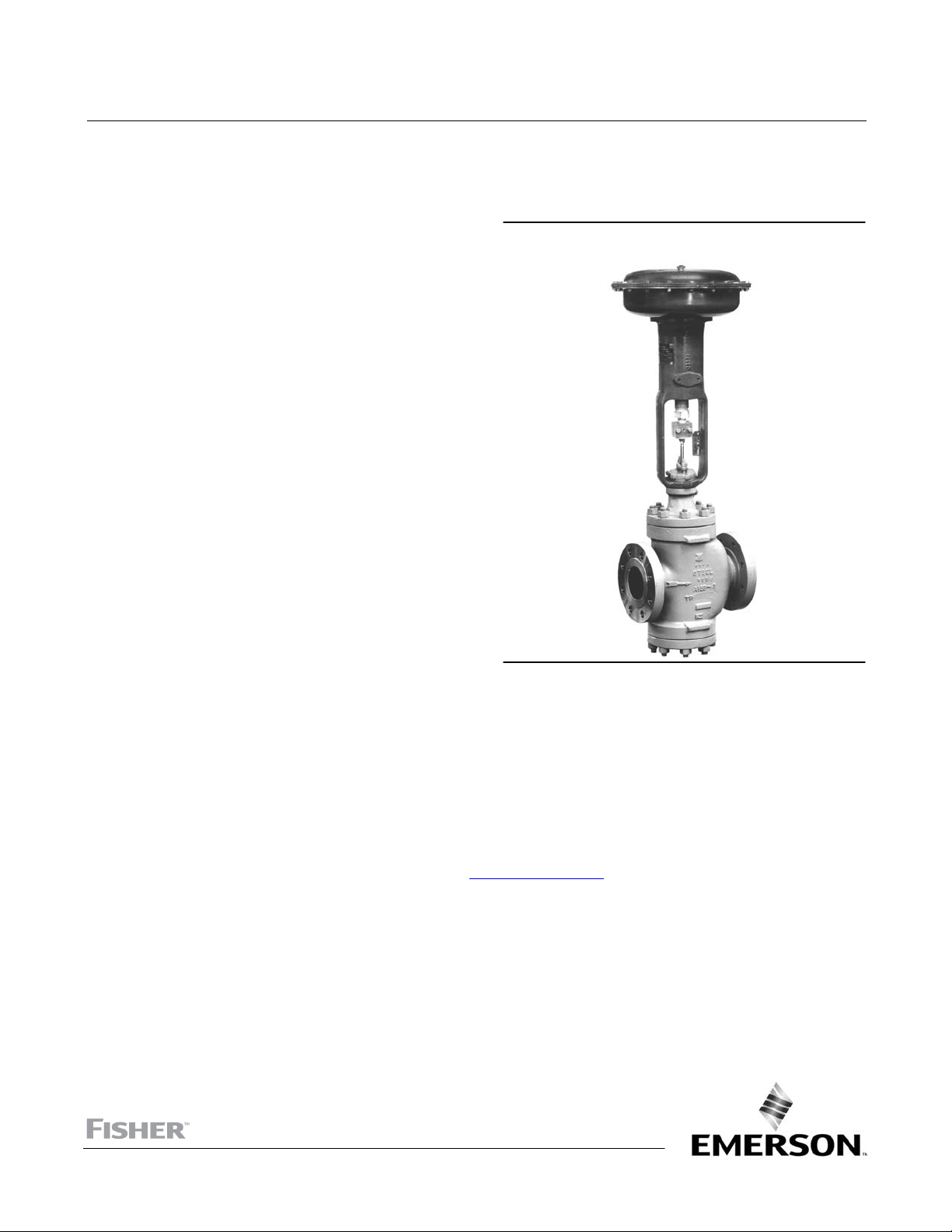
Figure 1. Fisher HS Control Valve with
Diaphragm Actuator
W6003-1
Introduction
Scope of Manual
This instruction manual provides installation, maintenance, and parts information for the NPS 1 through NPS 10 HS
control valves with ANSI CL900 through CL1500 pressure ratings. Refer to separate manuals for instructions on the
actuator and accessories.
Do not install, operate, or maintain a HS control valve without being fully trained and qualified in valve, actuator, and
accessory installation, operation, and maintenance. To avoid personal injury or property damage, it is important to
carefully read, understand, and follow all the contents of this manual, including all safety cautions and warnings. If you
have any questions about these instructions, contact your Emerson sales office
Description
These valves are either single-port or double-port constructions. Direct-acting valves have push-down-to-close action.
If the valve is installed in a horizontal pipe run and the actuator is vertical above the valve, downward motion of the
valve stem will close the valve.
HS valve plugs are, top-and- bottom guided. With top-and-bottom guiding, a bushing in the bottom flange and in the
bonnet guide the valve plug. Maintenance procedures in this manual are valid for either single or double-port valves.
before proceeding.
www.Fisher.com
Page 6

HS Valve
June 2019
Table 1. Specifications
Instruction Manual
D100381X012
End Connection Styles
Buttwelding: Available in ASME B16.25 schedules that
are compatible with ASME B16.34
pressure/temperature ratings
Flanged: CL900 or CL1500 ring-type joint (RTJ) or
Flow Characteristics
Equal Percentage: V-Pup
Modified Parabolic: Throttle Plug
Quick Opening: Quick Opening Valve Plug
raised-face (RF) flanges per ASME B16.5
Pressure/Temperature Ratings
(1)
Consistent with CL900 or CL1500
pressure-temperature ratings per ASME B16.34
1. The pressure or temperature limits in this manual and any applicable standard or code limitations should not be exceeded.
Flow Direction
Single Port bodies are flow up
Double Port bodies (see figure 2)
Specifications
Typical specifications for HS control valves are shown in table 1.
Figure 2. Double-Port Fisher HS Valve with Top-and Bottom-Guided Throttle Plug Valve Plug
W0474‐1
Installation
WARNING
Always wear protective gloves, clothing, and eyewear when performing any installation operations to avoid personal
injury.
Personal injury or equipment damage caused by sudden release of pressure may result if the valve assembly is installed
where service conditions could exceed the limits given in table 1 or on the appropriate nameplates. To avoid such injury or
damage, provide a relief valve for over‐pressure protection as required by government or accepted industry codes and
good engineering practices.
Check with your process or safety engineer for any additional measures that must be taken to protect against process
media.
2
Page 7

Instruction Manual
D100381X012
If installing into an existing application, also refer to the WARNING at the beginning of the Maintenance section in this
instruction manual.
HS Valve
June 2019
Before installing the valve, inspect it for shipping damage and be certain the valve cavity and adjacent pipelines are
free of any foreign material that may damage the seating surfaces. If continuous operation is required during
maintenance, install a three-valve bypass around the valve.
HS valves may be installed in any position, but the standard position is with the valve in a horizontal run of pipe with
the actuator above the valve.
When installing the valve, use accepted piping and welding practices. For flanged valves, use a suitable flange gasket
between the valve and the pipeline flanges. Orient the valve so that flow will be in the direction indicated by the flow
arrow.
If the actuator was not attached to the valve before installation, or if valve plug travel has not been adjusted, refer to
the Mounting Actuator and Adjusting Travel section in this manual and the appropriate actuator instruction manual.
Maintenance
Valve parts, such as the packing, valve plug, seat ring, and guiding bushings, are subject to normal wear and must be
inspected and replaced as necessary. Inspection and maintenance frequency depends on the severity of service
conditions. This section includes instructions for disassembly necessary for inspection or replacement of parts. All
maintenance operations may be performed with the valve in the line.
WARNING
D Avoid personal injury or property damage from sudden release of process pressure. Before performing any
maintenance operations:
D Do not remove the actuator from the valve while the valve is still pressurized.
D Always wear protective gloves, clothing, and eyewear when performing any maintenance operations to avoid personal
injury.
D Disconnect any operating lines providing air pressure, electric power, or a control signal to the actuator. Be sure the
actuator cannot suddenly open or close the valve.
D Use bypass valves or completely shut off the process to isolate the valve from process pressure. Relieve process pressure
on both sides of the valve. Drain the process media from both sides of the valve.
D Vent the power actuator loading pressure and relieve any actuator spring precompression.
D Use lock-out procedures to be sure that the above measures stay in effect while you work on the equipment.
D The valve packing box may contain process fluids that are pressurized, even when the valve has been removed from the
pipeline. Process fluids may spray out under pressure when removing the packing hardware or packing rings, or when
loosening the packing box pipe plug.
D Check with your process or safety engineer for any additional measures that must be taken to protect against process
media.
Packing Lubrication
If a lubricator or lubricator/isolating valve (figure 3) is provided for PTFE/composition or other packings that require
lubrication, it will be installed in place of the pipe plug. Use a good quality silicon-base lubricant. Packing used in
oxygen service or in processes with temperatures over 500°F (260°C) should not be lubricated. To operate the
3
Page 8

HS Valve
June 2019
Instruction Manual
D100381X012
lubricator, simply turn the cap screw clockwise to force the lubricant into the packing box. The lubricator/isolating
valve operates the same way except the isolating valve must first be opened and then closed after lubrication is
completed.
Figure 3. Lubricator and Lubricator/Isolating Valve
LUBRICATOR
10A9421-A
AJ5428-D
A0832-2/IL
LUBRICATOR/ISOLATING VALVE
Packing Maintenance
Note
If the valve has ENVIRO‐SEAL live‐loaded packing installed see the Fisher instruction manual entitled ENVIRO‐SEAL Packing System
for Sliding‐Stem Valves (D101642X012
If the valve has HIGH‐SEAL heavy‐duty live‐loaded packing installed, see Fisher instruction manual entitled HIGH‐SEAL Live‐Loaded
Packing System (D101453X012
Installation of graphite ribbon packing requires special care to avoid trapping air between the rings. Start with only one
ring at a time without forcing the top of the packing ring below the bottom of the entrance chamfer of the packing
box. Thus, when a ring is added, the stack should not be pushed into the cavity more than the thickness of the added
ring. Key numbers refer to figure 3 for PTFE V-ring packing and to figure 4 for PTFE/composition packing, unless
otherwise indicated.
For spring-loaded single PTFE V-ring packing, the spring maintains a sealing force on the packing. If leakage is noted
around the packing follower, check to be sure the shoulder on the packing follower is touching the bonnet. If the
shoulder is touching the bonnet, tighten the packing flange nuts until the shoulder is provided for PTFE/composition
or other packings that require lubrication, it will be installed in place of the pipe plug until the shoulder is against the
bonnet. If leakage cannot be stopped in this manner, proceed to the replacing packing procedure.
If there is undesirable packing leakage with other than spring-loaded packing, first try to limit the leakage and
establish a stem seal by tightening the packing flange nuts. If the packing is relatively new and tight on the stem, and if
tightening the packing flange nuts does not stop the leakage, it is possible that the valve stem is worn or nicked so that
a seal cannot be made. The surface finish of a new valve stem is critical for making a good packing seal. If the leakage
comes from the outside diameter of the packing, it is possible that the leakage is caused by nicks or scratches around
the packing box wall. If performing any of the following procedures, inspect the valve stem and packing box wall for
nicks and scratches.
) for packing instructions.
) for packing instructions.
4
Page 9

Instruction Manual
D100381X012
Figure 4. PTFE V-Ring Packing Arrangements for Standard and Radiation Bonnets
UPPER WIPER
(KEY 12)
PACKING FOLLOWER
(KEY 13)
WASHER
(KEY 10)
SPRING
(KEY 8)
FEMALE
ADAPATER
PACKING
RING
MALE
ADAPATER
PACKING SET
(KEY 6)
(2 REQ'D FOR
DOUBLE
ARRANGEMENT)
FEMALE
ADAPATER
PACKING
RING
MALE
ADAPATER
HS Valve
June 2019
UPPER WIPER
(KEY 12)
PACKING FOLLOWER
(KEY 13)
SPACER
(KEY 8)
PACKING BOX RING
(KEY 11)
FOR S31600 OR S17400 SST
METAL PACKING BOX PARTS
12A7637-A
B1429-4*/IL
ASSEMBLY 1
(POSITIVE
PRESSURES)
ASSEMBLY 2
(VACUUM)
3/8 INCH (9.5 MM) STEM
ASSEMBLY 3
(POSITIVE
PRESSURES
& VACUUM)
LOWER
WIPER
SINGLE ARRANGEMENTS
ASSEMBLY 1
(POSITIVE
PRESSURES)
ASSEMBLY 2
(VACUUM)
1/2 INCH (12.7 MM) STEM
ASSEMBLY 3
(POSITIVE
PRESSURES
& VACUUM)
ASSEMBLY 1
(POSITIVE
PRESSURES)
LOWER
WIPER
FOR ALL OTHER
METAL PACKING BOX PARTS
ASSEMBLY 2
(VACUUM)
ASSEMBLY 3
(POSITIVE
PRESSURES
& VACUUM)
3/4 OR 1-1/4 INCH
(19.1. 25.4, OR 31.8 MM) STEM
PACKING BOX RING
(KEY 11)
UPPER WIPER
(KEY 12)
PACKING
FOLLOWER
(KEY 13)
MALE
ADAPATER
PACKING
RING
FEMALE
ADAPATER
LATNERN
RING (KEY 8)
PACKING
BOX RING
(KEY 11)
LOWER
WIPER
B1428-4*/IL
DOUBLE ARRANGEMENTS
5
Page 10

HS Valve
June 2019
Instruction Manual
D100381X012
Adding Packing Rings
This section covers adding packing rings to PTFE V-ring, PTFE/composition, and graphite/ribbon packing as used in
standard and radiation bonnets. PTFE V-ring packing is shown in figure 3, PTFE/composition packing is shown if figure
4, and graphite/ribbon packing is shown in figure 5. When using packing with a lantern ring (key 8, figure 3, 4, or 5), it
is possible to add packing rings above the lantern ring as a temporary measure without removing the actuator from
the valve.
1. Isolate the control valve from the line pressure, release pressure from both sides of the valve, and drain the process
media from both sides of the valve. Use lock-out procedures to be sure that the above measures stay in effect while
you work on the equipment.
2. Remove the packing flange nuts and lift the packing flange and follower away from the valve.
3. Avoid scratching the valve stem or packing box wall as the old packing rings are removed from on top of the lantern
ring. Clean all metal parts to remove particles that would prevent the packing from sealing.
4.
Install packing rings.
If split-ring packing is being added, spread the rings over the stem and slide the rings into the packing box.
Alternate the positions of the splits to avoid creating a leak path.
If solid-ring packing is being added, remove the stem connector and slip the rings over the end of the valve stem.
5. Replace the packing flange and packing follower. Tighten the packing flange nuts only far enough to stop leakage
under operating conditions.
6. If the valve-actuator stem connection was taken apart, reconnect according to the appropriate actuator instruction
manual.
7. Check for leakage around the packing follower when the valve is being put into service. Retighten the packing
flange nuts as required.
Figure 5. Detail of PTFE/Composition Packing Arrangements for Standard and Radiation Bonnets
UPPER WIPER
(KEY 12)
PACKING
FOLLOWER (KEY 13)
PACKING RING
(KEY 7)
LANTERN RING
(KEY 8)
PACKING BOX
RING (KEY 11)
3/8 INCH
(9.5 mm)
STEM
TYPICAL (DOUBLE) ARRANGEMENTS
6
1/2 INCH
(12.7 mm)
STEM
3/4, 1, OR
1‐1/4 INCH
(19.1, 25.4, OR
31.8 mm) STEM
Page 11

Instruction Manual
D100381X012
HS Valve
June 2019
Figure 6. Detail of Graphite Ribbon/Filament Packing for Standard and Radiation Bonnets
PACKING FOLLOWER
(KEY 13)
GRAPHITE RIBBON
PACKING RING
(KEY 7)
GRAPHITE FILAMENT
PACKING RING
(KEY 7)
LANTERN RING
(KEY 8)
PACKING BOX RING
(KEY 11)
3/8 INCH
(9.5 mm) STEM
1/2 INCH
(12.7 mm) STEM
SINGLE ARRANGEMENTS
3/4, 1, OR 1‐1/4 INCH
(19.1, 25.4, OR 31.8 mm) STEM
PACKING FOLLOWER
(KEY 13)
GRAPHITE RIBBON
PACKING RING
(KEY 7)
GRAPHITE FILAMENT
PACKING RING
(KEY 7)
LANTERN RING
(KEY 8)
PACKING BOX RING
(KEY 11)
3/8 INCH
A5864/IL
NOTES:
1
0.004 INCH (0.102 mm) THICK SACRIFICIAL ZINC WASHERS; USE ONLY ONE BELOW EACH GRAPHITE RIBBON RING.
(9.5 mm) STEM
1/2 INCH
(12.7 mm) STEM
DOUBLE ARRANGEMENTS
3/4, 1, OR 1‐1/4 INCH
(19.1, 25.4, OR 31.8 mm) STEM
Replacing Packing
1. Isolate the control valve from the line pressure, release pressure from both sides of the valve body, and drain the
process media from both sides of the valve. If using a power actuator, also shut-off all pressure lines to the power
actuator, release all pressure from the actuator. Use lock-out procedures to be sure that the above measures stay in
effect while you work on the equipment.
2. Disconnect the valve stem from the actuator by unscrewing the cap screws and removing the stem connector.
3. Unscrew the yoke locknut (valves with 3/8, 1/2, or 3/4-inch stems) or eight cap screws and nuts (valves with 1 or
1-1/2-inch stems). Remove the actuator from the valve.
4. To remove the bonnet (key 29), unscrew the bonnet nuts (steel valves); then proceed as follows:
a. For direct-acting valves, remove the bonnet, valve plug, and stem as a unit. Unscrew the packing flange nuts and
remove the packing flange, upper wiper (if one is used) and packing follower. Slide the valve plug and stem out
of the bonnet.
7
Page 12

HS Valve
June 2019
Instruction Manual
D100381X012
5. Carefully push out all the remaining packing parts from the valve side of the bonnet using a rounded rod or
other tool that will not scratch the packing box wall.
6. Clean the packing box and all metal packing box parts.
7. Install a new bonnet gasket on the valve. With the valve plug and stem in the valve, slide the bonnet over the stem
and onto the valve.
Note
The prelubricated stud bolt nuts referred to in step 8 can be identified by a black film coating on the nut threads. The accepted
bolting procedures in step 8 include—but are not limited to—ensuring that bolting threads are clean, and evenly tightening the cap
screws, or the nuts onto the studs, in a crisscross pattern. Repeat the crisscross tightening pattern several times until each cap
screw or nut is tight and the body-to-bonnet seal is made.
8. Lubricate the bonnet bolting with anti-seize lubricant (not necessary if factory prelubricated stud bolt nuts are
used) and install it, using accepted bolting procedures during tightening so that the body-to-bonnet joint will
withstand test pressures and application service conditions. The bolt torques in table 4 may be used as guidelines.
9. Using care to avoid damaging packing on the valve stem thread, install packing and associated parts in the
appropriate sequence. Replace the packing flange and packing flange nuts.
10. Tighten the packing flange nuts as follows:
a. For spring-loaded PTFE V-ring packing, tighten the packing flange nuts until the shoulder on the packing follower
contacts the bonnet.
b. For graphite packing, tighten the packing flange nuts to the maximum recommended torque shown in table
5. Then, loosen the packing flange nuts, and retighten them to the recommended minimum torque shown in
table 5.
c. For other packing types, tighten the packing flange nuts alternately in small equal increments until one of the
nuts reaches the minimum recommended torque shown in table 5. Then, tighten the remaining flange nuts until
the packing flange is level and at a 90-degree angle to the valve stem.
d. For ENVIRO-SEAL or HIGH-SEAL live-loaded packing, refer to the note at the beginning of the Maintenance
section.
11. Mount the actuator and adjust the stem connector per the Mounting Actuator and Adjusting Travel section and the
appropriate actuator instruction manual.
Table 4. Body‐to‐Bonnet Bolt Torque Guidelines
VALVE SIZE,
NPS
NSm LbfSft NSm LbfSft
1 400 90 400 90
1‐1/2 534 120 534 120
2 845 190 845 190
3 1223 275 1223 275
4 1223 275 1223 275
6 2335 525 2335 525
8 4159 935 4159 935
10 4159 935 4159 935
1. Contact your Emerson sales office for torques required for other bolting materials.
2. For bolting field-lubricated using anti-seize lubricant, contact your Emerson sales office for torques required with other lubricants.
(1)
SA‐193‐B7
SA‐193‐B16
BOLT TORQUES
Steel and Stainless Steel Valves with Studs and Nuts
(2)
Strain Hardened
SA‐193‐B8M
8
Page 13

Instruction Manual
D100381X012
Table 5. Recommended Torque for Packing Flange Nuts (Non Live‐loaded Graphite Packing)
STEM
DIAMETER
mm Inches Min Max Min Max
12.7 1/2 CL900 12 18 9 13
12.7 1/2 CL1500 15 22 11 16
19.1 3/4 CL900 27 41 20 30
19.1 3/4 CL1500 34 50 25 37
25.4 1 CL900 42 62 31 46
25.4 1 CL1500 52 77 38 57
31.8 1‐1/4 CL900 56 83 41 61
31.8 1‐1/4 CL1500 68 102 50 75
50.8 2
1. For intermediate class ratings, use the same torque as the next lower standard class.
VALVE BODY
(1)
RATING
CL1500 98 146 72 108
NSm lbfSft
TORQUE
Trim Maintenance
WARNING
HS Valve
June 2019
D Observe the warnings at the start of the Maintenance section.
Replacing Valve Plug, Seat Ring(s), and Guide Bushings
1. Isolate the control valve from the line pressure, release pressure from both sides of the valve body, and drain the
process media from both sides of the valve. If using a power actuator, also shut-off all pressure lines to the power
actuator, release all pressure from the actuator. Use lock-out procedures to be sure that the above measures stay in
effect while you work on the equipment.
2. Disconnect the valve stem from the actuator by unscrewing the cap screws and removing the stem connector.
3. To remove the valve plug, use the appropriate procedure below:
For direct-acting valves:
a. Disconnect all pressure lines from the actuator. Unscrew the yoke locknut (valves with 3/8, 1/2, or 3/4-inch
stems) or eight cap screws and nuts (valves with 1 or 1-1/4 inch stems). Remove the actuator from the valve.
b. Unscrew the bonnet bolts bonnet nuts (steel valves). Remove the bonnet, valve plug , and stem as a unit.
c. Loosen the packing flange nuts and carefully slide the valve plug and stem out of the bonnet.
4. To replace the guide bushings, press them out of the bonnet and bottom flange. If the bushings cannot be removed
in this manner, machine out the old bushings. Press the new bushings into place. Spin or crimp the bushing
retaining lip into place per figure 7.
9
Page 14

HS Valve
June 2019
Figure 7. Bushing Placement
BONNET
OR
LOWER FLANGE
Instruction Manual
D100381X012
DETAIL A
BUSHING
GE99834
DETAIL A
5. Before removing the seat ring(s) check to see if the seat rings have been welded in place. If so, cut away the weld
before proceeding. Apply penetrating oil to the seat ring threads before attempting to remove the ring(s).
The following seat ring removal instructions are presented assuming a seat ring puller, as shown in figure 8, is being
used:
a. Place the proper size seat lug bar across the seat ring so that the bar contacts the seat lugs as shown in figure 8.
b. Insert a drive wrench and place enough spacer rings over the wrench so that the hold-down clamp will rest about
1/4 inch above the valve flange.
Figure 8. Seat Ring Puller
TURNING BAR
DRIVE WRENCH
HOLD DOWN CLAMP
SPACER RINGS
SEAT LUG BAR
AD5222-B
A1615/IL
Slip a hold-down clamp onto the drive wrench and secure the clamp to the valve with two cap screws (or two studs and
hex nuts) from the bonnet. Do not tighten the cap screws or nuts.
10
Page 15

Instruction Manual
D100381X012
HS Valve
June 2019
c. Use the turning bar to unscrew the seat ring. Stuck seat rings may require additional force on the turning bar.
Apply a steady force to the turning bar and hit the other end of the bar with a heavy hammer as hard as possible
to break the ring loose. In addition, a 24- or 36-inch pipe wrench can be used on the drive wrench near the hold
down clamp. Applying penetration oil to the seat ring before attempting to remove it will facilitate the
operation.
d. After the seat ring is loose, alternately unscrew the flange bolts (or hex nuts) on the hold-down clamp and
continue to unscrew the seat ring.
e. Before installing new ring(s), thoroughly clean the threads in the valve port(s). Apply pipe compound to the
threads of the new seat ring(s).
Note
On double-port valves, one of the seat rings is smaller than the other. On direct-acting valves (push-down-to-close action), install
the smaller ring in the valve body port farther from the bonnet before installing the larger ring.
Screw the seat ring(s) into the valve. Use the seat ring puller, to tighten the seat rings in the valve to the torque values
specified in table 6 and 7. Remove all excess pipe compound after tightening. The seat ring can be spot welded in
place to ensure that it does not loosen.
6. Reassemble the valve in the reverse order of the procedure used to disassemble. Use new bonnet and bottom
flange gaskets when reassembling.
7. Mount the actuator and adjust the stem connector per the Mounting Actuator and Adjusting Travel section and the
appropriate actuator instruction manual.
Table 6. HS Single Port Seat Ring Torque Values
VALVE SIZE, NPS TORQUE (ftSlbs)
1 145
1.5 230
2 270
3 470
4 745
6 2635
8 3345
Table 7. HS Double Port Seat Ring Torque Values
VALVE SIZE, NPS TOP SEAT RING TORQUE (ftSlbs) BOTTOM SEAT RING TORQUE (ftSlbs)
1.5 235 195
2 425 315
3 320 300
4 550 510
6 1845 1705
8 6190 4920
10 5800 4605
11
Page 16

HS Valve
June 2019
Instruction Manual
D100381X012
Lapping Metal Seats
A certain amount of leakage should be expected with metal-to-metal seating in any valve body. However, if the
leakage becomes excessive, the condition of the seating surfaces of the valve plug and seat ring(s) can be improved by
lapping. (Deep nicks should be machined out rather than ground out.) Use a good quality lapping compound of a
mixture of 280 to 600-grit. Apply the compound to the bottom of the valve plug.
To ensure correct alignment of the valve plug, bolt the bonnet in place during the lapping process. Removal of the
packing facilitates the lapping. A simple handle can be made from a piece of strap iron locked to the valve plug stem
with nuts. Rotate the handle alternately in each direction to lap the seats.
On double-port valves, the top ring normally grinds faster than the bottom ring. Under these conditions, continue to
use lapping compound on the bottom ring, but use only a polishing compound (rottenstone and oil) on the top ring. If
either of the ports continues to leak, use more lapping compound on the seat ring that is not leaking and polishing
compound on the other ring. This procedure grinds down the seat ring that is not leaking until both seats touch at the
same time. Never leave one seat ring dry while grinding the other.
After lapping, remove the bonnet, clean the seating surfaces, reassemble, and test the valve for shutoff. Repeat the
lapping procedure if leakage is still excessive.
Figure 9. Actuator Mounting (Type 657 Actuator Shown)
CAP SCREWS
STEM CONNECTOR
1
YOKE LOCKNUT
TRAVEL INDICATOR DISK
STEM LOCKNUTS
TRAVEL INDICATOR SCALE
NOTES:
1
YOKE LOCKNUT IS REPLACED BY EIGHT CAP SCREWS AND
NUTS ON 5-INCH YOKE BOSS (1 AND 1-1/4 INCH STEMS).
A1507/IL
12
Page 17

Instruction Manual
D100381X012
HS Valve
June 2019
Mounting Actuator and Adjusting Travel
Direct-Acting Valves
(Push-Down-to-Close)
1. If the actuator and valve have been separated, mount the actuator and secure with the yoke locknut (valves with
3/8, 1/2, or 3/4-inch stems) or eight cap screws and nuts (valves with 1 or 1-1/4 inch stems).
2. Move the valve plug to the closed position.
3. Screw two locknuts all the way onto the valve plug stem thread. Set the travel indicator disk on these nuts with the
concave side of the disk facing the valve. On some larger actuator sizes, a pointer attached to the stem connector is
used instead of the travel indicator disk.
WARNING
To avoid personal injury, keep hands and tools away from the actuator stem when pressuring the actuator.
4. If the actuator stem is not fully extended, pressure the actuator to move the stem to the fully extended position.
Retract the actuator stem approximately 1/8 inch by reducing actuator pressure. (This requires pressuring the
actuator for reverse-acting diaphragm actuators and piston actuators).
5. Clamp the actuator stem to the valve stem with the stem connector. Raise the indicator disk to the stem connector
and tighten in position with the stem locknuts.
6. Cycle the actuator to be sure that full travel is being obtained and that the valve plug seats before the travel stop (if
one is present) is contacted.
CAUTION
Do not use wrenches or other tools directly on the valve plug stem, or damage to the stem surface and subsequent damage
to the valve packing may result. Never rotate the valve plug stem while the valve plug is in contact with the valve seat ring,
or damage to the valve seating surfaces may result. Be certain the plug is off the seat before rotating the stem.
Minor travel adjustments can be made by loosening the stem connector slightly, tightening the locknuts together,
and screwing the stem into or out of the stem connector by using a wrench on the locknuts. If an increase in travel is
desired, the increase must be less than the 1/8 inch the actuator stem was retracted in step 4, or the valve will not shut
off.
7.
After adjustments are complete, tighten the stem connector securely, lock the travel indicator disk against the
connector with the locknuts, and adjust the travel indicator scale to show valve plug position.
8. Final adjustments to establish the starting point of valve travel (zero) and to obtain full travel for the given signal
range (span) can be made to the actuator spring or valve positioner. Refer to the appropriate actuator or valve
positioner instruction manual for instructions.
13
Page 18

HS Valve
June 2019
Instruction Manual
D100381X012
Parts Ordering
Each HS control valve is assigned a serial number, which can be found on the nameplate. Refer to the number when
contacting your Emerson sales office
WARNING
Use only genuine Fisher replacement parts. Components that are not supplied by Emerson Automation Solutions should
not, under any circumstances, be used in any Fisher valve, because they may void your warranty, might adversely affect the
performance of the valve, and could cause personal injury and property damage.
for assistance or when ordering replacement parts.
14
Page 19

Instruction Manual
D100381X012
HS Valve
June 2019
15
Page 20

HS Valve
June 2019
Instruction Manual
D100381X012
Neither Emerson, Emerson Automation Solutions, nor any of their affiliated entities assumes responsibility for the selection, use or maintenance
of any product. Responsibility for proper selection, use, and maintenance of any product remains solely with the purchaser and end user.
Fisher and ENVIRO-SEAL are marks owned by one of the companies in the Emerson Automation Solutions business unit of Emerson Electric Co. Emerson
Automation Solutions, Emerson, and the Emerson logo are trademarks and service marks of Emerson Electric Co. All other marks are the property of their
respective owners.
The contents of this publication are presented for informational purposes only, and while every effort has been made to ensure their accuracy, they are not
to be construed as warranties or guarantees, express or implied, regarding the products or services described herein or their use or applicability. All sales are
governed by our terms and conditions, which are available upon request. We reserve the right to modify or improve the designs or specifications of such
products at any time without notice.
Emerson Automation Solutions
Marshalltown, Iowa 50158 USA
Sorocaba, 18087 Brazil
Cernay 68700 France
Dubai, United Arab Emirates
Singapore 128461 Singapore
www.Fisher.com
16
E 1975, 2019 Fisher Controls International LLC. All rights reserved.
 Loading...