

DVC6200 Digital Valve Controller on 585C and 471-16, Size 60-130 with 4 to 8 Inch Travel (Linear Roller Cam)
Fisher DVC6200 Digital Valve Controller on 585C and 471-16, Size 60-130 with 4 to 8 Inch Travel (Linear Roller Cam) Mounting Instructions
Page 1

Mounting Instructions
D103462X012
June 2010
DVC6200 Digital Valve Controller on
585C and 471-16, Size 60-130 with
4 to 8 Inch Travel (Linear Roller Cam)
Use these instructions to mount a Fisher® FIELDVUETM
DVC6200 digital valve controller on Fisher 585C and
471-16 Size 60-130 actuators, with 4 to 8 inch travel.
Avoid personal injury or property damage
from sudden release of process pressure
or bursting of parts. Before performing any
installation o
x Always wear protective clothing, gloves,
and eyewear.
x Do not remove the actuator from the
valve while the valve is still pressurized.
x Disconnect any operating lines
providing air pressure, electric power, or a
control signal to the actuator. Be sure the
actuator cannot suddenly open or close the
control valve.
x Use bypass valves or completely shut
off the process to isolate the control valve
from process pressure. Relieve process
pressure from both sides of the control
valve.
x Vent the pneumatic actuator loading
pressure and relieve any actuator spring
precompression.
x Use lock-out procedures to be sure that
the above measures stay in effect while you
work on the equipment.
x Check with your process or safety
engineer for any additional measures that
must be taken to protect against process
media.
Refer to figure 3 and the parts list for mounting parts
identification. Refer to the DVC6200 digital valve
controller instruction manual for digital valve controller
parts identification. Refer to the appropriate actuator
instruction manual for actuator installation, operation,
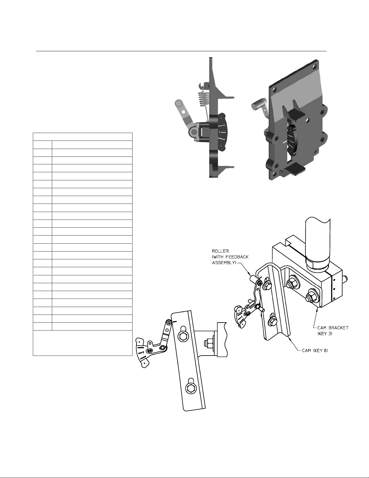
maintenance, and parts identification. Figure 1 shows
the arced feedback assembly.
1. Isolate the control valve from the process line
pressure and release pressure from both sides of the
valve body. Shut off all pressure lines to the actuator,
releasing all pressure from actuator.
Use lock-out procedures to be sure that the above
measures stay in effect while you work on the equipment.
2. During the attachment of cam bracket (key 3) to the
valve stem connector it will be necessary to remove the
stem connector cap screws. Consult the appropriate
______________________________________________________________________________________________________
www.Fisher.com
perations:
actuator instruction manual for proper actuator
disassembly and reassembly.
3. Attach the cam bracket (key 3) to the stem connector
using two stud bolts (key 1), two plain washers (key 4)
and four hex nuts (key 6). If provided, use spacers (key
2) and/or two lock washers (key 5) to attach the cam
bracket to stem connector, as shown in figure 4.
4. Attach the cam (key 8) to the cam bracket using plain
washers (key 9), hex head screws (key 10), lock
washers (key 11) and hex nuts (key 12). If provided, use
spacers (key 7) in between cam and cam bracket, as
shown in figure 4. Ensure that the cam is oriented as per
the mounting assembly drawing.
5. Attach mounting plate(bracket) (key 13) to actuator
yoke top mounting face using two lock washers (key 14)
and hex head screws (key 15). If provided, use the
spacer (key 16) in between mounting plate and yoke
mounting face, as shown in figure 4. Similarly, attach the
mounting plate to bottom yoke mounting by using a
spacer (key 17), stud (key 18), plain washer (key 19),
lock washer (key 14) and hex nut (key 20).
6. Attach the digital valve controller to the arced
feedback assembly (key 21) using the four metric hex
socket cap screws (key 22).
7. Attach the arced feedback assembly along with the
digital valve controller to the mounting plate (bracket)
using the four imperial hex socket cap screws (key 23)
as shown in figure 3. Ensure that the roller of arced
feedback assembly is centered and resting on the cam
surface as shown in figure 2.
8. Ensure that the cam is positioned so that when the
actuator stem is fully extended the roller lines up with the
mark on the cam.
9. Make pneumatic and electrical connections to the
digital valve controller as described in the digital valve
controller instruction manual.
10. It may be necessary to fine tune the placement of the
cam so that the digital valve controllers receives the
proper feedback by lining up as shown in figure 2.
11. Setup and calibrate the digital valve controller as
described in instruction manual or quick start guide.
For additional information concerning mounting, setup,
calibration, and maintenance of the DVC6200 digital
valve controller, refer to the appropriate instruction
manual.
Page 2
DVC6200 Digital Valve Controller on
585C and 471-16, Size 60-130 with
4 to 8 Inch Travel (Linear Roller Cam)
Note
Neither Emerson, Emerson Process
Management, nor any of their affiliated
entities assumes responsibility for the
selection, use or maintenance of any product.
Responsibility for the selection, use and
maintenance of any product remains with the
purchaser and end user.
PARTS LIST
KEY DESCRIPTION
1 STUD BOLTS
2 SPACER
3 CAM BRACKET
4 PLAIN WASHER
5 LOCK WASHER
6 HEX NUT
7 SPACER
8 CAM
9 PLAIN WASHER
10 HEX HD SCREWS
11 LOCK WASHER
12 HEX NUT
13 MOUNTING PLATE (BRACKET)
14 LOCK WASHER
15 HEX HD SCREWS
16 SPACER
17 SPACER
18 STUD, CONT THD
19 PLAIN WASHER
HEX NUT
20
21 ARCED FEEDBACK ASSEMBLY
22 SOCKET SCREWS (METRIC)1
23 SOCKET SCREWS (IMPERIAL)2
1. METRIC SOCKET SCREWS HAVE A SLIGHTLY
LARGER HEAD THAN THE IMPERIAL SOCKET SCREWS.
2. THE IMPERIAL SOCKET SCREWS CAN BE IDENTIFIED
BY THE COARSER THREADS.
GE42132
Figure 2. Installing Cam and Roller Feedback Assembly
Mounting Instructions
D103462X012
June 2010
Figure 1. Linear Roller Feedback
Page 3

DVC6200 Digital Valve Controller on
Mounting Instructions
D103462X012
June 2010
NOTE: REFER TO MOUNTING ASSEMBLY DRAWING FOR THE SIZE OF PARTS AND QUANTITY USED
Figure 3. Mounting Parts Identification(refer to the Parts List on page 2)
585C and 471-16, Size 60-130 with
4 to 8 Inch Travel (Linear Roller Cam)
Page 4

DVC6200 Digital Valve Controller on
)
(
_
585C and 471-16, Size 60-130 with
4 to 8 Inch Travel (Linear Roller Cam)
Mounting Instructions
D103462X012
June 2010
Figure 4. Mounting Parts Identification(with Spacer
Fisher and FIELDVUE are marks owned by one of the companies in the Emerson Process Management business division of Emerson Electric Co.
Emerson Process Management, Emerson, and the Emerson logo are trademarks and service marks of Emerson Electric Co. All other marks are the
property of their respective owners.
The contents of this publication are presented for informational purposes only, and while every effort has been made to ensure their accuracy, they are
not to be construed as warranties or guarantees, express or implied, regarding the products or services described herein or their use or applicability. All
sales are governed by our terms and conditions, which are available upon request. We reserve the right to modify or improve the designs or
specifications of such products at any time without notice. Neither Emerson, Emerson Process Management, nor any of their affiliated entities assume
responsibility for the selection, Neither Emerson, Emerson Process Management, nor any of their affiliated entities assumes responsibility for the
selection, use, or maintenance of any product, Responsibility for the selection, use, and maintenance of any product remains solely with the purchaser
and end user.
Emerson Process Management
Marshalltown, Iowa 50158 USA
Sorocaba, 18087 Brazil
Chatham, Kent ME4 4QZ UK
Dubai, United Arab Emirates
Singapore 128461 Singapore
www.Fisher.com
___________________________________________________________________________________________________
© Fisher Controls International LLC 2010; All Right Reserved
refer to the Parts List on page 2)
 Loading...