

Fisher DVC6200 Digital Valve Controller on 1061 Size 80-100 Actuator (Window Mount) Mounting Instructions
Page 1

(
)
_
DVC6200 Digital Valve Controller
ounting Instructions
D103452X012
May 2010
Use these instructions to mount a Fisher® FIELDVUE™
DVC6200 digital valve
80-100 actuator.
Avoid personal injury or property damage from
sudden release of process pressure or bursting of
parts. Before performing any installation
operations:
Always wear protective clothing, gloves, and
eyewear.
Do not remove the actuator from the valve while
the valve is still pressurized.
Disconnect any operating lines providing air
pressure, electric power, or a control signal to
the actuator. Be sure the actuator cannot
suddenly open or close the control valve.
Use bypass valves or completely shut off the
process to isolate the control valve from
process pressure. Relieve process pressure
from both sides of the control valve.
Vent the pneumatic actuator loading pressure
and relieve any actuator spring
precompression.
Use lock-out procedures to be sure that the
above measures stay in effect while you work
on the equipment.
Check with your process or safety engineer for
any additional measures that must be taken to
protect against process media.
Refer to figure 3 for mounting parts identification for
1061 Size 80-100. Refer to the DVC6200 digital valve
controller instruction manual for parts identification.
Refer to the appropriate actuator instruction manual for
actuator installation, operation, maintenance, and parts
identification.
1. Isolate the control valve from the process line
pressure and release pressure from both sides of the
valve body. Shut off all pressure lines to the actuator,
releasing all pressure from actuator.
Use lock-out procedures to be sure that the above
measures stay in effect while you work on the
equipment.
_____________________________________________________________________________________________________
wMww.Fisher.com
controller on Fisher 1061, size
on 1061 Size 80-100 Actuator
Window Mount
2. Remove the cover plate screws and cover plate from
the actuator, if present.
3. Install the cam (key 1) on to the lever of the actuator. It
is necessary for use of arced feedback mechanism.
Consult with the appropriate actuator instruction manual
for proper actuator disassembly and reassembly.
4. Attach the cam (key 1) to the lever arm of the actuator
using hex head cap screws (key 2).
Ensure that th
5. Detach the roller assembly from the arced feedback
arm.
6. Refer to figure 2, attach the follower arm extension
(key 3) to the arc feedback arm using hex head cap
screws (key 4), lock spring washers (key 5) and hex nuts
(key 6).
7. Attach the roller assembly to the follower arm
extension (key 3) as shown in figure 2.
8. Attach the digital valve controller to the arced feedback
assembly (key 7) as per the actuator requirement using
hex socket cap screws (key 8).
9. Attach the arced feedback assembly (key 3), along with
the digital valve controller to the yoke of actuator using
hex socket cap screws (key 9) as shown in figure 3.
10. Ensure that the roller of arced feedback assembly is
centered and resting on the cam surface.
11. Make pneumatic and electrical connections to the
digital valve controller as described in the digital valve
controller instruction manual.
12. It may be necessary to fine tune the placement of the
cam so that the digital valve controller receives the proper
feedback.
13. Setup and calibrate the digital valve controller as
described in the digital valve controller instruction manual
or quick start guide.
For additional information concerning mounting, setup,
calibration, and maintenance of the DVC6200 digital
valve controller, refer to the appropriate instruction
manual.
e cam is oriented as show
n in figure 3.
Page 2
DVC6200 Digital Valve Controller
(
)
y
y
on 1061 Size 80-100 Actuator
Window Mount
Note
Neither Emerson, Emerson Process Management,
nor any of their affiliated entities assumes
responsibility for the selection, use or maintenance
of any product. Responsibility for the selection, use
and maintenance of any product remains with the
purchaser and end user.
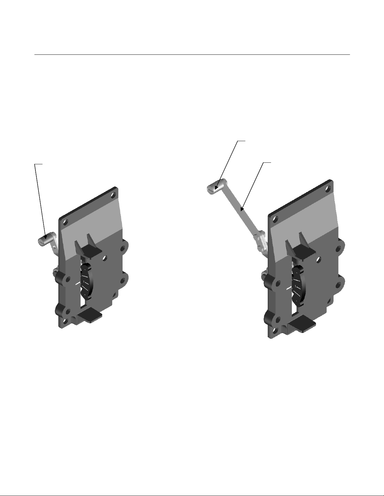
Roller Assembl
Mounting Instructions
Roller Assembl
Follower Arm Extension
D103452X012
May 2010
GE42132
Figure 1. Arced Feedback Assembly
for 1061 Size 80-100
Figure 2. Arced Feedback Assem
Follower Arm Extension and Roller Assembly
bly with
Page 3

DVC6200 Digital Valve Controller
(
)
GG07069
Mounting Instructions
D103452X012
May 2010
DVC6200 Mounting Kit on 1061 Size 80-100 Actuator
PARTS LIST
KEY QTY DESCRIPTION
1 1 CAM
2 2 1/4”-20UNCX0.50” HEX HD SCREWS
3 1 FOLLOWER ARM EXTENSION
4 2 10-24UNCX0.50” HEX HD SCREWS
5 2 NO.10 SIZE LOCK SPRING WASHERS
6 2 NO.10 SIZE HEX NUTS
7 1 ARCED FEEDBACK ASSEMBLY
* 8 4 M8X1.25X16 SOCKET SCREWS
9 4 5/16-18X0.62 SOCKET SCREWS
*NOTE:
The DVC6200 uses 4 M8 socket screws (key 8) for mounting onto arced feedback assembly.
on 1061 Size 80-100 Actuator
Window Mount
1061 Size 80-100 Actuator with DVC6200 Digital Valve Controller
Figure 3. Mounting Parts Identification
Page 4

DVC6200 Digital Valve Controller
(
)
_
on 1061 Size 80-100 Actuator
Window Mount
Mounting Instructions
D103452X012
May 2010
Fisher and FIELDVUE are marks owned by one of the companies in the Emerson Process Management business division of Emerson Electric Co.
Emerson Process Management, Emerson, and the Emerson logo are trademarks and service marks of Emerson Electric Co. All other marks are the
property of their respective owners.
The contents of this publication are presen ted for info rmational pur poses only , and while ev ery effort has been ma de to ensur e their accur acy, they are not
to be construed as warranties or guarante es, expre ss or implied, rega rding the prod ucts or serv ices descri bed herein or the ir use or applicabil ity. All sa les
are governed by our terms and conditions, which are available upon request. We reserve the rig ht to modify or improve the designs or specifications of
such products at any time without notice. Neither E merson, Emer son Proce ss Management , nor any of th eir affiliated e ntities ass ume responsibi lity for the
selection, Neither Emerson, Emerson Process Management, nor any of their affiliated entities assumes responsibility for the selection, use, or
maintenance of any product, Responsibility for the selection, use, and maintenance of any product remains solely with the purchaser and end us er.
Emerson Process Management
Marshalltown, Iowa 50158 USA
Sorocaba, 18087 Brazil
Chatham, Kent ME4 4QZ UK
Dubai, United Arab Emirates
Singapore 128461 Singapore
www.Fisher.com
___________________________________________________________________________________________________
© Fisher Controls International LLC 2010; All Right Reserved
 Loading...