

Page 1

Instruction Manual
D103678X012
Types BLE and BLX
July 2018
Types BLE and BLX Throttle Valves
SUMMARY
Introduction . . . . . . . . . . . . . . . . . . . . . . . . . . . . . . . . 1
Characteristics . . . . . . . . . . . . . . . . . . . . . . . . . . . . . 2
Labelling . . . . . . . . . . . . . . . . . . . . . . . . . . . . . . . . . . 2
Dimensions and Weights . . . . . . . . . . . . . . . . . . . . . 3
Operation . . . . . . . . . . . . . . . . . . . . . . . . . . . . . . . . 4
Installation . . . . . . . . . . . . . . . . . . . . . . . . . . . . . . . . . 4
Commissioning . . . . . . . . . . . . . . . . . . . . . . . . . . . . . 5
Maintenance . . . . . . . . . . . . . . . . . . . . . . . . . . . . . . . 6
Spare Parts . . . . . . . . . . . . . . . . . . . . . . . . . . . . . . . . 10
WARNING
!
Failure to follow these instructions or to
properly install and maintain this equipment
could result in an explosion and/or re
causing property damage and personal
injury or death.
Fisher™ throttle valve device must
be installed, operated and maintained
in accordance with federal, state and
local codes, rules and regulations and
Emerson Process Management Regulator
Technologies, Inc. (Emerson) instructions.
If the throttle valve vents gas or a leak
develops in the system, service to the unit
may be required. Failure to correct trouble
could result in a hazardous condition.
Call a gas service person to service the
unit. Only a qualied person must install or
service the device.
INTRODUCTION
Scope of the Manual
This manual provides installation, startup, maintenance and
parts ordering information for the Types BLE and BLX
throttle valves.
Figure 1. Type BLE-BLX Throttle Valve
The Type BLX is equipped with an integral slam-shut valve
Type OS2 used to cut off pressure ow in the case of
outlet overpressure.
The Type BLE version consists of:
• A body (Type E body) with removable orice, closed with
a cap also serving as a valve guide.
• A balanced valve plug, opened by uid ow,
linear characteristic.
• A valve plug/orice nitrile disc plug, removable and
tight shutoff.
• A valve plug guide with plastic rings and manual handwheel.
• The button serves as an opening indicator.
The Type BLX version, equipped with slam-shut Type OSE
with release relay Type OS2:
• A body (Type X body) including an inferior opening for
lodging the slam-shut.
The slam-shut includes:
• A valve plug/orice assembly with connecting part.
• A release relay Type OS2 including a mechanism box
(BM and a safety manometric box (BMS).
Product Description
The Type BLE throttle valve functions as a bypass on
transmission pressure reducing stations up to 100 bar.
The Types BLE and BLX are in conformity with the
Pressure Equipment Directive PED 2014/68/UE
and are classied in Category IV.
Page 2
PS
18.65 100 16 25 40
Security Class
Types BLE and BLX
CHARACTERISTICS
Table 1. Types BLE and BLX Trottle Valve Characteristics
OPERATING PRESSURE
Body PS 100 bar max
Associated BMS* according to size PSD 10 to 100 bar
Maximum inlet pressure Pumax 100 bar
Type DS Differential strength**
OPERATING TEMPERATURE TS -30 / +71 °C
Body Size DN 25, 50, 80, 100
THROTTLE VALVE
Inlet Pressure Pu 100 bar max
Maximum Differential ∆P max 100 bar
FLUID
Groups 1 and 2 according to PED 2014/68/EU, gas 1 sts and 2nd family according to EN437or other gases (compressed air, nitrogen).
The gas must be non corrosive, clean (ltration on inlet size necessary) and dry.
* BMS: Safety Manometric Box
** Differential strength (according to BMS choice)
SLAM SHUT (TYPE BLX ONLY)
European EN Standard EN 14382
Operation Class A or B (see Figure 2)
Response Time ta < 1 s
Diaphragm
Accuracy
Set Pressure Range Wdu - Wdo 0.010 / 100 bar
Rearming Manual after rectication of fault
Travel Indicator On mechanism box
Bellows
Piston 5
AG
Table 2. Flow Coefcients
DN 25 50 80 100
Qf 230 970 2150 3367
Cg 450 1880 4170 6500
C1 35
Materials
Body Steel
Bonnet Steel
Screw holder Bronze
Orice Stainless steel
Valve plug Steel
Disc plug Nitrile
Connections
Inlet / Outlet Class 600B (ANSI 600 RF)
Class 300B (ANSI 300 RF)
Class 150B (ANSI 150 RF)
Other connections available
(contact factory)
PN 16 B, 25 B, 40 B
2.5
B69a
B69b
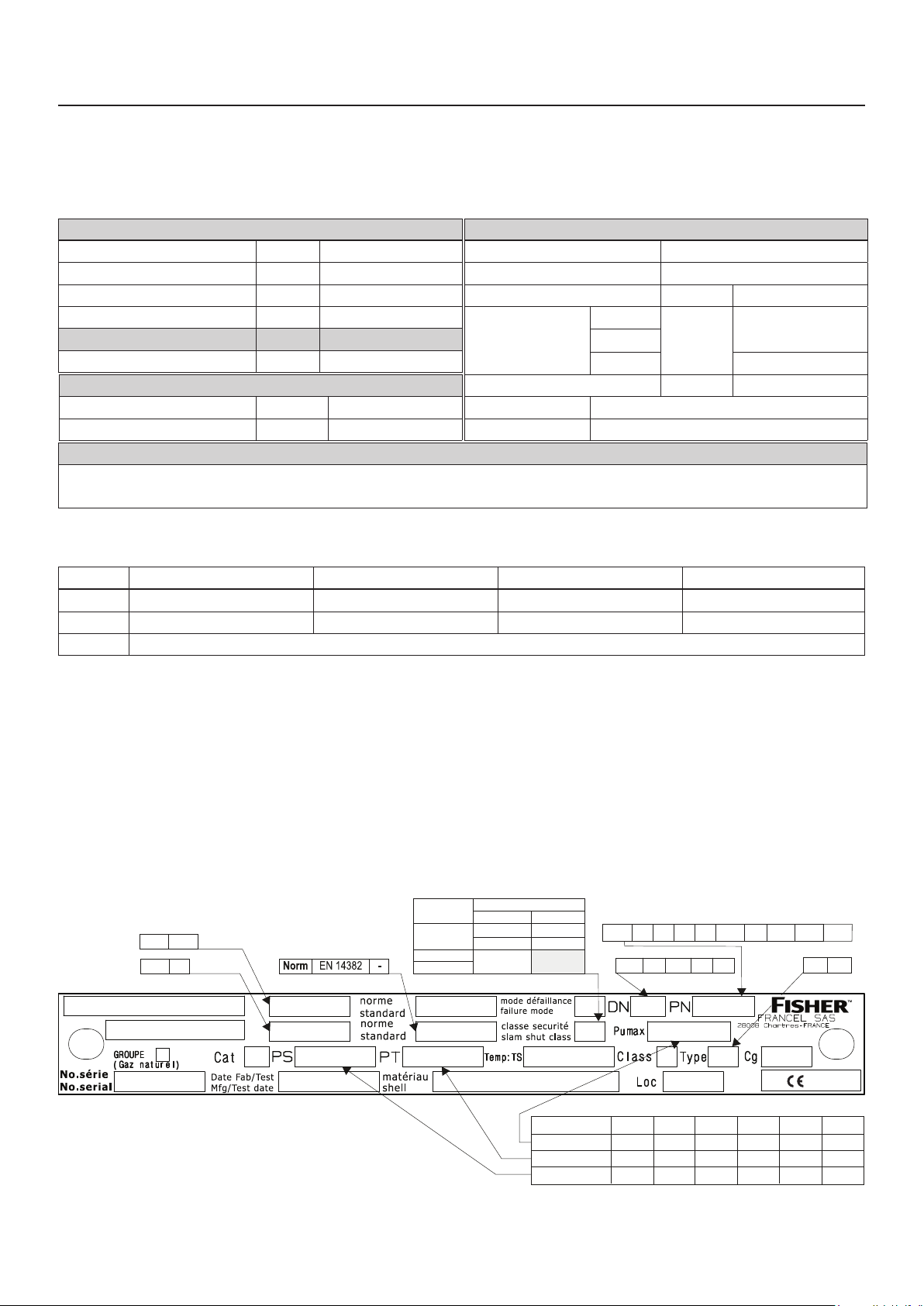
LABELLING
BLE
OS2
VANNE/VALVE
SECURITE/SLAM-SHUT
2
BMS setting
BLX
-
1
IV
DD MM YEAR
bar
Max only
Min only
Max-Min
- -
AB
BMS 027/017 BMS 162
BMS 236/315 BMS 071
All BMS
types
-30/+71 °C
A352LCC+A350LF2
Rating
16B
25B 40B
DN 25 50 80
150 150B 300 300B 600B
100
bar
-
600J
IS
0062
DS
150 300 600 16 25 40Rating
Pumax 18.650 100 16 25 40
PT
32 79 158 26 40 63
Figure 2. Label for Types BLE and BLX Trottle Valve
Page 3
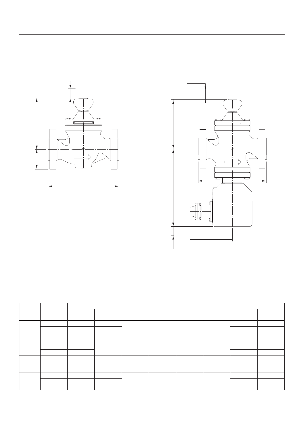
DIMENSIONS AND WEIGHTS
B
A
C
Removal
Types BLE and BLX
B73a
Removal
C
B
A
C
B
Removal
A
DN CLASS
150 185 54
25
50
80
100
300 197
600 210 14 22
150 254 76
300 267
600 287 26.5 40
150 298 95
300 318
600 337 51 65
150 352
300 368
600 394 96 131
220
Removal
Figure 3. Types BLE and BLX Trottle Valve Dimensions
Table 3. Types BLE and BLX Trottle Valve Dimensions and Weights
DIMENSIONS TYPES BLE (WITHOUT SLAM-SHUT) AND BLX (WITH SLAM-SHUT) WEIGHT (kg)
A
(nish B)
BLE BLX BLE BLX
B C
62
83
105
137
315 183 196 55
330 196 213 75
361 223 241 95
410 267 289 120
Removal BLE BLX
12 20
13 21
22.5 36
24.5 38
43 57
49 63
80 115
92 127
B73b
B74
3
Page 4
Types BLE and BLX
OPERATION
Type BLE or BLX
The Type BLE throttle valve is a balanced plug type, opened
by pressure ow.
The opening control is manually performed by a torque
handwheel (approx. 4 N
(see Table 4).
Tight shutoff is achieved by a nitrile disc plug situated on the
valve plug. The disc plug and orice are easily replaced.
The opening control is progressive to start and then linear.
In closed position, an O-ring situated below the handwheel
protects the control screw for exterior corrosion.
A rotation of 1/8 turn after contact with the valve plug / orice
is sufcient to assure tight shutoff.
Slam-Shut (Type BLX)
The pressure of the zone to be protected (in general the
pipeline, outlet side of the regulator and after the slam-shut)
reacts on the safety manometric box (BMS).
•m). 1 handwheel turn = 2 mm travel
If the pressure rises above the set range, the release relay
releases the valve plug.
Due to the action of the closing spring and the uid (trying to
close), the valve plug closes on the orice.
The gas ow is obstructed until the fault has been corrected
and the mechanism box manually rearmed.
Equal pressure balance on inlet and outlet sides are
necessary to reopen the valve plug.
The mechanism box is rearmed after opening the
internal bypass.
Rearming and balancing are achieved at the same time.
Table 4. Opening Control Measurements
DN NO. OF TURNS TRAVEL
25 4 8
50 7.5 15
80 11.5 23
100 15 30
INSTALLATION
WARNING
!
Personal injury or equipment damage, due
to bursting of pressure-containing parts
may result if this device is overpressured or
is installed where service conditions could
exceed the limits given in the Specication
section and on the appropriate nameplate
or where conditions exceed any rating of
the adjacent piping or piping connections.
To avoid such injury or damage, provide
pressure-relieving or pressure-limiting
devices to prevent service conditions
from exceeding those limits. Also, be sure
the installation is in compliance with all
applicable codes and regulations.
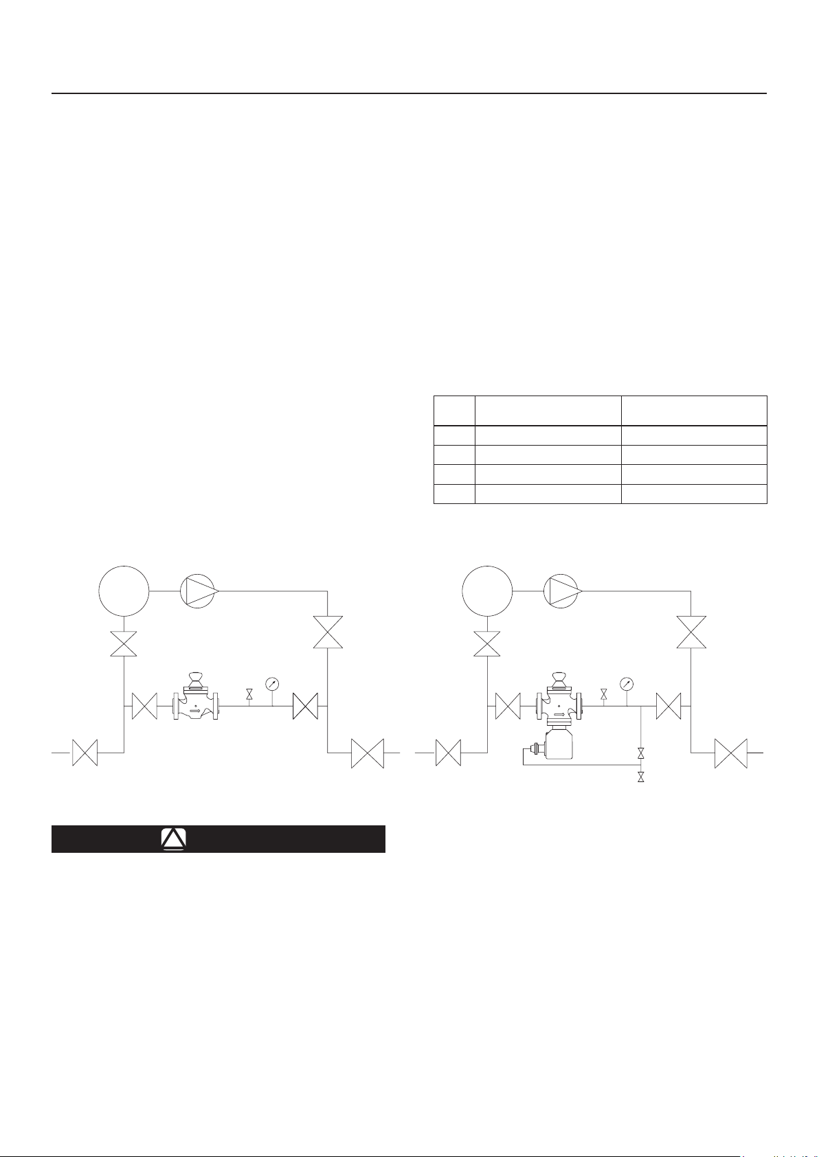
Figure 4. Types BLE and BLX Installation
Additionally, physical damage to the device
can cause personal injury and property
damage due to bursting of pressurecontaining parts. To avoid such injury and
damage, a possible approach could be e.g.
install the device in a safe location.
Respect the direction of the uid ow and the
position of the valve (uid opening the throttle
valve plug).
All interventions on the equipment should
only be performed by qualied and
trained personnel.
Type BLE version, the valve is to be installed on
horizontal or vertical pipeline with the control
handwheel in a top, bottom or lateral position.
B75
4
Page 5

Types BLE and BLX
Type BLX version, the valve is to be installed
on a horizontal pipeline with the control
handwheel in a top or bottom position.
Install according to direction of uid ow
(arrow). Opened by uid ow.
When assembling with adjacent elements
care must be taken not to create pressure
force on the body and the assembling
elements (bolts, O-rings, anges) should be
compatible with the geometry and working
conditions of the equipment.
If the case arises a support must be used to
avoid pressure force on the body (a support
can be installed under the anges).
No modication should be made to the
structure of the equipment (drilling,
grinding, soldering...).
Verify that the inlet side is protected by an
appropriate device(s) to avoid exceeding the
limits of utilization (PS, TS).
Verify that the limits of utilization correspond
to the appropriate operating conditions.
Type BLX version, verify that the safety
manometric box (BMS) and spring correspond
to the appropriate operating conditions on the
outlet side of the throttle valve.
The equipment should not receive any type
of shock, especially the handwheel and
release relay.
Preliminary Verications
Start-up positions
• Inlet and outlet station valves
Open
• Expansion line(s)
Operating
Type BLE (without slam-shut)
• Type BLE inlet valve
Closed
• Type BLE throttle valve
Closed
Positions before commissioning
• Expansion line(s)
Isolated
• Type BLE inlet valve
Open
The equipment is ready for commissioning.
Commissioning
• Type BLE throttle valve
Open slowly observing the manometer outlet
side of the station.
Fire, seismic and lightning are not taken
into consideration in standard regulators.
If required, a special product selection and/
or specic calculations may be supplied
according to specic requirements.
The user should verify or carry out a
protection adapted to the environment.
COMMISSIONING
WARNING
!
All interventions on the equipment should
only be performed by qualied and
trained personnel.
Be sure to slowly introduce pressure into the
system to prevent downstream overpressure
due to potential rapid pressure increase.
Pressure gauges should always be used to
monitor downstream pressure during startup.
The equipment is commissioned.
Type BLX (with slam-shut)
• Type BLX inlet valve
Closed
• Type BLX throttle valve
Closed
• Type BLX slam-shut
Closed
• Impulse line isolation valve
Closed
• Impulse line atmospheric valve
Opened
5
Page 6

Types BLE and BLX
Slam-shut Setpoint Verication
1
3
TRAVEL
STOP
TRIGGERED
POSITION
Figure 5. Slam-Shut Positions
TRAVEL
STOP
STAGE 1 STAGES 2 AND 3
2
TRAVEL
STOP
Using the atmospheric valve, inject a pressure equal to the
pressure required for the regulator.
• 1st release relay stage (BM)
Set (Stage 1)
• Slam-shut valve plug
Open (Stages 2 and 3)
Progressively increase the pressure to reach tripping
Adjust the setting if necessary
(see D103683X012-OS2-IM manual)
Note the setpoint value on the equipment
or mark it on a commissioning document.
Positions Before Commissioning
• Expansion line(s)
Isolated
• Impulse line isolation valve
Open
• Impulse line atmospheric valve
Closed
• Valve plug
Closed
The equipment is ready for commissioning.
Commissioning
• Type BLX inlet valves
Open slowly
• 1st release relay stage
Set (Stage 1)
• Slam-shut internal bypass
Open slowly (Stage 2)
• Slam-shut valve plug
Open (Stage 3)
B76
• Outlet valve
Open slowly
• Type BLX throttle valve
Open slowly observing the manometer outlet side of
the station.
The equipment is commissioned.
It is recommended to seal the release relay.
MAINTENANCE
WARNING
!
To avoid personal injury or property damage
from sudden release of pressure, isolate the
throttle valve from the pressure system and
release all pressure from the main valve before
performing maintenance operations.
Servicing Check
Recommended frequency:
• Types BLE and BLX Once every 2 years for the throttle valve
• Type BLX Twice yearly minimum for the slam-shut
Verication:
• Types BLE and BLX Verication manual opening of the valve
Tight shutoff of the throttle valve plug
• Type BLX Triggering and setpoint verication
Valve plug tight shutoff
Departure positions
• Inlet valve
• Outlet valve
• Servicing valve
• Throttle valve (Types BLE, BLX)
• Slam-shut (Type BLX)
Tight shutoff verication of the throttle valve (Types BLE - BLX)
• Inlet valve
• Servicing valve
• Servicing valve
• Throttle valve
• Throttle valve Observe the evolution of outlet
pressure
Verication of tight shutoff and slam-shut triggering (Type BLX)
• Throttle valve
Open very slowly to slam-shut set
point without exceeding permitted limits
Closed
Closed
Closed
Closed
Open
Open
Open
Closed
Open very slowly and close
when outlet regulator pressure
is achieved
6
Page 7

Types BLE and BLX
Table 5. Troubleshooting for Type BLE Throttle Valve
SYMPTOMS CAUSE ACTIONS
If outlet pressure increases Leak in the throttle valve plug
If outlet pressure is constant Throttle valve plus is tight shutoff
Table 6. Troubleshooting for Type BLX Throttle Valve
SYMPTOMS CAUSE ACTIONS
If the slam-shut valve plug will not close Operation faulty
If the slam shut valve plug closes Operation correct
If the slam-shut valve plug outlet
pressure decreases
If the slam-shut valve plug outlet
pressure is constant
External leak
Purge the outlet side of the
throttle valve
Control the throttle valve plug
Control the throttle orice
or contact after-sales
Control the release relay
Control the slam-shut valve plug
or contact after-sales
Observe the evolution of the outlet pressure
(control tightness)
Locate and seal the leak
or contact after-sales
Observe the evolution of the outlet pressure
(control tightness)
Control the slam-shut valve plug
If the outlet pressure increases Internal leak
Control the orice
Control the internal bypass
or contact after-sales
If the outlet pressure is constant Valve plug is tight shutoff
Table 7. Torque Specications for Screw (key 1) Table 8. Torque Specications for Screws (keys 4 & 15)
(BONNET (KEY 2) CONNECTING PART (KEY 18))
TIGHTENING SCREW KEY 1
DN DIMENSIONS SPANNER (INCHES) TORQUE (N•m)
25 9/16 - 12 x 1 3/4 13/16” 11 0
50 1/2 - 13 x 1 1/2 3/4” 110
80 5/8 - 11 x 1 3/4 15/16” 175
100 3/4 - 10 x 3 1”1/8 200
KEY
4
15 M8 15
DIMENSIONS TORQUE (N•m)
M4 and M5 4
TIGHTENING
M6 6
Table 9. Torque Specications for Bypass (key 19)
TIGHTENING BYPASS (KEY 19)
DN TORQUE (N•m)
25
50
80 20
100 24
14
B78
7
Page 8

Types BLE and BLX
MAINTENANCE
Disassembly of the Throttle Valve
Recommended frequency:
Every 4 to 6 years (or less depending on operating conditions)
CAUTION
In the case of BMS 162 or 071, it is strongly
recommended to check the condition of the
diaphragm once a year.
Verication:
• Condition of O-rings, valve disc plug, lubrication
Replacement:
• O-rings, valve disc plug
Tools:
• 2 at spanners according to DN (see Table 7)
• Six-sided spanners numbers 3, 4, 5, 6, 13, 24
• Box spanner numbers 13, 19
• Remove valve plug (key 6)
• Remove the valve plug support (key 7) (wrench DN 25
and six-sided spanner for DN 50 and 80)
• Unscrew safety nut (key 8) while holding knob (key 9)
• Recover the lower stop part (key 10) (thick washer, cage,
thin washer) and fully unscrew the knob (key 9) to remove
the knob (key 9)/control stem (key 11) assembly
• Remove the valve plug plate (key 13)
• Recover the upper stop part (key 12) (thin washer, cage,
thick washer)
Type BLX (with slam-shut)
As well as above operations
• Unscrew impulse connector IS
• Remove cover (key 14) from BM
• Unscrew xing screws (key 15)
• Remove holding pin
• Remove BM
• Unscrew screw (key 1) from connecting part (key 16)
Precautions Before Disassembly
• Close inlet and outlets valves.
• Valve plug open
Open fully the valve plug by turning the
knob (key 9) until metal/metal contact is made
with the valve plug (key 13) on the bonnet (key 2)
• Bleed off outlet pressure
• Bleed off inlet pressure
Type BLE (without slam-shut)
• Unscrew screws (key 1) from bonnet (key 2)
• Remove bonnet/valve plug assembly
• Remove orice (key 3)
WARNING
!
With knob (key 9) in bottom position
(equipment turned upside down) the orice
(key 3) descends with the bonnet/valve
plug assembly and is just centered by the
columns on the edge of the orice (key 3).
• Remove connecting part (key 16)
• Remove spring (key 17) and valve plug (key 18)
• Unscrew bypass (key 19)
Removing the orice (not recommended) requires a special
extraction tool.
Reassembly
Type BLE (without slam-shut)
• Perform above operations in reverse order (respect
tightening torques)
• Replace O-rings at every disassembly
• Lubricate screws before tightening
• Lightly lubricate O-rings (silicone grease)
• Lubricate the stem (key 11) in the rim (key 20)
(molybdenum graphite grease)
• Precaution must be taken concerning the passage of the
valve plug over the segments
• Unscrew screws (key 4) from pad retainer (key 5)
(only one for DN 25)
8
Page 9

Types BLE and BLX
Type BLX (with slam-shut)
As well as above operations
• Lightly lubricate the O-rings (silicone grease) except for
the valve plug O-ring
• Precaution must be taken concerning the passage of the
valve plug over the segments
11
12
10
6
3
20 9 2
• Lightly lubricate the stem (silicone grease)
• Lubricate the release relay mechanism (yoke and bolt
(molybdenum graphite grease)
• Lubricate the BMS spring (molybdenum graphite grease)
A special tool is required for reassembling a new orice.
1
13
8
7
4
5
19
17
1
14
IS
Figure 6. Types BLE and BLX Maintenance Schematic
18
16
15
B77
9
Page 10

Types BLE and BLX
SPARE PARTS
Release relay Type OS2: see D103683X012-OS2-IM manual
Table 10. Types BLE and BLX Spare Parts
KEY DESCRIPTION QUANTITY
1 O-ring 1
2 O-ring 1 FA400298X12 FA400295X12 FA400297X12 M6020169X12
3 Guide ring 2 M0274090X12 M0272760X12 M0272810X12 ERAA20327A0
4 Anti-extrusion washer 2 M0194530X12 M0194690X12 M0192170X12 ERAA20324A0
5 O-ring 1 FA400524X12 FA400535X12 FA400543X12 ERAA20323A0
6 O-ring 1 FA400104X12 FA400098X12 FA400107X12 M6020171X22
7 O-ring 1 FA400105X12 FA400101X12 FA400108X12 -
8 O-ring 1 FA400106X12 FA400005X12 FA400109X12 ERAA10213A0
9 Valve plug 1 M0280900X12 M0280910X12 M0280920X12 M02990090X12
10 Bypass 1
11 Valve plug O-ring 1 FA400257T12 FA400263T12 FA400258T12 FA400260T12
12 Segment 2 FA401950T12 FA401951T12 FA401952T12 FA401953T12
Packing gland kit
Spare parts kit* FA197801X12 FA197802X12 FA197803X12 FA197987X12
* Including all commissioning spares and O-rings
-
DN 25 DN 50 DN 80 DN 100
BLE BLX BLE BLX BLE BLX BLE BLX
FA400513X12
FA180977T12
-
FA197395X12 FA197395X12 FA197395X12 FA197395X12
-
FA180977T12
-
FA180977T12
FA180977T12
-
B72
10
Page 11

Types BLE and BLX
1
2
3
4
5
6
7
8
9
10
11
12
2
BMS
BM
Type BLXType BLE
Figure 7. Types BLE and BLX Spare Parts
B71
11
Page 12

Types BLE and BLX
Webadmin.Regulators@emerson.com
Fisher.com
Facebook.com/EmersonAutomationSolutions
LinkedIn.com/company/emerson-automation-solutions
Twitter.com/emr_automation
Emerson Automation Solutions
Americas
McKinney, Texas 75070 USA
T +1 800 558 5853
Asia Pacic
Singapore 128461, Singapore
T +65 6770 8337
+1 972 548 3574
Europe
Bologna 40013, Italy
T +39 051 419 0611
Francel SAS, 3 Avenue Victor Hugo,CS 80125, Chartres 28008, France
SIRET 552 068 637 00057 APE 2651B, N° TVA : FR84552068637, RCS Chartres B 552 068 637,
SAS capital 534 400 Euro
Middle East and Africa
Dubai, United Arab Emirates
T +971 4 811 8100
D103678X012 © 2017, 2018 Emerson Process Management Regulator
Technologies, Inc. All rights reserved. 07/18.
The Emerson logo is a trademark and service mark of Emerson
Electric Co. All other marks are the property of their prospective owners.
Fisher™ is a mark owned by Fisher Controls International LLC, a
business of Emerson Automation Solutions.
The contents of this publication are presented for information purposes
only, and while effort has been made to ensure their accuracy, they are
not to be construed as warranties or guarantees, express or implied,
regarding the products or services described herein or their use or
applicability. All sales are governed by our terms and conditions, which
are available on request. We reserve the right to modify or improve the
designs or specications of our products at any time without notice.
Emerson Process Management Regulator Technologies, Inc does not
assume responsibility for the selection, use or maintenance of any
product. Responsibility for proper selection, use and maintenance of any
Emerson Process Management Regulator Technologies, Inc. product
remains solely with the purchaser.
 Loading...