

Page 1
(844)278-03-48, (473)204-51-73, (343)384-55-89, (843)206-01-48, (861)203-40-90, (391)204-63-61,
(495)268-04-70, (831)429-08-12, (846)206-03-16, -(812)309-46-40, (845)249-38-78,
По вопросам продаж и поддержки обращайтесь:
Единый адрес: fhv@nt-rt.ru
Instruction Manual
A41 Valve
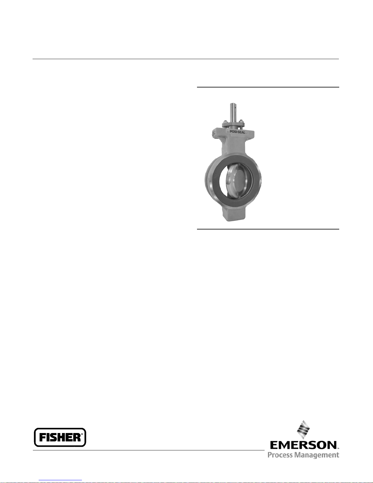
Fisherr A41 High Performance Butterfly Valve
www.fishvalve.nt-rt.ru
Contents
Introduction 1...............................................................
Scope of Manual 1.................................................
Description 1.........................................................
Specifications
Educational Services 2
Installation 5
Valve Orientation 6...............................................
Maintenance 9
Packing Maintenance 12........................................
Seal Ring Maintenance for NPS 3 through 12 13
Seal Ring Maintenance for NPS 2 19.......................
Disc, Drive Shaft and Bearing Maintenance for
NPS 3 through 12
Disc, Drive Shaft and Bearing Maintenance for
NPS 2
Actuator Mounting
Parts Ordering 27
Retrofit Kits for ENVIRO-SEALt Packing 27
Repair Kits for ENVIRO-SEAL Packing 28
Parts List 28
................................................................
.............................................................
.........................................................
...............................................................
...........................................
.....
20.........................................
24.............................................................
26...........................................
............
..................
2....................................................
Figure 1. Fisher A41 Valve
W9269
Introduction
Scope of Manual
This instruction manual includes installation, maintenance, and parts information for Fisher A41 high performance
butterfly valves (figure 1). Refer to separate instruction manuals for information covering the power on-off actuator
and accessories.
Do not install, operate, or maintain A41 valves without being fully trained and qualified in valve, actuator, and
accessory installation, operation, and maintenance. To avoid personal injury or property damage, it is important to
carefully read, understand, and follow all the contents of this manual, including all safety cautions and warnings. If you
have any questions about these instructions, contact your Emerson Process Management sales office before
proceeding.
Description
The A41 high performance butterfly valves have eccentrically mounted discs to reduce wear and reduce torque
requirements. The valve includes filled-PTFE or graphite packing rings that electrically bond the shaft to the valve
body. This valve has a Double D drive shaft end, and soft or metal seal rings for use in a wide variety of applications.
Page 2

Table 1. Specifications
Valve Sizes and End Connection Styles
NPS J 2, J 3, J 4, J 6, J 8, J 10, and J 12 valves
Flow Characteristic
Approximately linear
in wafer or single flanged style (NPS 2 available in
wafer style only)
Flow Direction
See figure 4
Maximum Inlet Pressures
Carbon Steel, Stainless Steel, and CN7M Valves:
Consistent with CL150 and 300 pressure-temperature
ratings per ASME B16.34, unless limited by material
(1)
Disc Rotation
Clockwise to close (when viewing the drive shaft end)
through 90 degrees of disc rotation (see figure 7)
temperature capabilities. NPS 2 is also consistent with
CL600
Maximum Pressure Drops
(1)
Consistent with CL150 and 300 pressure/
temperature ratings per ASME B16.34 except for
PTFE, UHMWPE, and Phoenix III seals that are derated
at some higher pressure/temperatures values. (See
figure 2)
Valve Classification
Face-to-face dimensions of NPS 3 through 12 in
CL150 or 300, and meets API 609 or MSS-SP68
standards for face-to-face dimensions of wafer-style
and single-flange valves
Actuator/Valve Action
With the diaphragm or piston actuators, the valve
action is field-reversible. Refer to information in the
Shutoff Classifications
J PTFE, Reinforced PTFE, and UHMWPE
(2)
Seal: No
visible leakage for this bidirectional seal per MSS
SP-61
J NPS 2 Metal Seal: Bidirectional shutoff. 0.001% of
maximum valve capacity (1/10) of Class IV per
ANSI/FCI 70-2 and IEC 60534-4. Pressure Drop is 740
psig forward and 100 psig reverse
J NOVEX Seal: Unidirectional shutoff is MSS SP-61 in
the preferred flow direction
J Phoenix III Seal: No visible leakage for this
bidirectional seal per MSS SP-61. For optional Phoenix
III Fire-Tested seal, consult your Emerson Process
Management sales office
1. The pressure/temperaturelimits in this manual and any applicable standard or code limitationfor valve should not be exceeded.
2. UHMWPE stands for ultra high molecular weight polyethylene.
Installation section and in figures 6 and 7.
Shaft Diameters
See table 2
Approximate Weights
See table 2
ENVIRO-SEAL Packing
This optional PTFE or graphite packing system
provides excellent sealing, guiding, and transmission
of loading force to control liquid and gas emissions
(see figure 6). See Bulletin 59.3:041 ENVIRO-SEAL
Packing System for Rotary Valves for more
information
2
Page 3
Table 2. Valve Size, Shaft Diameter, and Approximate Weight
VALVE SIZE,
NPS
PRESSURE
CLASS
SHAFT DIAMETER
Wafer-Style Single-Flange
mm Inches kg Pounds kg Pounds
2 150/300/600 12.7 1/2 4.3 9.5 --- ---
3
4
6
8
10
12
150 12.7 1/2 4.5 10 6.4 14
300 15.9 5/8 5.9 13 11 25
150 15.9 5/8 8.6 19 11 24
300 19.1 3/4 10 23 18 39
150 19.1 3/4 13 29 16 35
300 25.4 1 15 33 27 59
150 25.4 1 21 47 27 59
300 31.8 1-1/4 24 53 42 93
150 31.8 1-1/4 34 75 40 88
300 38.1 1-1/2 44 96 78 172
150 38.1 1-1/2 49 107 62 137
300 44.5 1-3/4 64 141 131 288
APPROXIMATE WEIGHT
Table 3. Maximum Allowable Inlet Pressure for M35-1 and CW2M Valve Bodies
(1)
TEMPERATURE M35-1 CW2M
_C Bar
-46 to 38
93
149
204
260
TEMPERATURE CL150 CL300 CL600
15.8
13.8
13.1
12.7
11.7
41.3
36.5
34.1
33.1
32.8
82.7
72.7
68.2
65.8
65.5
20.0
17.9
15.9
13.8
11.7
(2)
CL150 CL300 CL600
51.7
51.7
50.3
48.6
45.9
103.4
103.4
100.3
97.2
91.7
(2)
_F Psig
-50 to 100
200
300
400
500
1. M35-1 and CW2M valvematerial are not included in ASME B16.34 pressure/ temperatureratings. The designations 150 and 300 for this valve material are used only to indicate relative pres
sure/retaining capabilities and are not ASME pressure/ temperature rated classes.
2. CL600 is only available in NPS 2.
230
200
190
185
170
600
530
495
480
475
1200
1055
990
955
950
290
260
230
200
170
750
750
730
705
665
1,500
1,500
1,455
1,410
1,330
3
Page 4
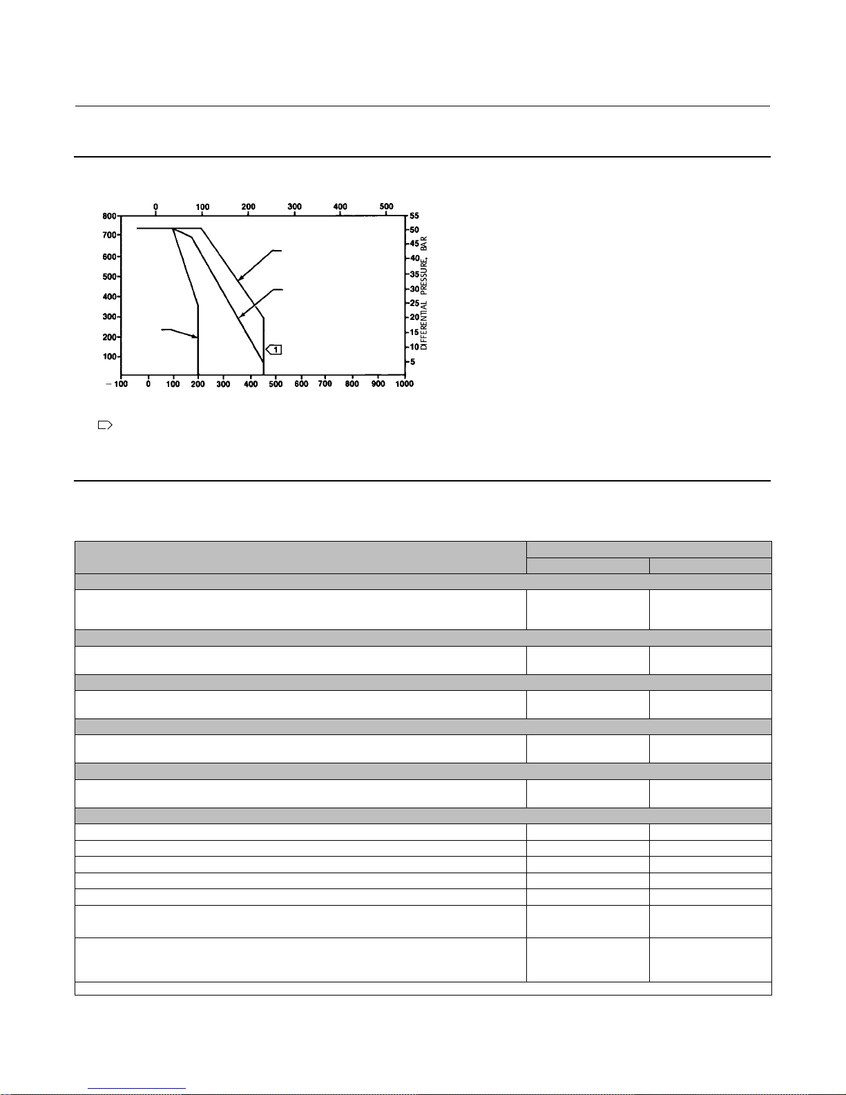
Figure 2. Maximum Pressure/Temperature Ratings
OPERATING TEMPERATURE, _C
PHOENIX III SEAL
WITH PTFE INSERT
PTFE AND REINFORCED
PTFE SEAL
UHMWPE
SEAL
DIFFERENTIAL PRESSURE, PSI
OPERATING TEMPERATURE, _F
NOTE:
1
LIMITATIONS IMPOSED BY THE BACKUP RING USED WITH THIS SEAL.
TO DETERMINE THE EFFECTIVE TEMPERATURE LIMITATION OF THE
APPROPRIATE SEAL/BACKUP RING COMBINATION,REFER TO TABLE 4.
A6306-2
TEMPERATURE LIMITATIONS DO NOT ACCOUNT FOR THE ADDITIONAL
Table 4. Construction Material Temperature Limits
COMPONENTS AND MATERIALS OF CONSTRUCTION
Valve Body Material
Carbon Steel
CF8M
CG8M
Disc Material
S31600
CG8M
Shaft Material
S20910
S17400
Bearing Material
PEEK / PTFE lined
Metal
Packing Material
PTFE V-rings
Graphite rings
Seal Ring
PTFE (Standard) -46 to 232 -50 to 450
Reinforced PTFE Soft Seal Ring -46 to 232 -50 to 450
UHMWPE Soft Seal Ring -18 to 93 0to200
NOVEX Metal Seal Ring -46 to 538 -50 to 1000
NPS 2 Metal Seal ring -46 to 538 -50 to 1000
Phoenix III Metal Seal Ring
Fluorocarbon backup ring -40 to 232 -40 to 450
Phoenix III Fire-Tested
Fluorocarbon backup ring
(Specify metal bearings and graphite packing)
1. For component selection and applicable fire-tested standards and codes, consult your Emerson Process Management sales office.
(1)
Metal Seal Ring
TEMPERATURE LIMITS
_C _F
-29 to 427
-198 to 538
-198 to 538
-198 to 538
-198 to 538
-198 to 538
-62 to 427
-73 to 260
-198 to 538
-46 to 232
-198 to 438
(1) (1)
-20 to 800
-325 to 1000
-325 to 1000
-325 to 1000
-325 to 1000
-325 to 1000
-80 to 800
-100 to 500
-325 to 1000
-50 to 450
-325 to 1000
4
Page 5
Hex Head Cap Screw and Stud Bolt Data
WAFER STYLE SINGLE FLANGE STYLE
VALVE
SIZE,
NPS
(2)
2
3 4 5/8-11 5.75 8 3/4-10 6.5 8 5/8-11 1.875 16 3/4-10 2
4 8 5/8-11 6 8 3/4-10 7 16 5/8-11 2 16 3/4-10 2.25
6 8 3/4-10 6.5 12 3/4-10 7.5 16 3/4-10 2 24 3/4-10 2.5
8 8 3/4-10 7 12 7/8-9 9 16 3/4-10 2.25 24 7/8-9 3
10 12 7/8-9 8 16 1-8 10 24 7/8-9 2.5 32 1-8 3.5
12 12 7/8-9 8.5 16 1-1/8-8 11 24 7/8-9 2.75 32 1-1/8-8 3.75
1. Thread engagement in accordancewith ASME B31.3.
2. The NPS 2 valve is only available in wafer style and is multirated to CL150, 300and 600. The CL600 stud bolts require 8 bolts, have a dia. of 5/8-11, and are 6 inches long.
No. of
Stud
Bolts
4 5/8-11 5 8 5/8-11 5.25 --- --- --- --- --- ---
CL150 CL300 CL150 CL300
Size Dia
Inch &
Thread
A
Dimen-
sion,
Inch
(1)
No. of
Stud
Bolts
Size Dia
Inch &
Thread
A
Dimen-
sion,
Inch
No. of
Cap
Screws
Size Dia
Inch &
Thread
B
Dimen-
sion,
Inch
No. of
Cap
Screws
Size Dia
Inch &
Thread
Figure 3. Cap Screws and Stud Bolts for Installation
B
Dimen-
sion,
Inch
A3887
A
A3886
STUD BOLT CAP SCREW
B
Installation
The valve is normally shipped as part of a valve assembly, with the actuator, handlever, or handwheel mounted on the
valve. If the valve or actuator have been purchased separately, or if the actuator has been removed for maintenance,
mount the actuator on the valve, and adjust actuator travel before inserting the valve body into the line. This is
necessary due to the measurements that must be made during the actuator calibration adjustment process. Refer to
the Actuator Mounting section of this manual and to the separate actuator or handlever instruction manual for
mounting and adjustments before proceeding.
WARNING
Always wear protective gloves, clothing and eyewear when performing any installation or maintenance operations to
avoid personal injury.
To avoid personal injury or property damage resulting from the sudden release of pressure, do not install the valve
assembly where service conditions could exceed the limits given in this manual, the limits on the appropriate nameplates,
or the matching pipe flange rating. Use pressure-relieving devices as required by government or accepted industry codes
and good engineering practices.
Check with your process or safety engineer for any additional measures that must be taken to protect against process
media.
If installing into an existing application, also refer to the WARNING at the beginning of the Maintenance section in this
instruction manual.
5
Page 6
CAUTION
The valve configuration and construction materials were selected to meet particular pressure, temperature, pressure drop,
and controlled fluid conditions specified in the customer's order. Because some body/trim material combinations are
limited in their pressure drop and temperature range capabilities (especially due to differences in thermal expansion rates),
do not apply any other conditions to the valve without first contacting your Emerson Process Management sales office.
1. Install a three-valve bypass around the control valve assembly if continuous operation is necessary during
inspection and maintenance of the valve.
2. Inspect the valve to be certain that it is free of foreign material.
3. Be certain that adjacent pipelines are free of any foreign material, such as pipe scale or welding slag, that could
damage the valve sealing surfaces.
CAUTION
Damage to the disc will occur if any pipe flanges or piping connected to the valve interfere with the disc rotation path. If the
piping flange has a smaller inner diameter than specified for schedule 80 piping, measure carefully to be certain the disc
rotates without interference before putting the valve into operation.
Valve Orientation
When installing the valve, it is highly recommended that the valve drive shaft be horizontal as shown in figure 4.
Valve Direction
The high performance butterfly valve is designed to allow flow in either direction when in the open position. When in
the closed position, high pressure should be applied to a specific side of the disc to provide best performance and
optimal valve life (see list of seal types below). See figure 4.
Table 5. Special Spiral Wound Gasket Dimensions, Inches
Valve Size, NPS Class Gasket Internal Diameter Gasket Outside Diameter
3 150 4.25 5.00 5.375
3 300 4.25 5.00 5.875
4 150 5.25 6.125 6.875
4 300 5.25 6.125 7.125
1. Dimension per API 601and ASME B16.5 Flanges.
Applications with bi-directional seals, such as soft or Phoenix III, under normal operating conditions can (at different
times) experience pressure in both directions; the highest of the two pressures should be exerted on the preferred side
of the disc. If the two pressures are equal, then the one lasting the longest period of time should be applied to the
preferred side.
1. For PTFE, reinforced PTFE, or UHMWPE seal rings: This seal is bidirectional. For best performance, high pressure
should be applied to the front (retaining ring) side of the disc.
2. For metal seal rings:
a. NOVEX seal: The NOVEX seal is uni-directional. High pressure at the closed position MUST be at the back
(waterway side) of the disc.
Centering Outside
Diameter
(1)
6
Page 7
b. Phoenix III Seal: This seal is bidirectional. For best performance, high pressure at the closed position should be
applied to the back (waterway side) of the disc.
c. NPS 2 Seal: The preferred direction of installation is with high pressure at the front (retaining ring side) of the
disc. Reverse shutoff is permissible at lower pressure (see specifications table).
Installing the Valve in the Pipeline
WARNING
The edges of a rotating disc have a shearing effect that may result in personal injury. To help prevent such injury, stay clear
of the disc edges when rotating the disc (figure 4).
CAUTION
Damage to the disc (key 3, figure 12) sealing surfaces may occur if the disc is not closed when the valve is being installed or
removed from the pipeline. If necessary, provide a loading pressure to the actuator temporarily to retain the disc in the
closed position while installing or removing the valve from the pipeline.
1. For Fail-Open Actuators: It will be necessary to provide a temporary loading pressure to the actuator diaphragm to
move the valve disc to the closed position. Observe the above Warning when closing the valve. If a loading pressure
is required, use caution when working with the valve. If the loading pressure is disconnected, the disc will open
rapidly.
2. With the disc in the closed position, install line flange gaskets, and insert the valve between the pipeline flanges.
WARNING
If spiral wound gaskets are to be used with an NPS 3 or 4 CL150 or 300 single flange valve, special spiral wound gaskets
conforming to the dimensions listed in table 5 MUST be used. Improperly sized gaskets may increase the likelihood of 1)
excessive seat leakage, 2) damage due to contact with valve internals, and 3) external leakage; which may result in
personal injury due to a sudden increase or decrease of pressure within -- or release of pressure from -- the pipeline. The
special dimension spiral wound gaskets can be obtained from your local spiral wound gasket vendor.
The remaining single flange valve sizes (NPS 6 through 12) and all wafer style valves (NPS 2 through 12) use the standard
size spiral wound gaskets. Only the single flange valves in the sizes and pressures listed in the table above require special
spiral wound gaskets.
Select the appropriate gaskets for the application. Flat sheet, spiral wound (NPS 6 through 12), or other gasket types
made to ASME 16.5 group or a user's standards can be used for A41 valves depending on the service conditions and
applications.
3. Install the flange studs:
Note
Lubricate line flange studs or bolts before inserting into flanges. If necessary, provide additional support for the control valve
assembly because of its combined weight.
7
Page 8

D Flange Studs: Install two or more line flange studs into the line flanges to help hold the valve in position while
centering the valve. Carefully center the valveontheflangestoensurediscclearance.
D Select and install two pipeline gaskets.
D Flange Cap Screws: If line flange cap screws are used, be certain the cap screw threads engage the tapped holes to a
depth equal to the flange cap screw diameter.
4. Install the remaining line flange bolts to secure the valve in the pipeline. Tighten the bolts in a crisscross pattern to
ensure proper alignment of the valve with the flanges.
Packing A djustment and Shaft Bonding
WARNING
Personal injury could result from packing leakage. Valve packing was tightened before shipment; however, the packing
might require some readjustment to meet specific service conditions.
CAUTION
Excessive tightening of packing will accelerate wear and could produce higher rotating friction loads on the valve stem.
1. For PTFE or graphite packing: Tighten standard packing follower nuts only enough to prevent shaft leakage.
Excessive tightening of packing will accelerate wear and could produce higher rotating friction loads on the valve
stem. If necessary, refer to the Packing Maintenance section.
2. ENVIRO-SEAL Packing Systems will not require this initial re-adjustment. Refer to the separate ENVIRO-SEAL Packing
System for Rotary Valves Instruction Manual (D101643X012) for repair and adjustment procedures.
3. For hazardous atmosphere or oxygen service valves, read the following Warning, and provide the bonding strap
assembly mentioned below if the valve is used in an explosive or hazardous atmosphere.
WARNING
The valve drive shaft is not necessarily grounded to the pipeline when installed. If the process fluid or the atmosphere
around the valve is flammable, personal injury or property damage could result from an explosion caused by a discharge of
static electricity from the valve components.
Standard PTFE packing is composed of a partially conductive carbon-filled PTFE female adaptor with PTFE V-ring packing.
Standard graphite packing is composed of all conductive graphite ribbon packing rings. Alternate shaft-to-valve body
bonding is availablefor hazardous service areas where you feel the the standard packing is not sufficient to bond the shaft
to the valve (see the following steps).
For oxygen service applications it is necessary to provide alternate shaft-to-valve body bonding (see the following steps).
4. Attach the bonding strap assembly (key 131, figure 5) to the shaft with the clamp (key 130, figure 5).
5. Connect the other end of the bonding strap assembly to the valve flange cap screws.
6. For more information, refer to the Packing Maintenance section below.
8
Page 9
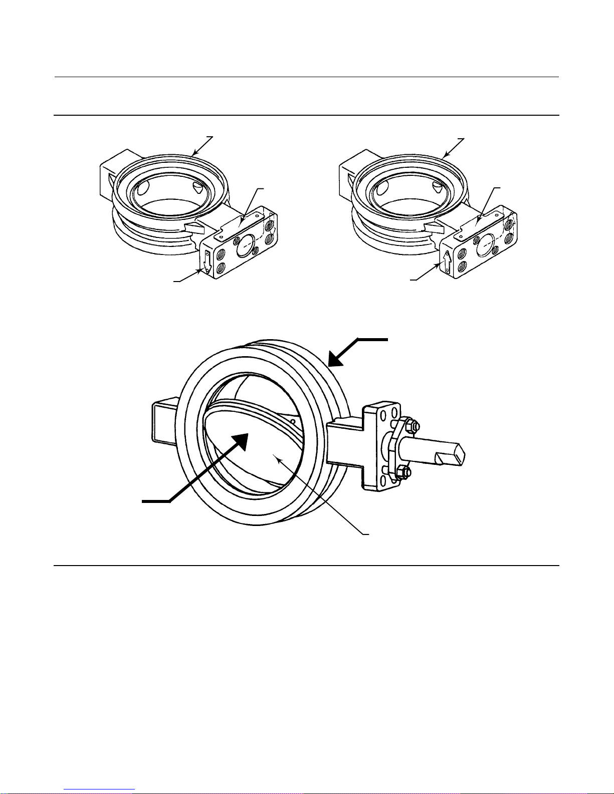
Figure 4. Flow Direction
RETAINER RING SIDE
RETAINER RING SIDE
MFG LABEL
FLOW ARROW
ARROW SHOWS PREFERRED FLOW DIRECTION FOR SOFT SEALS AND NPS 2 METAL SEAL
FORWARD FLOW
MFG LABEL
FLOW ARROW
ARROW SHOWS FLOW DIRECTION FOR NOVEX METAL SEAL, AND PREFERRED
FLOW DIRECTION FOR PHOENIX METAL SEAL
REVERSE FLOW
REVERSE
FLOW
FORWARD
FLOW
NOTES:
1. BY EMERSON PROCESS MANAGEMENT DEFINITION:
D FORWARD FLOW IS INTO THE FACE SIDE OF THE DISC.
D REVERSE FLOW IS INTO THE HUB SIDE OF THE DISC.
75B1181-A
A6881-2
FACE SIDE OF DISC
Maintenance
Valve parts are subject to normal wear and must be inspected and replaced as necessary. The frequency of inspection
and replacement depends upon the severity of service conditions. Instructions are given in this section for replacing
packing, seal ring, disc, shaft, bearings, and other valve parts. Also, instructions are provided for changing valve action,
mounting, and adjusting the actuator. Refer to the actuator instruction manual for additional information for
mounting and adjusting the actuator.
9
Page 10

CAUTION
It is possible to damage the valve if the actuator travel stops are not properly adjusted before stroking the valve.
WARNING
Avoid personal injury or property damage from sudden release of process pressure or bursting of parts. Before performing
any maintenance operations:
D Do not remove the actuator from the valve while the valve is still pressurized.
D Always wear protective gloves, clothing, and eyewear when performing any maintenance operations to avoid personal
injury.
D Disconnect any operating lines providing air pressure, electric power, or a control signal to the actuator. Be sure the
actuator cannot suddenly open or close the valve.
D Use bypass valves or completely shut off the process to isolate the valve from process pressure. Relieve process pressure
from both sides of the valve. Drain the process media from both sides of the valve.
D Vent the pneumatic actuator loading pressure and relieve any actuator spring precompression.
D Use lock-out procedures to be sure that the above measures stay in effect while you work on the equipment.
D The valve packing box may contain process fluids that are pressurized, even when the valve has been removed from the
pipeline. Process fluids may spray out under pressure when removing the packing hardware or packing rings, or when
loosening the packing box pipe.
D Check with your process or safety engineer for any additional measures that must be taken to protect against process
media.
WARNING
The edges of a rotating disc have a shearing effect that may result in personal injury. To help prevent such injury, stay clear
of the disc edges when rotating the disc (key 3).
CAUTION
During the following steps, do not rotate the disc past 90 degrees in the open direction. Rotating the disc past 90 degrees
can damage the seal ring.
Use caution when tightening the packing flange nuts. Overtightened nuts can damage packing box parts.
10
Page 11
Figure 5. Optional Shaft-to-Valve Body Bonding Strap Assembly
VALVE BODY
ACTUATOR
A
37A6528-A
A3143-2
VIEW A-A
A
Stopping Leakage
For PTFE-filled or graphite standard packing arrangements covered in this manual, often leakage from the packing can
be stopped by tightening the packing flange nuts just enough to stop the leak. Use caution when tightening the nuts,
overtightened nuts can damage packing box parts.
D If tightening the packing flange nuts does not stop the leakage, use the following procedures to remove the control
valve assembly from the pipeline, remove the actuator, and to remove and replace the packing parts.
D If the leakage comes from the outside diameter of the packing box, it is possible that the leakage is caused by
scratches on the packing box wall. Carefully inspect the packing box bore and valve drive shaft when the packing is
removed. Use the following steps to remove the actuator, and to remove and replace the packing parts.
Removing the Actuator
WARNING
Refer to the WARNING at the beginning of the Maintenance section in this instruction manual.
1. Isolate the control valve from the line pressure, release pressure from both sides of the valve body, and drain the
process media from both sides of the valve. If using a power actuator, also shut off all pressure lines to the power
actuator, and release all pressure from the actuator. Use lock-out procedures to be sure that the above measures
stay in effect while you work on the equipment.
WARNING
The edges of a rotating disc have a shearing effect that may result in personal injury. To help prevent such injury, stay clear
of the disc edges when rotating the disc (figure 4).
11
Page 12

CAUTION
Damage to the disc (key 3) sealing surfaces may occur if the disc is not closed when the valve is being removed from the
pipeline. For fail open actuators, it may be necessary to apply loading pressure to the actuator to retain the disc in the
closed position while removing the valve from the pipeline.
2. Be sure the disc is in the closed position before attempting to remove the valve from the pipeline or flanges.
For Fail-Open Actuators: It will be necessary to provide a temporary loading pressure to the actuator to move the valve
disc to the closed position. Observe the above Warning when closing the valve. If a loading pressure is required, use
caution when working with the valve. If the loading pressure is disconnected, the disc will open rapidly.
3. With the disc in the closed position, remove line bolting. Remove the valve assembly from the pipeline, and place
the actuator/valve assembly on a flat working surface.
4. Ifagroundingstrapisused(seefigure5),removethehexnuttoreleasetheendofthestrap.Removetheclamp
(key 130) and strap (key 131).
5. Note the orientation of the actuator with respect to the valve body. Also, remove the actuator cover to note the
orientation of the actuator with respect to the valve drive shaft (see figure 7).
When re-assembling the valve assembly, you will need to correctly position the mark on the end of the valve drive
shaft and the valve body, with respect to the actuator drive shaft. Refer to the Actuator Mounting section and figure 7
for the location of the mark on the actuator end of the valve drive shaft. Additional information is provided in the
actuator manual to assist with disassembly, re-assembly, and travel adjustments.
6. Remove the actuator mounting screws (key 14).
7. Remove the actuator from the valve, and remove the valve/actuator coupling.
Packing Maintenance
WARNING
Refer to the WARNING at the beginning of the Maintenance section in this instruction manual.
Standard graphite packing is composed of all conductive packing rings. PTFE-filled packing has a partially conductive
packing ring (such as a carbon-filled PTFE female adaptor) to electrically bond the shaft to the valve body.
If the valve is equipped with the optional ENVIRO-SEAL Packing System, refer to the separate ENVIRO-SEAL Packing
System for Rotary Valves Instruction Manual (D101643X012) for packing maintenance procedures.
When replacing the packing, it is recommended that you remove the control valve assembly from the pipeline.
Valve/actuator travel adjustments must be made with the valve out of the pipeline.
Disassembly
Part locations and key numbers are shown in figures 5 and 11.
1. Remove the packing flange nuts (key 101) and the packing flange (key 114).
2. Remove the old packing rings, using a formed hook.
CAUTION
Carefully use the hook. Avoid scratching the drive shaft or packing box wall. Scratches on valve surfaces can cause leakage.
[Note: the packing box ring (key 107) can remain in place when replacing the packing only.]
12
Page 13

Clean all accessible metal parts and surfaces to remove particles that would prevent the packing from sealing.
Assembly
Inspect the shaft. If it is damaged, it cannot make a good seal with the packing and it must be replaced. If the leakage
comes from the outside diameter of the packing, it is possible that the leakage is caused by nicks or scratches around
the packing box wall. Inspect the packing box wall for nicks and scratches when performing the following procedures.
If the valve is equipped with the ENVIRO-SEAL packing system, refer to the separate ENVIRO-SEAL Packing System for
Rotary Valves Instruction Manual (D101643X012) for assembly.
Note
Except with oxygen service, lightly lubricate new PTFE V-rings with silicone-base lubricant to aid in assembly.
WARNING
Do not lubricate parts when used in oxygen service, or where the lubrication is incompatible with the process media. Any
use of lubricant can lead to the sudden explosion of media due to the oil/oxygen mixture, causing personal injury or
property damage.
1. Install the new packing parts (see figure 6). Install the packing follower and finger tighten the packing flange nuts
onto the studs only enough to stop leakage.
2. If the valve was equipped with a bonding strap assembly (figure 5), re-install the assembly.
3. Refer to the Actuator Mounting section of this manual. If necessary, refer to the separate actuator instruction
manual for adjustment procedures.
4. When the valve is being placed into operation, check around the packing follower for leakage.
For PTFE-filled or graphite standard packing arrangements covered in this manual, often leakage from the packing can
be stopped by tightening the packing flange nuts just enough to stop the leak.
CAUTION
Use caution when tightening the nuts, overtightening nuts can damage packing box parts and result in increaseddrive
shaft friction.
Seal Ring Maintenance for NPS 3 through 12
Perform this procedure if the control valve is not shutting off properly (that is, if it is leaking downstream). It is
recommended, but not required, to remove the actuator for easier handling of the valve during the following
procedures.
Key numbers are shown in figure 12 unless otherwise noted.
13
Page 14

Figure 6. Typical Packing Arrangements
PTFE V-RING PACKING
PACKING
FLANGE
(KEY 102)
REDUNDANT SHAFT
RETENTION
PACKING FOLLOWER
(KEY 102)
PACKING SET
(KEY 105)
PACKING RING
(KEY 105)
PACKING BOX RING
(KEY 107)
STANDARD PACKING
1
GRAPHITE RIBBON PACKING
PACKING FLANGE NUT
(KEY 101)
LUBRICANT
(KEY 113)
SPRING PACK ASSEMBLY
(KEY 103)
ANTI-EXTRUSION RING
(KEY 106)
PACKING SET
(KEY 105)
PACKING
FLANGE
(KEY 102)
REDUNDANT SHAFT
RETENTION
SPRING PACK
ASSEMBLY
(KEY 103)
11B5895-A
10B6817-A
B2435
C0785-2
NOTE:
INCLUDES ZINC WASHERS
1
FOR GRAPHITE RIBBON PACKING ONLY
PACKING SET
(KEY 105)
SPRING COMPRESSED
PACKING FLANGE STUD
(KEY 100)
SHAFT STEP
VALVEBODY(KEY1)
PACKING BOX RING
(KEY 107)
ENVIRO-SEAL PTFE PACKING SYSTEM
PACKING FLANGE
NUT
(KEY 101)
LUBRICANT
(KEY 113)
SPRING COMPRESSED
PACKING FLANGE
STUD (KEY 100)
SHAFT STEP
VALVE BODY (KEY 1)
PACKING BOX
RING (KEY 107)
ENVIRO-SEAL GRAPHITE PACKING SYSTEM
14
Page 15

Figure 7. Disc Rotation Indication
DISC STOP
INDICATES
APPROXIMATE
TO OPEN
DISC POSITION
INDICATES
APPROXIMATE
DISC
POSITION
CAUTION: DO
NOT ROTATE
DISC INTO
THIS SECTOR
ROTATE DISC
IN DIRECTION
SHOWN ONLY
ACTUATOR END
OF SHAFT
2
RETAINER RING
(KEY 2)
DISC IN THE
CLOSED POSITION
Note:
SET ACTUATOR TRAVEL STOPS TO OBTAINAN
EQUAL DISTANCE T DISC SURFACE AS SHOWN.
2
LOCATION OF C MARKINGS FOR NPS 2 ONLY.
A6358
DISC ROTATION INDICATION FOR NPS 2 THROUGH 12
2
Figure 8. Removing the Retainer Ring
FLAT END
PUNCH
DISC IN THE
OPEN POSITION
ROTATE DISC IN
DIRECTION
SHOWN ONLY
A2879-2
DISC ROTATION INDICATION FOR NPS 2
ROTATE DISC IN
EITHER DIRECTION
KNOCK-OUT FLAT
A6359
CAUTION
During any of the following steps, do not rotate the disc past 90 degrees in the open direction. Rotating the disc past 90
degrees can damage the seal ring.
Disassembly
Refer to removing the actuator steps in the Packing Maintenance section. Most maintenance procedures will require
the actuator to be removed.
15
Page 16

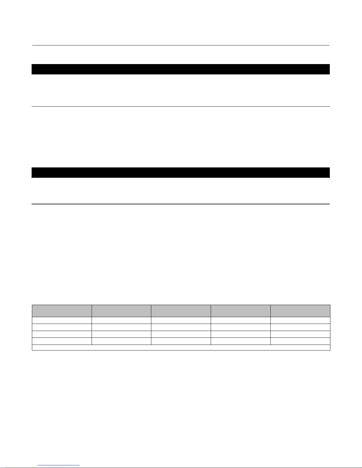
1. Removing the retainer ring (key 2):
For valves with press-fit retainer rings:
D Place the valve on blocks with the seal retainer facing down. (Note: Position blocks so they do not restrict the
retainer ring removal.)
D Rotate the disc to the open position as shown in figure 7.
D On the seal ring side of the retainer ring, locate one of the knock-out points machined on the retainer ring. Using a
hammerandflatendpunchontheknock-outpoint,pop-outtheretainerringfromthevalvebody(seefigure8).
CAUTION
When popping out the retainer ring, be very careful to hit only the knock-out points. Hitting anywhere else can cause
non-repairable damage to the t-slot area.
D For valves with PTFE seal rings, remove the spring (key 5) as it may be necessary to re-install the spring into the new
PTFE seal ring.
D Clean all sealing surfaces and parts before re-assembly. Proceed to step 3 below.
For valves with screwed retainer rings:
D Place the valve on blocks with the seal retainer facing up.
D Remove the retainer ring screws (key 23). If necessary, use two of the retainer screws, in the tapped holes in the
retainer ring (key 2) to jack the retainer ring loose from the valve body surface.
2. Remove the seal ring from the valve body seal ring slot.
D For valves with PTFE seal rings, remove the spring (key 5) as it may be necessary to re-install the spring into the new
PTFE seal ring.
D For valves with metal seals, remove the gasket (key 16) from the valve body surface, and discard it as replacement is
recommended.
3. If it is necessary to replace the disc, drive shaft, and the bearings, refer to the Disc, Drive Shaft, and Bearing
Maintenance section before proceeding with the assembly procedures for the seal ring and retainer. The seal ring
could be damaged if it is in place while removing the disc.
CAUTION
Follow instructions in this manual to avoid damage to the seal ring while either removing or installing the disc.
Assembly
Place the valve on blocks with the seal retainer facing up. If the replacement disc, shaft, and bearings have not been
installed in the valve body, go to the Assembly procedures to install them. Do not install the seal ring without the disc
being in place. The seal ring could be damaged while installing the disc.
16
Page 17

WARNING
Do not lubricate parts when used in oxygen service, or where the lubrication is incompatible with the process media. Any
use of lubricant can lead to the sudden explosion of media due to the oil/oxygen mixture, causing personal injury or
property damage.
CAUTION
Do not rotate the disc past 90 degrees in the open direction. Rotating the disc past 90 degrees can damage the seal ring or
other component parts.
Note
PTFE, NOVEX, and Phoenix Ill seal rings used in other valve types are not interchangeable with seal rings used in the A41 valve. The
A41 seal rings are not interchangeable with seal rings in any other valve type. To order seal rings for this valve, provide the serial
number on the valve.
1. Installing PTFE seal rings:
a. The valve disc should be open while installing the seal ring. If not, rotate the disc to the open position as shown in
figure 7.
b. Hook the spring ends together, insert the spring (see figure 9) into the groove in the seal ring, and work the
spring into the recess in the PTFE seal ring.
c. Install the seal ring (key 4) assembly into the slot in the valve body as shown in figure 9. Refer to installing the
retainer ring steps below.
2. Installing metal seals:
Note
For metal seals only, it may be necessary to apply dry film lubricant or equivalent moly disulfide to the sealing surfacesof the disc,
seal, and the seal retainer groove. Prior to applying the lubricant, the sealing surfaces should be inspected for injurious defects.
Surfaces can be polished using a scouring pad or equivalent. The edge of the seal that contacts the retaining ring groove should
also be inspected and polished if necessary.
a. Rotate the disc to the open position as shown in figure 7. The seal ring will be damaged if the disc remains in the
closed position during seal and retainer ring assembly.
WARNING
Do not lubricate parts when used in oxygen service, or where the lubrication is incompatible with the process media. Any
use of lubricant can lead to the sudden explosion of media due to the oil/oxygen mixture, causing personal injury or
property damage.
b. Install the metal seal ring assembly (see figure 9).
17
Page 18

Figure 9. Available Seal Configuration
RETAINING
RING
PRESSURE-ASSISTED
SEAL
HIGH PRESSURE
SHUTOFF
VALVE BODY
RETAINING
RING
(KEY 2)
SPRING
(KEY 5)
VALVE
BODY
(KEY 1)
SEAL
RING
(KEY 4)
DISC
FACE
B1558-3
GRAPHITE
GASKET
(KEY 16)
RETAINING
RING
(KEY 2)
A6360-1
NPS 2 METAL SEAL
UNIDIRECTIONAL SEAL
NOVEX METAL SEAL
VALVE
BODY
(KEY 1)
SEAL RING
(KEY 4)
HUB SIDE
OF DISC
HIGH
PRESSURE
SHUTOFF
FLOW DIRECTION
DISC FACE
GRAPHITE
GASKET
(KEY 16)
BACKUP
O-RING
(KEY 15)
RESILIENT
INSERT
BIDIRECTIONAL SEAL
PTFE SEAL
RETAINING
RING
BIDIRECTIONAL SEAL
PHOENIX III METAL SEAL
VALVE
BODY
(KEY 1)
SEAL RING
(KEY 4)
HUB SIDE
OF DISC
3. Installing the retainer ring:
a. Valves with PTFE seal rings do not require a retainer ring gasket (key 16).
b. Valves with metal seals require a retainer ring gasket (key 16). The gasket is not pre-punched for insertion of
retainer screws. The holes are not necessary for press-fit retainer rings.
CAUTION
When handling the new retainer ring gasket, be sure to avoid kinking, cracking, or breaking the gasket. Damage to the
gasket can cause leakage between the seal retainer and valve body.
c. Lay the gasket (key 16) down so that it is accurately centered on the valve body.
4. For valves with press-fit retainer rings
a. Wipe excessive oil off the retainer ring outside diameter, and off the retainer counterbore in the valve body.
b. Rotate the disc to the open position.
18
Page 19

c. Lay the retainer ring on the valve body.
d. Use a press or a soft-faced hammer to press the retainer ring into its groove in the valve body.
CAUTION
It takes a considerable amount of force with a hammer to drive the retainer ring into place. Be sure not to damage retainer
ring surfaces when installing the ring.
e. Theretainerringisproperlyseatedwhenthefaceoftheretainerringisflushwiththefaceofthevalvebody.
f. To ensure proper seal performance for metal seals, you may need to use the hammer to drive the disc open for
the first few times. When closing the valve, use the C clamps discussed in the next few steps.
CAUTION
Do not damage the gasket seating surfaces on either the valve body or the retainer ring when installing or removing the
C-clamps. Protect the gasket surface by using a soft material between the clamp and valve body/retaining ring serrations
to avoid damage.
g. UsethreeC-clampstoholdtheretainerinplace.LocateoneoftheC-clampsnearthetravelstopinthevalve
body, and the other two at 120 degrees from the stop.
h. When cycling the disc for the first three times, use a dead-blow hammer, with a soft head to drive the disc
closed. Also, you may need to use the hammer to drive the disc open for the first few times.
5. For valves with screwed retainer rings
a. Match the retainer ring with the holes in the valve by punching two holes in the gasket to locate where the screw
holes are in the valve.
b. Lay the retainer ring over the gasket, while lining it up with the punched holes. Also insert two retainer screws
(key 17). Finger tighten them.
c. Press the remaining screws through the gasket material and finger tighten them. When all retainer screws are in
place, tighten them in a crisscross pattern.
d. The retainer ring is properly seated when the retainer face is flush with the face of the valve.
6. Turn the disc into and out of the seal ring several times, to help break in the seal and reduce actuator torque
requirements during adjustment.
7. If replacing the packing, remove all packing parts from the valve body. Upon re-assembly of the valve, refer to the
Packing Maintenance procedures to replace the packing.
Seal Ring Maintenance for NPS 2
This procedure is to be performed if the control valve is not shutting off properly (that is, leaking downstream). This
procedure does not require removing the actuator from the valve body. Part key numbers are shown in figure 12.
WARNING
Refer to the WARNING at the beginning of the Maintenance section in this instruction manual.
19
Page 20

1. Isolate the control valve from line pressure, and relieve pressure from the valve body. Shut off and disconnect all
lines from the power actuator.
WARNING
The edges of a rotating disc have a shearing effect that may result in personal injury. To help prevent such injury, stay clear
of the disc edges when rotating the disc (key 3).
CAUTION
Damage to the disc (key 3) may occur if the disc is not closed when the valve is being removed from the pipeline. If
necessary, pressure the actuator temporarily to retain the disc in the closed position while removing the valve from the
pipeline.
2. Unscrew the flange bolts, and remove the valve from the pipeline.
3. Unscrew the machine screws (key 8), and remove the seal retainer (key 2). Also remove the retainer clip (key 34).
4. Remove the seal ring or seal ring assembly (key 4). The spring (key 5) is removed with a PTFE seal ring.
5. For S31600 stainless steel seal ring assemblies, replace the gaskets (key 4C) if the entire seal ring assembly is not
replaced.Scrapeofftheoldgasketsfromboth sides of the seal ring and the seal ring sides of the valve body (key 1)
and seal retainer. Clean the gasket surfaces.
6. Reconnect or mount the actuator (if it was removed) before proceeding.
For an actuator with adjustable travel, also adjust the actuator before proceeding. This is necessary due to the
measurements that must be made during the actuator adjustment process.
Refer to the Actuator Mounting section of this manual and to the separate actuator instruction manual for mounting
and adjusting instructions.
7. The valve should be closed during seal ring installation to permit accurate centering of the seal. To install the new
seal ring:
For a PTFE seal, if the spring (key 5) was disassembled, hook the spring ends together. Work the spring into the recess
in the seal ring (key 4). Install the seal ring and spring assembly into the recess in the valve body as shown in figure 13.
For a complete S31600 stainless steel seal ring assembly, install the seal ring assembly as shown in figure 13.
8. For an S31600 stainless steel seal ring on which the gaskets will be replaced, lay the following parts down in order so
that they are accurately centered on the valve: one new gasket; the seal ring oriented as shown in figure 13; and the
second new gasket.
9. Attach the seal retainer and, if used, the retainer clips and washers to the valve body and secure with the machine
screws. Tighten the machine screws evenly so as not to crack or break the S31600 stainless steel seal ring gaskets, if
used.
Be certain the disc is closed before installing the valve according to the Installation section of this instruction manual.
Disc, Drive Shaft, and Bearing Maintenance for NPS 3 through 12
This procedure is to be performed when replacing the valve disc, drive shaft, taper pins, hollow pins, and bearings due
to wear or damage to one or more component parts.
Part locations and key numbers are shown in figures 9 and 11 unless otherwise noted.
20
Page 21

Disassembly
1. If necessary, loosen the packing flange nuts (key 101). This allows the drive shaft (key 8) to turn without the friction
caused by the packing.
2. Remove the actuator, using the steps provided in the packing maintenance procedures above, and remove the seal
ring using the steps provided in the seal ring maintenance procedures above.
3. Placethevalveonaflatworkingsurfacewiththesealringslotfacingdown.
4. Use blocks to raise the valve body high enough to allow the disc to be rotated to the fully open position (figure 7).
5. Rotate the disc (key 3) to the fully open position.
6. Locatethesmallendsofthetaperpins.Drivethetwotaperpins(key10)outtowardsthelargerendofpins.(Note:
Attempting to drive the taper pins in the opposite direction only tightens the pins.) Also, remove the hollow pins
(key 9) from the disc/shaft connection using the tool shown in figure 11.
Note
Make the tools for removing and installing the hollow pin shown in figure 11.
7. Unscrew and remove the packing flange nuts (key 101), and the packing flange (key 102).
WARNING
Once the shaft has been removed in the following step, the disc may fall out of the valve body cavity. To avoid personal
injury and damage to disc sealing surfaces, support the disc to prevent it from falling as the shaft is being removed.
8. Pulltheshaftoutofthevalvebody,andremovethedisc(key3)fromthevalvebodybore.
9. If the packing is to be replaced, remove all packing parts from the valve body. Upon re-assembly of the valve, refer
to the Packing Maintenance procedures to replace the packing.
10. Remove both of the bearings (key 6) from the valve body. For CL150 valves with metal bearings, refer to the
following note.
Note
CL150 valves with metal bearing assemblies have three parts. A disc spacer, bearing, and bearing spacer (keys 7, 6, and 13) are
used in place of a single piece bearing. The disc spacers may fall out of the valve when the disc is removed. If needed for
re-assembly, retain the disc spacer and bearing spacer parts.
11. Clean all of the sealing surfaces and parts, and inspect and/or replace before assembly.
Assembly
1. Install the bearings (key 6):
When installing the bearings in the opposite side of the valve body bore, repeat the following procedure.
D For PEEK/PTFE CL150 and CL300 metal bearings, one piece bearings: Position the bearing edge to match the valve
body bore, and insert the one piece bearing/disc spacer into the bearing bore with the bearing/spacer tab facing
away from the disc stop as shown in figure 10.
21
Page 22

Figure 10. Orientation of Bearing/Spacer Tab
A6357
CENTER LINE OF
SHAFT BORE
DISC STOP
CENTER LINE OF
BODY & DISC SPACER
BEARING TAB OR
DISC SPACER TAB
D For CL150 metal bearings, three piece assemblies : Metal bearings for CL150 valves are an assembly made up of
three parts: disc spacer, bearing, and bearing spacer (keys 13, 6, and 7) as shown in the orientation of
bearing/spacer tab shown in figure 10.
a. Install the bearing spacer (key 13) into the bearing bore.
b. Install the bearing into the bearing bore until the bearing is flush with the valve body bore.
c. When installing the disc spacer (key 7) position the curved side to match the valve body bore, and position it with
the tab on the spacer pointing away from the disc stop as shown in figure 10.
Note
The disc spacer will have to be held in place when installing the disc and inserting the shaft through the valve body, bearings,
bearing spacer, and disc. To help hold the spacer in place, apply lubricant.
2. Position the disc to be certain that the holes in the disc are towards the actuator side of the valve. Carefully insert
the disc into the valve body bore while protecting the disc sealing surfaces.
3. Install the shaft (key 8):
D For PEEK/PTFE CL150 and CL300 metal bearings, one piece bearings: Slide the shaft through the valve body bore
and bearing. Position the disc as stated above and slide the shaft through the disc and outer bearing. Refer to step 4
below.
D For CL150 metal bearing, three piece assemblies: Slide the shaft into the valve body bore and bearing spacer.
Positionthediscspacerasstatedaboveandholditinplace.Slidetheshaftthroughthebearingandintothedisc.
Position the second disc spacer, and hold it in place. Slide the shaft through the disc spacer and into the outer
bearing.
22
Page 23

Figure 11. Taper Pin and Hollow Pin Removal and Installation
REMOVAL TOOL DIMENSIONS
Shaft
Diameter
A B C D
mm
12.7 3.91 28.43 6.35 4.19
15.88 4.60 38.10 7.87 23.37
19.05 5.13 44.45 9.65 5.41
25.4 7.00 59.44 12.70 7.26
31.75 9.50 76.20 19.05 9.78
38.1 10.82 88.90 19.05 11.10
44.45 12.37 114.30 22.35 12.65
Inch
0.5 0.154 1.12 0.25 0.165
0.625 0.181 1.50 0.31 0.192
0.75 0.202 1.75 0.36 0.213
1 0.275 2.34 0.50 0.286
1.25 0.374 3.00 0.75 0.385
1.5 0.426 3.50 0.75 0.437
1.75 0.487 4.50 0.88 0.498
B
C
A
INSTALLATION TOOL DIMENSIONS
Shaft
Diameter
A B C D E
mm
12.7 12.7 3.68 6.35 127.0 4.83
15.88 12.7 4.57 7.62 127.0 4.83
19.05 12.7 5.23 8.89 127.0 4.83
25.4 12.7 7.00 10.41 127.0 4.83
31.75 19.05 10.00 13.59 146.0 6.35
38.1 19.05 11.56 15.24 146.0 6.35
44.45 19.05 31.21 16.76 146.0 6.35
Inch
0.5 0.50 0.145 0.250 5.00 0.19
0.625 0.50 0.180 0.300 5.00 0.19
0.75 0.50 0.206 0.350 5.00 0.19
1 0.50 0.275 0.410 5.00 0.19
1.25 0.75 0.395 0.535 5.75 0.25
1.5 0.75 0.455 0.600 5.75 0.25
1.75 0.75 0.520 0.660 5.75 0.25
D
E
15_
C
B
A
0.03 X 45
0.010
0.010 X 45
UNDERCUT PER SIDE
DISC HUB
REMOVAL TOOL
NOTE:
1
REMOVE THE HOLLOW PIN FROM THIS SIDE OF THE DISC HUB.
INSTALL THE HOLLOW PIN FROM THE OPPOS ITE SIDE OF DISC HUB.
A6356
INSTALLATION
TOOL
HOLLOW PINVALVE DISC
FORWARD
FLOW
TAPER PIN AND HOLLOW PIN
LOCATION
1
0.06 X 45
REVERSE
FLOW
FACE SIDE OF DISC
23
Page 24

Installing the Hollow Pin and Taper Pin
4. Placethevalvebodyonaflatworkingsurfacewiththeslotforthesealringfacingup. Block the valve body high
enough to allow the disc to be rotated into the open position as shown in figure 11.
Note
Make sure that the taper pins and hollow pins are free of particulate matter before continuing.
5. Rotate the disc to the open position. Locate the disc position mark on the end of the drive shaft. Rotate the shaft
until it is in the appropriate disc position as shown in figure 7.
6. Line up both holes in the disc hub with the holes in the drive shaft (key 8). (Note: The hole in the drive shaft is offset
to prevent the shaft from being installed in the wrong position. Be sure the hole in the shaft is lined up with the hole
in the disc hub.)
7. Insert the hollow pins (key 9), into the disc hub as shown in figure 11.
Using the tool shown in figure 11, tap the hollow pin down into the disc hub and shaft until the pin bottoms on the
stop in the disc.
8. Insert the taper pins (key 10) into the hollow pins. Using a flat end punch, drive the taper pins into the hollow pins
until solid contact is felt. Anchor the pins in place by staking them with a center-punch and hammer. The disc and
shaft should rotate smoothly.
9. Install the seal ring assembly using the appropriate instructions in the Seal Ring Maintenance procedures.
10. Install the packing parts using the appropriate instructions provided in the Packing Maintenance procedures. Refer
to the Actuator Mounting and Adjustment procedures before installing the valve in the pipeline.
Disc, Shaft Assembly and Bearing Maintenance for NPS 2
This procedure is to be performed to replace the valve disc, shaft, and taper pin assembly if the disc does not rotate in
response to rotation of the actuator end of the valve shaft. Unless otherwise indicated, part key numbers are shown in
figure 13.
Disassembly
1. Remove the seal ring according to steps 1 through 5 of the Replacing Seal Ring section.
CAUTION
Use a wheel puller to separate actuator parts from the valve shaft. Driving the parts off the valve shaft could move the valve
bearings and disc away from the centered position, damaging the disc and valve.
2. Remove the cap screws and if used the hex nuts. Remove theclampifthestrapisused.Removetheactuatorfrom
the valve body while referring to the separate actuator instruction manual for assistance.
3. Rotate the disc (key 3) to the fully open position.
4. Locate the half of the disc that has two C markings cast into it as shown in figure 7. Drive the two taper pins (key 3C)
out toward the C-marked side of the disc. Attempting to drive the taper pins in the opposite direction only tightens
the pins.
24
Page 25

5. Unscrew and remove the packing flange nuts (key 12), packing followers (keys 15 and 16), and packing flanges
(keys 9 and 10) if used, from both sides of the valve.
Table 6. Recommended Bolt Torques for Actuator/Mounting Cap Screws and Nuts
VALVE SIZE, NPS
2, 3, 4, 6, & 8 88 65
10 & 12 135 100
2, 3, 4, & 6 88 65
8&10 135 100
12 183 135
NSm lbSft
CL150 Valves
CL300 Valves
RECOMMENDED BOLT TORQUE
WARNING
Once the shaft has been removed in the following step, the disc may fall from the valve body. To avoid personal injury and
disc damage, support the disc to prevent it from falling as the shaft is being removed.
6. Pull the shaft out through the actuator side of the valve.
7. Remove the disc from the valve.
8. Remove the packing rings (key 13), the packing washers (key 27, figure 6) if used, and the packing box ring (key 14).
9. If either of the bearings (key 6) require maintenance or replacement, remove them.
CAUTION
When replacing a valve disc or shaft, a new disc/shaft/taper pin assembly (key 3) should be used. Using a new disc with a
used shaft requires drilling and reaming new taper pin holes in the shaft. The extra set of taper pin holes weakens the shaft
and may cause it to fail in service.
10. Clean the packing boxes and metal packing box parts.
Assembly
1. Dropinthenewbearings.Makesuretoorientthetabinthebearingwiththeslotintheseal.
2. Insert the disc into the valve body. Be certain the taper pin holes in the disc are on the actuator side of the valve.
Also be certain the letter C stamped on either face of the disc is on the same side of the valve as the letter C
stampedontheoutsideofthevalve(figure7).
3. Slide the shaft through the valve body and disc.
4. Install the disc and spacers into the valve body. Insert the shaft into the valve body and through the disc.
5. Slide the shaft all the way into the valve body.
6. To ensure that the direction of taper in the shaft taper pin holes matches that of the disc taper pin holes,
temporarily install the packing follower (key 15) or, if used, the packing flange (key 9) with rotation tag (key 19).
With the disc fully opened, rotate the shaft until the line on the end of the shaft indicates the OPEN position as
shown in figure 7. Insert the taper pins (key 3C), small end first, into the taper pin holes on the C-marked side of the
disc. Do not drive in the pins. Remove the packing follower or flange.
7. Insert a packing box ring (key 14) into each packing box.
25
Page 26

8. Install the packing according to the appropriate instructions presented in steps 5 through 8 of the Replacing
Packing section.
9. Drive in the taper pins securely.
10. Rotate the disc to the closed position.
To install the seal ring and complete the assembly, follow the procedures presented in steps 5 through 9 of the
Replacing Seal Ring section.
Actuator Mounting
Re-install the seal ring and packing rings using the appropriate procedures before installing the actuator or handlever.
Mount the actuator on the valve in accordance with the Actuator Mounting section in the actuator or handlever
instruction manual.
In the Packing Maintenance/Removing the Actuator steps, you should have noted the position of the mark on the end
of the valve shaft, and its relationship to the actuator shaft. If not, determine the configuration needed to match your
application.
Be certain that the disc is rotating counterclockwise to open when viewed from the actuator side of the valve and that
the disc is not rotated beyond its limits.
1. Orientate the valve drive shaft correctly to match the actuator or handlever position, install the actuator coupling,
and hold it in place while matching the actuator mounting pads with each other.
2. Tighten the actuator-mounting cap screws to the appropriate bolt torque from table 6.
CAUTION
The valve disc travel stop in the valve body bore is not to be used as a power actuator travel stop (see figure 7). Use the
actuator travel stops to limit the rotation of the valve disc. It is possible damage to the valve component parts may occur if
full actuator thrust is applied to the valve disc travel stop.
Note
To obtain proper shutoff, the closed position of the A41/8560 valves must be set with the disc parallel to the retaining ring. Don't
use the disc stop to set the actuator travel stops.
3. Adjust the actuator travel stop to limit the open and closed positions of the valve disc. (If necessary, refer to the
actuator instruction manual for more information about adjustments.) Do not use the disc stop as a actuator travel
stop as discussed in the Caution above.
4. For actuators with adjustable turnbuckles, adjust the turnbuckle to bring the disc to the fully closed position at the
end of the actuator stroke. If necessary, refer to the appropriate actuator instruction manual for assistance.
5. If using a manual handwheel or handlever actuator, refer to the appropriate actuator instruction manual for
mounting positions and adjustments.
6. To determine the fully closed disc position (zero degrees of disc rotation), measure the distances between the
positions on the disc face as shown in figure 7. Use the actuator to rotate the disc while re-checking the two
measurements. Repeat adjustment until the two measurements are equal.
26
Page 27

Parts Ordering
When corresponding with your Emerson Process Management sales office about this equipment, always mention the
valve serial number. When ordering replacement parts, also specify the key number, part name, desired material,
using the Parts List t able.
WARNING
Use only genuine Fisher replacement parts. Components that are not supplied by Emerson Process Management should
not, under any circumstances, be used in any Fisher valve, because they may void your warranty, might adversely affect the
performance of the valve, and could cause personal injury and property damage.
ENVIRO-SEAL Packing Arrangements
Retrofit kits and repair kits are listed in the following tables. For additional parts and repair information, refer to the
ENVIRO-SEAL Packing System for Rotary Valves Instruction Manual (D101643X012) or contact your Emerson Process
Management sales office for assistance.
Retrofit Kits for ENVIRO-SEAL Packing
Retrofit kits include new parts for the key numbers listed in the table below (see figure 6 for part locations).
PARTS INCLUDED IN KIT
Key Description
100 Packing stud
101 Packing nut
102 Packing flange
103 Spring pack ass'y
105 Packing set
106 Anti-extrusion washer
107 Packing box ring
111 Tag
112 Tie cable
1. Diameter through the packingbox.
ENVIRO-SEAL Packing System Retrofit Kits For Fisher A41
SHAFT DIAMETER SHAFT DIAMETER SINGLE PTFE PACKING GRAPHITE PACKING
mm Inches For Actuator End Packing Box For Actuator End Packing Box
12.7
15.9
19.1
25.4
31.8
38.1
1/2
5/8
3/4
1
1-1/4
1-1/2
RRTYXRT0972
RRTYXRT0982
RRTYXRT0992
RRTYXRT1012
RRTYXRT1022
RRTYXRT1032
RRTYXRT1072
RRTYXRT1082
RRTYXRT1092
RRTYXRT1102
RRTYXRT1112
RRTYXRT1122
27
Page 28

Repair Kits for ENVIRO-SEAL Packing
Repair kits include replacement parts for key 105 and 106 for the shaft diameters listed below.
ENVIRO-SEAL Packing Repair Kits
SHAFT DIAMETER
mm Inches
12.7 1/2
15.9 5/8
19.1 3/4
25.4 1
31.8 1-1/4
38.1 1-1/2
Parts Included in Kit
Key Description
105 Packing set
106 Anti-extrusionwasher
1. Diameter through the packingbox.
Parts List
Note
Part numbers are shown for recommended spares only. For part
numbers not shown, contact your Emerson Process Management sales
office.
Key Description Part Number
1 Valve Body
If you need a new valve body,please order by valve
size, serial number and desired material.
2* SealRetainer See following table
3 Valve Disc
3 Disc/Shaft Assembly,NPS 2 only
4* Seal Ring
PTFE
NPS 2 75B0387X012
NPS 3 75B0020X012
NPS 4 75B0042X012
NPS 6 75B0003X012
NPS 8 75B0311X012
NPS 10 75B0312X012
NPS 12 75B0313X012
UHMWPE
NPS 2 75B0387X022
NPS 3 75B0020X022
NPS 4 75B0042X022
NPS 6 75B0003X022
NPS 8 75B0311X022
NPS 10 75B0312X022
NPS 12 75B0313X022
Glass filled PTFE
NPS 2 75B0387X032
NPS 3 75B0020X032
NPS 4 75B0042X032
(1)
Key Description Part Number
NPS 6 75B0003X032
NPS 8 75B0311X032
NPS 10 75B0312X032
NPS 12 75B0313X032
NOVEX S31600 SST
NPS 2 17A7544X022
NPS 3 75B1108X012
NPS 4 75B1109X012
NPS 6 75B1110X012
NPS 8 75B0341X012
NPS 10 75B1112X012
NPS 12 75B1113X012
NOVEX S21800
NPS 3 75B1108X022
NPS 4 75B1109X022
NPS 6 75B1110X022
NPS 8 75B0341X022
NPS 10 75B1112X022
NPS 12 75B1113X022
Phoenix III S31600/PTFE
NPS 3 75B1115X012
NPS 4 75B1116X012
NPS 6 75B1117X012
NPS 8 75B0351X012
NPS 10 75B0337X012
NPS 12 75B0339X012
5* Spring
S31600 SST
NPS 2 12A9022X012
NPS 3 75B0021X012
NPS 4 75B0043X012
NPS 6 75B0004X012
NPS 8 75B0012X012
NPS 10 75B0029X012
NPS 12 75B0036X012
R30003
NPS 2 12A9022X062
NPS 3 75B0021X052
NPS 4 75B0043X052
28
*Recommended spare parts
Page 29

Key Description Part Number
NPS 6 75B0004X052
NPS 8 75B0012X052
NPS 10 75B0029X052
NPS 12 75B0036X052
6* Bearing(2 req'd)
PEEK/PTFE
NPS 2 75B0620X012
NPS 3
CL150 75B1066X012
CL300 75B1073X012
NPS 4
CL150 75B1067X012
CL300 75B1074X012
NPS 6
CL150 75B1068X012
CL300 75B1075X012
PEEK/PTFE
NPS 8
CL150 75B1069X012
CL300 75B1076X012
NPS 10
CL150 75B1070X012
CL300 75B1077X012
NPS 12
CL150 75B1071X012
CL300 75B1078X012
316/Nitride
NPS 2 75B0599X012
NPS 3
CL150 75B1136X012
CL300 75B1099X012
NPS 4
CL150 75B1136X022
CL300 75B1100X012
NPS 6
CL150 75B1136X032
CL300 75B1101X012
NPS 8
CL150 75B1136X042
CL300 75B1102X012
NPS 10
CL150 75B1136X052
CL300 75B1103X012
NPS 12
CL150 75B1136X062
CL300 75B1104X012
7* Disc Spacer w/ Metal Bearings, CL150 only (2 req'd)
NPS 3 75B1176X012
NPS 4 75B1176X022
NPS 6 75B1176X032
NPS 8 75B1176X042
NPS 10 75B1176X052
NPS 12 75B1176X062
8* Drive Shaft See following table
9* Hollow Pin See following table
10* Taper Pin See following table
13* Bearing Spacer (2 req'd)
w/ Metal Bearings, CL150 only
NPS 3 75B1137X012
NPS 4 75B1137X022
NPS 6 75B1137X032
NPS 8 75B1137X042
NPS 10 75B1137X052
NPS 12 75B1137X062
Key Description Part Number
14 Hex Head Cap Screw, Steel
14 Stud Bolt, SST
15* Backup Ring See following table
16* Gasket, Graphite
w/ Metal and Phoenix III seals
NPS 3 75B1124X022
NPS 4 75B1124X032
NPS 6 75B1124X042
NPS 8 75B1545X012
NPS 10 75B1545X022
NPS 12 75B1545X032
17 Hex Socket Cap Screw
18 Mfg Label
19 Drive Screw, w/ nameplate
20 Hex Nut
21 Nameplate
22 Lead Seal & Wire
23 Bottom Cap, NPS 12 only
24 Bottom Cap Stud, NPS 12 only
25 Bottom Cap Hex Nut, NPS 12 only
27* Bottom Cap Gasket, NPS 12 only
PTFE 75B1186X022
Graphite 75B1186X012
29 Flow Arrow, NPS 3-12
30 Retainer Clip,NPS 2 only
Packing
SHAFT DIAMETER
1/2 2&3 2
5/8 4 3
3/4 6 4
1 8 6
1-1/4 10 8
1-1/2 12 10
1-3/4 --- 12
Note
Part numbers in this section are listed by shaft diameter (inches).
Key Description Part Number
100 Packing Stud (2 req'd)
101 Packing Nut (2 req'd)
102 Packing Flange
103 Spring Pack Assembly, ENVIRO-SEAL & KALREZr
105* Packing Set
PTFE/Carbon filled PTFE
1/2 inch 12A9016X022
5/8 inch 1R5795X0012
3/4 inch 12A8995X022
1-inch 12A8832X022
1-1/4 inch 12A8951X022
CL150 CL300
VALVE SIZE
*Recommended spare parts
29
Page 30

Key Description Part Number
1-1/2 inch 12A8935X022
1-3/4 inch 12A9057X022
ENVIRO-SEAL PTFE
1/2 inch 12B7053X012
5/8 inch 12B7402X012
3/4 inch 12B7414X012
1-inch 12B7438X012
1-1/4 inch 12B7450X012
1-1/2 inch 12B7462X012
1-3/4 inch 14B3049X012
ENVIRO-SEAL Graphite
1/2 inch 13B8816X012
5/8 inch 13B8816X032
3/4 inch 13B8816X052
ENVIRO-SEAL Graphite
1-inch 13B8816X092
1-1/4 inch 13B8816X112
1-1/2 inch 13B8816X142
1-3/4 inch 13B8816X152
KALREZ/PTFE
1/2 inch 24B6254X012
5/8 inch 24B6254X022
3/4 inch 24B6254X032
1-inch 24B6254X052
1-1/4 inch 24B6254X062
1-1/2 inch 24B6254X072
KALREZ/CRCC
1/2 inch 24B6255X012
5/8 inch 24B6255X022
3/4 inch 24B6255X032
1-inch 24B6255X052
1-1/4 inch 24B6255X062
1-1/2 inch 24B6255X072
106* Anti-Extrusion Ring,ENVIRO-SEAL PTFE
1/2 inch 12B7054X012
5/8 inch 12B7406X012
3/4 inch 12B7418X012
Key Description Part Number
1-inch 12B7442X012
1-1/4 inch 12B7454X012
1-1/2 inch 12B7466X012
1-3/4 inch 14B3045X012
107* Packing Box Ring
Standard and ENVIRO-SEAL Packing
1/2 inch 16A6082X012
5/8 inch 16A6083X012
3/4 inch 16A6084X012
1-inch 16A6085X012
1-1/4 inch 16A6086X012
1-1/2 inch 16A6087X012
1-3/4 inch 12A9058X012
KALREZ
1/2 inch 14B6188X012
5/8 inch 14B6190X012
3/4 inch 14B6191X012
1-inch 14B6195X012
1-1/4 inch 14B6197X012
1-1/2 inch 14B6198X012
108* PackingRing, Graphite Ribbon
1/2 inch 12A9134X012
5/8 inch 12A9135X012
3/4 inch 12A9136X012
1-inch 12A9137X012
1-1/4 inch 12A9138X012
1-1/2 inch 12A9139X012
1-3/4 inch 12A9140X012
111 Tag
114 Packing Follower
115 Packing Washer, Graphite Ribbon
1/2 inch 14A8362X012
5/8 inch 14A9771X012
1-inch 14A8365X012
1-1/4 inch 14A8366X012
1-1/2 inch 14A8367X012
1-3/4 inch 14A9772X012
30
*Recommended spare parts
Page 31

Key 2*. Seal Retainer
VALVE STYLE
Wafer
Wafer
Single Flange
Single Flange
VALVE SIZE,
MATERIAL
NPS
2 75B0385X012 75B0385X022 75B0385X032 75B0385X042 75B0385X062 75B0385X052
3 75B0019X012 75B0019X022 75B0019X032 75B0019X042 75B0019X062 75B0019X052
4 75B0041X012 75B0041X022 75B0041X032 75B0041X042 75B0041X062 75B0041X052
6 75B0002X012 75B0002X022 75B0002X032 75B0002X042 75B0002X062 75B0002X052
8 75B0010X012 75B0010X022 75B0010X032 75B0010X042 75B0010X062 75B0010X052
10 75B0027X012 75B0027X022 75B0027X032 75B0027X042 75B0027X062 75B0027X052
12 75B0034X012 75B0034X022 75B0034X032 75B0034X042 75B0034X062 75B0034X052
2 21B4667X012 21B4667X022 --- --- --- ---
3 75B1040X012 75B1040X072 75B1040X082 --- --- ---
4 75B1041X012 75B1041X072 75B1041X082 --- --- ---
6 75B1042X012 75B1042X072 75B1042X082 --- --- ---
8 75B1539X012 75B1539X022 75B1539X032 --- --- --10 75B1540X012 75B1540X022 75B1540X032 --- --- --12 75B1541X012 75B1541X022 75B1541X032 --- --- ---
3 75B0085X012 75B0085X022 75B0085X032 75B0085X042 75B0085X062 75B0085X052
4 75B0078X012 75B0078X022 75B0078X032 75B0078X042 75B0078X062 75B0078X052
6 75B0050X012 75B0050X022 75B0050X032 75B0050X042 75B0050X062 75B0050X052
8 75B0060X012 75B0060X022 75B0060X032 75B0060X042 75B0060X062 75B0060X052
10 75B0067X012 75B0067X022 75B0067X032 75B0067X042 75B0067X062 75B0067X052
12 75B0074X012 75B0074X022 75B0074X032 75B0074X042 75B0074X062 75B0074X052
3 75B1047X132 75B1047X072 75B1047X082 --- --- ---
4 75B1048X132 75B1048X072 75B1048X082 --- --- ---
6 75B1049X132 75B1049X072 75B1049X082 --- --- ---
8 75B1542X012 75B1542X022 75B1542X032 --- --- --10 75B1543X012 75B1543X022 75B1543X032 --- --- --12 75B1544X012 75B1544X022 75B1544X032 --- --- ---
Steel CF8M CG8M CN7M CW2M M35-1
PTFE Seal Ring
NOVEX and Phoenix III Seal Ring
PTFE Seal Ring
NOVEX and Phoenix III Seal Ring
Key 8*. Shaft
VALVE SIZE, NPS
(1)
2
3 75B1105X012 75B1105X072 75B1105X132 75B1105X252 75B1105X192
4 75B1105X022 75B1105X082 75B1105X142 75B1105X262 75B1105X202
6 75B1105X032 75B1105X272 75B1105X152 75B1105X272 75B1105X212
8 75B1105X042 75B1105X102 75B1105X162 75B1105X282 75B1105X222
10 75B1105X052 75B1105X112 75B1105X172 75B1105X292 75B1105X232
12 75B1105X062 75B1105X122 75B1105X182 75B1105X302 75B1105X242
3 75B1106X022 75B1106X092 75B1106X162 75B1106X302 75B1106X232
4 75B1106X032 75B1106X102 75B1106X172 75B1106X312 75B1106X242
6 75B1106X042 75B1106X112 75B1106X182 75B1106X322 75B1106X252
8 75B1106X052 75B1106X122 75B1106X192 75B1106X332 75B1106X262
10 75B1106X062 75B1106X132 75B1106X202 75B1106X342 75B1106X272
12 75B1106X072 75B1106X142 75B1106X212 75B1106X352 75B1106X282
1. The NPS 2 valve is multi-rated to CL150, 300 and 600.
*Recommended spare parts
S17400 H1075 S20910 N08020 N10276 N05500
75B0608X012 75B0608X022 75B0608X032 75B0608X042 75B0608X052
MATERIAL
CL150
CL300
31
Page 32

Key 9*. Hollow Pin (2 req'd)
CL150 CL300
VALVE SIZE,
NPS
3 75B1122X012 75B1122X082 75B1122X222 75B1122X152 75B1122X022 75B1122X092 75B1122X232 75B1122X162
4 75B1122X022 75B1122X092 75B1122X232 75B1122X162 75B1122X032 75B1122X102 75B1122X242 75B1122X172
6 75B1122X032 75B1122X102 75B1122X242 75B1122X172 75B1122X042 75B1122X112 75B1122X252 75B1122X182
8 75B1122X042 75B1122X112 75B1122X252 75B1122X182 75B1122X052 75B1122X122 75B1122X262 75B1122X192
10 75B1122X052 75B1122X122 75B1122X262 75B1122X192 75B1122X062 75B1122X132 75B1122X272 75B1122X202
12 75B1122X062 75B1122X132 75B1122X272 75B1122X202 75B1122X072 75B1122X142 75B1122X282 75B1122X212
S17400
H1075 &
S20910
Shaft Material Shaft Material
N08020 N10276 N05500
S17400
H1075 &
S20910
N08020 N10276 N05500
Key 10*. Taper Pin (2 req'd)
CL150 CL300
VALVE SIZE,
NPS
2 12A9019X072 12A9019X052 12A9019X042 12A9019X032 12A9019X072 12A9019X052 12A9019X042 12A9019X032
3 19A3749X012 19A3749X042 --- 19A3749X032 F14119X0052 F14119X0062 F14119X0072 F14119X0082
4 F14119X0052 F14119X0062 F14119X0072 F14119X0082 G11299X0032 G1129940092 G1129940152 G1129940022
6 G11299X0032 G1129940092 G11299400152 G1129940022 F13668X0022 F1366840092 F13668X0032 F1366840022
8 F13668X0022 F1366840092 F13668X0032 F1366840022 G13725K0022 G1372540092 G13725X0082 G1372540022
10 G13725K0022 G1372540092 G13725X0082 G1372540022 75B0333X012 75B0333X022 75B0333X032 75B0333X042
12 75B0333X012 75B0333X022 75B0333X032 75B0333X042 75B0334X012 75B0334X022 75B0334X032 75B0334X042
S17400
H1075 &
S20910
Shaft Material Shaft Material
N08020 N10276 N05500
S17400
H1075 &
S20910
N08020 N10276 N05500
Key 15*. Backup Ring (Use w/ Phoenix III Seal)
VALVE SIZE, NPS
3 75B1123X022 75B1123X092 75B1123X162 75B1123X502 75B1123X442
4 75B1123X032 75B1123X102 75B1123X172 75B1123X512 75B1123X452
6 75B1123X042 75B1123X112 75B1123X182 75B1123X522 75B1123X462
8 V110611X032 V110611X022 V110611X042 V110611X072 V110611X062
10 75B0344X012 75B0344X022 75B0344X032 75B0344X062 75B0344X052
12 75B0340X012 75B0340X022 75B0340X032 75B0340X062 75B0340X052
EPR FKM Fluorocarbon CR Chloroprene Filled Silicone NBR
MATERIAL
32
*Recommended spare parts
Page 33

Figure 12. Wafer Valve Assembly for the NPS 3 through 12
ALLOY FOLLOWER
ASSY
NOVEX SEAL
PHOENIX III SEAL
NOTE:
KEYS 21, 22, AND 28 ARE NOT SHOWN.
75B0094-B
PTFE SEAL
METAL BEARING
CL150
SIZE 12 CL300
33
Page 34

Figure 12. Wafer Valve Assembly for the NPS 3 through 12 (continued)
PTFE SEAL
34B5064-A
GRAPHITE PACKING
ALLOY FOLLOWER
ASSY
METAL BEARING
CL150
NOVEX SEAL
PHOENIX III SEAL
NOTE:
KEYS 21, 22,AND 28 ARE NOT SHOWN
75B0096-B
34
SIZE 12 CL300
Page 35

Figure 13. Valve Assembly for NPS 2
GRAPHITE PACKING
NOTE: PARTS 21 AND 22 NOT SHOWN
75B0625
PTFE SEAL
METAL SEAL
34B5064-A
TWO PIECE FOLLOWER
35
Page 36

Neither Emerson, Emerson Process Management, nor any of their affiliated entities assumes responsibility for the selection, use or maintenance
of any product. Responsibility for proper selection, use, and maintenance of any product remains solely with the purchaser and end user.
Fisher and ENVIRO-SEAL are marks owned by one of the companies in the Emerson Process Management business unit of EmersonElectric Co. Emerson
Process Management, Emerson, and the Emerson logo are trademarks and service marks of Emerson Electric Co. KALREZ is a mark owned byE.I. DuPont De
Nemours Co. All other marksare the property of their respective owners.
The contents of this publication arepresented for informational purposes only, and while every effort has been made to ensure their accuracy, they are not
to be construed as warranties or guarantees, express or implied, regarding the products or services described hereinor their use or applicability. Allsales are
governed by our termsand conditions, which are available upon request. We reserve the right to modify or improvethe designs or specifications of such
products at any time without notice.
(844)278-03-48, (473)204-51-73, (343)384-55-89, (843)206-01-48, (861)203-40-90, (391)204-63-61,
(495)268-04-70, (831)429-08-12, (846)206-03-16, -(812)309-46-40, (845)249-38-78,
По вопросам продаж и поддержки обращайтесь:
Единый адрес: fhv@nt-rt.ru
 Loading...