

Installation Guide
D101545X014
English – April 2012
Type 627F
Introduction
This installation guide provides instructions for installation,
startup and adjustment. To receive a copy of the
instruction manual, contact your local Sales Office or view
a copy at www.fisher.com. For further information refer to:
Type 627F Instruction Manual, D101545X012.
PED Categories
This product may be used as a safety accessory with
pressure equipment in the following Pressure Equipment
Directive categories. It may also be used outside of the
Pressure Equipment Directive using sound engineering
practice (SEP) per table below. For information on the
current PED revision see Bulletin: D103053X012.
PRODUCT SIZE CATEGORIES FLUID TYPE
DN 20, 25 / NPS 3/4, 1 SEP
DN 50 / NPS 2 II
1
Specifications
Body Sizes and End Connection Styles
Ductile Iron: 3/4, 1 or 2 NPT
Steel: 3/4, 1 or 2 NPT; DN 25 or 50 / NPS
1 or 2, CL150 RF, CL300 RF, CL600 RF,
PN 16/25/40 RF Flanged
Maximum Inlet and Differential Pressures
See Table 1
Minimum Pressure Differential
1.4 bar d / 20 psid
Maximum Emergency Outlet Pressure
17.2 bar / 250 psig for all Type 627F actuators and
Type 6351F pilot components
Outlet Pressure Ranges
0.34 to 6.9 bar / 5 to 100 psig
Proof Test Pressure
All Pressure Retaining Components have been
proof tested per Directive.
Temperature Capabilities
(1)
-29 to 82°C / -20 to 180°F
(1)
(1)
Installation
WARNING
!
Only qualied personnel should install
or service a regulator. Regulators
should be installed, operated and
maintained in accordance with
international and applicable codes
and regulations and Emerson Process
Management Regulator Technologies,
Inc. instructions.
If the regulator vents uid or a leak
develops in the system, it indicates that
service is required. Failure to take the
regulator out of service immediately may
create a hazardous condition.
Personal injury, equipment damage or
leakage due to escaping uid or bursting
of pressure-containing parts may result
if this regulator is overpressured or
is installed where service conditions
could exceed the limits given in the
Specications section, or where
conditions exceed any ratings of the
adjacent piping or piping connections.
To avoid such injury or damage, provide
pressure-relieving or pressure-limiting
devices (as required by the appropriate
code, regulation or standard) to prevent
service conditions from exceeding limits.
Additionally, physical damage to the
regulator could result in personal injury
and property damage due to escaping
uid. To avoid such injury and damage,
install the regulator in a safe location.
Clean out all pipelines before installation of the
regulator and check to be sure the regulator has not
been damaged or has collected foreign material during
shipping. For NPT bodies, apply pipe compound to the
external pipe threads. For anged bodies, use suitable
line gaskets and approved piping and bolting practices.
Install the regulator in any position desired, unless
otherwise specied, but be sure ow through the body
is in the direction indicated by the arrow on the body.
1. The pressure/temperature limits in this installation guide or any applicable standard limitation should not be exceeded.

Type 627F
ORIFICE SIZE MAXIMUM INLET PRESSURE MAXIMUM PRESSURE DIFFERENTIAL
mm In. bar psig bar psig
9.5 x 3.2
9.5 x 6.3
9.5
13
Table 1. Maximum Allowable Inlet Pressures and Pressure Differential
3/8 x 1/8
3/8 x 1/4
3/8
1/2
17.2
17.2
17.2
8.6
250
250
250
125
17.2
17.2
17.2
8.6
250
250
250
125
Note
It is important that the regulator be
installed so that the vent hole in the
spring case is unobstructed at all times.
For outdoor installations, the regulator
should be located away from vehicular
trac and positioned so that water, ice
and other foreign materials cannot enter
the spring case through the vent. Avoid
placing the regulator beneath eaves or
downspouts, and be sure it is above the
probable snow level.
Overpressure Protection
The recommended pressure limitations are
stamped on the regulator nameplate. Some type of
overpressure protection is needed if the actual inlet
pressure exceeds the maximum operating outlet
pressure rating. Overpressure protection should
also be provided if the regulator inlet pressure
is greater than the safe working pressure of the
downstream equipment.
Regular operation below the maximum pressure
limitations does not preclude the possibility of damage
from external sources or debris in the line. The
regulator should be inspected for damage after any
overpressure condition.
Startup
The regulator is factory set at approximately
the midpoint of the spring range or the pressure
requested, so an initial adjustment may be required
to give the desired results. With proper installation
completed and relief valves properly adjusted, slowly
open the upstream and downstream shuto valves.
Adjustment
To change the set pressure, remove the closing
cap or loosen the locknut and turn the adjusting
screw clockwise to increase outlet pressure or
counterclockwise to decrease pressure. Monitor
the outlet pressure with a test gauge during the
adjustment. Replace the closing cap or tighten the
locknut to maintain the desired setting.
Taking Out of Service (Shutdown)
WARNING
!
To avoid personal injury resulting from
sudden release of pressure, isolate
the regulator from all pressure before
attempting disassembly.
Parts List
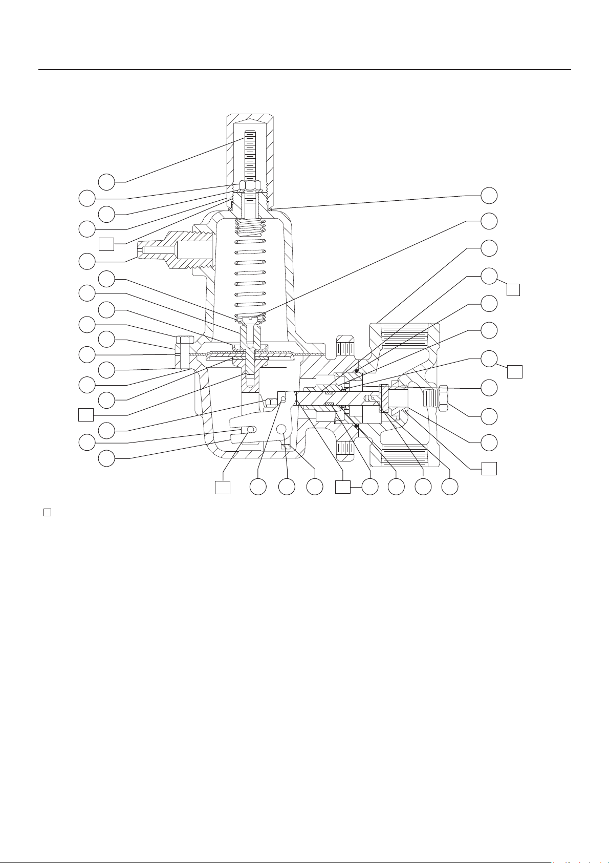
Type 627F
Key Description
1 Body
2* Orice
3 Cap Screw
4* Diaphragm Case O-ring
5 Diaphragm Case
6 Boost Body
7* O-ring
8 Stem Guide
9* Disk Assembly
10 Stem
11* Stem O-ring
12* Stem Backup Ring
13 Hair Pin Clip
14 Drive Pin
15 Lever
16 Lever Retainer
17 Lever Pin
18 Lever Cap Screw
19A Pusher Post
19B Drive Pin
23* Diaphragm
24 Diaphragm Head
29 Spring Case
31 Lower Spring Seat
32 Tension Spring
34 Locknut
36 Closing Cap
37 Spring Case Cap Screw
39 Nameplate
53 Spring Retainer
54 Diaphragm Connection
55* Gasket
56 Reducing Nipple
58 Pipe Plug
59 Elbow (optional)
60 Pilot Supply Tubing (optional)
61 Spring Seat Bolt
62 Washer
63* Closing Cap Gasket
67 Drive Screw
*Recommended spare part.
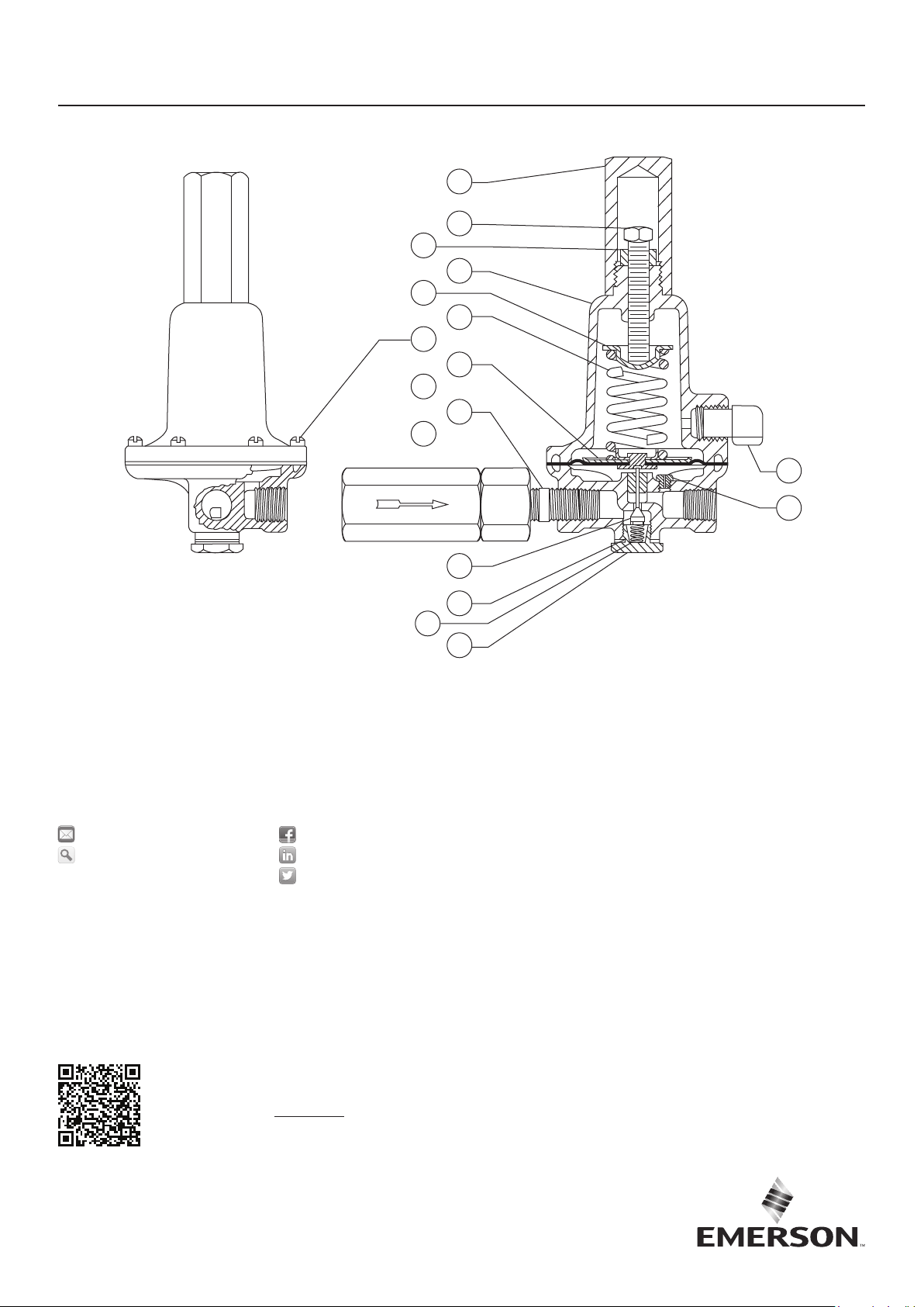
Type 6351F
Key Description
1 Body Assembly
2 Spring Case
3 Body Plug Assembly
4* Inner Valve Plug
6* Valve Spring
7* Diaphragm Assembly
8 Upper Spring Seat
9 Control Spring
10 Adjusting Screw
11 Locknut
12 Machine Screw
22 Pipe Nipple
23 Body Plug Gasket
24 Filter, Type P594-1 (optional)
28 Closing Cap
35 Vent Assembly,
Type Y602X1-A12
44 Restriction
2
34
36
56
54
37
23
24
L1
19
61
62
L1
32
31
29
55
18
15
Type 627F
63
53
1
10
L2
4
8
7
5
L2
6
58
2
L2
32B3310_E
APPLY LUBRICANT
L1 = MULTI-PURPOSE NLGI GRADE 1 GREASE*
L2 = ANTI-SEIZE COMPOUND
1. Lubricants must be selected such that they meet the temperature requirements.
*NLGI is the National Lubricating Grease Institute.
(1)
L2
Figure 1. Type 627F Main Regulator Assembly
L2
9131211161714
3
Type 627F
28
10
11
2
8
9
12
7
1
22
24
35
44
32B3797_D
Webadmin.Regulators@emerson.com
Fisher.com
Emerson Automation Solutions
Americas
McKinney, Texas 75070 USA
T +1 800 558 5853
+1 972 548 3574
Europe
Bologna 40013, Italy
T +39 051 419 0611
For further information on the current
PED revision see Bulletin: D103053X012
or scan the QR code.
4
23
6
3
Figure 2. Type 6351F Pilot Assembly
Facebook.com/EmersonAutomationSolutions
LinkedIn.com/company/emerson-automation-solutions
Twitter.com/emr_automation
Asia Pacic
Singapore 128461, Singapore
T +65 6777 8211
Middle East and Africa
Dubai, United Arab Emirates
T +971 4 811 8100
D101545X014 © 2002, 2019 Emerson Process Management Regulator
Technologies, Inc. All rights reserved. 06/19.
The Emerson logo is a trademark and service mark of Emerson
Electric Co. All other marks are the property of their prospective owners.
Fisher™ is a mark owned by Fisher Controls International LLC, a
business of Emerson Automation Solutions.
The contents of this publication are presented for information purposes
only, and while eort has been made to ensure their accuracy, they are
not to be construed as warranties or guarantees, express or implied,
regarding the products or services described herein or their use or
applicability. All sales are governed by our terms and conditions, which
are available on request. We reserve the right to modify or improve the
designs or specications of our products at any time without notice.
Emerson Process Management Regulator Technologies, Inc does not
assume responsibility for the selection, use or maintenance of any
product. Responsibility for proper selection, use and maintenance of any
Emerson Process Management Regulator Technologies, Inc. product
remains solely with the purchaser.
 Loading...