

Page 1
Panda 6000i PMS
Super silent technology
230V 50Hz 6kW
Fischer Panda GmbH
Panda_6000i_System_eng_s01835.book.R01 16.1.09
Page 2

Revision
Document
Akcuell: Panda_6000i_System_eng_s01835.book.R01_16.1.09
Replace
Revision Page
Copyright
Duplication and change of the manual is permitted only in consultation with the manufacturer!
Fischer Panda GmbH, 33104 Paderborn, reserves all rights regarding text and graphics. Details are given to
the best of our knowledge. No liability is accepted for correctness. Technical modifications for improving
the product without previous notice may be undertaken without notice. Before installation, it must be ensured that the pictures, diagrams and related material are applicable to the genset supplied. Enquiries must be
made in case o doubt.
2
Page 3

Table of contents
Panda 6000i PMS.................................................................................................................... 1
Revision................................................................................................................................... 2
A Panda 6000i system....................................................................................................... 7
A.1 Components ..................................................................................................................... 7
A.2 Range of operation ........................................................................................................... 8
A.2.1 Main features of the Panda 6000i ....................................................................................... 8
Panda 6000i............................................................................................................................. 9
Part 1: Generator Manual....................................................................................................... 9
Current revision status........................................................................................................ 10
Safety first............................................................................................................................. 12
Tools...................................................................................................................................... 13
Safety Precautions............................................................................................................... 15
B Panda 6000i PMS generator....................................................................................... 19
B.1 Type plate at the generator ........................................................................................... 19
B.2.1 Right side view .................................................................................................................. 20
B.2.2 Left side view ..................................................................................................................... 21
B.2.3 Front view .......................................................................................................................... 22
B.2.4 Back view .......................................................................................................................... 23
B.2.5 View from above ................................................................................................................ 24
B.3 Details of function units ................................................................................................ 25
B.3.1 Remote control panel - See Panda iControl manual ......................................................... 25
B.3.2 Components of the cooling system (raw- and freshwater) ................................................ 25
B.3.3 Components of the fuel, air intake and exhaust system .................................................... 26
B.3.4 Components of the electrical system ................................................................................ 27
B.3.5 Components of the lubrication system .............................................................................. 28
B.3.6 Sensors and switches for operating surveillance .............................................................. 29
B.4 Operation instructions - See Panda iControl panel manual ....................................... 30
B.4.1 Daily routine checks before starting - See Panda iControl manual ................................... 30
B.4.2 Starting generator - See Panda iControl manual .............................................................. 30
B.4.3 Stopping the generator - See Panda iControl manual ....................................................... 30
C Installation Instructions .............................................................................................. 31
C.1 Placement ....................................................................................................................... 31
C.1.1 Advice for optimal sound insulation ................................................................................... 31
C.2 Generator connections .................................................................................................. 32
C.3 Cooling system installation - Raw water ...................................................................... 33
C.3.1 General information ........................................................................................................... 33
C.3.2 Installation of the thru hull fitting in yachts ......................................................................... 33
C.3.3 Quality of the raw water sucking in line ............................................................................. 33
C.3.4 Generator installation above waterline .............................................................................. 34
C.3.5 Generator installation below waterline .............................................................................. 35
C.3.6 Indirect cooling of the genset housing (by the heat exchanger) ........................................ 36
16.1.09 Panda_6000i_System_eng_s01835.book.R01 - Table of contents Page 3
Page 4

Table of contents
C.4 The freshwater coolant circuit .......................................................................................37
C.4.1 Position of the external cooling water expansion tank .......................................................37
C.4.2 Pressure test for controlling the cooling water circuit ........................................................ 37
C.4.3 Scheme for freshwater circuit at two circuit cooling system ..............................................38
C.5 Water-cooled exhaust system .......................................................................................39
C.5.1 Installation of the standard exhaust system .......................................................................39
C.5.2 Exhaust / water separator ..................................................................................................40
C.5.3 Installation exhaust-water-separator ..................................................................................41
C.6 Installation of the fuel system .......................................................................................43
C.6.1 General references ............................................................................................................ 43
C.6.2 The electrical fuel pump .....................................................................................................44
C.6.3 Connection of the fuel lines at the tank ..............................................................................44
C.6.4 Position of the pre-filter with water separator ....................................................................45
C.7 Generator 12VDC system installation ...........................................................................46
C.7.1 Connection of the 12V starter battery ................................................................................ 46
C.7.2 Connection of the remote control panel - See Panda iControl panel manual ....................46
C.8.1 Installation PMGi inverter - See separat PMGi 6000 inverter manual ...............................48
D Generator Failure..........................................................................................................49
D.1 Tools and measuring instruments ................................................................................49
D.2 Overloading the generator .............................................................................................49
D.2.1 Low generator-output voltage ............................................................................................ 50
D.3 Starting problems ...........................................................................................................50
D.3.1 Fuel solenoid valve ............................................................................................................ 50
D.3.2 Dirty fuel filter .....................................................................................................................51
D.4 Troubleshooting table ....................................................................................................51
E Maintenance Instructions............................................................................................53
E.1 General maintenance instructions ................................................................................53
E.1.1 Checks before starting .......................................................................................................53
E.1.2 Check of hoses and rubber parts in the sound insulated capsule ..................................... 53
E.2 Oil change intervals ........................................................................................................53
E.2.1 Execution of an oil change .................................................................................................54
E.3 Ventilating the fuel system ............................................................................................57
E.3.1 Replace of the fuel filter ..................................................................................................... 58
E.3.2 Checking the water separator in the fuel supply ................................................................59
E.4 Replace the air filter mat ................................................................................................60
E.5 Ventilation of the Coolant Circuit / Freshwater ............................................................61
E.6 Replace of the v-belt for the internal cooling water pump .........................................63
E.7 The Raw water circuit ..................................................................................................... 65
E.7.1 Clean raw water filter ......................................................................................................... 65
E.7.2 Reason for frequent impeller wear .....................................................................................65
E.7.3 Replace the impeller .......................................................................................................... 66
E.8 Conservation of the generator (long operation interruption) .....................................68
E.8.1 Measures for preparation of winter storage ....................................................................... 68
E.8.2 Initiation during spring ........................................................................................................69
F Tables............................................................................................................................71
F.1 Troubleshooting .............................................................................................................71
Page 4 Panda_6000i_System_eng_s01835.book.R01 - Table of contents 16.1.09
Page 5

Table of contents
F.2 Technical data ................................................................................................................ 74
F.2.1 Technical data generator ................................................................................................... 74
F.2.2 Technical data engine ....................................................................................................... 75
F.3 Engine oil specification ................................................................................................. 77
F.4 Coolant specifications ................................................................................................... 78
Panda i-series....................................................................................................................... 79
Part 2: Panel Panda iControl Manual.................................................................................. 79
Current revision status........................................................................................................ 80
A Panda iControl ............................................................................................................. 81
A.1 Safety instructions ......................................................................................................... 82
A.2 Connection of the iControl ............................................................................................ 82
A.3 Buttons and display of the iControl ............................................................................. 83
A.4 Engine control ................................................................................................................ 84
A.5 Operation manual ........................................................................................................... 84
A.5.1 Daily routine checks before starting .................................................................................. 84
A.5.2 General .............................................................................................................................. 85
A.5.3 Long time run of the generator .......................................................................................... 86
A.5.4 Start of the generator ........................................................................................................ 86
A.5.5 Stop of the generator ......................................................................................................... 87
A.5.6 Automatic start .................................................................................................................. 87
A.5.7 Additional information ........................................................................................................ 87
A.6 Error warnings ................................................................................................................ 88
A.7 Errors ............................................................................................................................... 88
A.8 Electronic board ............................................................................................................. 89
A.8.1 Location at the Panda i-series generator .......................................................................... 89
A.9 Technical data ................................................................................................................ 90
A.9.1 Intended use ...................................................................................................................... 90
A.9.2 Dimensions ........................................................................................................................ 91
Panda i-series....................................................................................................................... 93
Part 3: PMGi 6000 inverter Manual...................................................................................... 93
Current revision status........................................................................................................ 94
A Panda PMGi 6000........................................................................................................ 95
A.1 Safety instruction ........................................................................................................... 96
A.2 Type plate ........................................................................................................................ 96
A.3 Front side/connection side ............................................................................................ 97
A.3.1 Socket pins of the PMGi 6000 ........................................................................................... 97
A.4 Back side - Top side ....................................................................................................... 98
A.5 Operation manual ........................................................................................................... 99
A.5.1 Primary remarks / Winter operation ................................................................................... 99
16.1.09 Panda_6000i_System_eng_s01835.book.R01 - Table of contents Page 5
Page 6

Table of contents
A.5.2 Load at the PMGi ............................................................................................................... 99
A.5.3 Automatic start ................................................................................................................... 99
A.6 Status LED´s ...................................................................................................................99
A.7 Cooling of the PMGi .....................................................................................................100
A.8 Installation of the PMGi ................................................................................................100
A.8.1 Electrical connection. .......................................................................................................100
A.8.2 Installation of the ferrites ..................................................................................................101
A.9 Technical Data .............................................................................................................. 102
A.9.1 General Data ................................................................................................................... 102
A.9.2 Generator Spezifikation ................................................................................................... 102
A.9.3 PMGi out .......................................................................................................................... 103
A.10 PMGi protections ..........................................................................................................104
A.10.1 Overload - switch point ....................................................................................................104
A.10.2 Short circiut ......................................................................................................................104
A.10.3 Under voltage and signal .................................................................................................104
A.10.4 Overheat ..........................................................................................................................105
Page 6 Panda_6000i_System_eng_s01835.book.R01 - Table of contents 16.1.09
Page 7
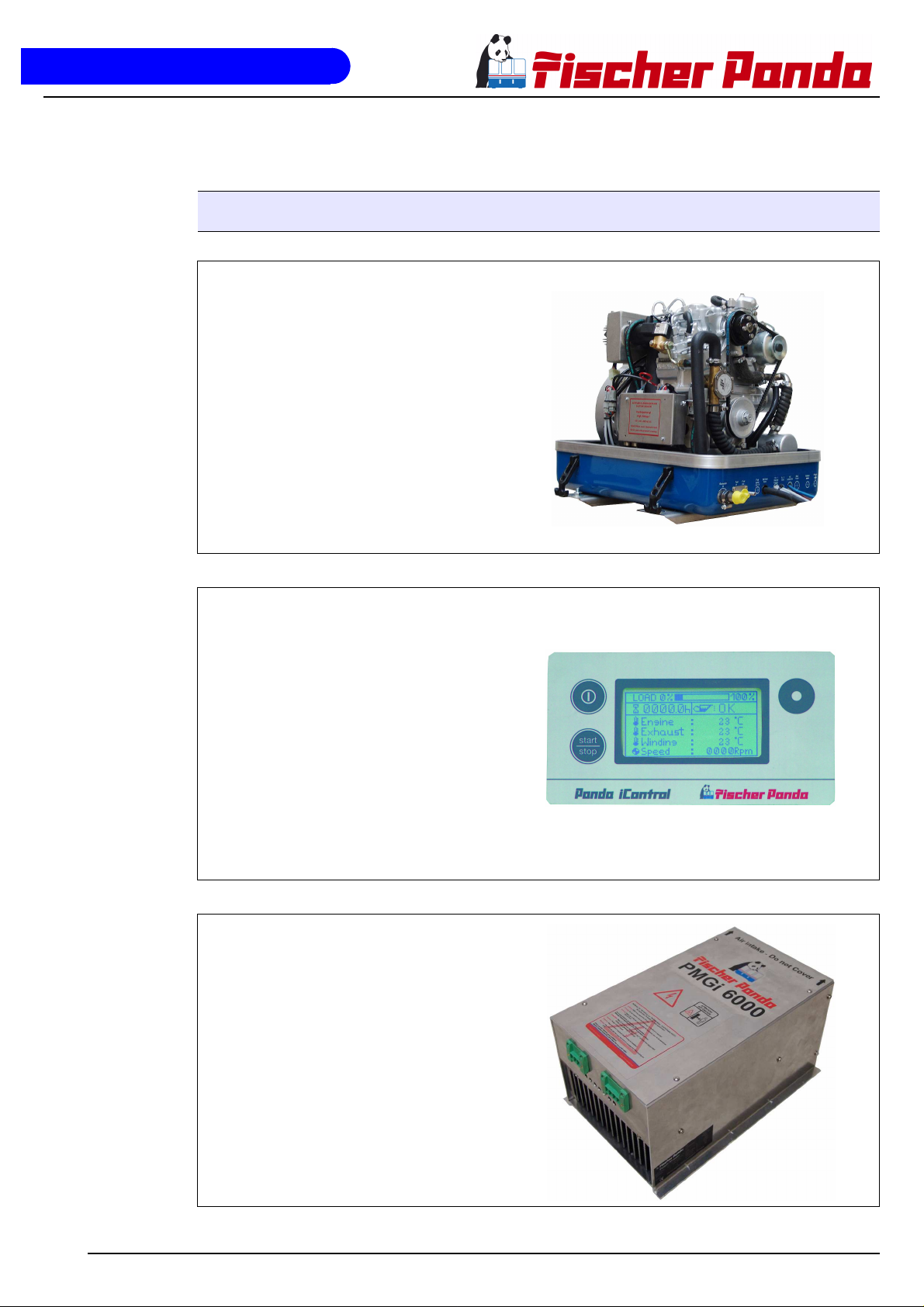
Panda 6000i system
A. Panda 6000i system
A.1 Components
1. Panda 6000i PMS Generator
Permanent-Magnet-Generator
Art. no. C10060BX1SV01
Manual see “Part 1: Generator Manual” on
page 9.
Fig. A.1-1: Panda 6000i generator
2. Panel Panda iControl with
electronic board at the generator
Art no. 21.02.02.011H (Panel)
Art no. 21.02.01.005H (electronic board)
Manual see “Part 2: Panel Panda iControl
Manual” on page 79.
Fig. A.1-2: iControl panel
3. Panda PMGi 6000 Inverter AC/AC
6kW 230V / 50Hz
Art. no. 21.07.03.008P
Manual see “Part 3: PMGi 6000 inverter
Manual” on page 93.
Fig. A.1-3: PMGi 6000 inverter
16.1.09 Panda_6000i_System_eng_s01835.book.R01 - Chapter A: Panda 6000i system Page 7
Page 8

A.2 Range of operation
Reliable power supply on sailing boats.
A.2.1 Main features of the Panda 6000i
• Extremely high starting capacity, perfect for a Bauer junior II compressor or air conditioner!
• 230V / 50Hz system for all your domestic appliances!
• Compact and light, takes up less space!
• Super silent sound insulation capsule!
• Graphical Display, easy to operate!
Panda 6000i system
• Option for reduce speed at lower loads, saves fuel!
• Pure sinus wave, higher frequency and voltage stability!
• Optimized engine rpm (2800 rpm) for a long generator life!
Page 8 Panda_6000i_System_eng_s01835.book.R01 - Chapter A: Panda 6000i system 16.1.09
Page 9
Panda 6000i
Part 1: Generator Manual
Panda 6000i PMS
230V/50Hz 6kW
Fischer Panda GmbH
Page 10
Current revision status
Document
Actual: Panda 6000i generator_s01835_eng.R01_16.1.09
Replace:
Revision Page
10
Page 11
Icemaster GmbH Fischer Marine
since
1977
since
1978
since
1988
since
1988
since
1988
Generators
Conclusion Fischer -
Icemaster GmbH
100 % water cooled Pan-
da generators
Panda Vehicle Genera-
tors
Fischer Panda
FISCHER GENERATORS have been manufactured since 1978 and are a well-known brand for first class diesel
generators with especially effective sound-insulation. Fischer has been one of the leading manufacturers in respect of
quality and know-how during this period.
FISCHER, as the worldwide manufacturer of modern marine diesel generators, developed the Sailor-Silent series for
example and produced a GPR sound-insulated capsule as early as 1979 and the basis for new generator technology.
The companies Fischer and Icemaster amalgamated under the direction of Icemaster in 1988, in order to concentrate
on the development of new products. Production was moved to Paderborn.
The amalgamation of the two qualified companies led to the development of a complete new programme within a short
space of time. The generator sets developed at that time set new technological standards worldwide.
The generators became more efficient and powerful than other generators in the same nominal performance range,
because of the improved cooling. Panda generator demonstrated its superiority in several tests by renowned institutes
and magazines during the past years. The patented VCS (voltage Control System) means it can meet all demands
including motor speed. The start-booster (ASB) means Panda generators meet the highest demands in respect of
voltage stability and starting values A Panda generator, with the same drive motor, produces 15 % more effective output
than the majority of conventional generators. This superiority in efficiency also ensures a fuel saving to the same extent.
The 100 % water-cooled Panda generators are currently manufactured in the performance range from 2 to 100 kW in
various versions. Fast running motors are preferred for performances up to approx. 30 kW (nominal speed 3.000 rpm).
The heavier slow runners are preferred for the higher range. The fast running generators have proved themselves
many times for many uses, that they meet the demands in quality of yachts and vehicles, and offer space and weight
saving of 50 % compared to slow running generators.
In addition to the Panda series, Fischer Panda also supply the super compact high-tech sound-insulated battery
charging generators from the DC/AC Panda AGT series, which is a very interesting solution for the production of mobile
power.
The new HTG-alternators ensure that a charging rate of 285 amps is achieved that was scarcely thought possible for
this compact construction. This alternator replaces a separate shipboard generators (constant 230 volts AC with up to
3500 kW from the main machine)
Fischer Panda GmbH, 33104 Paderborn, reserves all rights regarding text and graphics. Details are given to the best of our knowledge. No liability is accepted for
correctness. Technical modifications for improving the product without previous notice may be undertaken without notice. Before installation, it must be ensured that the
pictures, diagrams and related material are applicable to the aggregate supplied. Enquiries must be made in case of doubt.
11
Page 12
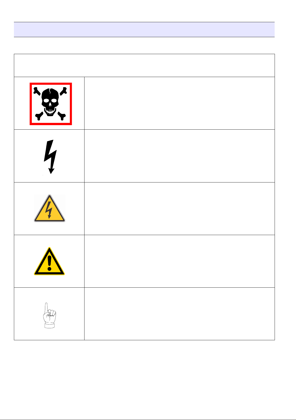
Safety first
These symbols are used throughout this manual and on labels on the maschine itself to warn of the possibility of
personal injutry. Read these instructions carefully. It is essential that you read the instructions and safety regulations
before you attempt to assemble or use unit.
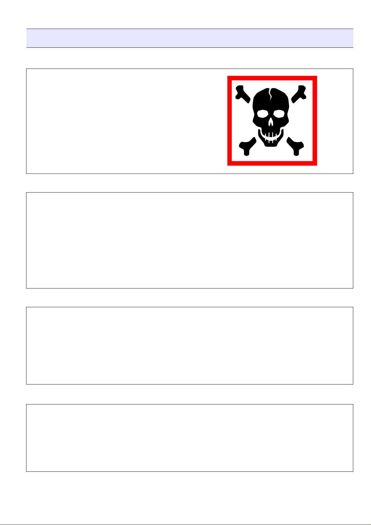
This danger symbol refers to toxic danger and draws attention to special warnings,
instructions or procedures which, if not strictly observed, may result in severe
personal injury or loss of life.
This danger symbol refers to electric danger and draws attention to special
warnings, instructions or procedures which, if not strictly observed, may result in
electrical shock which will result in severe personal injury or loss of life.
This danger symbol refers to electric danger and draws attention to special
warnings, instructions or procedures which, if not strictly observed, may result in
electrical shock which will result in severe personal injury or loss of life.
This warning symbol draws attention to special warnings, instructions or procedures
which, if not strictly observed, may result in damage or destruction of equipment,
severe personal injury or loss of life.
This warning symbol draws attention to special warnings, instructions or procedures
which, if not strictly observed, may result in damage or destruction of equipment
12
Page 13
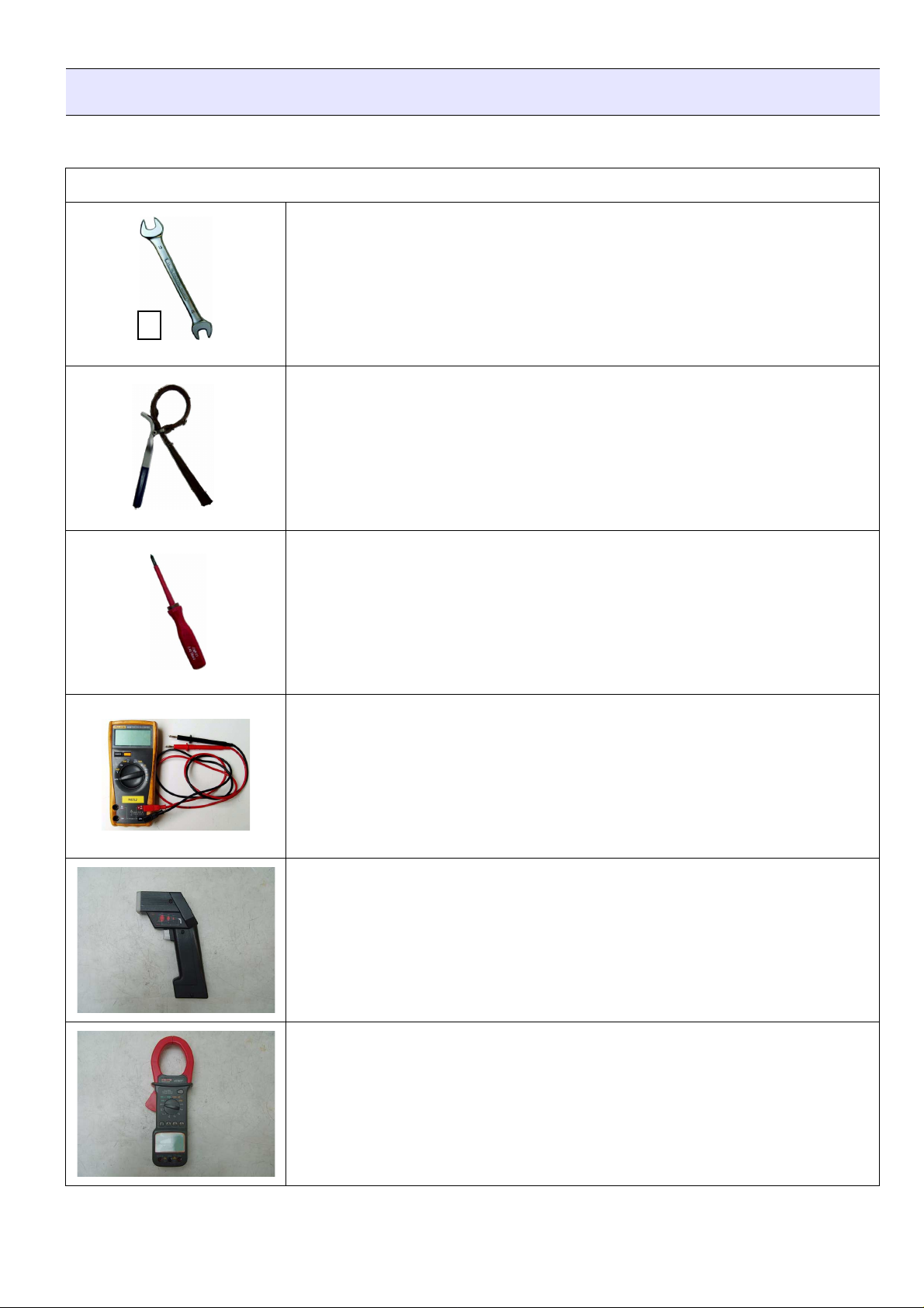
Tools
X
This symbols are used throughout this manual to show which tool must be used at maintenance or installation.
Spanners
X = number of spanner
Hook wrench for oil filter
Screw driver, for slotted head screws and for recessed head screws
Multimeter, multimeter with capacitor measuring
Infrared temperature mesuring pistol
Current clamp (DC for synchron generators; AC for asynchron generators)
13
Page 14
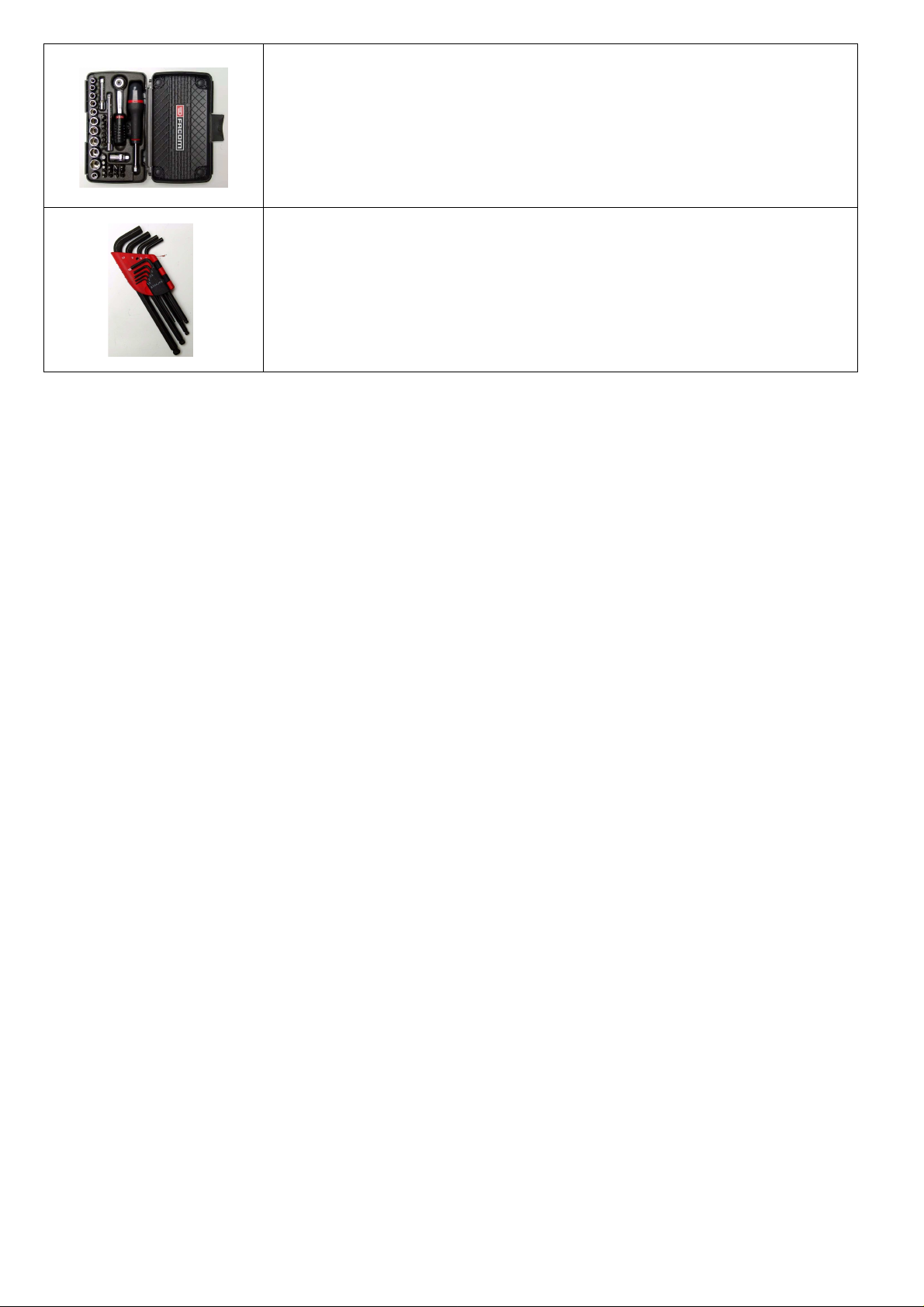
Socket wrench set
Hexagon wrench keys
14
Page 15
Safety Precautions
CALIFORNIA
Proposition 65 Warning
Diesel engine exhaust and some of its constituents
are known to the State of California to cause cancer,
birth defects, and other reproductive harm.
Manufacturer declaration in terms of the machine guideline 98/37/EG .
The generator is in such a way developed that all assembly groups correspond to the CE guidelines. If machine guideline 98/37/EG is applicable, then it is forbidden to bring the generator into operation until it has been determined
that the system into which the generator is to be installed in also corresponds to the regulations of the machine guideline 98/37/EG. This concerns among other things the exhaust system, cooling system and the electrical installation.
The evaluation of the "protection against contact" can only be accomplished in connection with the respective
system. Likewise among other things responsibility for correct electrical connections, a safe ground wire connection,
foreign body and humidity protection, protection against humidity due to excessive condensation as well as the overheating through appropriate and inappropriate use in its installed state on the respective machine lies within the
responsibility of those who undertake installation of the generator in the system.
Use the advantages of the customer registration:
• Thus you receive extended product information, which are sometimes safety-relevant
• You receive free upgrades, if necessary
Further advantages:
With your full information, the Fischer Panda technicians can give you fast assistance, since 90 % of the distur-
bances result from errors in the periphery.
Problems according to errors in the installation can be recognized in advance.
Attention, Important Directions regarding Operation!
1. The installation certificate must be completed when taken into use, and certified by a signature.
2. The installation certificate must be despatched within two weeks of use to Fischer Panda.
3. The official guaranty confirmation will be completed by Fischer Panda after receipt and sent to the customer.
4. A guaranty must be shown to make any claims.
Claims against the guaranty will not be accepted of the above said instructions are not, or only partially, carried out.
15
Page 16
The electrical Installations may only be carried out by trained and
examined personnel!
The generator may not be taken into use with the cover removed.
The rotating parts (belt-pulley, belts, etc) must be covered and protected so that there is no danger to life and body!
If a sound insulation cover must be produced at the place of installation, then well-placed signs must show that the
generator can only be switched on with a closed capsule.
All servicing-, maintenance or repair work may only be carried out, when the motor is not running.
Electrical power: DANGER TO LIFE!
Electrical voltages above 48 volts (battery chargers greater than 36 volts) are always dangerous to
life). The rules of the respective regional authority must be adhered to. Only an electrician may
carry out installation of the electrical connections for safety reasons.
General safety references for the enterprise of a generator.
With all energized systems, with which the current is more than 50 Ampère, special safety precautions must be
made, in order to protect the environment of the components against fire.
It is to be ensured absolutely that at the battery a main switch in well accessible place is accommodated, so that with
danger of the main switches can be separated immediately. The main switch must be however also directly at the
battery installed. If this place is not well accessible, a power relay must be used instead of the main switch which can
be served manually, which can be served then if necessary from different places. The switches for the power relay
are to mark accordingly as main switches DC battery "with danger switch off!".
ATTENTION!
Do not connect the minus pole of the starter battery to the ground of the boat because of galvanic reason.
CAUTION!
Contact of the electrical contacts may be DANGER TO LIFE!
The PMGi cable must be secured at the generator and at the PMGi with appropriate safety devices.
The generator is also included into the CO2 - fire-extinguishing system.
Fire protection measures
All construction units in the environment of energized parts, which carry more than 50 Amp., must be fire protectionmoderately secured.
All junction points at the energized parts must be examined on heating up regularly (infrared thermometers).
16
Page 17

Safety Instrictions for handling batteries
These instructions must be noticed additionally to the instructions of the battery manufacturer:
• If the batteries are working, someone should be in your near area to help you in a case of emergency.
• Water and soap must be hold ready if battery acid corrode your skin.
• Wear eye protection and protective clothing. During working with the batteries don´t touch the eyes.
• If you got an acid splash on your skin or clothing, wash it out with much water and soap.
• If you got acid in your eyes, rinse them immediately with clear water until no cauterization is noticeable. Visit a doctor immediately.
• Don´t smoke in the area of the batteries. Avoid open fires. In the area of batteries there is a danger of explosions.
• Pay attention that no tools will fall on the battery poles, if necessary cover them up.
• During the installation, don´t wear a wrist watch or arm jewels, under these circumstances you can create a battery
short-circuit. Skin burnings could be the result.
• Protect every battery contact against unintentional touch.
• Use only cyclical profoundly dischargeable batteries. Starter batteries are not appropriate. Lead-gel batteries are
commended. They are maintenance-free, profoundly dischargeable and produce no gas.
• Do not charge a frozen battery.
• Avoid a battery short-curcuit.
• Take care that the battery is good ventilated in order to drain off developing gas.
• The battery connection terminals must be checked for tightness before operating.
• The battery connection cable must be mounted carefully. Check for incorrect heating at operation with load. The
vibrating devices must be checked regulary for scour points and flaw in the isolation.
Technical Support by Internet: [email protected]
17
Page 18

Intentionally Blank
18
Page 19
Panda 6000i PMS generator
B. Panda 6000i PMS generator
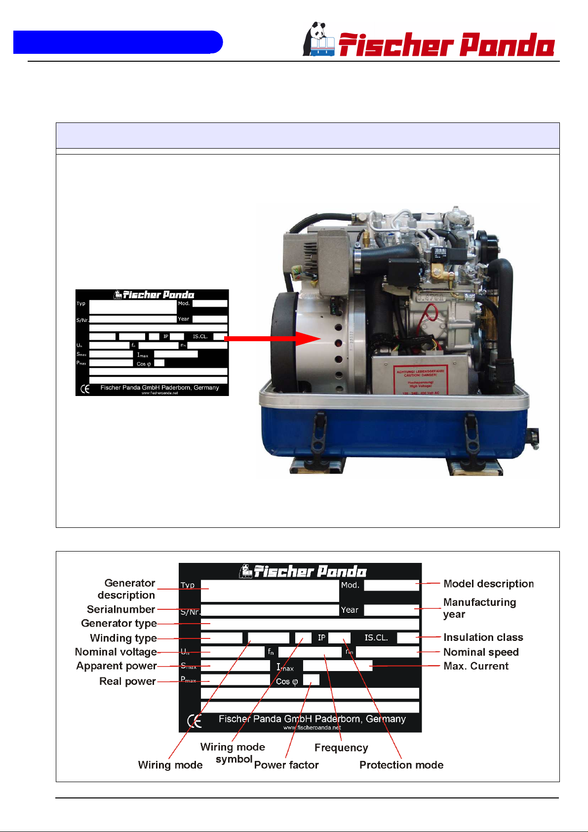
B.1 Type plate at the generator
Fig. B.1-1: Type plate
Fig. B.1-2: Discription type plate
16.1.09 Panda 6000i generator_s01835_eng.R01 - Chapter: B: Panda 6000i PMS generator Page 19
Page 20
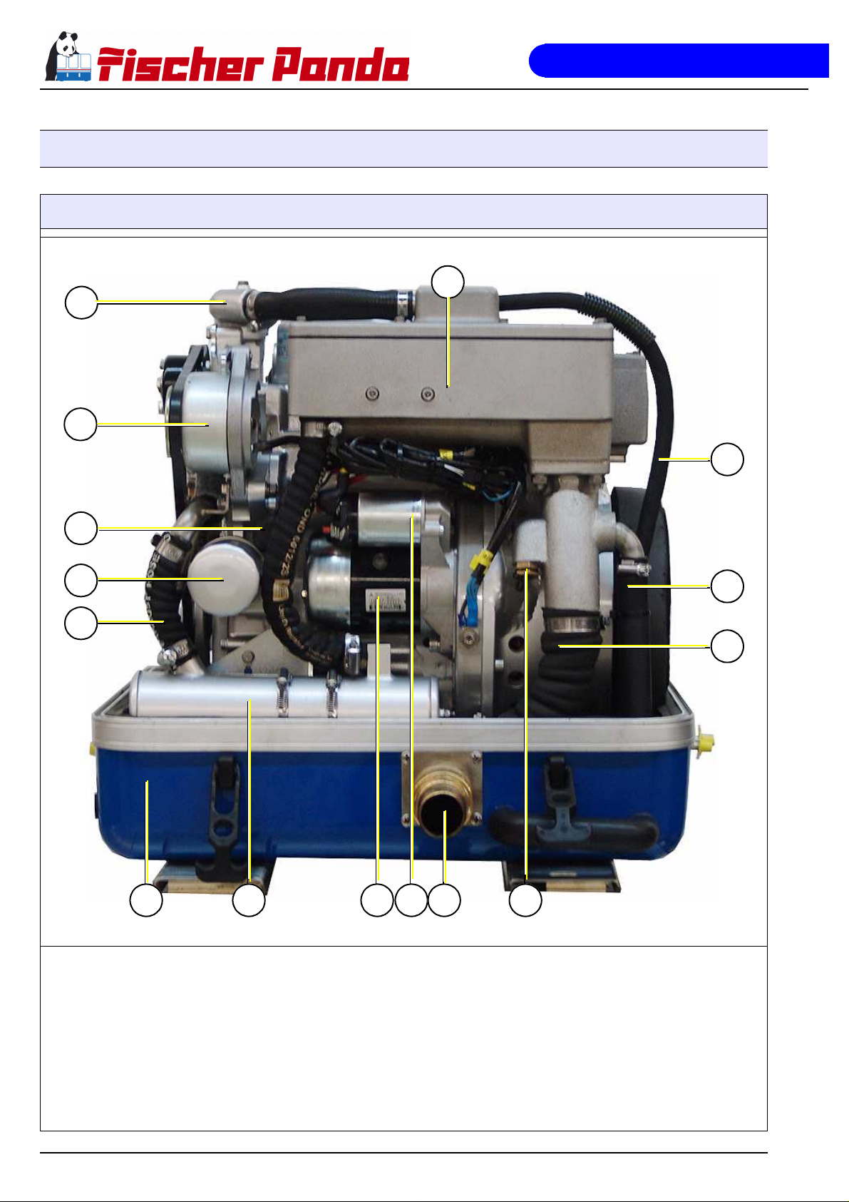
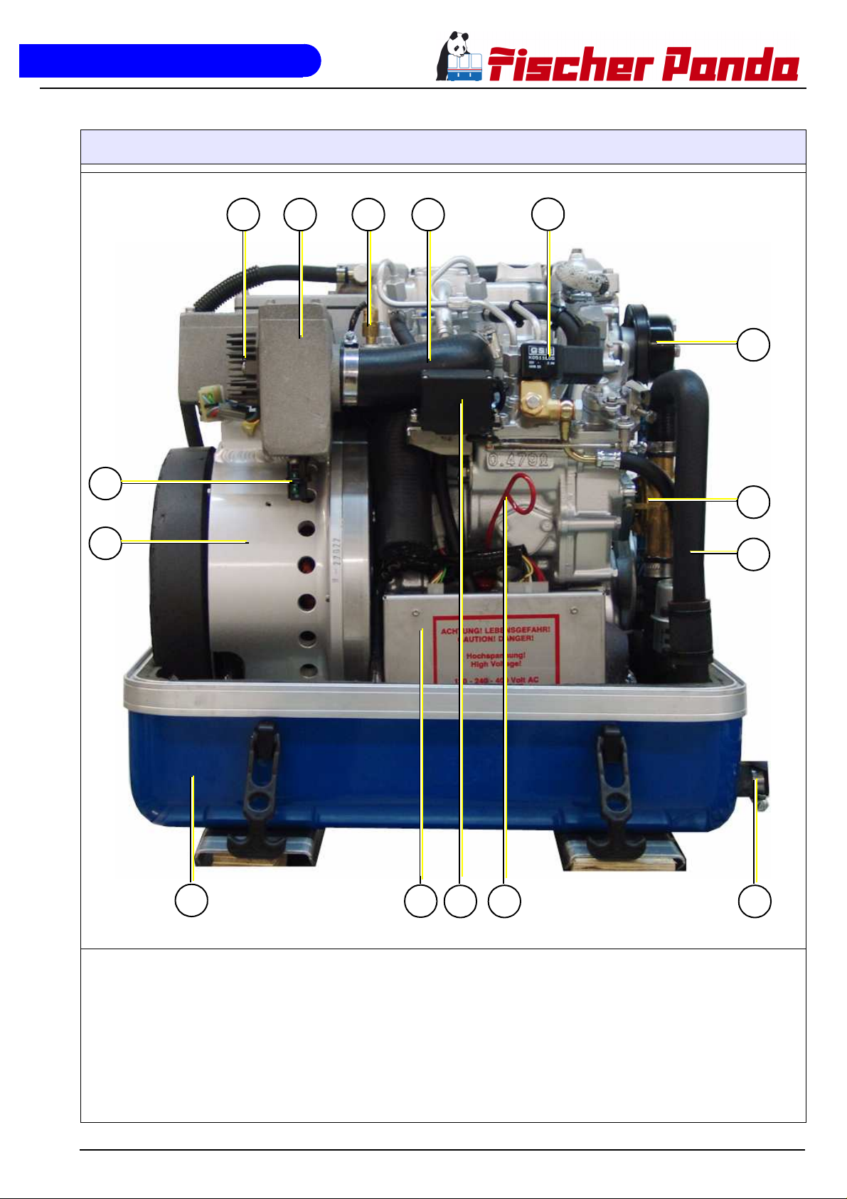
B.2 Description of the generator
01
03
04
06
12
02
05
07 08 09 1110
13
14
15
01) Thermostat housing
02) DC-alternator 12V
03) Oil pressure switch
04) Oil filter
05) Cooling water pipe, heat exchanger - water pump
06) Sound cover base part
07) Heat exchanger
08) Starter motor
09) Solenoid switch for starter motor
10) Exhaust outlet
11) Thermosensor
12) Exhaust hose
13) Raw water injection pipe
14) Ventilation pipe to external expansion tank
15) Watercooled exhaust elbow
B.2.1 Right side view
Panda 6000i PMS generator
Page 20 Panda 6000i generator_s01835_eng.R01 - Chapter: B: Panda 6000i PMS generator 16.1.09
Fig. B.2.1-1: Right side view
Page 21
Panda 6000i PMS generator
03
08
11
02
04
05 06 07
10
14
09
15
01
13 12
01) Electrical fuse 30A for starter motor
02) Generator housing with coil
03) Sound cover base part
04) Housing with iControl electronic board (DO NOT OPEN)
05) Actuator
06) Oil dipstick
07) Raw water intake
08) Raw water intake pipe
09) Raw water pump
10) Pulley for internal cooling water pump
11) Fuel solenoid switch
12) Suction hose, air suction housing - induction elbow
13) Thermoswitch cylinder head
14) Air suction housing
15) Charge controller for DC-alternator
B.2.2 Left side view
16.1.09 Panda 6000i generator_s01835_eng.R01 - Chapter: B: Panda 6000i PMS generator Page 21
Fig. B.2.2-1: Left side view
Page 22
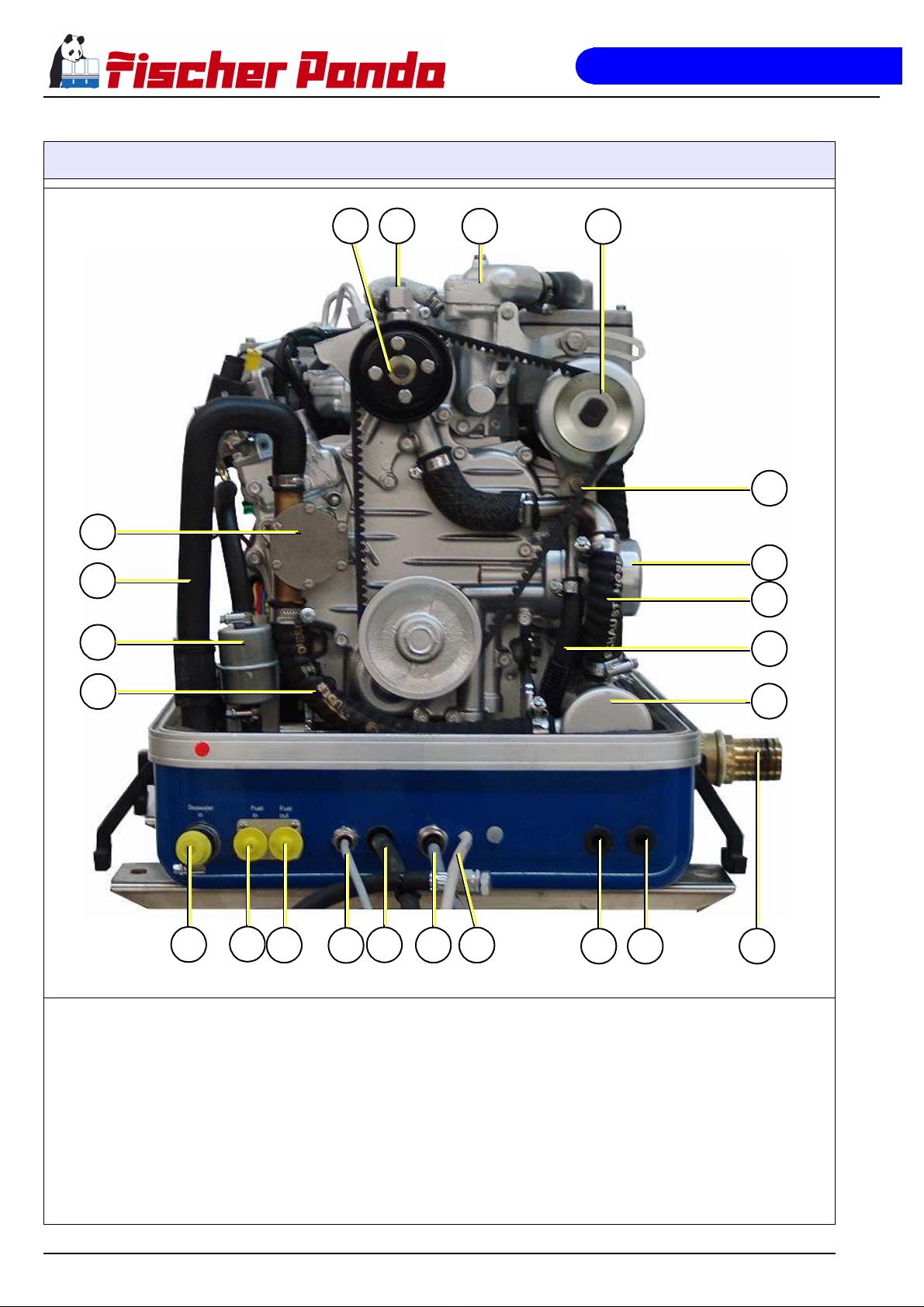
B.2.3 Front view
06
05
22
09
10
14
07
08
21
20
15
17
18
16
02
01
03
04
19
11
12 13
23
01) Raw water pump
02) Raw water intake hose
03) Fuel filter
04) Raw water hose, raw water pump - heat exchanger
05) Raw water intake
06) Fuel IN
07) Fuel OUT
08) Cable for fuel pump
09) Oil drain hose
10) Cable for generator output AC out
11) Cable for iControl panel
12) Passage for starter battery cable (-)
13) Passage for starter battery cable (+)
14) Exhaust outlet
15) Heat exchanger
16) Injection pipe from external expansion tank
17) Cooling water pipe, heat exchanger - water pump
18) Oil filter
19) V-belt
20) DC-alternator 12V
21) Thermostat housing
22) Ventilation screw internal cooling water pump
23) Pulley for internal cooling water pump
Panda 6000i PMS generator
Page 22 Panda 6000i generator_s01835_eng.R01 - Chapter: B: Panda 6000i PMS generator 16.1.09
Fig. B.2.3-1: Front view
Page 23
Panda 6000i PMS generator
04
11
13
14
10
06 07 08
01
02
03
09
05
12
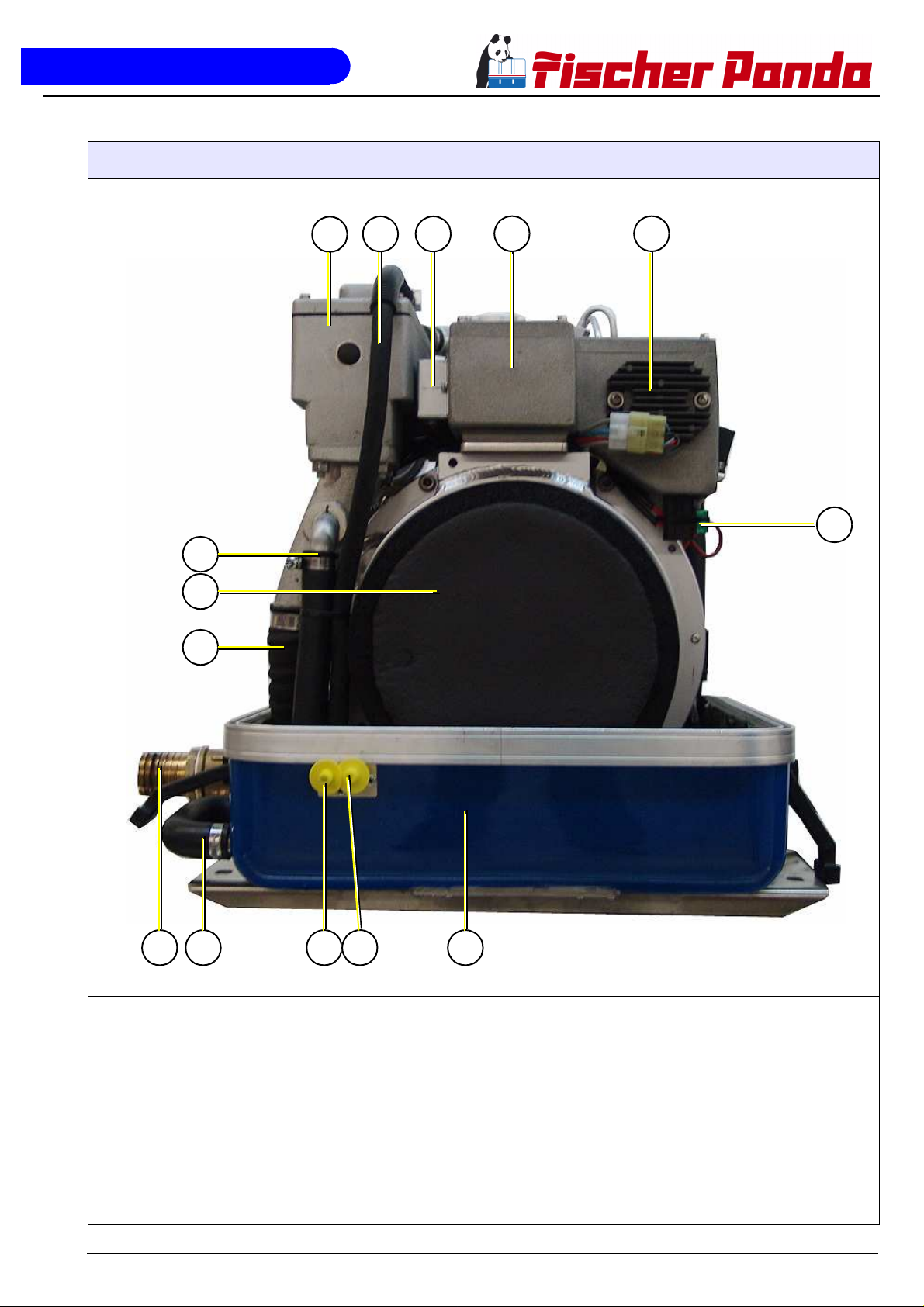
01) Raw water injection pipe
02) Generator front cover
03) Exhaust hose
04) Exhaust outlet
05) Connection for external ventilation valve
06) Connection from external expansion tank
07) Connection to external expansion tank
08) Sound cover base part
09) Electrical fuse 30A for starter motor
10) Charge controller for DC-alternator
11) Air suction housing
12) Actuator power modul
13) Ventilation pipe to external expansion tank
14) Watercooled exhaust elbow
B.2.4 Back view
16.1.09 Panda 6000i generator_s01835_eng.R01 - Chapter: B: Panda 6000i PMS generator Page 23
Fig. B.2.4-1: Back view
Page 24
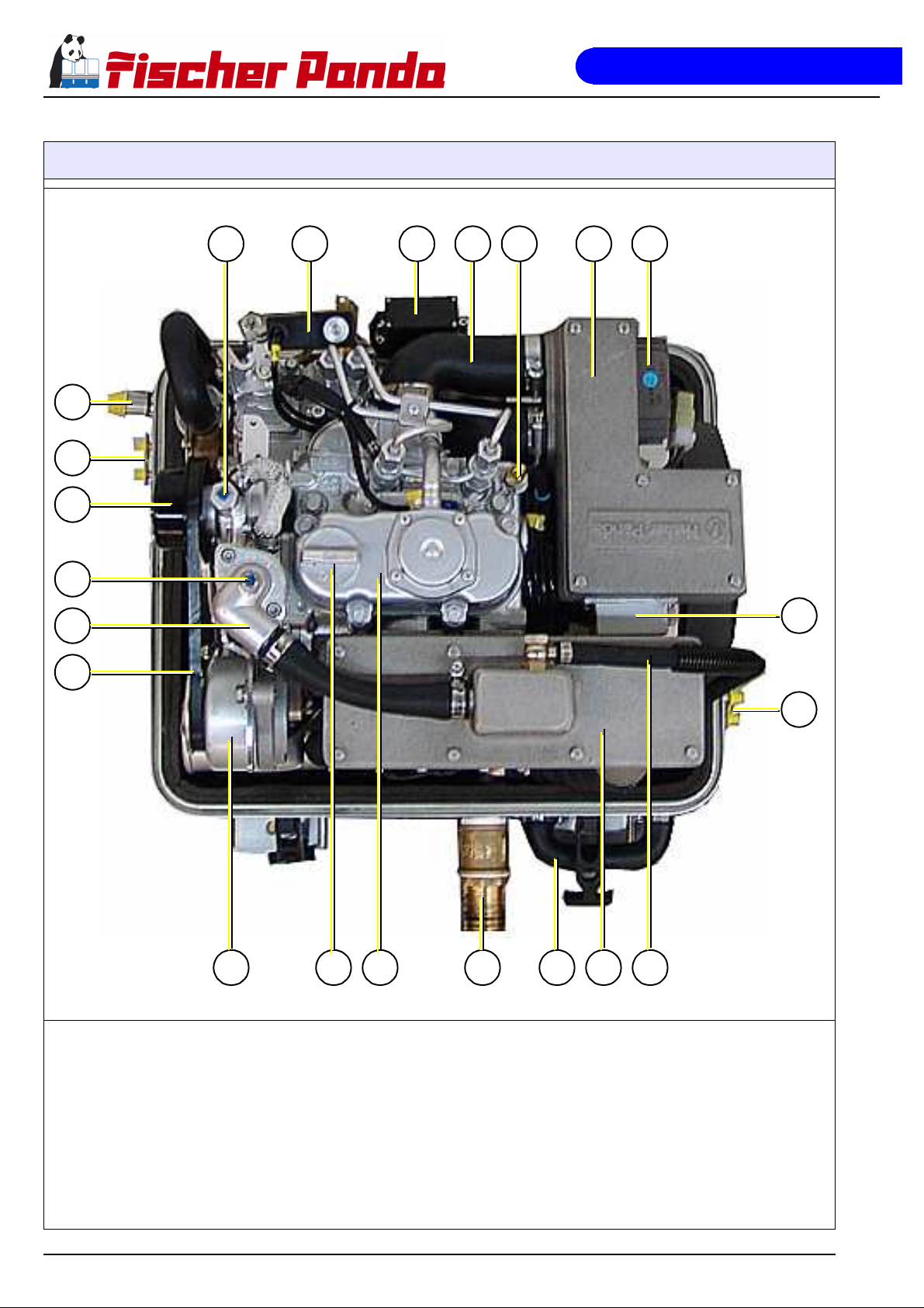
B.2.5 View from above
21
07 08 09 10 11 12
20 19 18 17 1622
01
02
03
04
05
06
13
14
15
01) Raw water intake
02) Fuel connections
03) Pulley for internal cooling water pump
04) Ventilation screw thermostat housing
05) Thermostat housing
06) V-belt
07) DC-alternator 12V
08) Oil filler neck with cap
09) Valve cover
10) Exhaust outlet
11) Connection for external ventilation valve
12) Watercooled exhaust elbow
13) Ventilation pipe to external expansion tank
14) Connections external expansion tank
15) Actuator power modul
16) Charge controller for DC-alternator
17) Air suction housing
18) Thermoswitch cylinder head
19) Suction hose, air suction housing - induction elbow
20) Actuator
21) Fuel solenoid valve
22) Ventilation screw internal cooling water pump
Panda 6000i PMS generator
Page 24 Panda 6000i generator_s01835_eng.R01 - Chapter: B: Panda 6000i PMS generator 16.1.09
Fig. B.2.5-1: View from above
Page 25
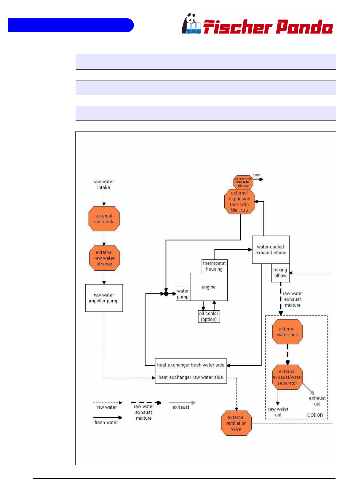
Panda 6000i PMS generator
B.3 Details of function units
B.3.1 Remote control panel - See Panda iControl manual
B.3.2 Components of the cooling system (raw- and freshwater)
Fig. B.3.2-1: Cooling system
16.1.09 Panda 6000i generator_s01835_eng.R01 - Chapter: B: Panda 6000i PMS generator - Description of the generator Page 25
Page 26
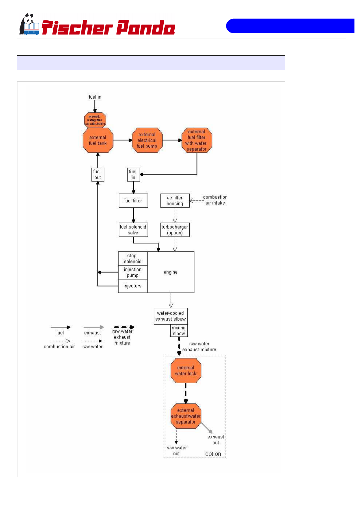
B.3.3 Components of the fuel, air intake and exhaust system
Panda 6000i PMS generator
Fig. B.3.3-1: Fuel, air intake and exhaust system
Page 26 Panda 6000i generator_s01835_eng.R01 - Chapter: B: Panda 6000i PMS generator - Description of the generator 16.1.09
Page 27
Panda 6000i PMS generator
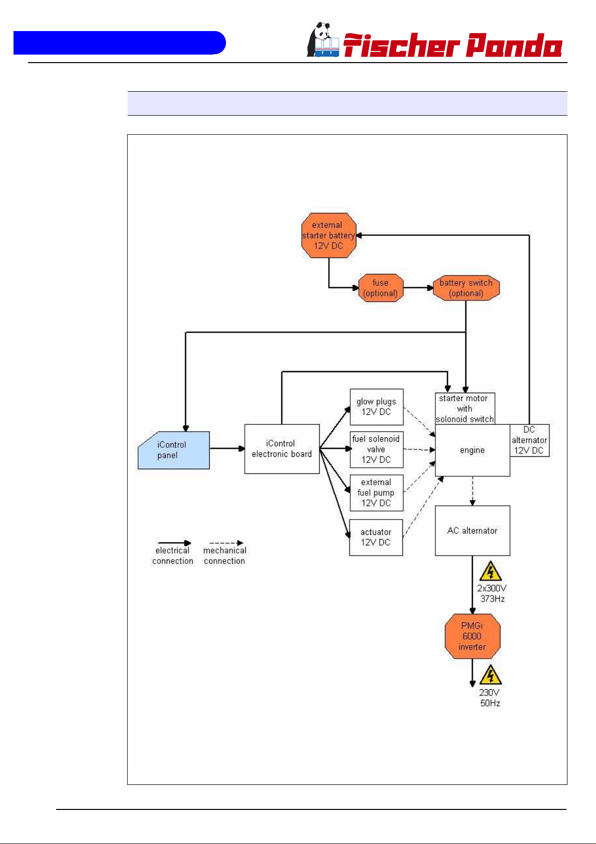
B.3.4 Components of the electrical system
Fig. B.3.4-1: Electrical system
16.1.09 Panda 6000i generator_s01835_eng.R01 - Chapter: B: Panda 6000i PMS generator - Description of the generator Page 27
Page 28
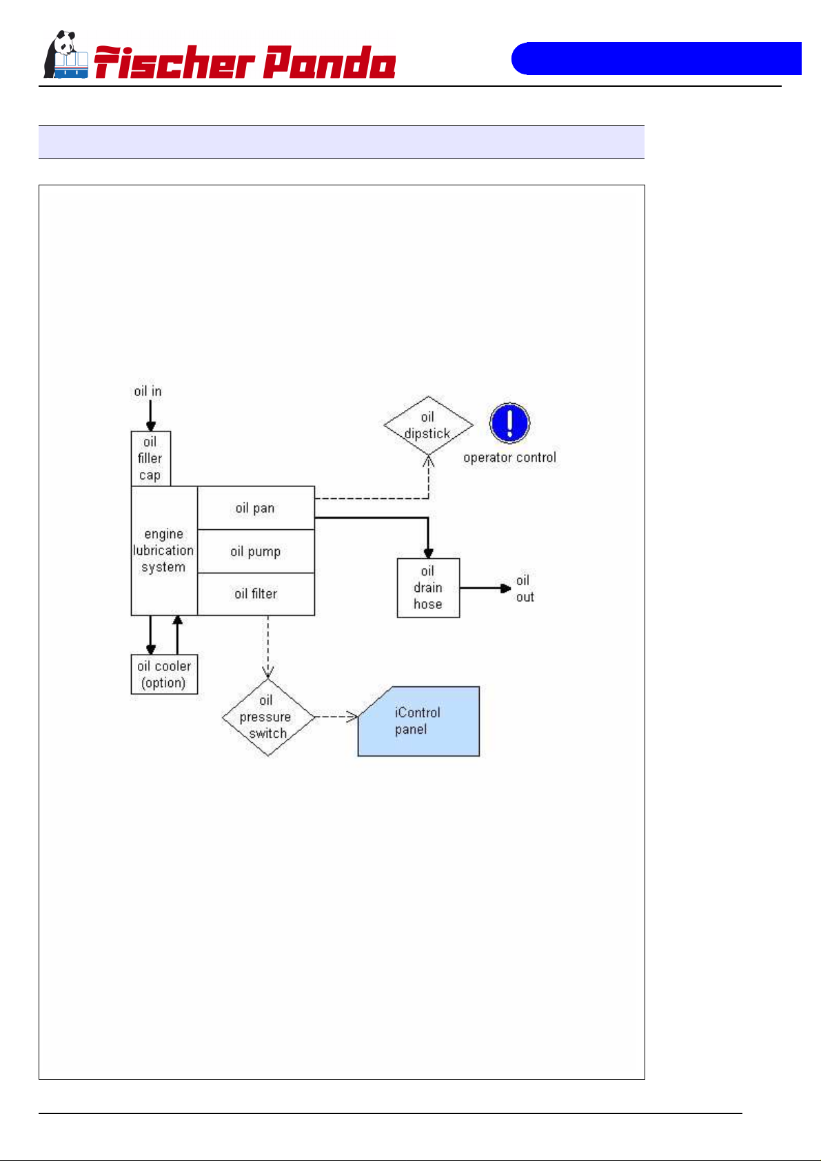
B.3.5 Components of the lubrication system
Panda 6000i PMS generator
Fig. B.3.5-1: Lubrication system
Page 28 Panda 6000i generator_s01835_eng.R01 - Chapter: B: Panda 6000i PMS generator - Description of the generator 16.1.09
Page 29
Panda 6000i PMS generator
B.3.6 Sensors and switches for operating surveillance
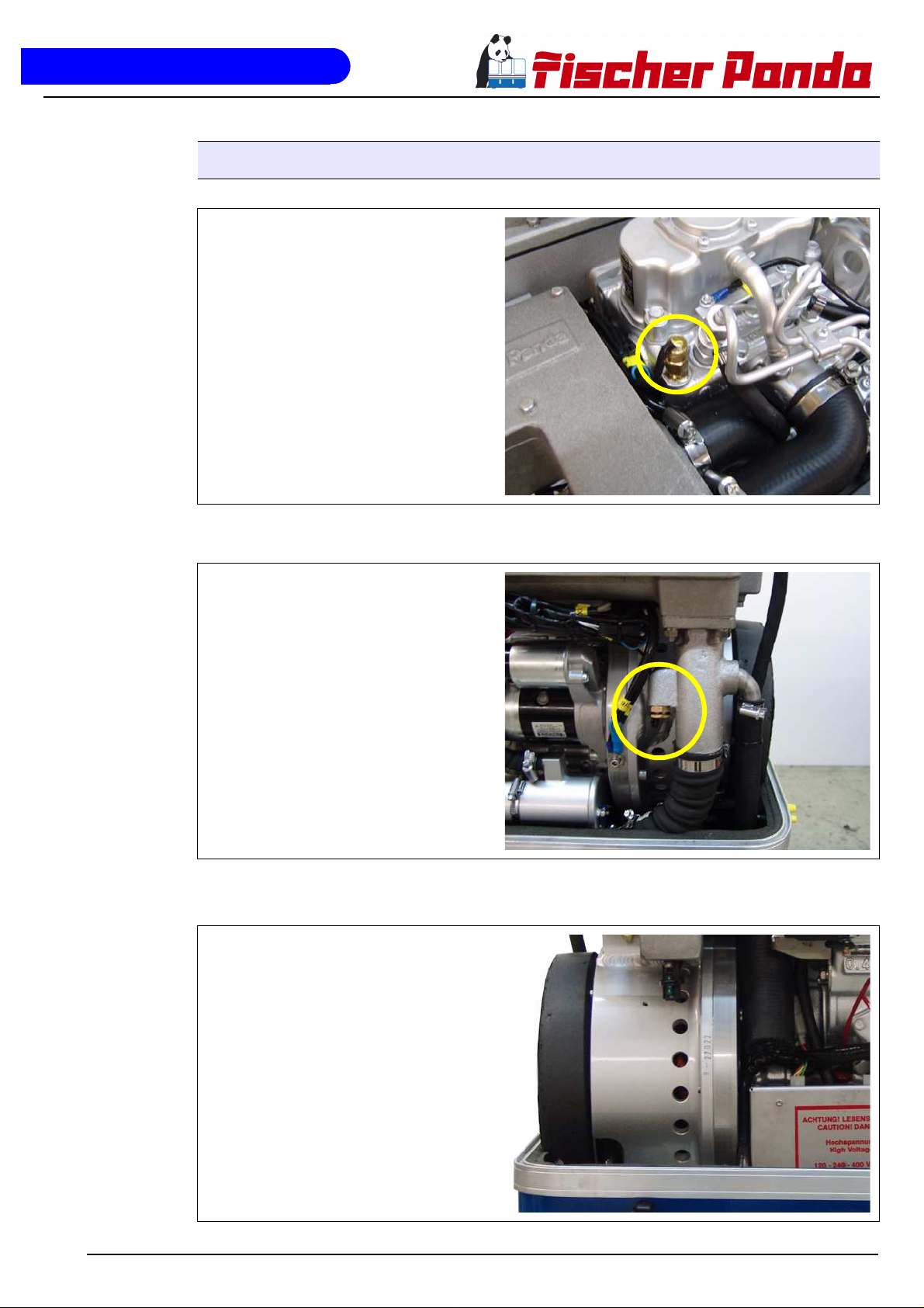
Thermo-switch at engine
The thermo-switch at the engine is used
for monitoring the engine temperature.
Fig. B.3.6-1: Thermo.switch at engine
Thermo-sensor at exhaust connection
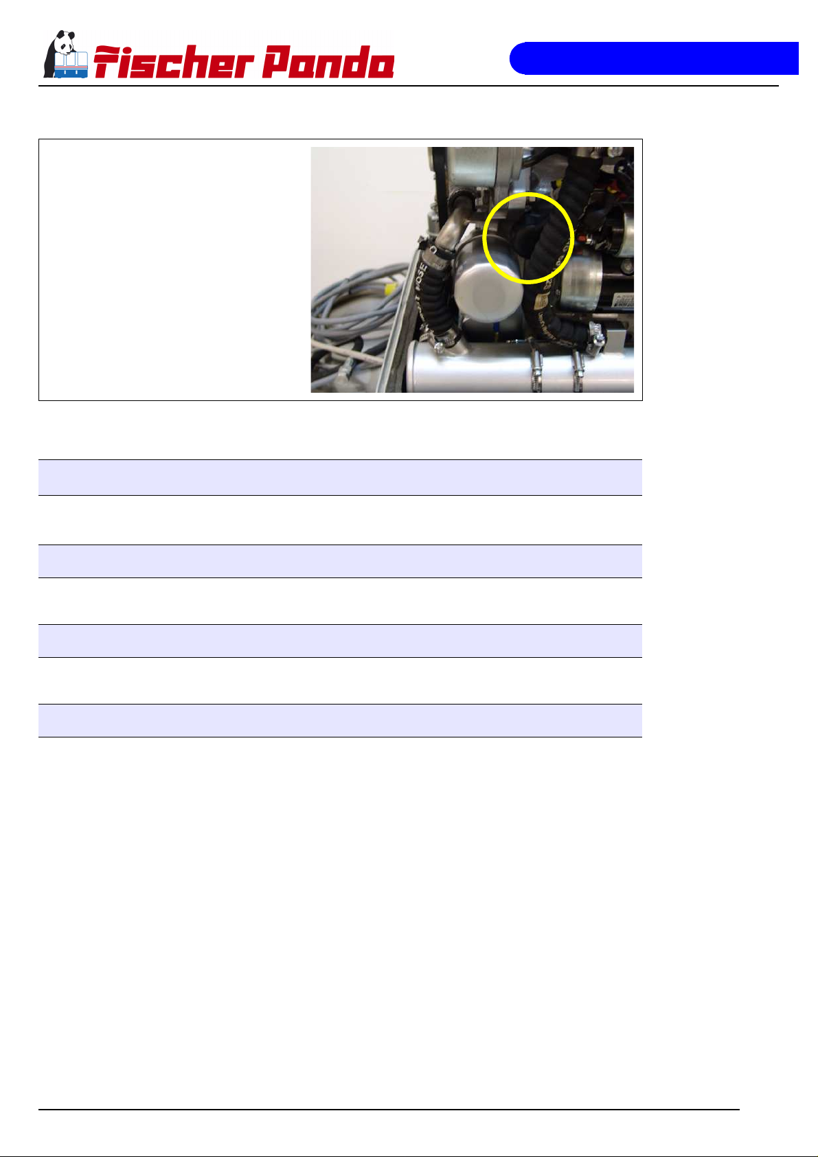
If the impeller pump drops out and deliveres no more raw water, the exhaust connection becomes extremely hot.
Fig. B.3.6-2: Thermo-sensor at exhaust connection
Thermo-switch coil
One thermo sensor is located in the stator
winding
Fig. B.3.6-3: Thermo-switch coil
16.1.09 Panda 6000i generator_s01835_eng.R01 - Chapter: B: Panda 6000i PMS generator - Description of the generator Page 29
Page 30
Oil pressure switch
In order to be able to monitore the lubricating oil system, an oil pressure switch is
built into the system.
Fig. B.3.6-4: Oil pressure switch
Panda 6000i PMS generator
B.4 Operation instructions - See Panda iControl panel manual
B.4.1 Daily routine checks before starting - See Panda iControl manual
B.4.2 Starting generator - See Panda iControl manual
B.4.3 Stopping the generator - See Panda iControl manual
Page 30 Panda 6000i generator_s01835_eng.R01 - Chapter: B: Panda 6000i PMS generator - Description of the generator 16.1.09
Page 31
Installation Instructions
C. Installation Instructions
C.1 Placement
Since Panda generators have extremely compact dimensions, they can be installed in tight locations. Attempts are sometimes made to install them in almost inaccessible places. Please consider
that even almost maintenance-free machinery must still remain accessible at least at the front
(drive belt, water pump) and the service-side (actuator, dipstick). Please also note that in spite of
the automatic oil-pressure sensor it is still essential that the oil level has to be checked regularly.
The generator should not be placed in the proximity of light walls or floors, which can have resonance vibrations because of airborne sounds. If this should be unavoidable, then it is recommended that this surface is lined with 1 mm lead foil, which will change the mass and the vibration
behaviour.
You should avoid fixing the generator on a slippery surface with little mass (i.e.). This acts as an
amplifier of airborne sounds in the most unreasonable case. An improvement can be achieved by
reinforcing these surfaces with ribs. In addition, the breakthroughs, which interrupt these surfaces, should be sawed off. The lining of the surrounding walls with a heavy layer (i.e lead) and
foam additionally improve the conditions.
The generator sucks its air from the surrounding engine room. Therefore it must be ensured that
sufficient ventilation openings are present, so that the generator cannot overheat.
High temperature of the intake air decline the power of the generator and increases the coolant
temperature. Air temperatures of more than 40°C red uce the power by 2% per temperature rise
of 5°C. In order to keep these effects as small as possible, the temperature in the engine room
should not be higher than 15°C in relation to the o utside temperature.
C.1.1 Advice for optimal sound insulation
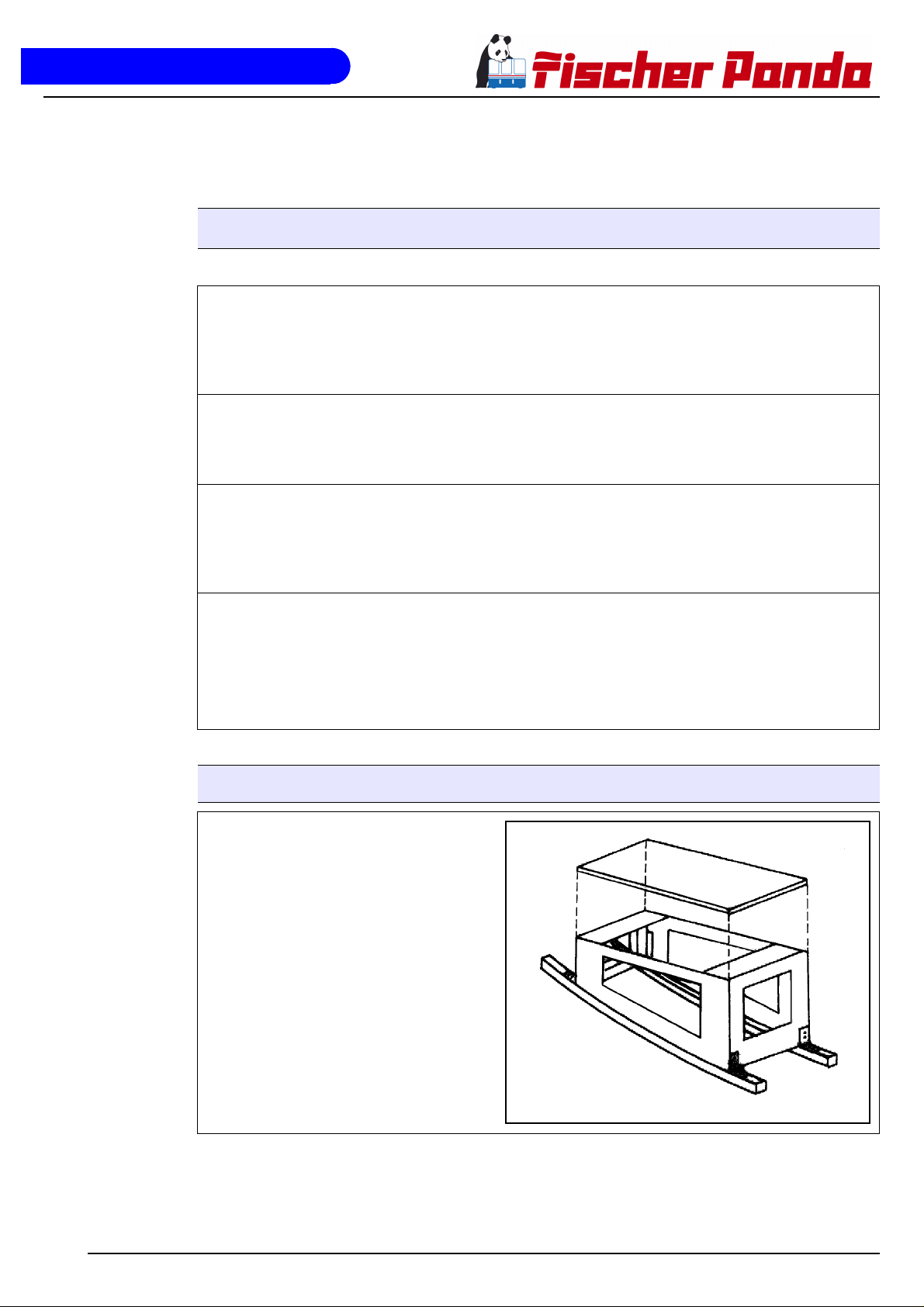
The convenient base consists of a stable
framework, on which the generator is
fastened by means of shock-mounts.
Since the aggregate is "free" downward,
the combustion air can be sucked in
unhindered.
In addition are void the vibrations, which
would arise with a closed soil.
Fig. C.1.1-1: Generator base
16.1.09 Panda_6000i_System_eng_s01835.book.R01 - Chapter C: Installation Instructions Page 31
Page 32
Installation Instructions
1
2
3
4
5
6
7 8
9
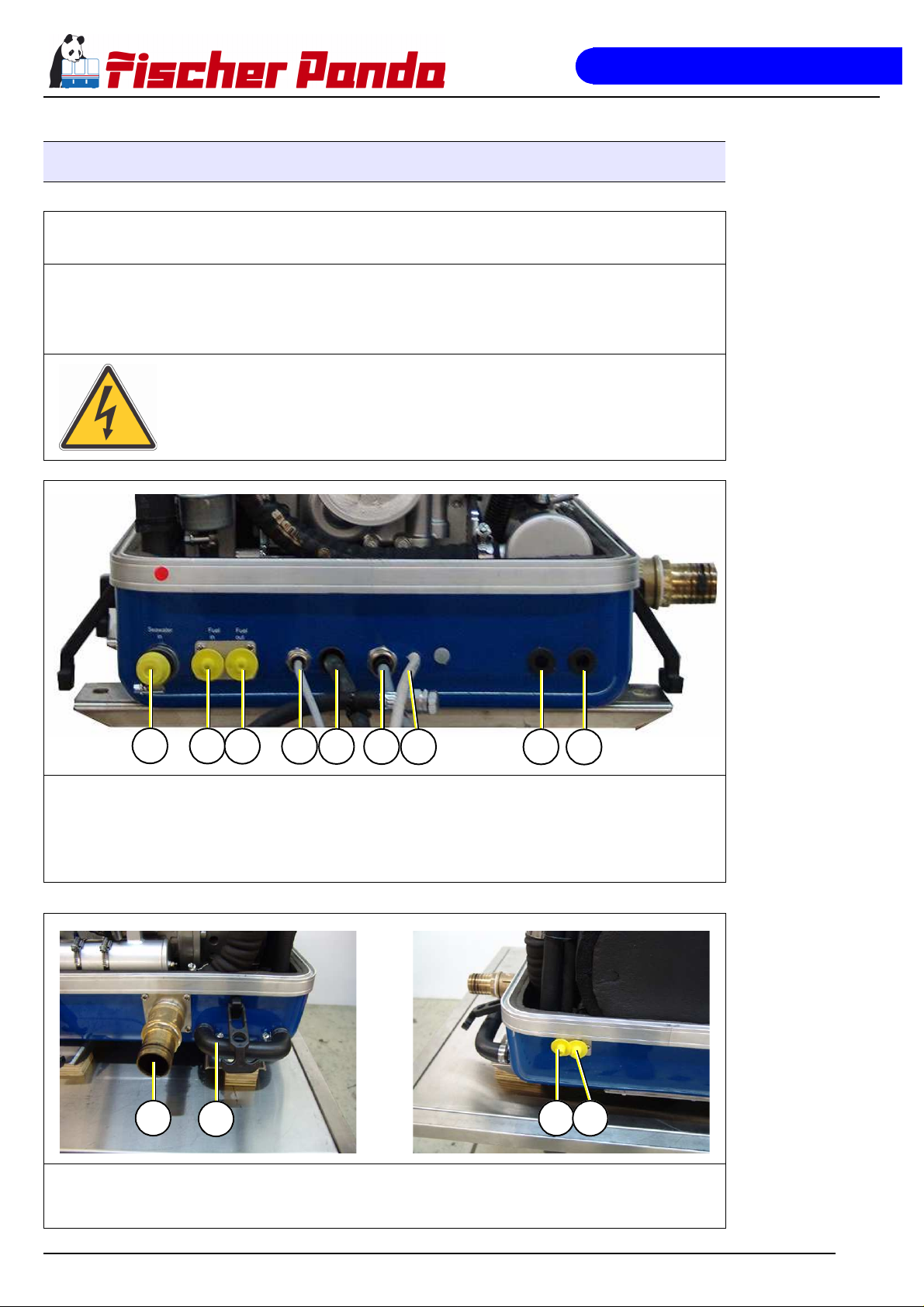
1. Raw water inltake
2. Fuel supply (in)
3. Fuel return line (out)
4. Cable for fuel pump
5. Motor oil drain hose
6. Cable for generator output AC out
7. Cable for iControl panel
8. Passage for starter battery cable (-)
9. Passage for starter battery cable (+)
1
2
3
4
1. Exhaust outlet
2. Connection external ventilation valve
3. Connection from external expansion tank
4. Connection to external expansion tank
C.2 Generator connections
Connect all electrical wires within the capsule tightly to the motor and the generator. This is also
the case for fuel lines and cooling water lines.
The electrical connections MUST be carried out according to the respective valid regulations. This also concerns used cable materials. The cable supplied is meant for laying "protected" (i.e. in pipe) at a temperature up to a max of. 70°C (160°F). The on-board circuit
must also be fitted with all essential fuses.
ATTENTION! Before working (installation) on the System read the section
„Safety Instructions“ in this Manual.
Fig. C.2-1: Generator connections
Page 32 Panda_6000i_System_eng_s01835.book.R01 - Chapter C: Installation Instructions 16.1.09
Fig. C.2-2: Generator connections
Page 33
Installation Instructions
C.3 Cooling system installation - Raw water
C.3.1 General information
The genset should have its own raw water (coolant water) inlet and should not be connected to
any other engine systems. Ensure that the following installation instructions are complied with:
For the avoidance of galvanic corrosion, refer to the chapter "Service instruction for
marine generators (corrosion protection)".
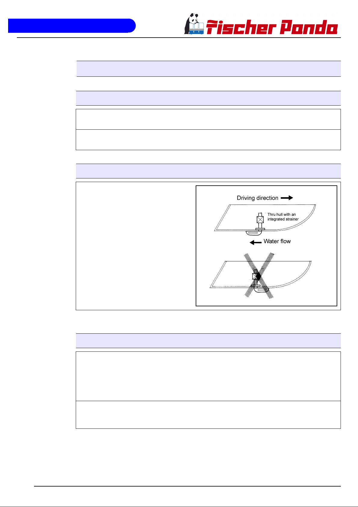
C.3.2 Installation of the thru hull fitting in yachts
It is good practice for yachts to use a thru
hull fitting with an integrated strainer. The
thru hull fitting (raw water intake) is often
mounted against the sailing direction to
induce more water intake for cooling.
For Panda generators, the thru hull inlet
should NOT point in the sailing direction!
When sailing at higher speeds more water
will be forced into the inlet than the pump
can handle and your generator will flood!
Fig. C.3.2-1: Position of the thru hull fitting
C.3.3 Quality of the raw water sucking in line
n order to keep the suction resistance in the line at a minimum, the raw water intake system (i.e.
sea cock, thru-hull fitting, inlet filter, etc.) must have an inner diameter of at least 1" (25 mm).
This applies also to installation components such as thru-hull fitting, sea cock, raw water filter etc.
The intake suction line should be kept as short as possible. Install the raw water inlet in close pro-
ximity to the genset.
After start-up the cooling water quantity must be measured (e.g. by catching at the
exhaust). The flow rate, as well as the necessary cross section of the cooling water pipe
see section F.2, “Technical data,” on page 74.
16.1.09 Panda_6000i_System_eng_s01835.book.R01 - Chapter C: Installation Instructions Page 33
Page 34
Installation Instructions
1
2
3
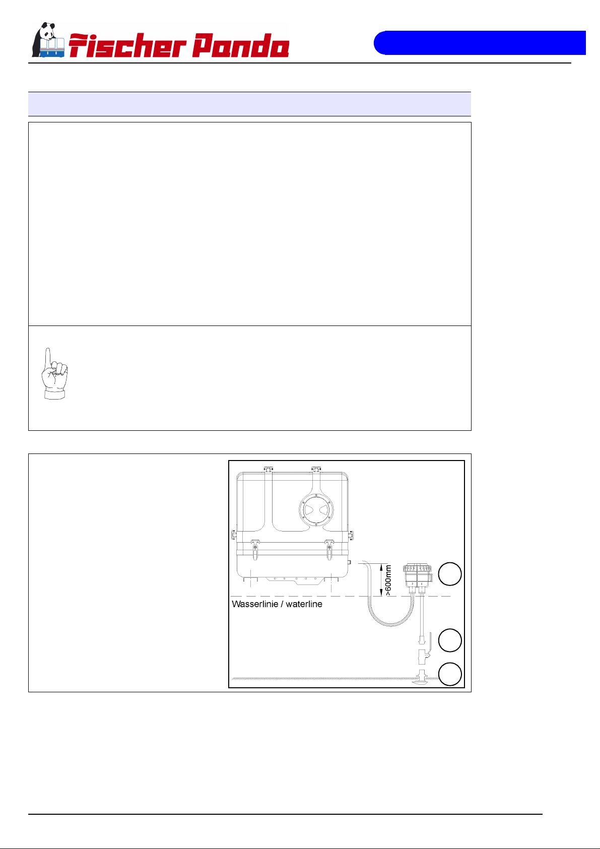
C.3.4 Generator installation above waterline
The Panda is equipped with a direct drive water intake pump mounted directly on the motor.
Since the intake pump is an impeller pump there are wearing parts which are likely to require
replacement after a period of time. Ensure that the genset is installed so that the intake pump can
be easily accessed. If this is not possible, an external intake pump could be installed in an easily
accessible location.
If the generator is installed above the waterline, it is possible that the impeller will wear out faster,
because after starting, the pump runs dry for some seconds.
The raw water hose should form a loop as near as possible to the raw water inlet of the generator
(see picture below). This ensures the pump only sucks in air for a short time. The impeller pump
will be lubricated by raw water and the impeller life span will be increased.
By the installation of a check valve in the raw water inlet line, which is under the waterline, this
problem can be restricted.
The impeller pump will remain intact longer, if an electrical booster pump is installed, and is strongly recommended in order to preserve the impeller pump.
NOTE:
Never change the impeller for many years, without exchanging the old pump. If the
sealing ring is defective within the pump, raw water runs into the sound cover of the
genset. A repair is then very expensive.
Replacement impeller and also a spare pump should always be on board. The old
pump can be sent back to Fischer Panda.
1. Raw water filter
2. Water cock
3. Thru hull
Make certain that the raw water filter lies
above the water level, otherwise with cleaning water can penetrate by the thru hull.
An external pre-pump can relieve the
impeller.
An external pre-pump can relieve the
impeller.
Fig. C.3.4-1: Raw water filter
Page 34 Panda_6000i_System_eng_s01835.book.R01 - Chapter C: Installation Instructions 16.1.09
Page 35
Installation Instructions
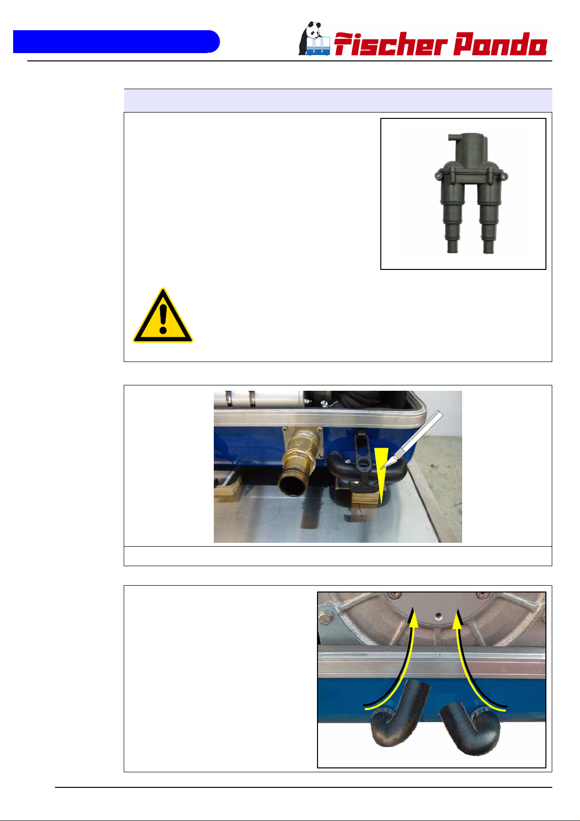
C.3.5 Generator installation below waterline
If the generator cannot be attached at least 600 mm
above the waterline, a vent valve must be installed at the
raw water line.
Possible heeling must be taken into consideration if
installed at the "mid-ship line"!
The water hose for the external vent valve is located at
the back of the sound insulated cover. This hose is split
in the middle and extended respectively at each end by
an additional hose and a connecting nipple. Both hose
ends must be led outside of the sound cover to one point,
if possible 600 mm over the waterline in the mid-ship line.
The valve is connected at the highest place to the two
hose ends.
Note: The vent valve must be installed directly behind the water pump.
If the water pump ceases, the valve spring ensures that air can enter and there-
fore, a syphon effect is avoided.
The de-aeration valve must be regularly controlled. If the water pump stops, the
valve spring ensures that air enters. It must be opened, cleaned and greased.
Fig. C.3.5-1: Vent valve
Cut the hose for the external vent valve....
Fig. C.1: Connection vent valve
...and bend it upwards.
Both hose ends must be led out outside of
the sound cover to one point, if possible
600 mm over the waterline at the midships line. The valve is connected at the
highest place with the two hose ends.
Fig. C.3.5-2: Connection vent valve
16.1.09 Panda_6000i_System_eng_s01835.book.R01 - Chapter C: Installation Instructions Page 35
Page 36
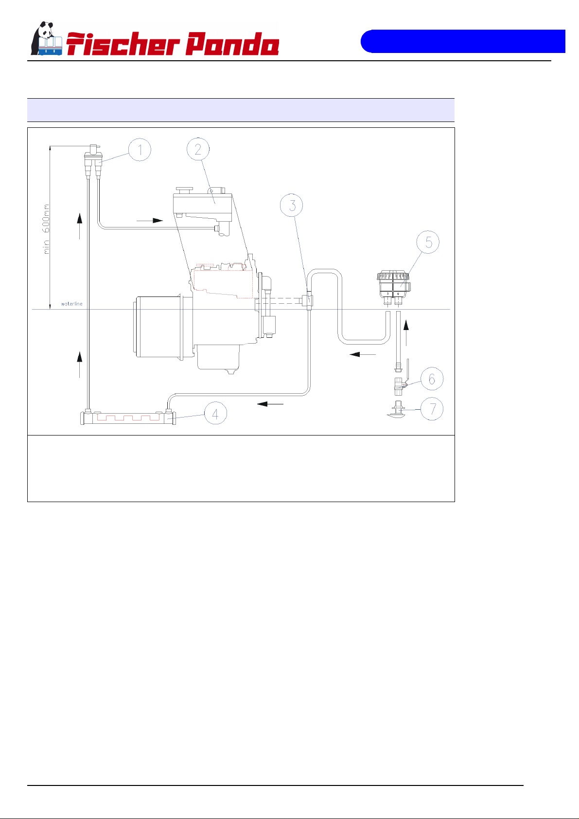
C.3.6 Indirect cooling of the genset housing (by the heat exchanger)
1. Ventilation valve
2. Exhaust elbow
3. Raw water pump (Raw water impeller pump)
4. Heat exchanger
5. Raw water filter
6. Water cock
7. Hull inlet
Installation Instructions
Fig. C.3.6-1: Installation scheme indirect cooling of the genset housing
Page 36 Panda_6000i_System_eng_s01835.book.R01 - Chapter C: Installation Instructions 16.1.09
Page 37
Installation Instructions
C.4 The freshwater coolant circuit
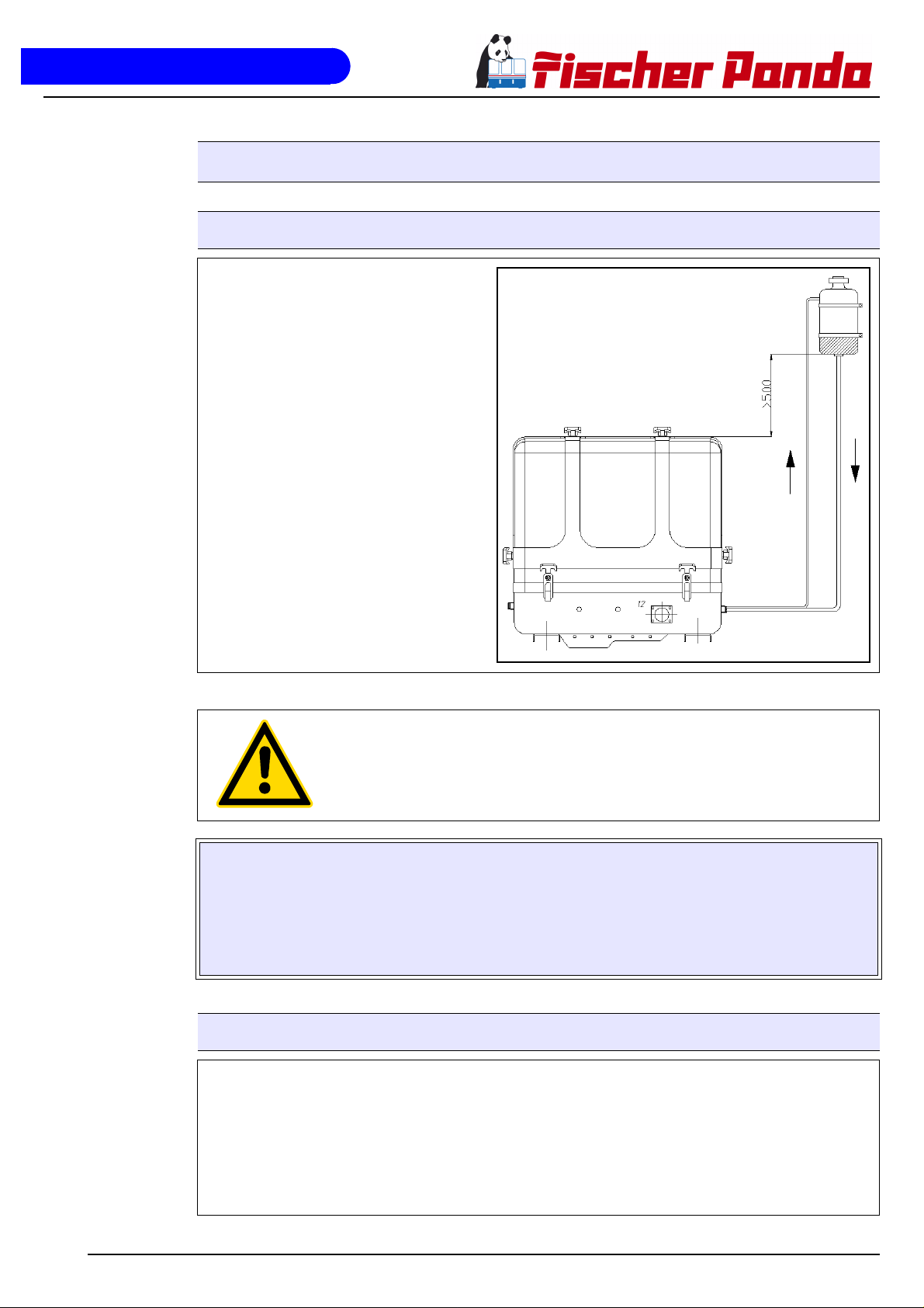
C.4.1 Position of the external cooling water expansion tank
Position of the external cooling water
expansion tank
The Panda generator is normally supplied with an additional, external cooling
water expansion tank. This tank must be
installed in such a way that its lower
edge is at least 500 mm more highly
arranged than the upper edge of the
sound cover.
If this 500 mm should be fallen below,
i.e. the cooling water expansion tank is
lower installed, very large problems can
occur with filling and ventilating. Extend
and displace the hose lines to the outside or possibly even up to the deck.
Fig. C.4.1-1: Position of the external cooling water expansion tank
ATTENTION! The external cooling water expansion tank may be filled
only up to the lower edge of the lower tension tape (see note "max") in
the maximum filling level in cold condition.
Anti-freeze
In the interest of safety, the freezing point of the closed circuit coolant should be checked on a
regular basis. Be sure that the coolant/antifreeze mixture is good for at least -15°C (5 ° F) and if i t
is possible that your genset experiences lower temperatures, for example during storage or transportation, then the entire cooling system should be drained and purged. To purge the cooling
system, compressed air at about 0.5 bar (7.5 psi) is sufficient.
C.4.2 Pressure test for controlling the cooling water circuit
Check if a temperature difference exists between cooling water in-flow and cooling water return
flow by use of the hand.
Feel the cooling water in-flow line at the internal cooling water pump.
Feel the cooling water return pipe either at the outlet of the water-cooled exhaust elbow union or
at the side, where this pipe exits at the heat exchanger.
The temperature difference between in-flow and return should be approx 10 degrees.
16.1.09 Panda_6000i_System_eng_s01835.book.R01 - Chapter C: Installation Instructions Page 37
Page 38
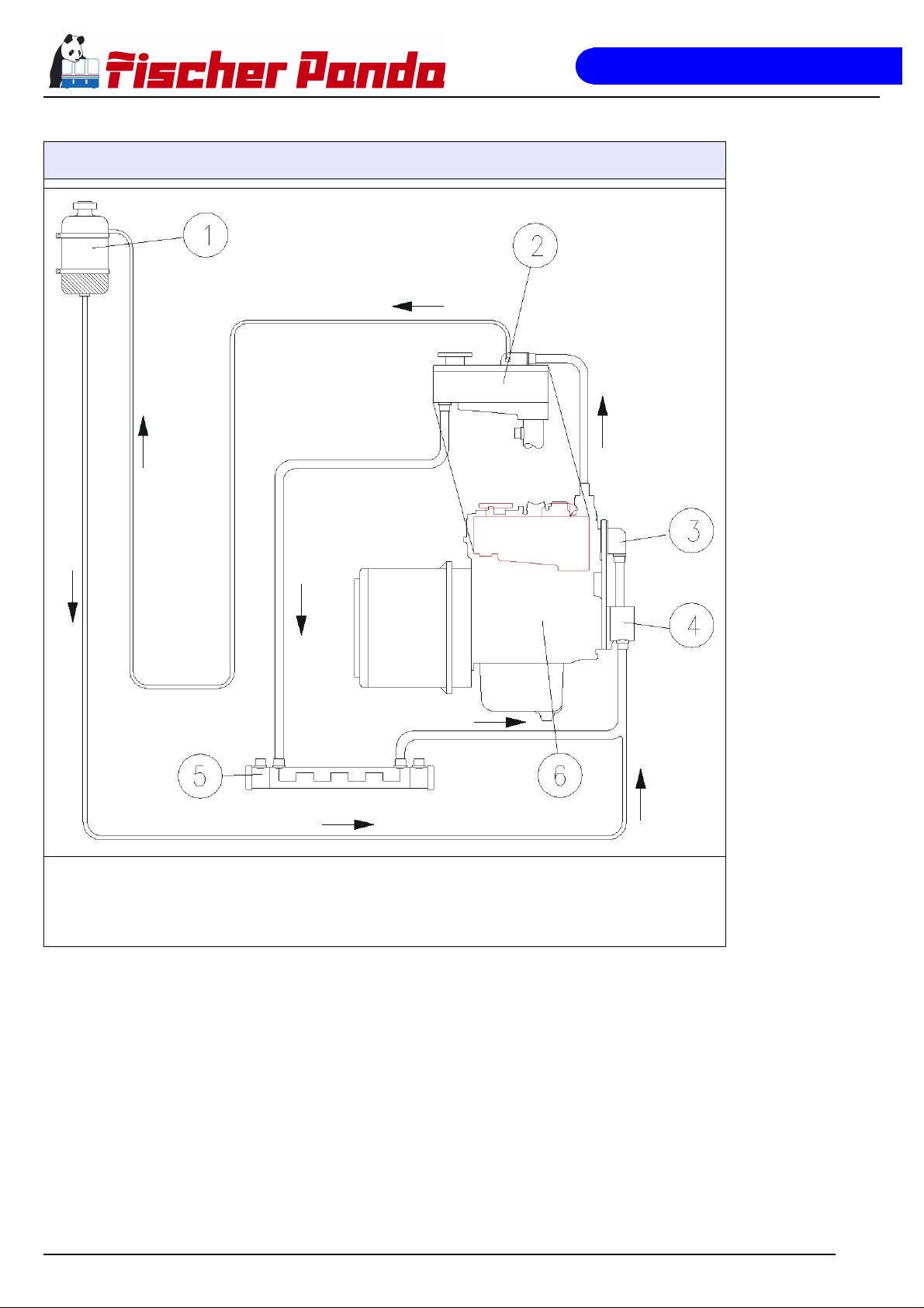
C.4.3 Scheme for freshwater circuit at two circuit cooling system
1. Expansion Tank
2. Exhaust Manifold
3. Thermostat Housing
4. Freshwater pump
5. Heat Exchanger
6. Engine
Installation Instructions
Fig. C.4.3-1: Scheme for freshwater circuit at two circuit cooling system
Page 38 Panda_6000i_System_eng_s01835.book.R01 - Chapter C: Installation Instructions 16.1.09
Page 39
Installation Instructions
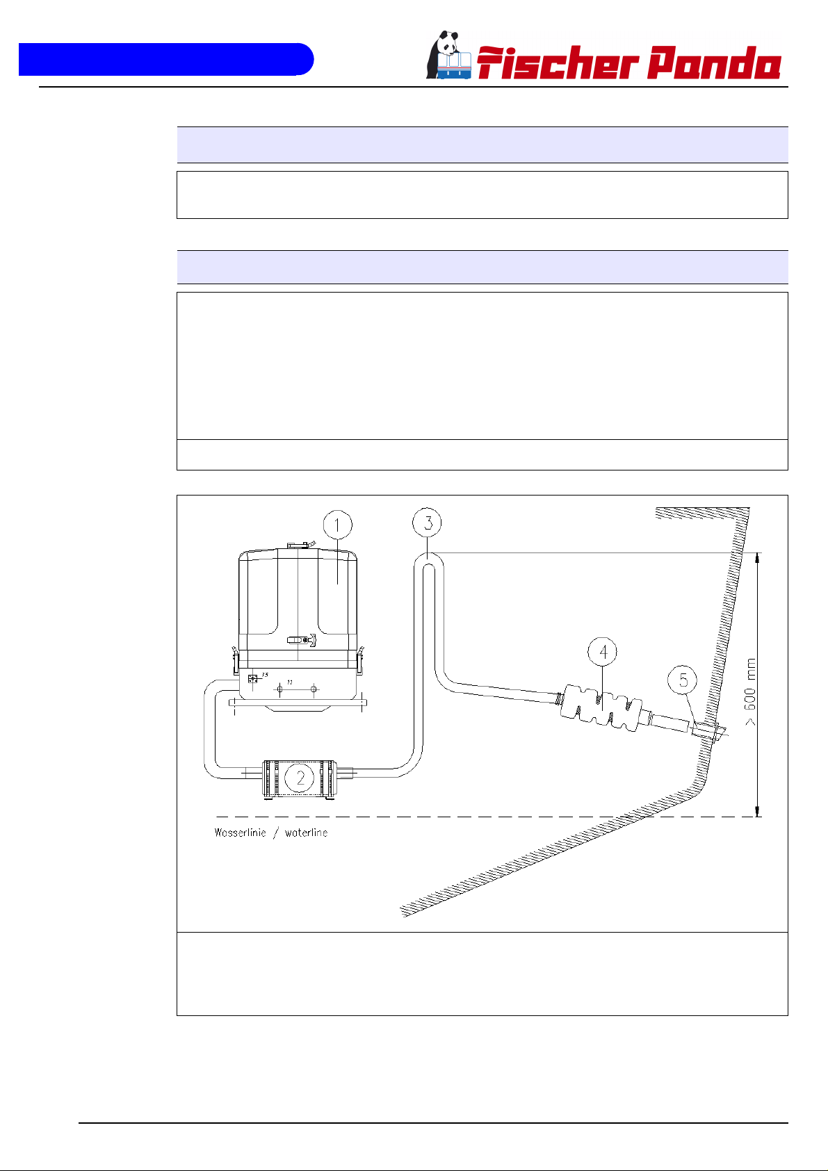
1. Generator
2. Water lock
3. Goose neck
4. Silencer
5. Hull outlet
C.5 Water-cooled exhaust system
By injecting the outlet raw water into the exhaust manifold, the exhaust gases are cooled and the
noise emissions from the exhaust system are reduced.
C.5.1 Installation of the standard exhaust system
The generator exhaust system must remain completely independent and separate from the
exhaust system of any other unit(s) on board. The exhaust hose has an inner diameter of 30 mm.
The water lock must be installed at the lowest point of the exhaust system. An optional noise
insulated water lock can also be installed. The exhaust hose descends from the capsule to the
water lock. Then the hose rises via the "goose neck" to the silencer (see drawing). The goose
neck must be vertical and sit preferably along the ship's keel centre line. The exhaust system
must be installed so that the back pressure inside the exhaust does not exceed 0.4 bar (6 psi)
and total length does not exceed 6 m (20 ft.).
Exhaust diameter see section F.2, “Technical data,” on page 74.
Fig. C.5.1-1: Installation scheme standard exhaust system
16.1.09 Panda_6000i_System_eng_s01835.book.R01 - Chapter C: Installation Instructions Page 39
Page 40
Installation Instructions
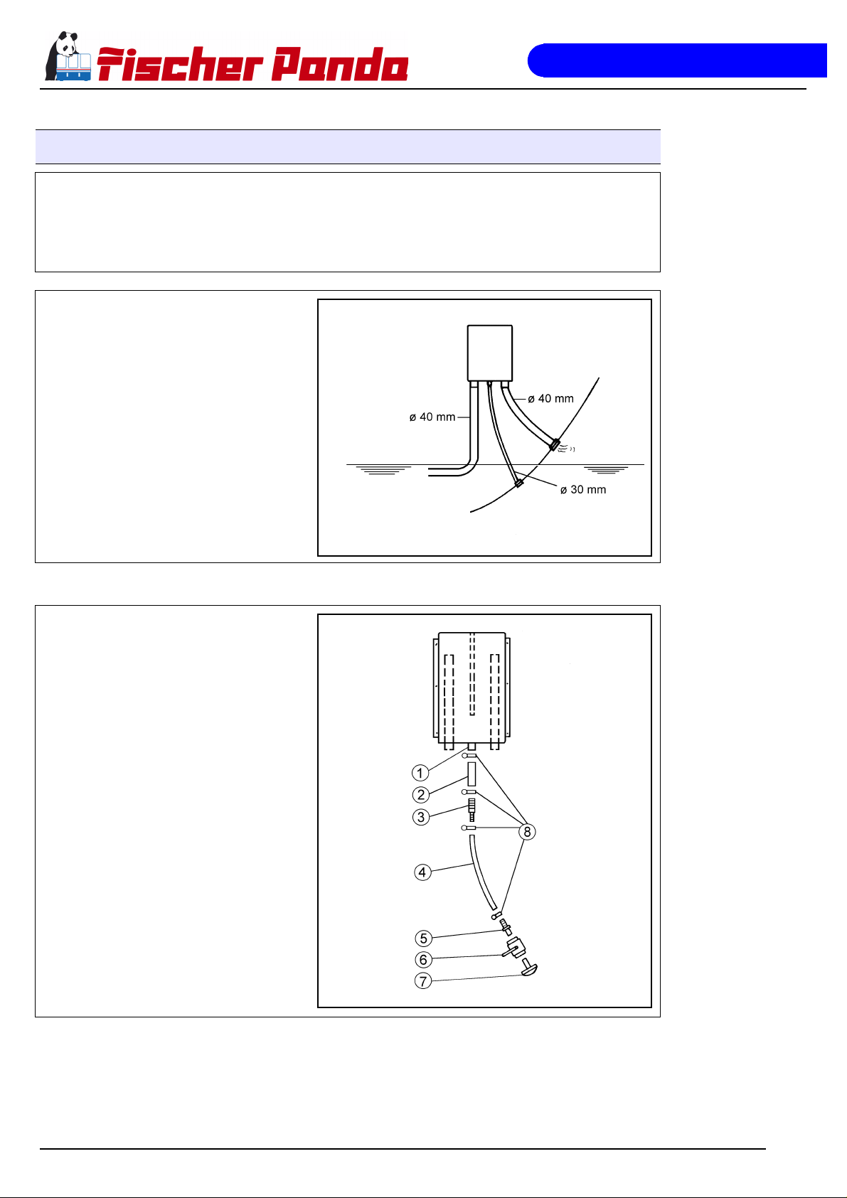
C.5.2 Exhaust / water separator
In order to reduce the noise level of the generator unit to a minimum, an optional exhaust outlet
muffler can be mounted next to the thru-hull fitting. Additionally there is a component at Fischer
Panda, which acts as both an "exhaust goose neck", and water separator. With this "exhaust/
water separator" the cooling water is derived over a separate pipe. The exhaust noises emanating from the exterior of the yacht are strongly decreased. Particularly the "water splash".
The water flow on the exhaust/water
separator unit has an inner diameter (ID)
of 30 mm. If the path from the water separator to the raw water outlet is very short,
the hose can be further reduced to 1"
(25mm) ID.
Fig. C.5.2-1: Water flow exhaust water separator
1. Raw water outlet ø 30mm
2. Hose connector ø 30mm
3. Reducer 30/20mm (if required)
4. Hose
5. Hose connector
6. Sea cock
7. Hull outlet
8. Hose Clips
Fig. C.5.2-2: Exhaust water separator
Page 40 Panda_6000i_System_eng_s01835.book.R01 - Chapter C: Installation Instructions 16.1.09
Page 41
Installation Instructions
1
5
6
2
3
4
1. Generator
2. Silencer / Water lock
3. Exhaust-Water-Separator
4. Silencer
5. Sea cock
6. Hull outlet
C.5.3 Installation exhaust-water-separator
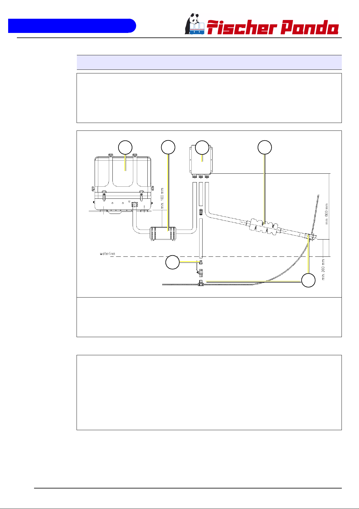
If the exhaust/water separator was sufficiently highly installed, a goose neck is no longer necessary. The exhaust/water separator fulfils the same function. If the "Super silent" exhaust system
were installed correctly, the generator will not disturb your boat neighbour. The exhaust noise
should be nearly inaudible. The best result is reached, if the hose line, which derive the cooling
water, is relocate on a short way "falling" directly to the outlet and this outlet is under the waterline.
16.1.09 Panda_6000i_System_eng_s01835.book.R01 - Chapter C: Installation Instructions Page 41
Fig. C.5.3-1: Installation scheme exhaust-water-separator
If the thru-hull exhaust outlet has to be mounted far from the generator, an exhaust-water separator must definitely be installed. The raw water from the separator must then run along the shortest
possible path is the thru-hull outlet. For such long exhaust routes, the exhaust hose diameter
should also be increased from NW40mm to NW50mm in order to reduce the back-pressure. The
exhaust may have a length of over 10m (32 ft.) if the exhaust hose diameter is increased to
50mm. An additional outlet exhaust muffler close to the hull outlet will help further to reduce noise
emissions.
The generator will not disturb your boat neighbours, if the "Super silent Exhaust System has been
correctly installed. The exhaust noise should be almost inaudible.
Page 42
Installation Instructions
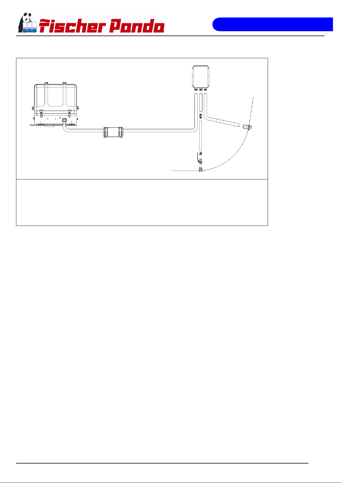
Example of an unfavourable installation:
- Water lock not far enough below the highest level of the generator
- Distance water lock to exhaust/water separator too large
Fig. C.5.3-2: Expample for an unfavourable installation
Page 42 Panda_6000i_System_eng_s01835.book.R01 - Chapter C: Installation Instructions 16.1.09
Page 43
Installation Instructions
1
2
3
4
5
8
7
6
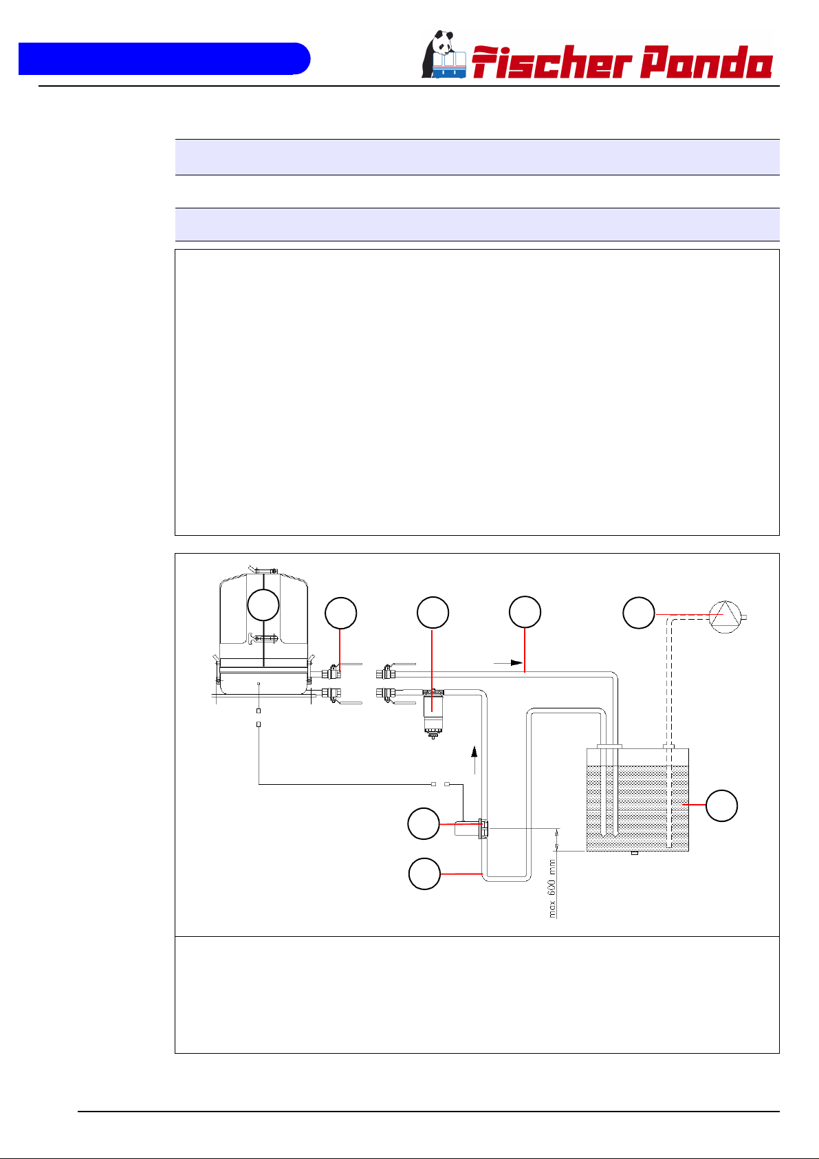
1. Generator
2. Fuel stopcock
3. Fuel filter with water separator
4. Fuel return
5. Condensation water suction pump (option)
6. Fuel tank
7. Fuel supply
8. Electrical fuel pump (12V-DC)
C.6 Installation of the fuel system
C.6.1 General references
Inside the generator capsule itself, there is the fuel filter installed (exception: Panda 4200 and
4500). Additional fuel filters (with water separator) must be mounted outside the capsule in easily
accessible places in the fuel lines between the tank intake fuel pump and the diesel motor's fuel
pump.
Generally forward and return fuel flow pipes must be mounted to the diesel tanks. Do not connect
the generator fuel supply lines with any other fuel lines of other diesel systems.
• The following items need to be installed:
• Fuel supply pump (12VDC)
• Pre-filter with water separator (not part of the delivery)
• Fine particle fuel filter
• Return fuel line to fuel tank (unpressurized)
The fuel supply pump should be mounted as close to the fuel tank as possible. The electric cable
for the fuel pump is already installed on the generator (length 5 m).
16.1.09 Panda_6000i_System_eng_s01835.book.R01 - Chapter C: Installation Instructions Page 43
Fig. C.6.1-1: Installation scheme fuel system
Page 44
C.6.2 The electrical fuel pump
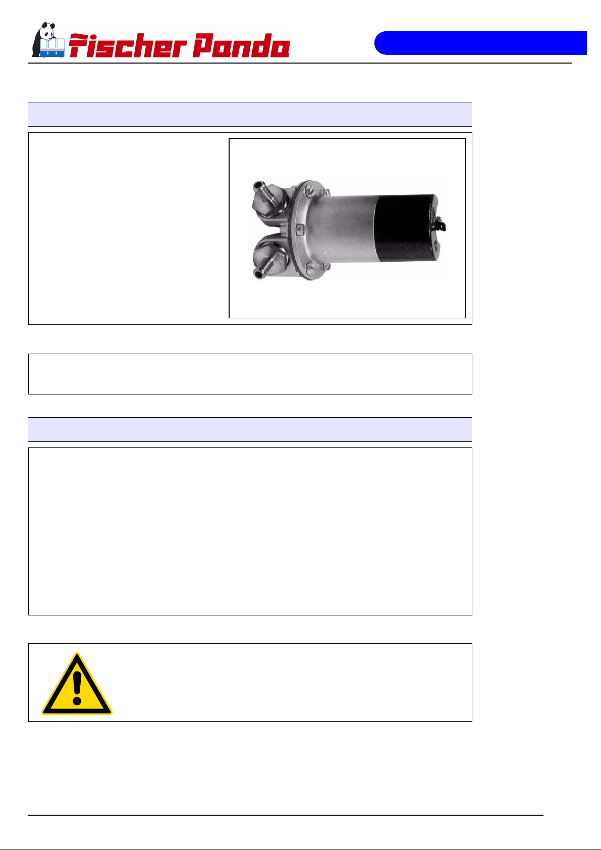
Electrical Fuel Pump
With the Panda generator is usually supplied an external, electrical fuel pump (12 V
DC). The fuel pump must be installed
close at the fuel tank. The electrical connections are pre-loaded at the generator
with the lead planned.
Fig. C.6.2-1: Electrical fuel pump
Installation Instructions
• Suction hight of the pump: max. 1,2 m at 02, bar
• Diameter of fuel lines: section F.2, “Technical data,” on page 74.
C.6.3 Connection of the fuel lines at the tank
Lead the return fuel pipe connected to the day tank to the floor
The return pipe connected to the tank must be dropped to the same depth as the suction pipe, if
the generator is mounted higher than the tank, in order to prevent fuel running back into the tank
after the motor has been switched off, which can lead to enormous problems, if the generator is
switched off for a long period.
Non-return Valve in the Suction Pipe
A non-return valve must be fitted to the suction pipe, which prevents the fuel flowing back after
the generator has been switched off, if it is not possible to use the return flow pipe as a submerge
pipe placed in the tank. The instructions "Bleeding Air from the Fuel System" must be read after
initial operation or after it has stood still for a long period, in order to preserve the starter battery.
ATTENTION! Non-return valve for the Fuel Return Pipe
If the fuel tank should be installed over the level of the generator (e.g. daily
tank), then a non-return valve must be installed into the fuel return pipe to
guarantee that through the return pipe no fuel is led into the injection pump.
Page 44 Panda_6000i_System_eng_s01835.book.R01 - Chapter C: Installation Instructions 16.1.09
Page 45
Installation Instructions
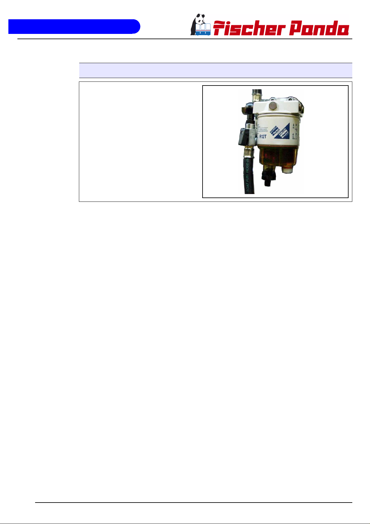
C.6.4 Position of the pre-filter with water separator
Additionally to the standard fine filter a
pre-filter with water separator must be
installed outside of the sound insulation
capsule in the fuel system line (not included in the delivery).
Fig. C.6.4-1: Pre-Filter with water separator
16.1.09 Panda_6000i_System_eng_s01835.book.R01 - Chapter C: Installation Instructions Page 45
Page 46
Installation Instructions
C.7 Generator 12VDC system installation
The Panda generators have their own dynamo to charge a 12V starter battery.
It is recommended to install an additional starter battery for the generator.
The generator is then independent from the remaining battery set. This enables you to start the
genset at any time with its own starter battery even if the other batteries are discharged. A further
advantage of a separate starter battery is that it isolates the generator's electric system from the
rest of the boat's DC system, i.e. minus pole (-) is not connected electrically to Earth/Ground.
The generator is then Earth/Ground free.
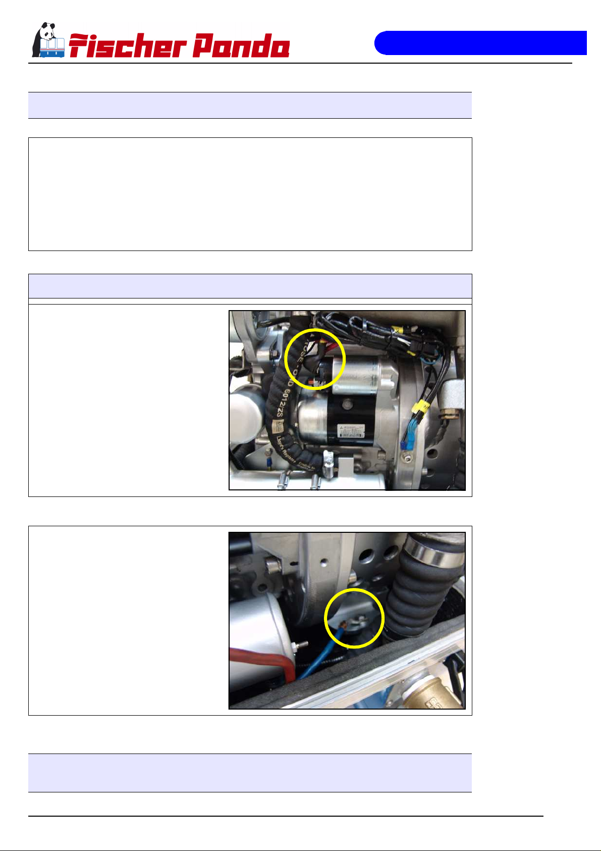
C.7.1 Connection of the 12V starter battery
The positive (+) battery cable is connected directly to the solenoid switch of the
starter.
Fig. C.7.1-1: Positive battery cable
The negative (-) battery cable is connected to the generator foot.
Note! The battery negative pole may not
be connected with the boat ground or with
the protective grounding of the installation!
Fig. C.7.1-2: Negative battery cable
C.7.2 Connection of the remote control panel - See Panda iControl panel manual
Page 46 Panda_6000i_System_eng_s01835.book.R01 - Chapter C: Installation Instructions 16.1.09
Page 47
Installation Instructions
1
2
3
4
5
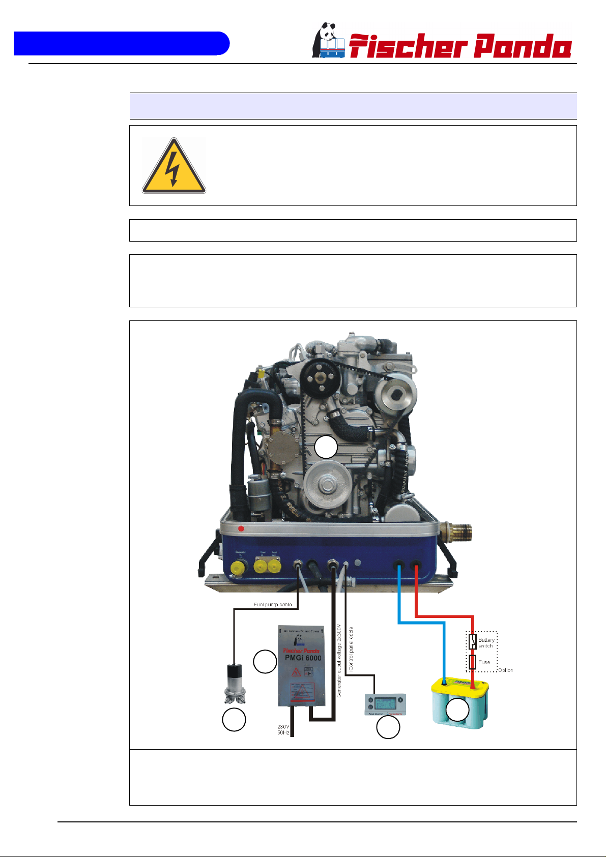
1. Generator
2. Electrical fuel pump 12VDC
3. PMGi 6000 inverter
4. iControl panel
5. Starter battery 12VDC
C.8 Generator AC system installation
All electrical safety installations have to be made on board.
Required cable cross-sections
The following recommended electrical cable dimensions (cross sections) are the minimum required sizes for a safe installation. (see section F.2, “Technical data,” on page 74)
ATTENTION! Before the electrical system is installed, READ the SAFETY
INSTRUCTIONS of this manual FIRST! Be sure that all electrical installations
(including all safety systems) comply with all required regulations of the regional authorities. This includes lightening conductor, personal protection switch
etc.
16.1.09 Panda_6000i_System_eng_s01835.book.R01 - Chapter C: Installation Instructions Page 47
Fig. C.2: Electrical installation - example
Page 48

C.8.1 Installation PMGi inverter - See separat PMGi 6000 inverter manual
Installation Instructions
Page 48 Panda_6000i_System_eng_s01835.book.R01 - Chapter C: Installation Instructions 16.1.09
Page 49
Generator Failure
D. Generator Failure
ATTENTION! Before working on the System read the section , “Safety Precautions,” on
page 15.
D.1 Tools and measuring instruments
In order to be able to manage disturbances while driving, following tools and measuring
instruments should belong to the equipment on board:
• Multimeter for voltage (AC), frequency and resistance
• Measuring instrument for inductance
• Measuring instrument for capacity
• Current absorbing clamps
• Thermometer (ideal is a infrared thermometer)
• Pressure device (pincer) für coolant circuit
D.2 Overloading the generator
Please ensure that the genset is not overloaded. Overloading occurs when the electrical load
(demand) induces a load torque in the generator which is higher than that which the diesel drive
motor can provide. Overloading causes the engine to run rough, burn oil, creates excessive
exhaust (environmentally unfriendly) and even to stall. Extra caution should be practised with
multi-power units (single and 3-phase current generation) to avoid overloading the diesel drive
engine.
The generator should only be loaded at the peak rated power for short periods only! A high peak
current is required to start many electrical devices, especially electric motors and compressors
(from a still stand state).
In order to prolong the genset´s life expectancy, the nominal electrical demand on the system
should not be more than 70% of the rated genset peak load.
Keep PEAK LOADING demand in mind when switching on electrical devices (esp. fridge compressors, electric motors, battery chargers, kettles, etc.) which are fed by the generator. Careful
"powering up" (gradual loading) of the electrical demand on the generator will help prolong the life
of your genset! The genset can be run for several hours at partial load (i.e. 2/3 of rated power),
however it is not advised that it is run for more than 2-3 hours at full load. The Panda is designed
so as not to overheat even under extreme conditions. Note: The exhaust gas will become sooty
during peak-load operation.
Effects of Short Circuiting and Overloading on the Generator
The generator cannot be damaged by short circuiting or overloading. Short circuiting and overloading suppress the magnetic excitation of the generator, thus, no current is generated and the
voltage will collapse. This condition is immediately offset once the short-circuit has been eliminated and/or the electrical overload removed.
16.1.09 Panda 6000i generator_s01835_eng.R01 - Chapter D: Generator Failure Page 49
Page 50
D.2.1 Low generator-output voltage
ATTENTION! Before working on the System read the section “Safety Precautions” on
Page 15.
If the produced alternating voltage is too low, switch the load off, in order to relieve the generator.
Mostly the problem already solved. If the output voltage is still too low, even if all load is switched
off, the generator runs without load, you can assume one or more condensers are defective.
D.3 Starting problems
D.3.1 Fuel solenoid valve
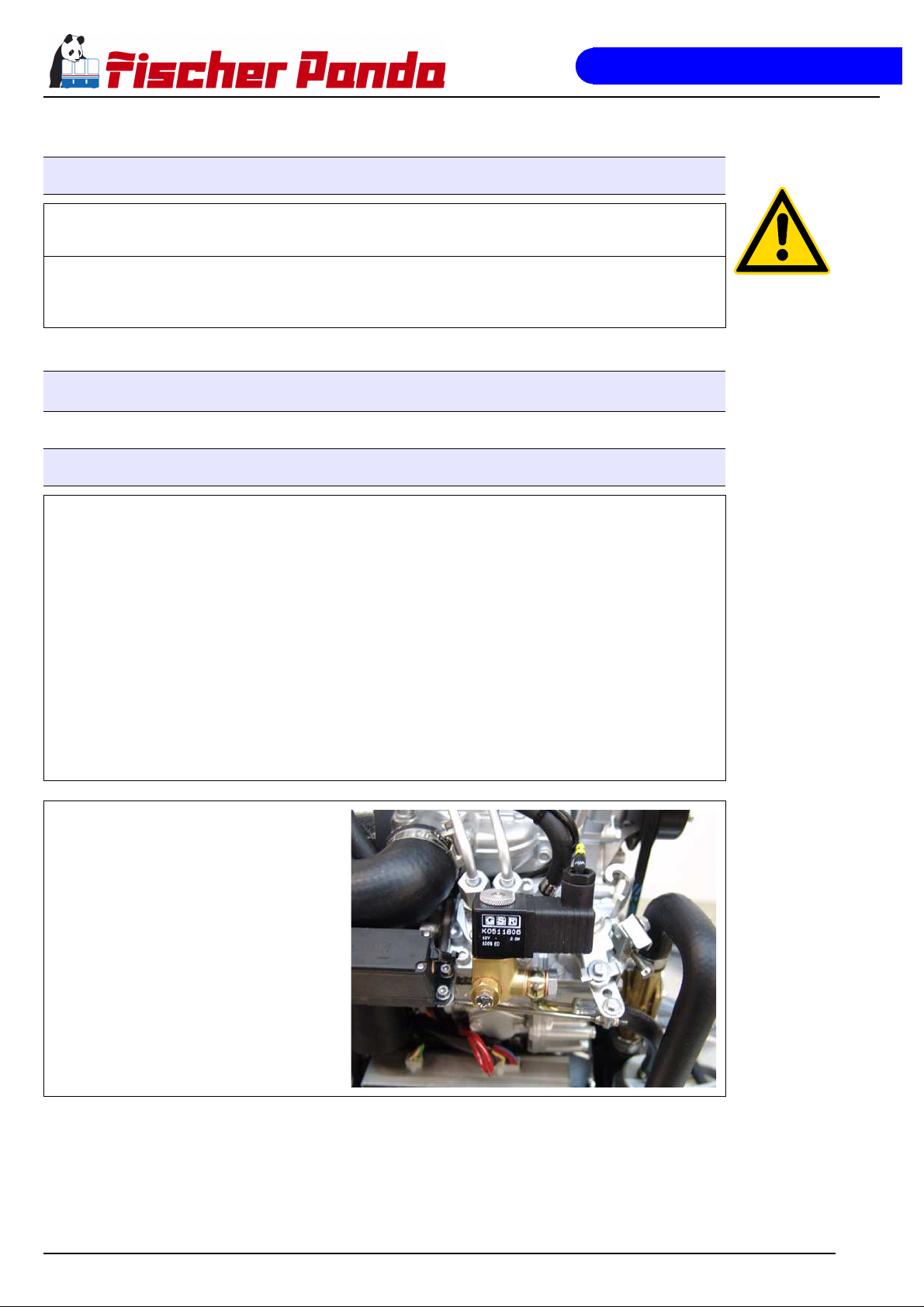
For start problems the possibility of an error exists with the solenoid for engine stop or fuel solenoid valve, which both effect affect simultaneous on the fuel system.
Generator Failure
The fuel solenoid valve is located in front of the injection pump. It opens automatically, if the
"START"-button is pressed on the remote control panel. The solenoid valve is CLOSED when the
generator main power is switched "OFF". For this reason, it requires a few seconds before the
motor comes to a full halt.
If the generator fails to start, runs rough, does not reach the proper RPM, or does not stop properly, the first item to suspect in most cases is the fuel solenoid valve and should be inspected
first.
A check of the fuel solenoid valve by removing the plug from the fuel solenoid valve for a short
period whilst in operation (first remove the small retention screw) and replace it immediately. The
motor should "react immediately" by revving high.If the motor does not react sharply to the reconnection of the solenoid wire, it is a sign that the solenoid valve could be faulty.
Fuel solenoid valve
Fig. D.3.1-1: Fuel solenoid valve
Page 50 Panda 6000i generator_s01835_eng.R01 - Chapter D: Generator Failure 16.1.09
Page 51
Generator Failure
1
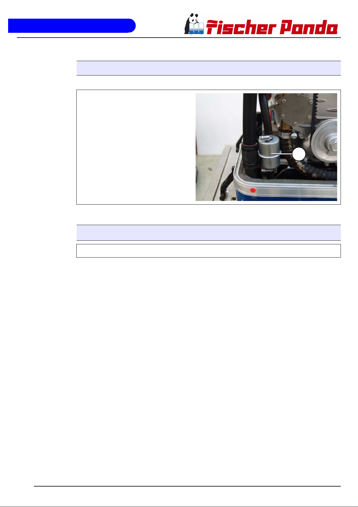
D.3.2 Dirty fuel filter
If the fuel filter is dirty change the filter element.
For replacing the filter element see
section C.3.1, “Replacing fuel filter” on
page 79.
1. Fuel filter element
Fig. D.3.2-1: Fuel filter
D.4 Troubleshooting table
For troubleshooting see section F.1, “Troubleshooting” on page 71.
16.1.09 Panda 6000i generator_s01835_eng.R01 - Chapter D: Generator Failure Page 51
Page 52

Generator Failure
Intentionally Blank
Page 52 Panda 6000i generator_s01835_eng.R01 - Chapter D: Generator Failure 16.1.09
Page 53
Maintenance Instructions
E. Maintenance Instructions
ATTENTION! Before working on the System read the section , “Safety Precautions,” on
Page 15.
E.1 General maintenance instructions
E.1.1 Checks before starting
• Oil level
• Cooling system leaks
• Visual check for any changes, leaks oil drain system, v-belt, cable connections, hose clips, air
filter, fuel lines
Once a month
• Grease/oil the servo motor - Trapezoid thread-Spindle
Maintenance invervals see „Genrael informations for PMS-Generators“.
E.1.2 Check of hoses and rubber parts in the sound insulated capsule
Check all hoses and hose connections for good condition. The rubber hoses are very sensitive to
environmental influences. They wear quickly in an environment of dry air, oil and fuel vapours,
and high temperatures. The hoses must be checked regularly for elasticity. There are operating
situations, when hoses must be renewed once a year.
Additionally to usual tasks of maintenance (oil level check, oil filter control etc.) further maintenance activities are to be accomplished for marine generators, such as control of the sacrificial
anode (cooling water connection block) and the front seal cover at the generator.
E.2 Oil change intervals
The first oil change is to be accomplished after a period of operation from 35 to 50 hours. Afterwards the oil is to be changed after 150 hours. For this the oil SAE30 for temperatures over 20°C
and SAE20 for temperatures between 5°C and 20°C is to be used. At temperatures under 5°C oil
of the viscosity SAE10W or 10W-30 is prescribed.
For fill-up capacity see section F.2, “Technical data,” on Page 74.
16.1.09 Panda_6000i_System_eng_s01835.book.R01 - Chapter E: Maintenance Instructions Page 53
Page 54
E.2.1 Execution of an oil change
17
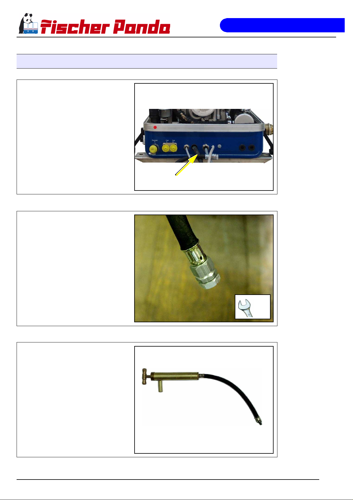
Oil drain hose
For the oil change an oil drain hose is fed
through the sound insulation capsule.
Fig. E.2.1-1: Oil drain hose
Maintenance Instructions
Oil Drain Screw
The oil can be discharged by opening the
oil drain screw. For countering use a
second wrench.
Fig. E.2.1-2: Oiil drain screw
Oil Drain Pump
If drainage of the oil is not possible, we
recommend the employment of a hand
pump, which can be attached to the oil
drain hose.
Close the oil drain screw.
Fig. E.2.1-3: Oil drain pump
Page 54 Panda_6000i_System_eng_s01835.book.R01 - Chapter E: Maintenance Instructions 16.1.09
Page 55
Maintenance Instructions
Oil Filter Change
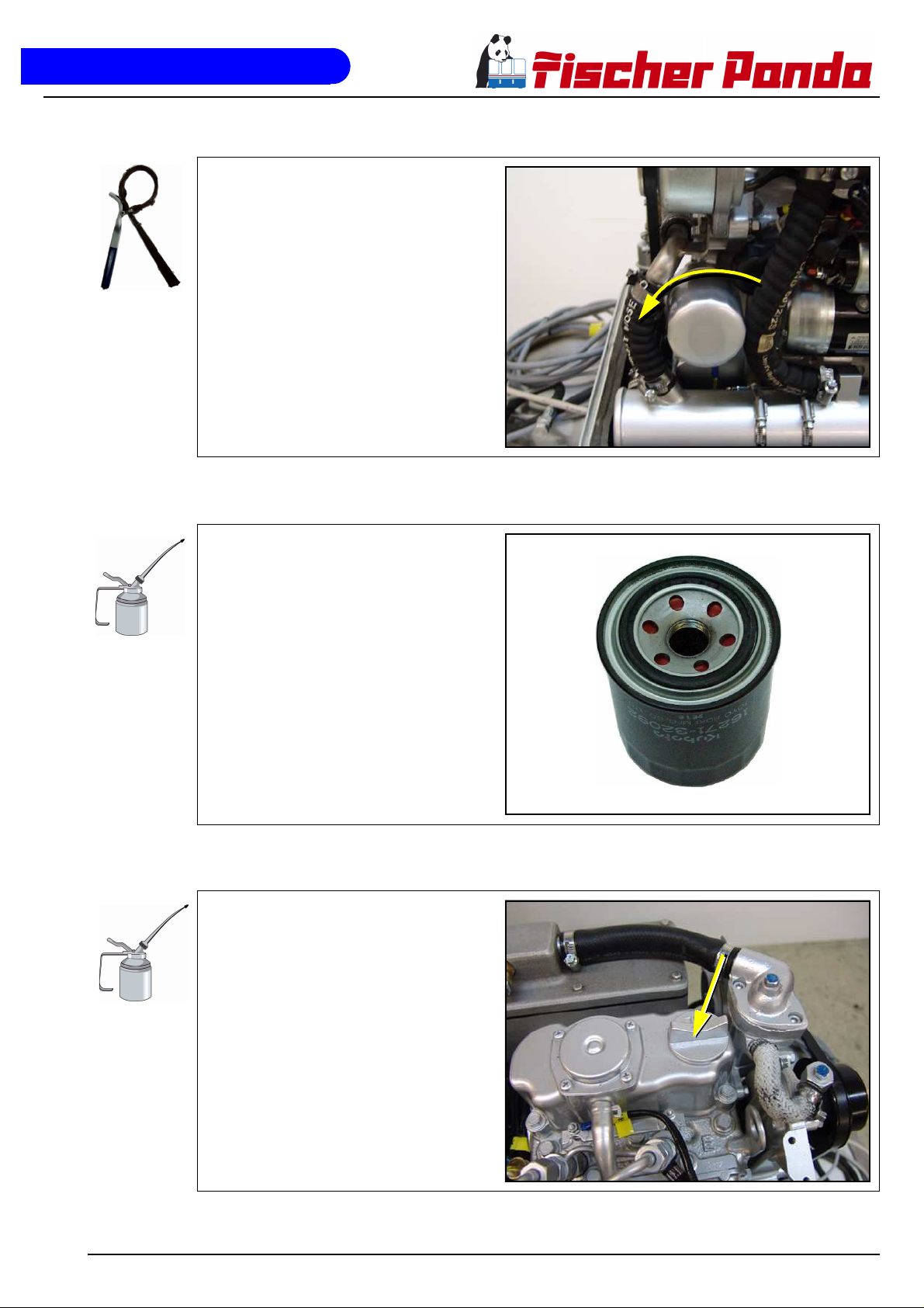
The oil filter can be loosened by means of
an oil filter strap.
Fig. E.2.1-4: Oil filter change
Oil filter gasket
The gasket should be coated with oil
before inserting the new oil filter.
Tighten the oil filter by hand only.
Fig. E.2.1-5: Oil filter gasket
Refill Oil
New oil is poured in, after opening the cap
of the oil filler neck. Please wait a
moment, before measuring the oil level;
the oil must first settle in the sump.
Fig. E.2.1-6: Oil filler neck
16.1.09 Panda_6000i_System_eng_s01835.book.R01 - Chapter E: Maintenance Instructions Page 55
Page 56
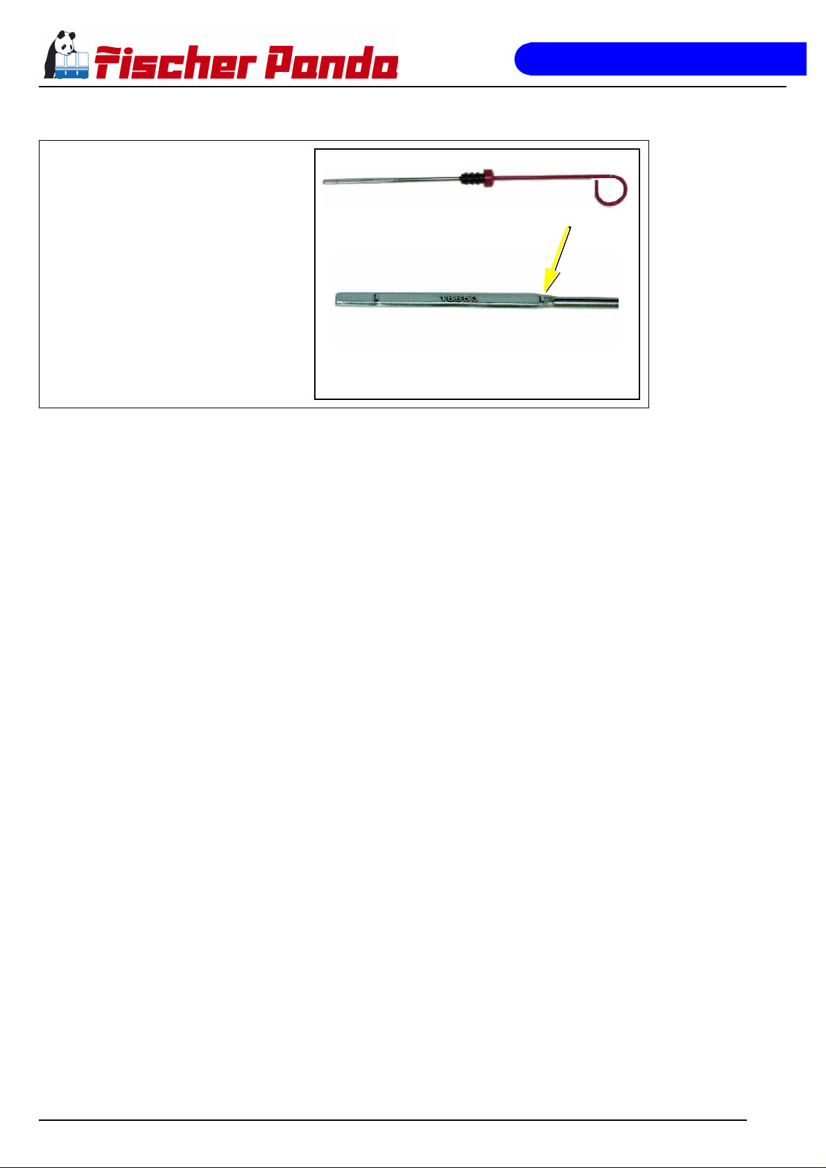
Oil Dipstick
The oil level is checked by use of the
engine oil dipstick. The prescribed filling
level may not exceed the "Max"marking.
Fig. E.2.1-7: Oil dipstick
Maintenance Instructions
Page 56 Panda_6000i_System_eng_s01835.book.R01 - Chapter E: Maintenance Instructions 16.1.09
Page 57
Maintenance Instructions
1
2
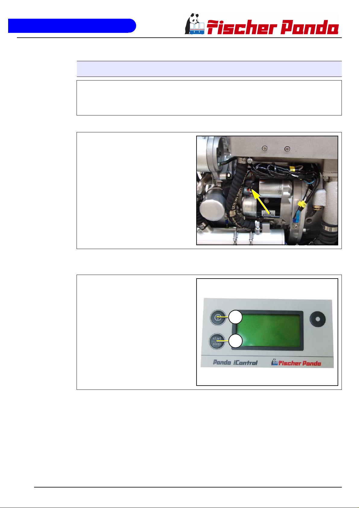
E.3 Ventilating the fuel system
Normally, the fuel system is designed to ventilate air itself i.e. as soon as the electric starter motor
starts operation the fuel pump starts working and the fuel system will be de-aerated after some
time automatically. It is nevertheless essential to ventilate the system as follows prior to the first
operation (as all hoses are empty):
1. Take off the plug at the solenoid of the
starter motor.
Fig. E.3-1: Starter motor
2. Switch the panel „ON“ (1 = „ON/OFFbutton).
3. Press „START“-button (2). The fuel
pump runs audible.
Fig. E.3-2: iControl panel
16.1.09 Panda_6000i_System_eng_s01835.book.R01 - Chapter E: Maintenance Instructions Page 57
Page 58
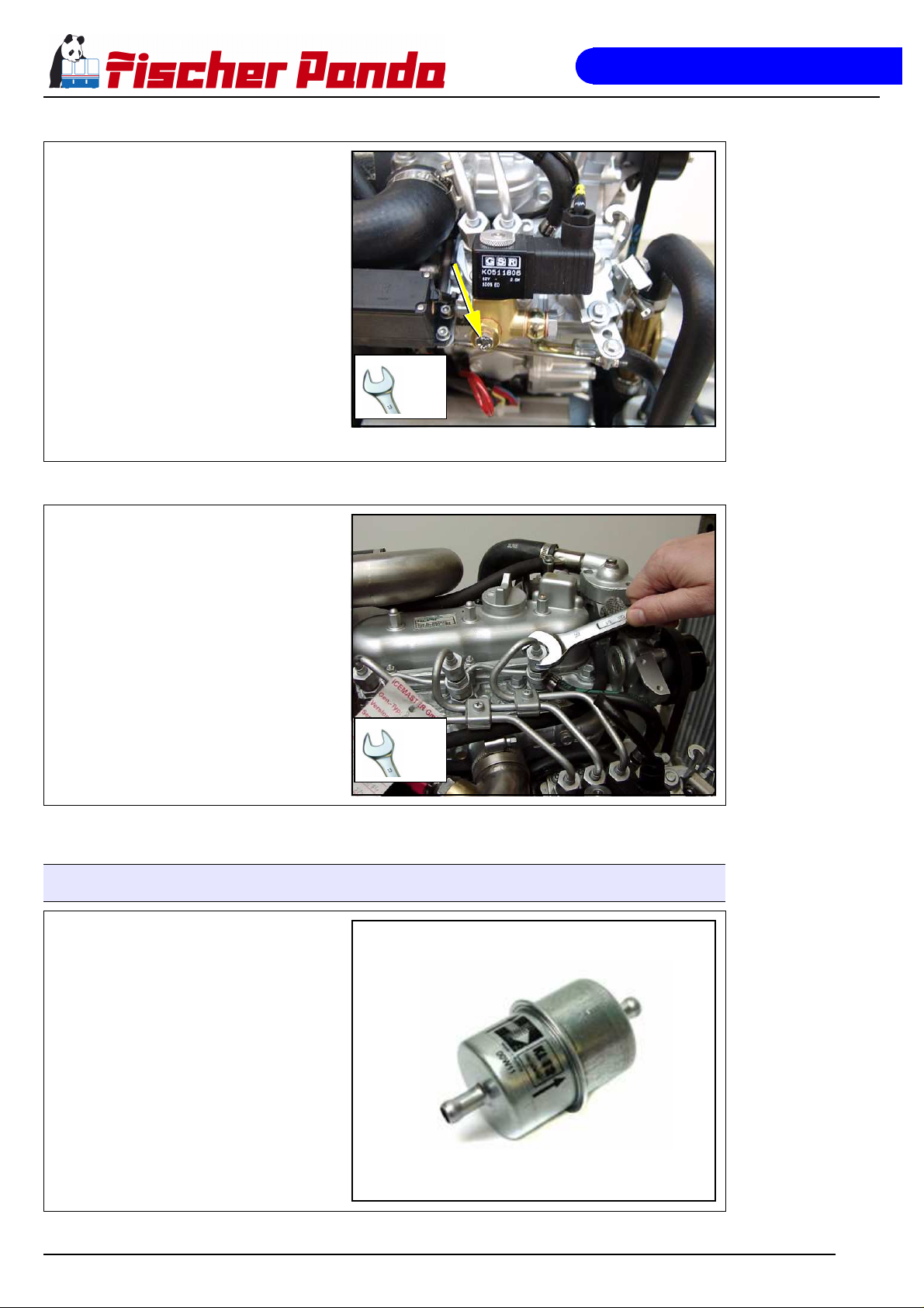
4. Open the ventilation screw located at
10
17
the fuel solenoid valve. The „START“
button must continue to be pressed,
whilst opening the screw. A large cloth
or Kleenex tissue must be laid beneath
the connection to prevent escaping
fuel running into the capsule. If the fuel
runs out without air bubbles, then the
ventilation screw can be closed. Only
then may the „START“ button be
released.
5. Switch the panel „OFF“.
This procedure must be repeated
several times,until fuel (nonporously)
withdraws perfectly at the ventilation screw.
Fig. E.3-3: Ventilation screw at the fuel solenoid valve
6. Pressing the starter button can now
start the machine. The machine should
start after a short period.
7. If this does not occur, then a connecting nut fitted to the injection line must
be loosened and starting procedure
repeated. Retighten the washers after
successfully starting. The injection line
must be raised by several millimetres.
8. Switch main switch "OFF"
Maintenance Instructions
Fig. E.3-4: Injection nozzles
E.3.1 Replace of the fuel filter
Exchanging the filter, depending upon fuel
contamination, should take place after 300
operational hours at the very least. The
inlet must be clamped, before exchanging
the filter.
Remove the hoses from the used filter
and fasten them to the new filter. The
arrow on the filter housing indicates the
direction of the fuel flow. A clogged filter
causes a decreased power output of the
generator.
Fig. E.3.1-1: Fuel filter
Page 58 Panda_6000i_System_eng_s01835.book.R01 - Chapter E: Maintenance Instructions 16.1.09
Page 59
Maintenance Instructions
E.3.2 Checking the water separator in the fuel supply
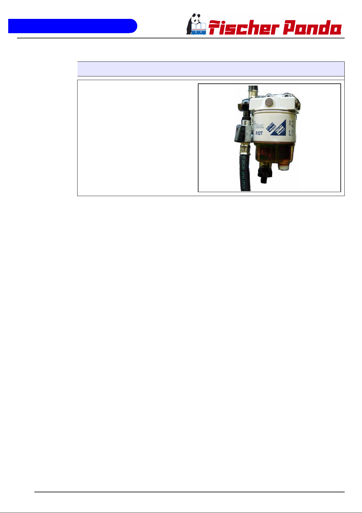
The pre-filter with water separator has a
cock underneath, by which means the
water can be drained.
This water sinks to the bottom, due to its
density. It is heavier than the diesel
Fig. E.3.2-1: Pre-filter with water separator
16.1.09 Panda_6000i_System_eng_s01835.book.R01 - Chapter E: Maintenance Instructions Page 59
Page 60
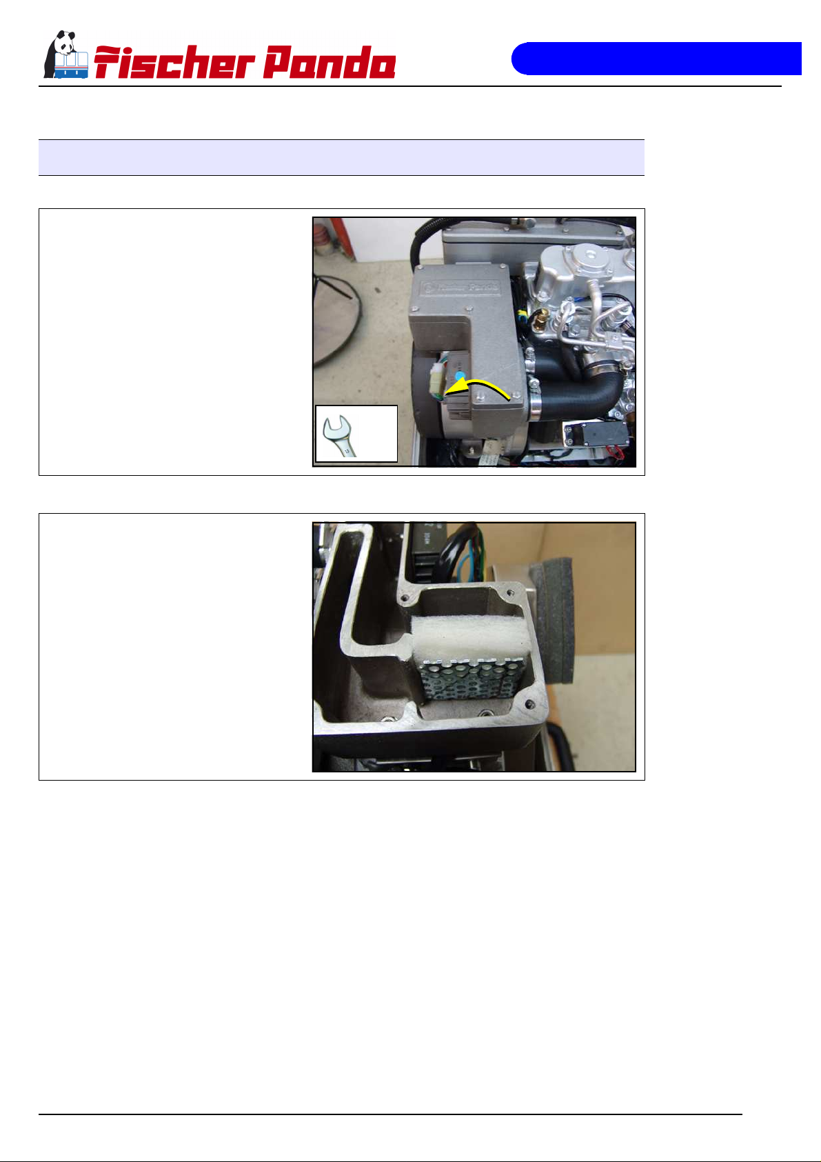
E.4 Replace the air filter mat
8
1. Open the air suction housing by loosen
the six screws on the housing cover.
Maintenance Instructions
2. Change the air filter mat.
3. Close the suction air housing.
Fig. E.4-1: Air suction housing
Fig. E.4-2: Opened air suction housing
Page 60 Panda_6000i_System_eng_s01835.book.R01 - Chapter E: Maintenance Instructions 16.1.09
Page 61
Maintenance Instructions
10
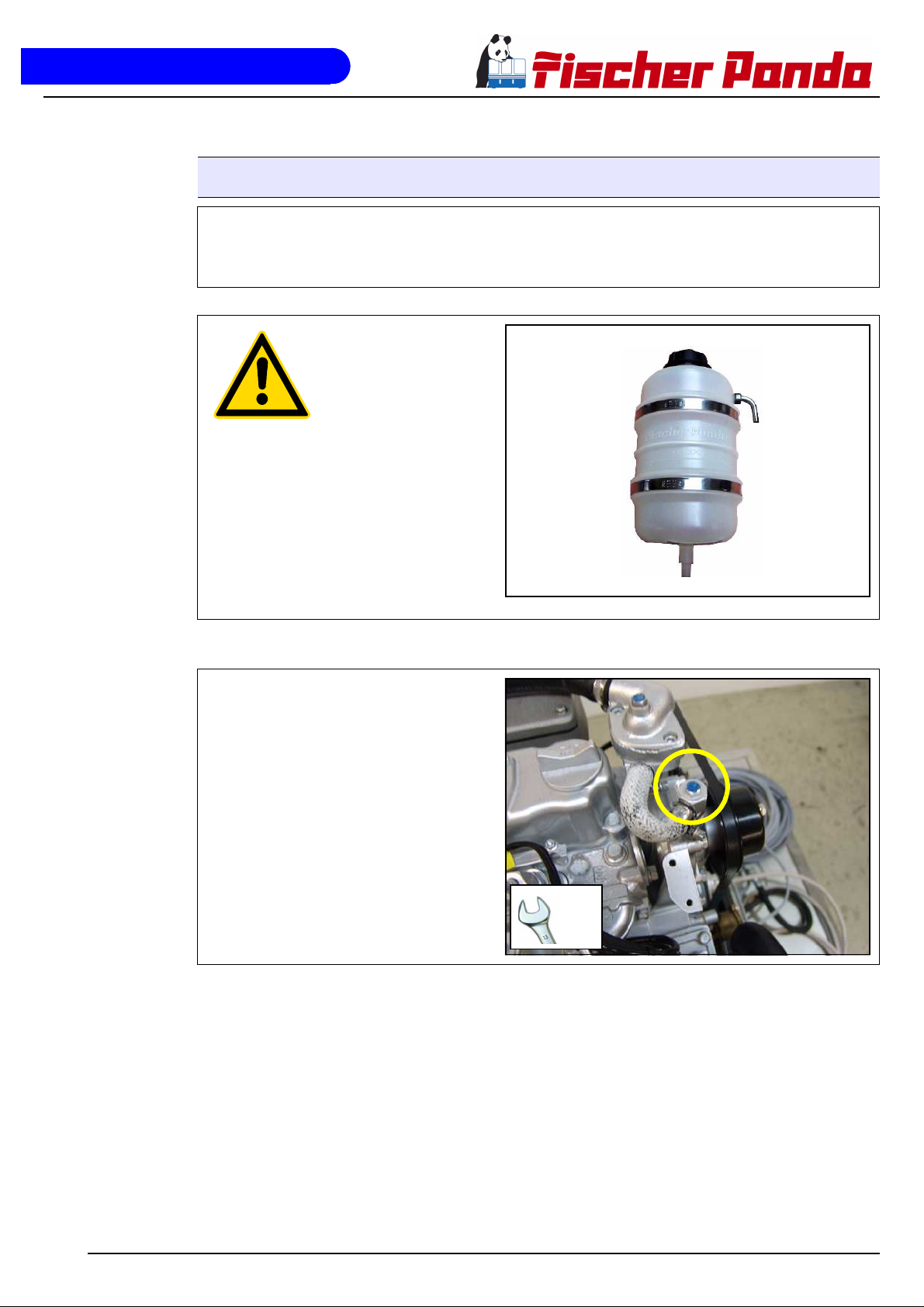
E.5 Ventilation of the Coolant Circuit / Freshwater
Special notes for the ventilation of the cooling system
If the cooling water is drained, or if other air has entered the cooling system, it is necessary to
ventilate the cooling system. This ventilating procedure must be repeated several times:
Pay attention that the external coolant
expansion tank is connected with the
generator by the intended connection
point.
ATTENTION! The
generator must be
switched off before
opening the ventilating points!
Further it should be guaranteed that the
expansion tank is attached in sufficient
height (600 m) over the level of the generator exhaust elbow union.
Fig. E.5-1: Expansion tank
1. Open the ventilating screw above the
cooling water pump casing.
Fig. E.5-2: Ventilating screw
16.1.09 Panda_6000i_System_eng_s01835.book.R01 - Chapter E: Maintenance Instructions Page 61
Page 62
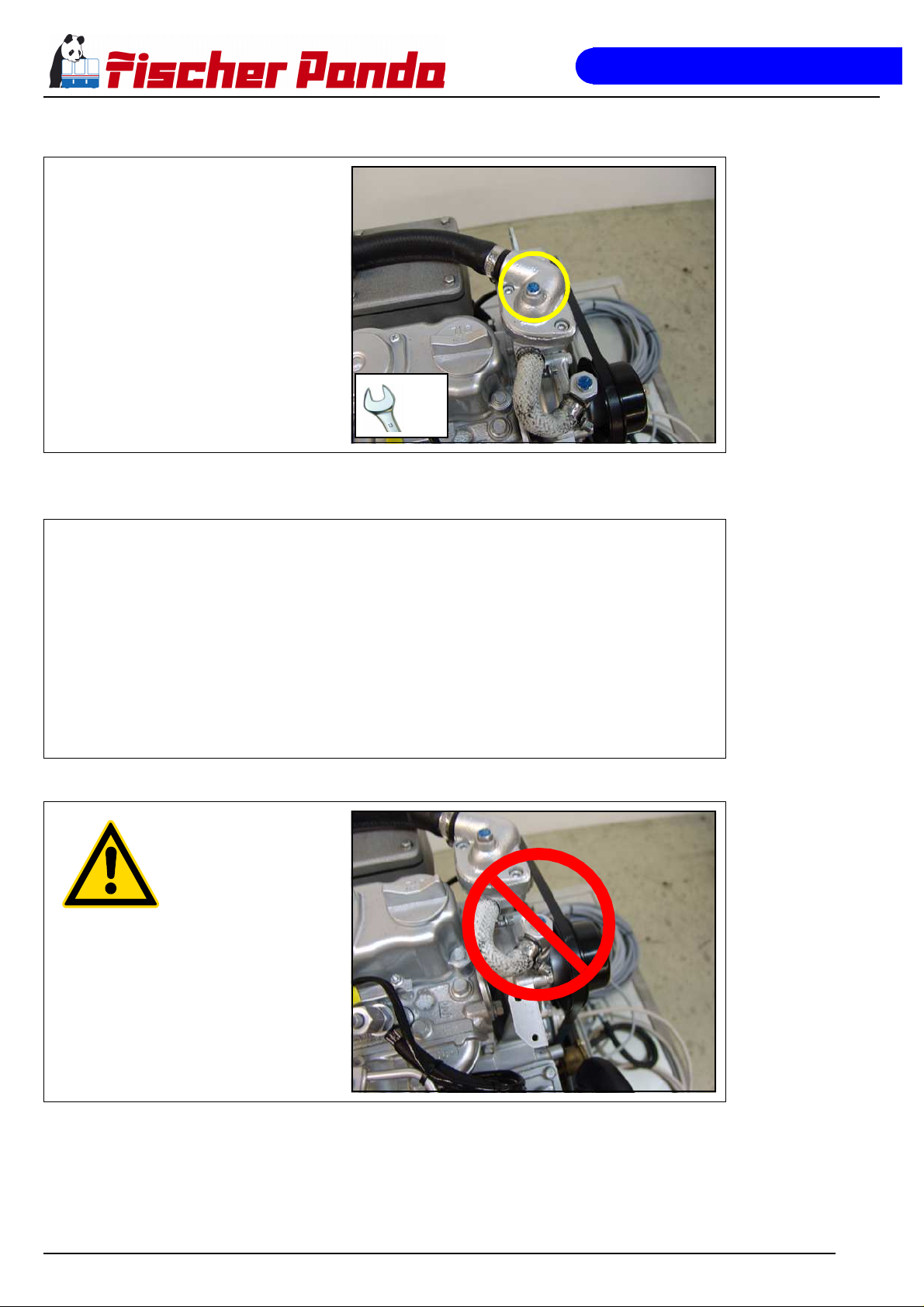
2. Open the ventilating screw on the ther-
10
mostat casing.
Fig. E.5-3: Ventilating screw on the thermostat housing
Maintenance Instructions
3. Now the cooling water is only filled over the external expansion tank. This is connected by 2
hoses with the genset.
The external expansion tank should be filled in the cold condition only up to maximally
20%. It is very important that a large extension space over the cooling water level remains.
Repeat this procedure several times.
If no change of the cooling water level can be determined, the generator is started for 5 minutes.
Afterwards repeat the ventilation two - three times.
It is meaningful to repeat the ventilation procedure also after some days again to guarantee that
in the system remained bubbles are removed.
The ventilation screw
above the cooling water
pump casing may not
be opened under any
circumstances, whilst
the generator is run-
ning. Air will be sucked
through the opening, if this should happen
by mistake. Venting the whole system
afterwards is necessary and very difficult.
Fig. E.5-4: Ventilation screw above the cooling water pump casing
Page 62 Panda_6000i_System_eng_s01835.book.R01 - Chapter E: Maintenance Instructions 16.1.09
Page 63
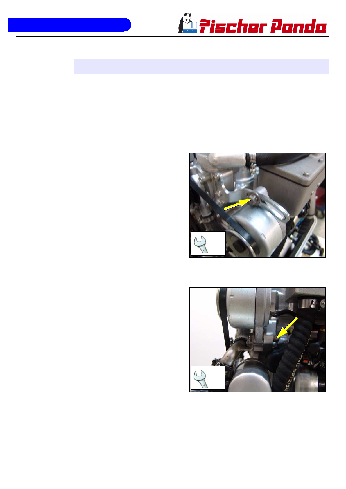
Maintenance Instructions
13
13
E.6 Replace of the v-belt for the internal cooling water pump
The relative high ambient temperature in the closed sound insulated capsule (about 85°C) can be
a reason for a reduced lifespan of the v-belts. It is possible that the "softener" in the rubber compound lose their effect after a short operating time because the air in the sound insulated capsule
can be relative warm and dry. The v-belt must be controlled at very short time intervals. It may be
required to change the v-belt after several weeks because of unfavourable conditions. Therefore,
control should be carried out after an interval of 150 operating hours. The v-belt is a wearing part.
There should be enough spare v-belts on board. We recommend that you have the respective
manual within reach.
1. Loosen the screw on the deflection
pulley bracket
Fig. E.6-1: Screw above the alternator
2. Loosen the screw beneath the alternator
Fig. E.6-2: Screw beneath the alternator
16.1.09 Panda_6000i_System_eng_s01835.book.R01 - Chapter E: Maintenance Instructions Page 63
Page 64
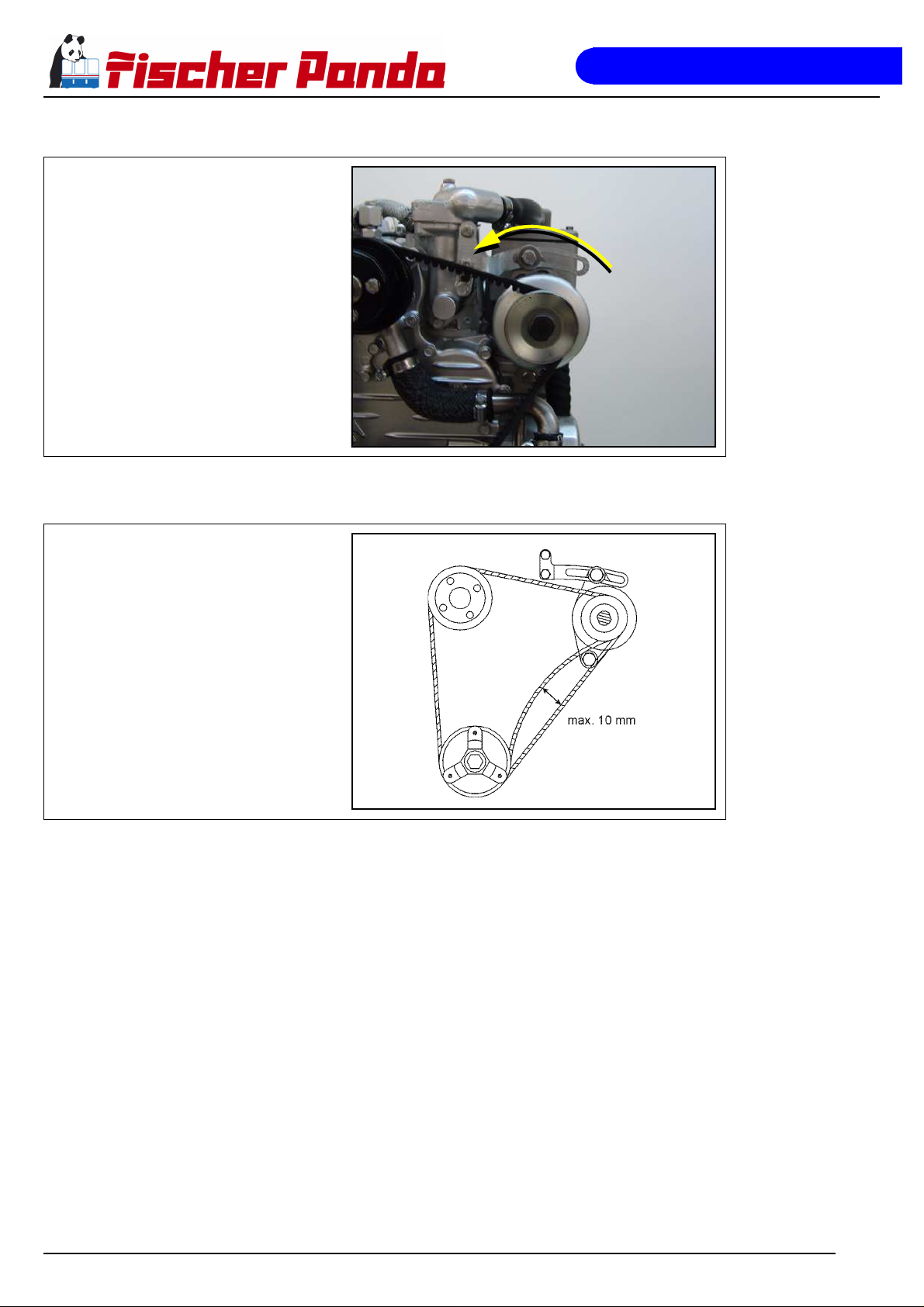
3. Press the alternator in the direction of
the thermostat casing.
4. Replace the v-belt.
Fig. E.6-3: DC alternator
Maintenance Instructions
5. Re-tighten V-belt
The v-belt should only be tightened to
the extent that it can be pushed to the
length of a thumb (approx. 10 mm).
6. Re-tighten the screws above and
below the alternator.
Fig. E.6-4: Drawing v-belt
Page 64 Panda_6000i_System_eng_s01835.book.R01 - Chapter E: Maintenance Instructions 16.1.09
Page 65
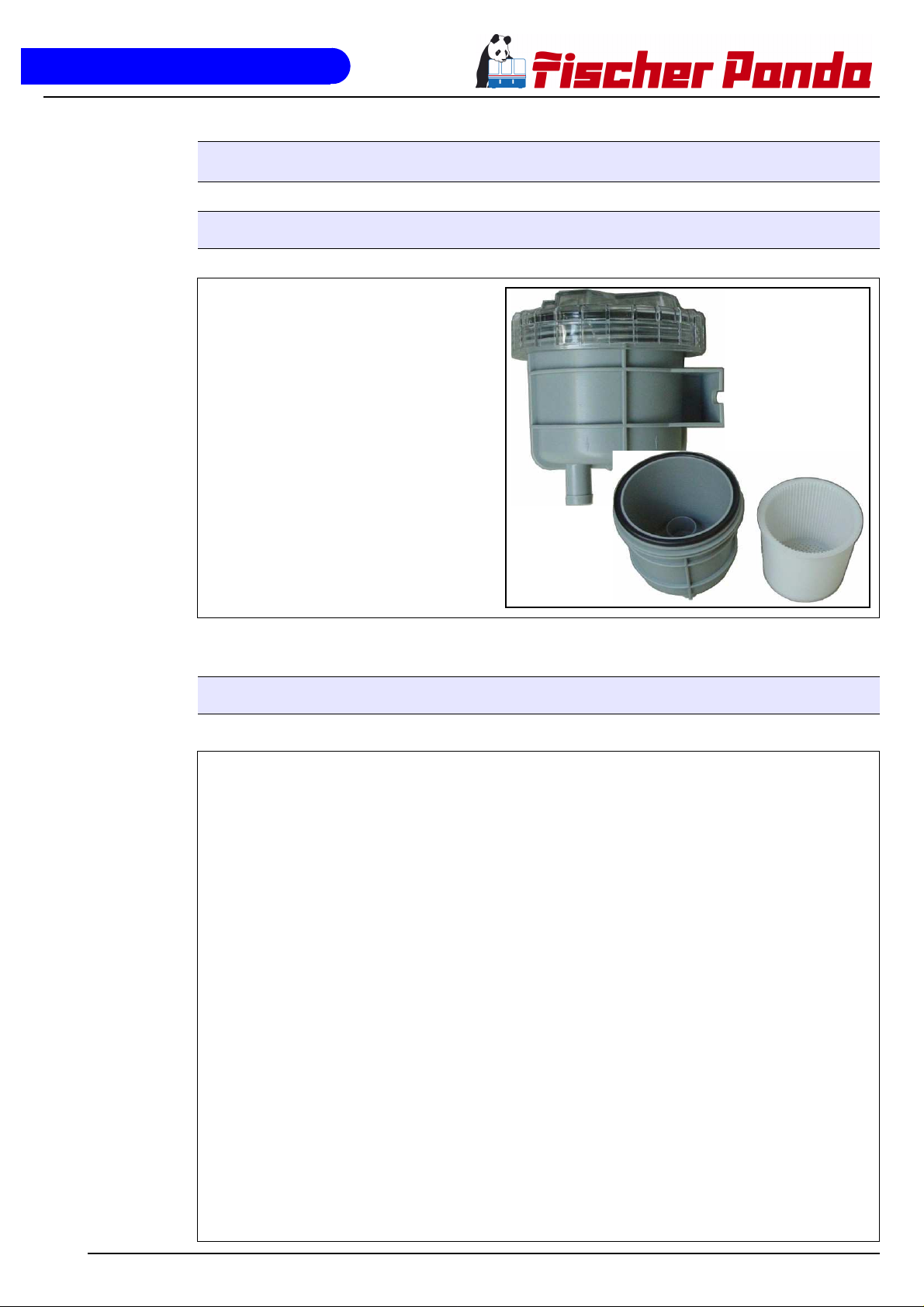
Maintenance Instructions
E.7 The Raw water circuit
E.7.1 Clean raw water filter
Residue should be regularly removed
from the seawater filter. The seacock
must, in each case, be closed first. It often
suffices to merely hit the filter punnet.
If water should seep through the cover of
the raw water filter, this may never be sealed with adhesive or sealant. The cause
for the leakage must be sought. The
sealing ring between caps and filter holders must be exchanged in the simplest
cases.
Fig. E.7.1-1: Raw water filter
E.7.2 Reason for frequent impeller wear
1. Unreasonable operating conditions
The Cooling water pump Impeller must be regarded as a wearing part. The life expectancy of an
impeller can vary greatly and depends exclusively upon the operating conditions. The PANDA
Generator cooling pumps are so designed that the speed of the pump in comparison to other
generators is relatively low. This has a positive effect on the life expectancy of the pump.
2. Longer Suction Distance of Cooling Water
If the cooling water suction distance is long, or is blocked, this has a negative effect on the impeller, so that an under-pressure occurs in the cooling water suction area. This can reduce the
efficiency of the impeller and place strain on the blades. This can greatly reduce the life expectancy.
3. Operating in contaminated waters
The impeller is placed under great strain in waters with high contamination. The use of the impeller in coral waters is also critical. There are known cases, whereby the impeller was so fatigued
after 100 hours use, that the lip seals were grinded away by the shaft. In these cases sharp crystal parts from the coral press into the rubber seals and act as a grinding material on the stainless
steel shaft of the impeller pump.
4. Generator mounted above the water level
It is especially disadvantageous for the impeller pump, if the generator is mounted above the
water level. This means that a few seconds will pass before the impeller can suck in cooling
water. This short dry running period damages the impeller. The increased wear can also lead to a
breakdown. (See special instruction: "Effect on the impeller pump, if the generator is mounted
above the water line").
16.1.09 Panda_6000i_System_eng_s01835.book.R01 - Chapter E: Maintenance Instructions Page 65
Page 66
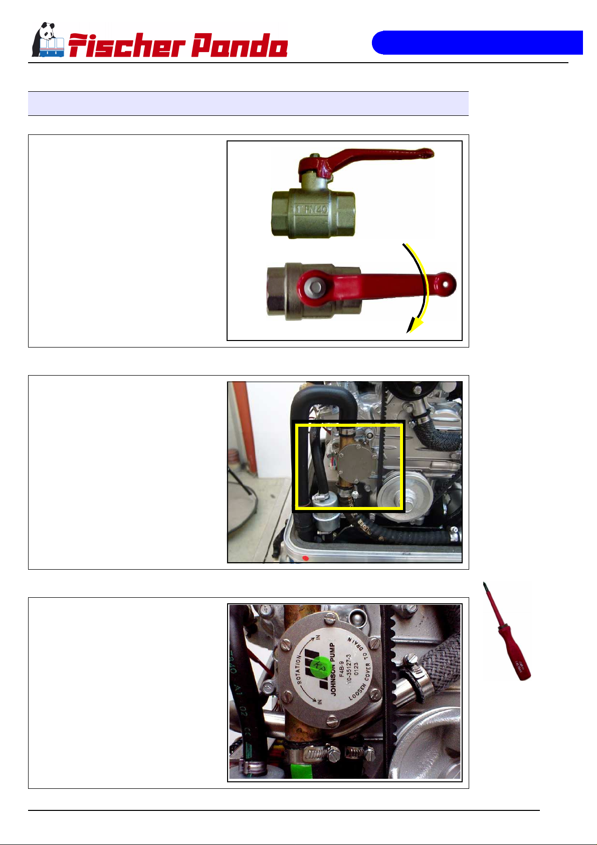
E.7.3 Replace the impeller
1. Close the raw water valve.
Maintenance Instructions
Fig. E.7.3-1: Raw water valve
2. The raw water pump is located on the
front side of the genset.
Fig. E.7.3-2: Raw water pump
3. Remove the cover of the raw water
pump by loosen the screws from the
housing.
Fig. E.7.3-3: Cover raw water pump
Page 66 Panda_6000i_System_eng_s01835.book.R01 - Chapter E: Maintenance Instructions 16.1.09
Page 67
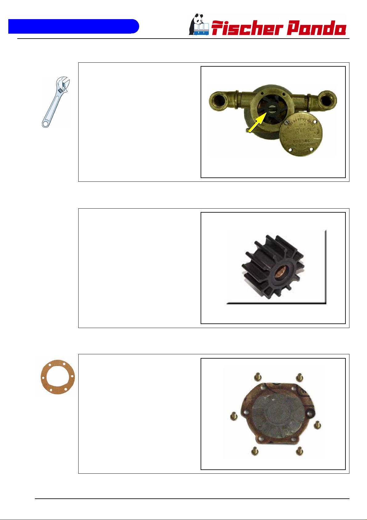
Maintenance Instructions
4. Remove the impeller from the shaft by
means of multi grip pliers..
5. Mark the impeller, to make sure that it
is in the correct position when re-installation is carried out.
Fig. E.7.3-4: Impeller
6. Check the impeller for damage and
replace it if necessary.
7. The impeller should have been lubricated with glycerine or with a non-mineral
oil based lubricated e.g. silicone spray,
before re-insertion into the housing.
Attention: This is very important,
because the impeller can quickly be
damaged.
Fig. E.7.3-5: Impeller
8. Attach the impeller to the pump shaft (if
the old impeller is re-used, initially
check the marking).
9. Fastening the cover and use a new
seal.
Fig. E.7.3-6: Cover pump shaft
16.1.09 Panda_6000i_System_eng_s01835.book.R01 - Chapter E: Maintenance Instructions Page 67
Page 68

Maintenance Instructions
E.8 Conservation of the generator (long operation interruption)
E.8.1 Measures for preparation of winter storage
1. Rinse seawater circuit with an anti-freeze solution, if this contains a corrosion protection solution. The seawater intake must be stopped at the seacock. The anti-freeze protection mixture
is to be sucked up from a container by means of a hose connection. The cooling water mixed
with the exhaust gases should be fed back to the suction container. The circuit must be kept
upright some minutes to ensure the anti-freeze protection mixture reaches all parts of the cooling system.
2. The anti-freeze mixture concentration in the internal cooling circuit must be checked with a
suitable measuring instrument. The concentration must be adequate for the lowest expected
temperatures.
3. Clean seawater filter and check seal.
4. Check seacock for practicability. And spray with a corrosion protection oil from the inside or
lubricate with acid-resistant grease.
5. Check all hoses and hose connectors for good condition. The rubber hoses are very sensitive
to environmental influences. They can deteriorate quickly in environments with dry air, light oil,
fuel fumes and increased temperatures. The hoses must be checked regularly for elasticity.
The hoses must be renewed once in the year in particular operating situations.
6. Doubly check the hose connections at all seawater valves, and if possible protect them with
double hose clamps.
7. Dismount the cooling water pump impeller and check for wear. The impeller may not remain in
the pump. It must be greased with Vaseline and be kept in a dark place. It can be re-integrated
again into the pump, during the spring, if it is in good condition. The impeller is a wearing part,
and it is recommended that it is always renewed in the spring, depending upon the number of
hours the generator has been running.
8. Control of the vent valve at the seawater inlet. A vent valve is always necessary, if the generator is installed below the waterline. The vent valve must also be regularly checked during the
season. The vent valve should always be disassembled, checked and greased during winter
storage. Hardened or dirty parts are to be replaced.
9. Check water lock: If the generator were rinsed with an anti-freeze mixture, the anti-freeze mixture can escape from the water lock. If the generator were rinsed with fresh water, the water in
the water lock must be drained. Otherwise there is a danger of the collector being destroyed
by ice through expansion.
10.Check the exhaust/water separator for leakage and whether the hose connections at the lower
surface of the separation unit are in normal condition. (in the case of extremely sulphurous
fuels, it is possible that high-grade steel tube ends are attacked.)
11.Check all construction units of the generator inside the sound cover for leakages. If there are
traces of humidity in the sound cover, the cover must be dried. Furthermore, the cause for
damp must be searched and eliminated.
Page 68 Panda_6000i_System_eng_s01835.book.R01 - Chapter E: Maintenance Instructions 16.1.09
Page 69

Maintenance Instructions
E.8.1 Measures for preparation of winter storage
12.During the winter storage the upper section of the sound inulated capsule must be taken off, in
order to avoid condensed moisture formation, if traces of humidity remain in the sound insulation capsule inside casing by leakages in the seawater circuit.
13.The generator housing and the housing of the engine should be sprayed with a corrosion protection oil before the winter storage. This procedure is recommended also in the season. This
procedure can avoid that arising and humidity marks on the surface of the aluminum construction units be noticed too late.
14.Disconnect the starter battery (positive and negative pole).
15.Lubricate the spindle for the number of revolutions adjustment device with a special lubricant
(Antiseize grease).
16.Check cooling water connection block at the generator housing on traces of corrosion and if
necessary renew. (Only such traces are to be considered, which refer to clear "blossoming" of
the material. If the surface is only grey coated, this is only an indication for the fact that aluminum came into contact with condensed moisture.)
17.Use of a air dehumidifier. The best way to protect a yacht in the winter storage against
damage by humidity is, to places a air dehumidifier inside the ship and locks all hatches. The
devices have a hygrometer, which switches the device off, if the humidity is under the adjusted
value. There is no better method, in order to protect pads, cable, electronics, wood, engines
etc. optimally against any rotting by humidity.
E.8.2 Initiation during spring
• Before starting, turn the engine once with the hand, in order to eliminate the beginnings of existing corrosion to the bushes. If necessarily carry out normal engine inspection.
• Change engine oil and engine oil filters.
• Reintegrate the impeller of the cooling water pump and check pump for leakage.
• Charge starter battery of the generator, connect cables and check battery voltage.
• Start generator and check the basic adjustments of the generator such as voltage, speed regulation etc...
• Check all switching off devices for function by operational procedures.
Fischer Panda does not take over adhesion for possible damages!
16.1.09 Panda_6000i_System_eng_s01835.book.R01 - Chapter E: Maintenance Instructions Page 69
Page 70

Maintenance Instructions
Intentionally Blank
Page 70 Panda_6000i_System_eng_s01835.book.R01 - Chapter E: Maintenance Instructions 16.1.09
Page 71
Tables
F. Tables
F.1 Troubleshooting
GENERATOR OUTPUT VOLTAGE TOO LOW
If the generator delivers less than 24V current ("undervoltage"), there can be various reasons for this:
PGMi is overloaded. Reduce the electrical load. (Switch off load)
Motor is not reaching the rated rpm. Refer to "motor faults" section.
MOTOR DOES NOT TURN OVER WHEN STARTING
Cause Solution
Cause Solution
Battery main switch is switched off. Check the position of the battery main switch, if neces-
sary switch on..
Battery voltage not sufficient. Check that connection is firm and whether corrosion
has occurred..
Starting current fault. The voltage of full batteries fall to a maximum of 11V.
The wiring is severed if the voltage does not drop. The
battery is discharged if the voltage drops further.
MOTOR TURNS OVER BUT DOES NOT START
Cause Solution
Stop solenoid valve not opening. Check wire connections and circuitry to solenoid valve.
(ref. DC wiring diagram: Relay K2, Fuse)
Fuel pump does not operate. Check fuel-filter and pump: clean if necessary.
Lack of fuel. Check fuel supply.
Glow-plugs not working correctly. Check glow plugs and heating time.
Too much air in fuel lines. Test fuel system for leakage. Bleed air from fuel system
(refer to section "Air-bleeding of the Fuel System").
Fuel filter blocked. Replace fuel filter.
Low compression pressure. See Kubota motor-manual.
16.1.09 AGT-DC_PMS_144V_s01790_Operation instruction.R01 - Chapter F: Tables Page 71
Page 72
MOTOR DOES NOT TURN OVER AT THE NORMAL SPEED DURING THE STARTING PROCESS
Cause Solution
Starter battery voltage insufficient. Check battery.
Damaged bearing(s) piston (seized). Repairs need to be carried out by Kubota-Service.
(refer to Kubota motor-manual)
Cooling water in combustion chamber. 1. Turn generator "OFF" at control panel.
2. Remove the glow plug (see Kubota-manual).
3. Rotate the motor by hand carefully.
4. Check if there is water in the oil and change both oil
and filter if necessary.
5. Determine cause for excess water in the combustion
chamber. The excess water can be caused by a defective air vent in the cooling water system, which should
be checked and cleaned, or replaced if faulty.
Tables
MOTOR RUNS IRREGULARLY
Cause Solution
Faulty centrifugal injector governor. Have the centrifugal governor inspected by a Kubota-
Service technician.
Too much air in fuel lines. Bleed air from fuel system.
DROP IN THE SPEED OF THE MOTOR
Cause Solution
Too much oil. Drain oil.
Lack of fuel. Check fuel supply system:
- fuel filter, renew if necessary
- check fuel pump
- check fuel lines (bleed if necessary)
Lack of intake air. Check air intake paths.
Check and clean air filter (and intake muffler if instal-
led).
Generator overloaded by too many load. Reduce the electrical load (switch off load).
Defective generator (windings, bearings, or other). Generator must be sent to manufacturer for repair of
damaged bearings or winding.
Damaged engine. Repair of bearing damage, etc., by Kubota-Service.
Page 72 AGT-DC_PMS_144V_s01790_Operation instruction.R01 - Chapter F: Tables 16.1.09
Page 73
Tables
MOTOR SWITCHES ITSELF OFF
Cause Solution
Fuel solenoid valve or throttle shut solenoid is not switching off.
Check wire connections to solenoid. Check valve
functions as in the "Inlet Fuel Solenoid Valve" or in the
trottle shut off solenoid sections. Replace if necessary.
MOTOR STOPS BY ITSELF
Cause Solution
Lack of fuel. Check fuel supply system.
Excess heat in cooling system (thermo switch tripped)-
lack of cooling water. Is indicated on the remote control
Check cooling water system flow: water pump, inlet
water filter, extra heat exchanger coolant flow.
panel.
Lack of oil (oil pressure sensor tripped). Check oil-level and if necessary top up.
Check motor's oil-pressure and have repaired by
Kubota-Service if necessary.
SOOTY, BLACK EXHAUST
Cause Solution
Generator is overloaded. Check electrical load and switch off unnecessary load.
Insufficient intake air. Check intake air filter; clean if necessary.
Fuel injector nozzles faulty. Replace injector nozzles.
Valve clearance incorrect. Readjust valve clearance to correct value (refer to
Kubota-manual).
Poor fuel quality. Use better quality diesel (recommended: 2-D Diesel).
Poor combustion. Incorrect AFR (air/fuel ratio) due to motor timing adjust-
ment. Have motor serviced by Kubota.
Low compression pressure. See Kubota motor manual.
16.1.09 AGT-DC_PMS_144V_s01790_Operation instruction.R01 - Chapter F: Tables Page 73
Page 74
GENERATOR MUST BE SHUT OFF IMMEDIATELY IF:
Cause Solution
Tables
- motor rpm suddenly rises or drops
- unusual noise comes from genset
- exhaust colour suddenly becomes dark
- motor overheats
- oil pressure drops, oil light suddenly flashes
Refer to respective section of manual and if necessary,
have repaired by Kubota-Service, or Panda representative.
F.2 Technical data
F.2.1 Technical data generator
Generator Panda 6000i PMS
Generator type PM-Synchronous Generator
Winding type AGT
Wiring mode 3~
Protection mode IP 44
Insulation class H
Nominal voltage 2x300 V
Frequency 373 Hz
Nominal speed -> 2800 rpm
Max. current 2x5,7 A
Apparent power 6,0 kVA
Real power 6,0 kW
Power factor 1,0
Table 1: Technical data generator
Page 74 AGT-DC_PMS_144V_s01790_Operation instruction.R01 - Chapter F: Tables 16.1.09
Page 75

Tables
F.2.2 Technical data engine
Model Kubota Z 482
Type Vertical, water-cooled, 4-cycle diesel engine
No. cylinders 2
Bore [mm] 67
Stroke [mm] 68
Total displacement [ccm] 479
Combustion chamber Spherical type (E-TVCS)
SAE NET intermittent (SAE J1349) at 3600rpm [kW] 9,3
SAE NET continuous (SAE J1349) at 3600rpm [kW] 8,1
Maximum bare speed [rpm] 3800
Minumum bare idling speed [rpm] 900 to 1000
Order of firing 1-2
Direction of rotation Counter-clockwise (viewed from flywheel side)
Injection pump Bosch MD type mini pump
Injection pressure 13,73 MPa, 1991 psi (140kgf/cm²)
Injection timing (before T.D.C) 20°
Compression ratio 23,5 : 1
Fuel Diesle fuel No. 2-D
Lubrication (API classification) above CF grade
Dimension (lengthxwidthxheight) [mm] 351x389x520
Dry weight (BB spec.) [kg] 53,1
Starting system Cell starter (with glow plug)
Valve clearance (engine cold) [mm] 0,145 to 0,185
Cylinder head cover screw torque [Nm] 37,3 to 42,2
Lubrication oil capacity [l] (oil pan) 2,1(101mm)
2,5l (121mm)
Fuel consumption a [l]
Oil consumption max. 1% of fuel consumption
0,63 - 1,68
Permissible max. permanent tilt of engine a) 25° acr oss the longitudinal axis
b) 20° in the longitudinal direction
Table 2: Technical data engine
a. 0,35l/kW electrical power, the randomized values between 30% and 80% of the power rating.
16.1.09 AGT-DC_PMS_144V_s01790_Operation instruction.R01 - Chapter F: Tables Page 75
Page 76

Tables
Generatortype
Ø Cooling water conduit
Fresh water
[mm]
Raw water
[mm]
Ø Exhaust con-
duit
[mm]
Ø Fuel conduit
Supply
[mm]
Return
[mm]
Panda 6000i PMS 20 20 40 8 8
Table 3: Diameter of conduits
Wiring for vehicles.
single phase, not tin-plated, PVC-isolated.
nominal wire cross-section
[mm²]
allowed continous current (reference point)
at +30°C [A] at +50°C [A]
a
1 19 13,5
1,5 24 17,0
2,5 32 22,7
4 42 29,8
6 54 38,3
10 73 51,8
16 98 69,6
25 129 91,6
35 158 112
50 198 140
70 245 174
95 292 207
120 344 244
a. DIN VDE 0298, part4.
Table 4: Cable cross-section
Page 76 AGT-DC_PMS_144V_s01790_Operation instruction.R01 - Chapter F: Tables 16.1.09
Page 77
Tables
F.3 Engine oil specification
Engine oil classification
Operating range:
The operating range of an engine oil is determined by SAE class. "SAE" is for the union of American engineers
(Society of Automotives Engineers). The SAE class of an engine oil only informs over the viscosity of the oil (larger number = more viscous, lower number = more highly liquidly) e.g. to 0W, 10W, 15W, 20, 30, 40. The first number shows the liquid of cold weather, the second number refers to the fluidity with heat. Complete yearly oils have
usually SAE 10W-40, SAE 15W-40 etc.
Quality of oil:
The quality of an engine oil is specified by the API standard ("American Petroleum Institutes"). The API designation is to be found on each engine oil bundle. The first letter is always a C.
API C for diesel engines
The second letter is for the quality of the oil. The more highly the letter in the alphabet, the better the C für Dieselmotoren.
Examples for diesel engine oil:
API CG Engine oil for highest demands, turbo-tested
Engine oil types
above 25°C SAE30 or SAE10W-30, SAE10W-40
0°C to 25°C SAE20 or SAE10W-30, SAE10W-40
below 0°C SAE10W or SAE10W-30, SAE10W-40
Table 5: Engine oil specification
16.1.09 AGT-DC_PMS_144V_s01790_Operation instruction.R01 - Chapter F: Tables Page 77
Page 78
F.4 Coolant specifications
Use a mixture of water and antifreeze. The antifreeze needs to be suitable for aluminium. The antifreeze concentration must be regularly checked in the interests of safety.
Fischer Panda recommend to use the product: GLYSANTIN PROTECT PLUS/G 48
Engine coolant automotive industry Product description
Product name GLYSANTIN ® PROTECT PLUS / G48
Chemical nature Monoethylenglycol with inhibitors
Physical form Liquid
Chemical and physical properties
Tables
Reserve alkalinity of 10ml ASTM D 1121 13 – 15 ml HCl 01 mol/l
Density, 20°C DIN 51 757 procedure 4
1,121 – 1,123 g/cm
3
Water content DIN 51 777 part 1 max. 3,5 %
pH-value undiluted 7,1 – 7,3
Table 6: Coolant specification
Coolant mixture ratio
Water/antifreeze Temperature
70:30 -20°C
65:35 -25°C
60:40 -30°C
55:45 -35°C
50:50 -40°C
Table 7: Mixture ratio
Page 78 AGT-DC_PMS_144V_s01790_Operation instruction.R01 - Chapter F: Tables 16.1.09
Page 79
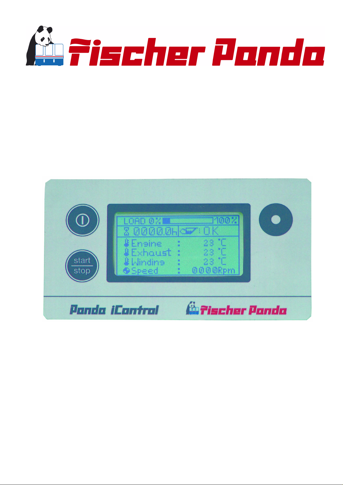
Panda i-series
Part 2: Panel Panda iControl Manual
Panel Panda iControl
Fischer Panda GmbH
iControl_eng.R03 16.1.09
Page 80
Current revision status
Document
Actual: Panda_iControl_eng.R03_16.1.09
Replace: Panda_iControl_eng.R02
Revision Page
Update the whole manual
connection to 6000i update
80
Page 81
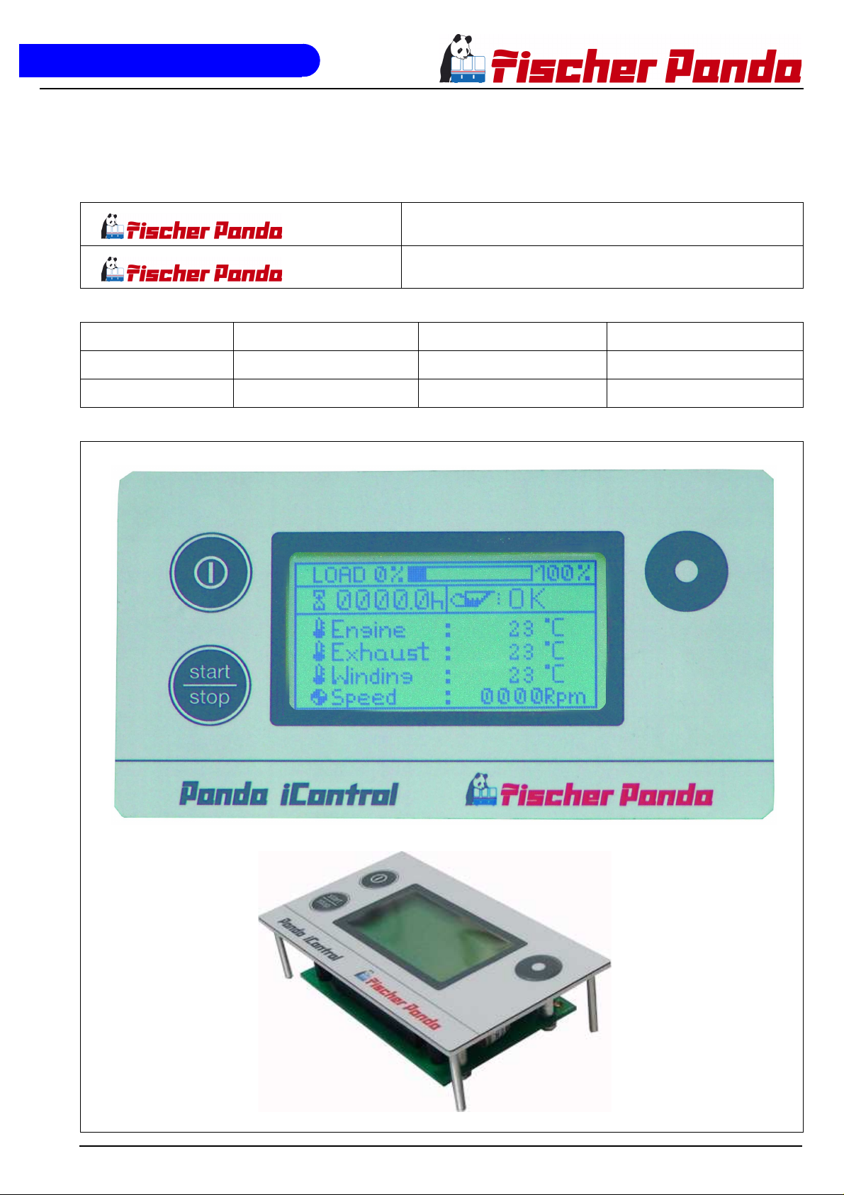
Panda iControl
A. Panda iControl
Fischer Panda Datasheet
Document Hardware Software
Actual: R04
Replace: R03
Art Nr.
Bez.
.
21.02.02.01H
Panda iControl
Panel_iControl_eng.fm Chapter A: Panda iControl - Page 81
Page 82
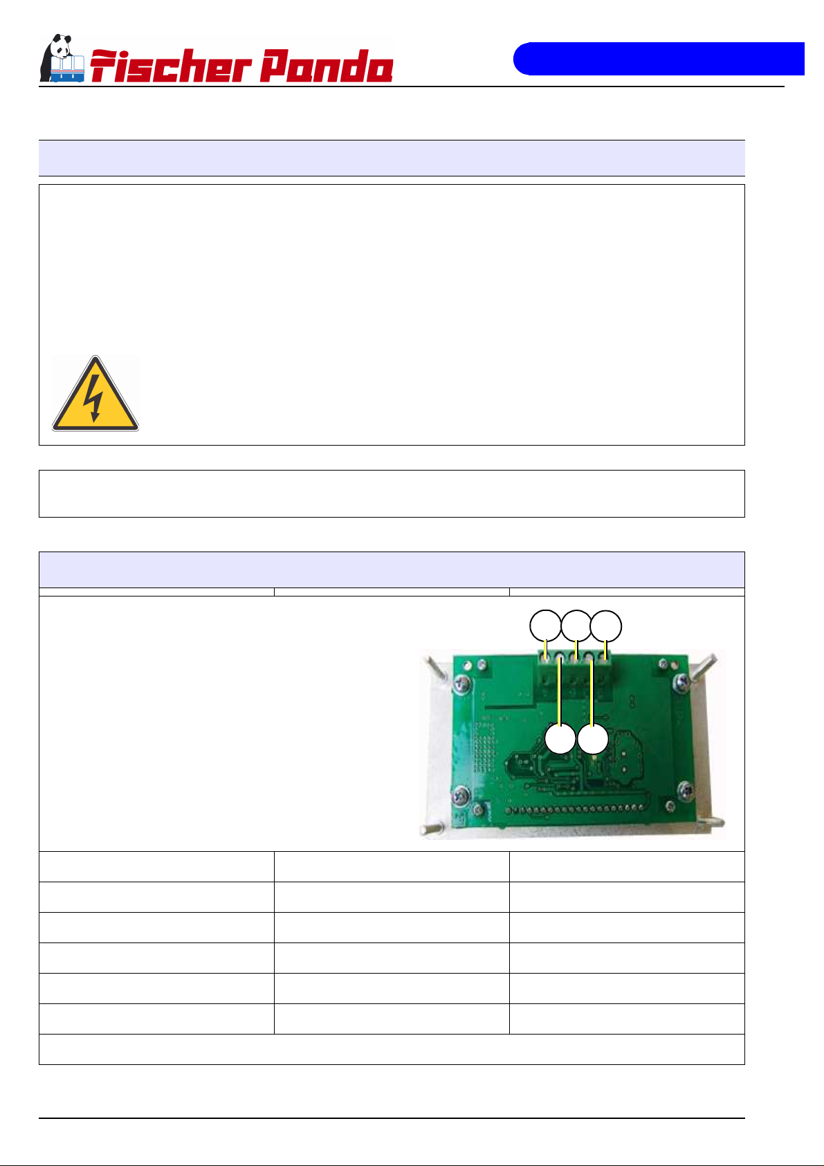
Panda iControl
1
3
5
2
4
Fischer Panda Datasheet
A.1 Safety instructions
The generator may not be taken into use with the cover removed.
The rotating parts (belt-pulley, belts, etc) must be covered and protected so that there is no danger to life and
body!
If a sound insulation cover must be produced at the place of installation, then well-placed signs must show that
the generator can only be switched on with a closed capsule.
All servicing-, maintenance or repair work may only be carried out, when the motor is not running.
Electrical power: DANGER TO LIVE!
Electrical voltages above 48 volts (battery chargers greater than 36 volts) are always dangerous
to life). The rules of the respective regional authority must be adhered to. Only an electrician
may carry out installation of the electrical connections for safety reasons.
Before start working at the Panda i-series generator (service, repair ect), diconnect the starter battery (First minus
cable, then positive cable), so that the generator cannot be unintentionally started.
A.2 Connection of the iControl
To connect the iConrol use the original prepared cable.
(6 wires shilded)
Terminator cablecolour 4000i cablecolour 6000i
1. U+ cablecolour brown brown
2. Gnd cablecolour brown-white grey
3. RZL cablecolour green green
4. D_A cablecolour blue white
5. D_B cablecolour blue-white yellow
Between clamp RZL(3) und Gnd(2) an automatik start device (Battery monitor) can be connected
Page 82 - Chapter A: Panda iControl Panel_iControl_eng.fm
Fig. A.2-1: Connection of the iControl
Page 83
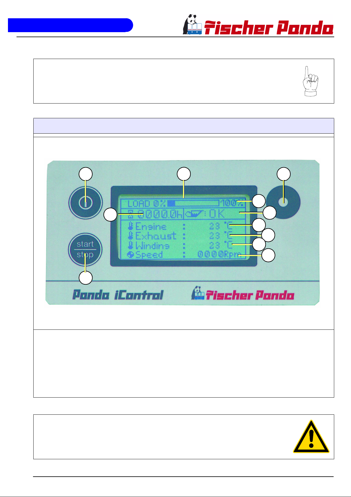
Panda iControl
2
4
1 3
2a
2b
2d
2c
2e
2f
2g
1. Button „on/off“
2. Display
2a. Load indication in %
2b. Oil pressure indication „OK“ oder „Fault“
2c. Engine temp. indication
2d. Exhaust elbow temp. indication
2e. Stator Winding temp. indication
2f. Engine rpm indication
2g. Operation hours
3. Button „enter“
4. Button „start/stop“
Note
Regarding to the open electric board the iControl panel has a protectrive class IP00.
Builded in a control board with a siutable seal (f.e. Sikaflex) IP66 can be reached.
A.3 Buttons and display of the iControl
Fischer Panda Datasheet
Warning! At the Electronic board is an voltage of 450V. Only special trained persons are
allowed to open the cover of the Electronic board. !!!DANGER TO LIVE!!!
Panel_iControl_eng.fm Chapter A: Panda iControl - Page 83
Fig. A.3-1: Buttons and diplay of the iControl
Page 84
Panda iControl
Fischer Panda Datasheet
A.4 Engine control
The iControl Panel and Electronic Board is for driving the Panda i-series generator. Push the „on/off“ button to
start the panel(1). The panel will come up in the „stand by mode“.
„stand by mode“
in the stand by mode the iControl checks the generator
- Display shows welcome screen
- the Led-Light will switch off after 2 min. (energie save)
- push the „enter“ button“ to reset the LED-Light timer
- start the generator with the „start/stop“ button --> „run mode“
- start the generator with the „automatic start“ option --> „run mode“
„run mode“
Generator was started with the “start/stop“ button or with the „automatic start option“
- Display light is on
- Display shows generator data
- stop the generator with the „start/stop“ button --> „standby mode“
- stop the generator with the „automatic start“ option --> „standby mode“
A.5 Operation manual
A.5.1 Daily routine checks before starting
1. Oil Level Control (ideal level: 2/3 of maximum).
AtTTENTION! OIL PRESSURE CONTROL!
True, the diesel motor automatically switches off when there is a lack of oil, but it is very damaging for the motor, if the oil level drops to
the lowest limit. Air can be sucked in suddenly when the boat rocks in heavy seas, if the oil level is at a minimum. This affects the
grease in the bearings. It is therefore necessary to check the oil level daily before initially running the generator. The oil level must be
topped up to the 2/3 of maximum level, if the level drops min. mark.
2. State of Cooling Water.
The external compensation tank should be filled up to a 1/3 level of in a cold state. It is very important that large expansion area
remains above the cooling water level.
3. Open Sea Cock for Cooling Water Intake.(if necessary)
For safety reasons, the seacock should be closed after the generator is switched off for a longer time. It should be re-opened before
starting the generator.
4. Check Raw water Filter.
The raw water filter must be regularly checked and cleaned. The impeller fatigue increases, if residual affects the raw water intake.
Page 84 - Chapter A: Panda iControl Panel_iControl_eng.fm
Page 85
Panda iControl
5. Check all Hose Connections and Hose Clamps are Leakage.
Leaks at hose connections must be immediately repaired, especially the raw water impeller pump. It is certainly possible that the raw
water impeller pump will produce leaks, depending upon the situation. (This can be caused by sand particles in the raw water etc.) In
this case, immediately exchange the pump, because the dripping water will be sprayed by the belt pulley into the sound insulated casing and can quickly cause corrosion.
6. Check all electrical Lead Terminal Contacts are Firm.
This is especially the case with the temperature switch contacts, which automatically switch off the generator in case of faults. There is
only safety if these systems are regularly checked, and these systems will protect the generator, when there is a fault.
7. Check the Motor and Generator Mounting Screws are Tight.
The mounting screws must be checked regularly to ensure the generator is safe. A visual check of these screws must be made, when
the oil level is checked.
8. Switch the Land Electricity/Generator Switch to Zero before Starting or Switch Off all the Load.
For the automatic option make shure that the load is connected to the PMGi only, when the nominal output of
Fischer Panda Datasheet
9. Check the Automatic Controls Functions and Oil Pressure.
Removing a cable end from the monitoring switch carries out this control test. The generator should then automatically switch off.
Please adhere to the inspection timetable (see Checklist in the appendix).
Attention! Make sure that the PMGi is connected with the generator. Never connect or disconnect the PMGi when the generator is running. This will destroy the PMGi. (it may burn
or explode)
A.5.2 General
Very low Temperatures
The generator is disigned to start at temperatures up to -20 ° C. Please make sure, that the fuel is siutable for
your temperature range.
The electronic of the iControl changes the pre-glow time at the generator start according to the actual generator
temperature. The normal time at a cold engine is 8 sec. The pre-glow times rises at temperatures below 8 ° C and
drops (down to 0 sec.) at temperatures over 40°C.
Tips regarding Starter Battery
Fischer Panda recommends the use of a normal starter battery. If a genset is required for extreme winter conditions, then the starter battery capacity should be doubled. It is recommended to charge the starter battery regularly
by a suitable battery-charging device (i.e., at least every 2 months). A correctly charged starter battery is necessary especially for low temperatures.
Panel_iControl_eng.fm Chapter A: Panda iControl - Page 85
Page 86
Panda iControl
Fischer Panda Datasheet
Engine Oil at winter conditions.
Make sure using a siutable engine oil at winter conditions.
Do not use start help sprays or similar.
A.5.3 Long time run of the generator
Make sure the PMGi is not overloaded. The PMGi will switch off in this case.
We recommend to calculate the normal load should be at 80 % of the nominal load of the generator and PMGi.
Normel load is in this case the load you need for a very long period. Nearly 100 % of the nominal power of the
generator and PMGi can be used for 2-3 hours without any problems.
A.5.4 Start of the generator
1. Open the fuel valve (if necessary)
2. Close the battery switch (if necessary)
3. Push "on/off" button (turn iControl on).
Panel comes up with „Welcome“ screen
4. Push the „start/stop“ button to switch from „Welcome“ to the „Main“ screen
Screen switch to „Main“ screen
5. Push „start/stop“ button
The Engine pre-glow and start. It is not allowed to run the starter motor for more than 10 sec. If the generator does not start within this
time, the start is blocked for 20 sec.
Please check if the fuel is present at the generator, before you try to start the generator again. (and if the fuel is siutable for the temperature range)
6. Switch on the load when the nominal output of 230V / 50Hz is reached at the PMGi. See “Automatic start” on
page 87.
ATTENTION: If there is difficulty in starting - close the seacock ( Panda Marine Generators only)
If the generator engine does not start immediately and further start attempts are necessary, then
the seacock MUST be closed (i.e. for ventilating the fuel lines etc.) The cooling water impeller
pump turns automatically and draws cooling water as long as the motor is turning. If the diesel
motor is running, the cooling water is blown out by the exhaust system gases. The cooling water
cannot be pressed through the exhaust as long as the diesel motor does not run at sufficient speed. This leads to
severe motor damage.
Open the seavalve as soon as the generator is started.
Page 86 - Chapter A: Panda iControl Panel_iControl_eng.fm
Page 87
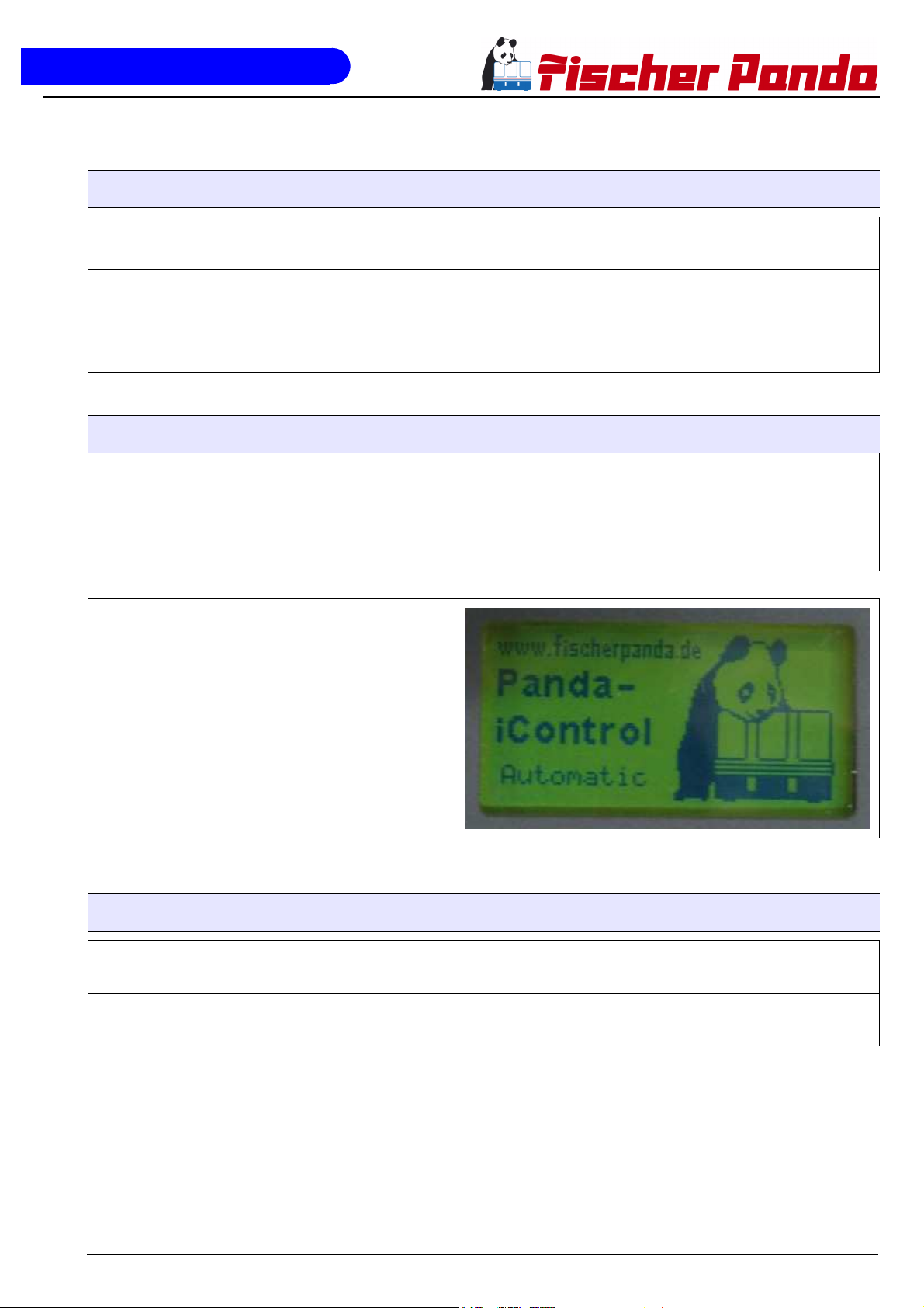
Panda iControl
A.5.5 Stop of the generator
1. At higher temperatures (over 25°C) the generator should run 5 min. after the load has been switched off in
order to cool down)
2. Push the „start/stop“ button to switch off the generator.
3. Close additional switches (battry, fuel ect.).
4. Push the „on/off“ button to turn off the iControl“.
A.5.6 Automatic start
The iControl has an „automatic start“ option at clamp RZL and Gnd. Close the connection of these clamps to start
the generator. Open it to stop the generator.
If you use this option make sure that the load is connected to the PMGi after the output has reached the nominal
230V / 50Hz and not to overload the PMGi (some electronic devices - such like air conditions - need an higher
starting current. You may use a relay which connects the load at 230V.
Fischer Panda Datasheet
To activate the automatic start:
1. Turn the panel on („on/off“ button)
2. Switch to „Main“ screen („start/stop“ button)
3. Activate automatic start („enter“ button)
To deactivate the automatic start, press the „enter“
button again or switch the panel off with the „on/off“
button
Fig. A.5.6-1: Display automatic start
A.5.7 Additional information
1. The revision of the hard and software is stored in the electronic memory and can be read out by the service
technican.
2. If the iControl is in the stand by mode and the battery voltage drops under 12.1V for more than 2 min., the
iControl shut the system off to prevent the battery for total discharge.
Panel_iControl_eng.fm Chapter A: Panda iControl - Page 87
Page 88
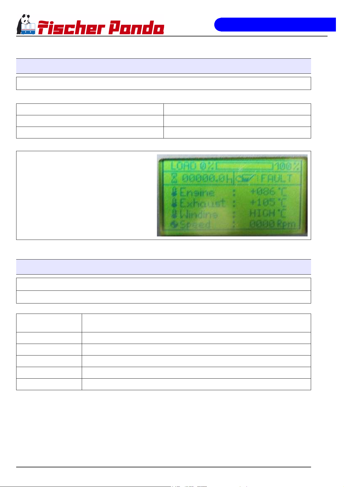
Fischer Panda Datasheet
A.6 Error warnings
Error warnings are shown in the display. The screen switch from the temperature to „High“.
Following warnigs are displayed
Engine temp. > 75 °C
Exhaust temp. > 70 °C
Winding temp. > 120 °C
Table 1: Warning table
Example for the warning on the display
(Winding temp. „HIGH“)
Panda iControl
Fig. A.6-1: Display warning (winding temp „high“) - example
A.7 Errors
The least 5 errors are stored in the electronic memory and can be read out by the service technican..
Push the „enter“ button to quitt errors which has stopped the generator
Unexpected stop Generator stops during operation or RPM droped under 1100 RPM (Fuel low, overload
ect.)
Fault: Oilpress Oilpressure to low
Fault: Winding Winding temp. over 135°C
Fault: Exhaust Exhaust tem over> 75°C (PMS version) or>100°C(vehicles versions)
Fault: Cyl. Head Cylinder head temp. over >90°C (PMS version) or >95°C (vehicles versions)
Starting Fail Generator do not start after 10 sec.
Table 2: Fault table
Page 88 - Chapter A: Panda iControl Panel_iControl_eng.fm
Page 89
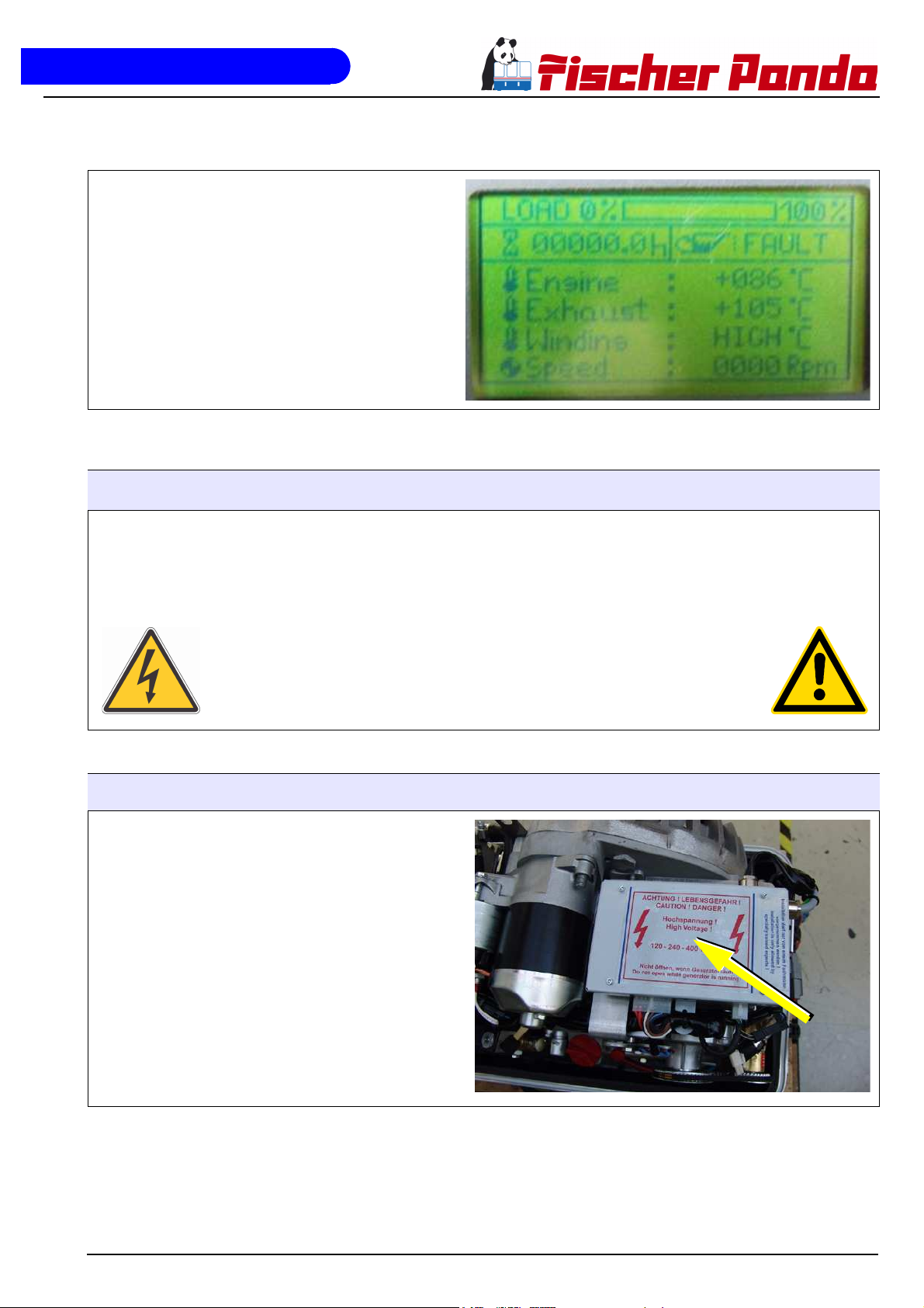
Panda iControl
Example for an error display after the generator was
stopped.
(Oil Pressure failed)
A.8 Electronic board
Fischer Panda Datasheet
Fig. A.7-1: Display warning (oil pressure failed) - example
The iControl panel has an electronic board which is mounted at the Generator. This board controls all generator
functions.
The bord is in a box and contains self healing fuses and relais.
For safety reasons it is not allowed to open the box of the electronic board.
Inside there are up to450VAC. !!!DANGER TO LIFE.
Only special trained persons are allowed to change the board in case of an
error.
A.8.1 Location at the Panda i-series generator
Electronic board at the Panda 4000i PMS.
The location of the electronic board is depended on
the generator type and can vary.
Fig. A.8.1-1: Location of the electronic board
Panel_iControl_eng.fm Chapter A: Panda iControl - Page 89
Page 90
Panda iControl
Fischer Panda Datasheet
A.9 Technical data
A.9.1 Intended use
The Panda iControl is a part of the Panda i-series generator. It is not allowed to use the iControl at other generators or applications.
The iControl must be connected with the electronic board at the generator.
Attention! See also the safety instructions in the generator and the PMGi manual. The
rules of the respective regional authority must be adhered to. Only an electrician may
carry out installation of the electrical connections for safety reasons.
Page 90 - Chapter A: Panda iControl Panel_iControl_eng.fm
Page 91
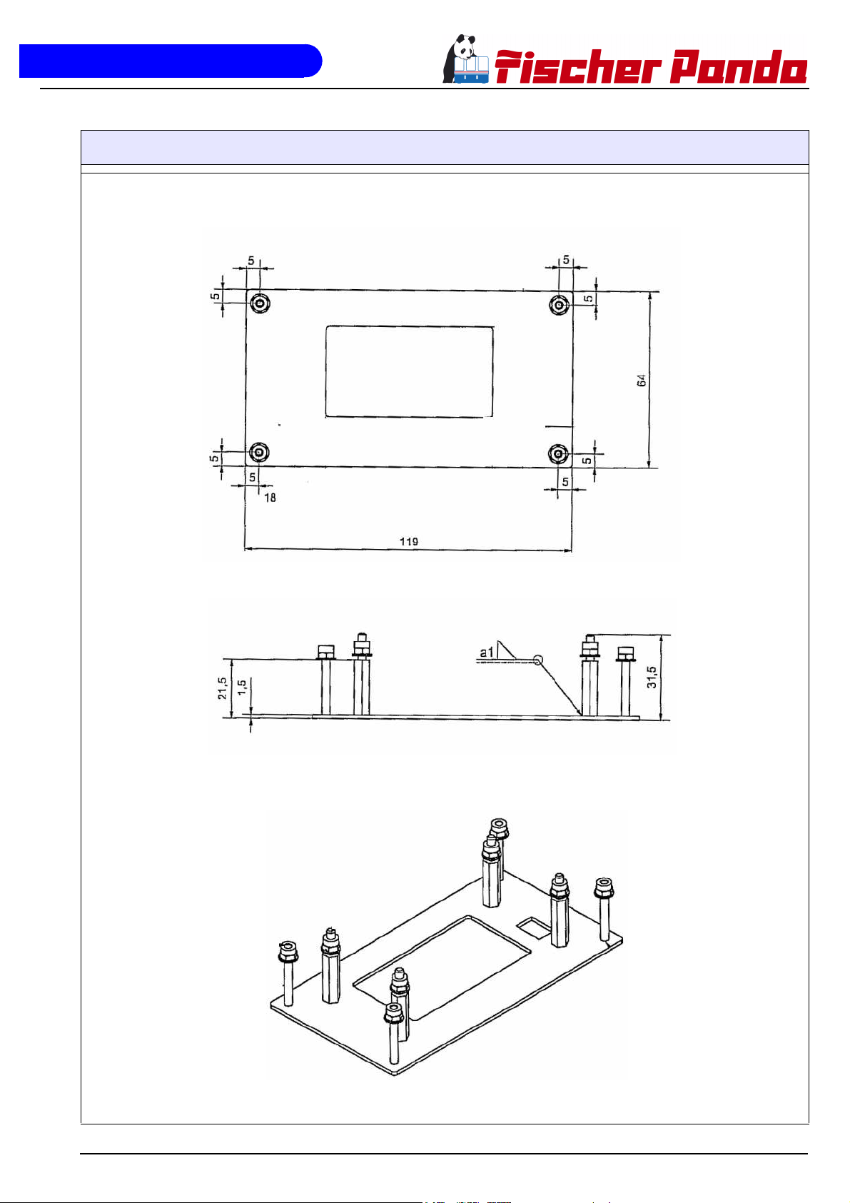
Panda iControl
A.9.2 Dimensions
Fig. A.9.2-1: Dimensions
Panel_iControl_eng.fm Chapter A: Panda iControl - Page 91
Page 92

Panda iControl
Intentionally Blank
Page 92 - Chapter A: Panda iControl Panel_iControl_eng.fm
Page 93
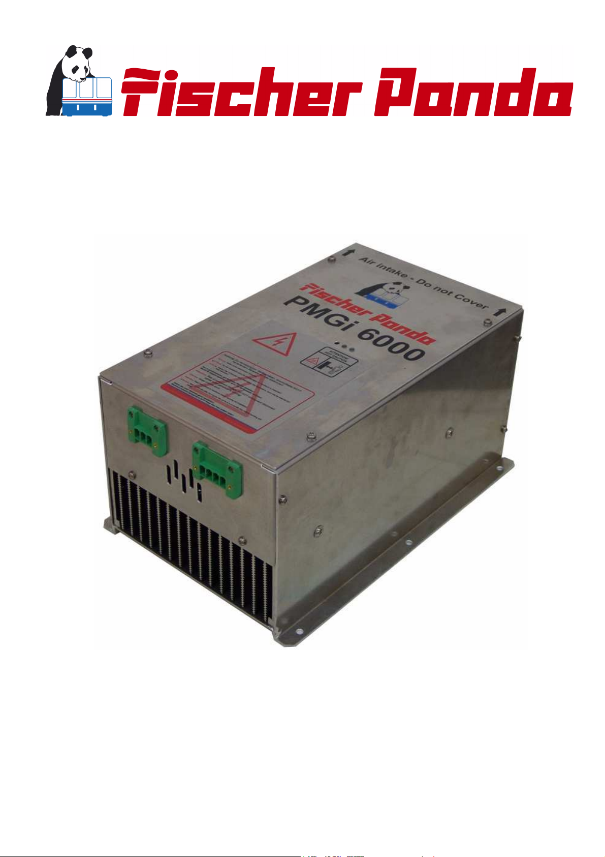
Panda i-series
Part 3: PMGi 6000 inverter Manual
PMGi 6000
Fischer Panda GmbH
Panda_PMGi_6000_eng.R0116.1.09
Page 94
Current revision status
Document
Actual: Panda_PMGi_6000_eng.R01_16.1.09
Replace:
Revision Page
94
Page 95
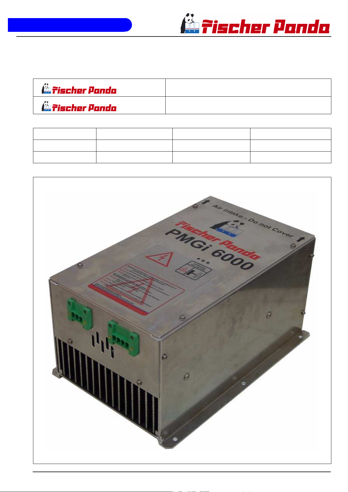
Panda PMGi 6000
A. Panda PMGi 6000
Fischer Panda Datasheet
Document Hardware Software
Actual: R01
Replace:
Art Nr.
Bez.
.
21.07.03.008P
Panda PMGi 6000
PGMi 6000_eng.fm Chapter A: Panda PMGi 6000 - Page 95
Page 96
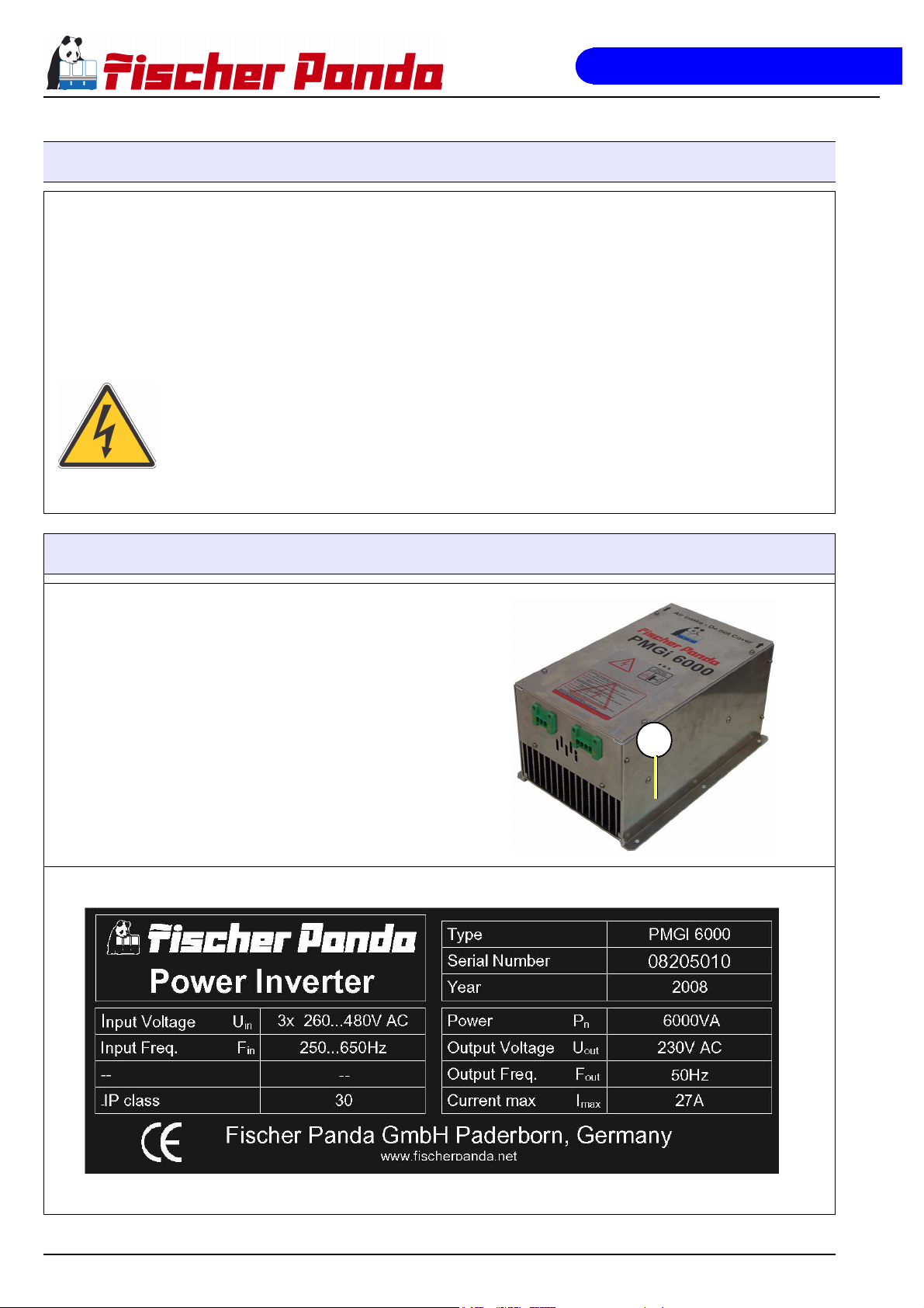
Panda PMGi 6000
1
Fischer Panda Datasheet
A.1 Safety instruction
The generator may not be taken into use with the cover removed.
The rotating parts (belt-pulley, belts, etc) must be covered and protected so that there is no danger to life and
body!
If a sound insulation cover must be produced at the place of installation, then well-placed signs must show that
the generator can only be switched on with a closed capsule.
All servicing-, maintenance or repair work may only be carried out, when the motor is not running.
Electrical power: DANGER TO LIVE!
Electrical voltages above 48 volts (battery chargers greater than 36 volts) are always dangerous
to life). The rules of the respective regional authority must be adhered to. Only an electrician
may carry out installation of the electrical connections for safety reasons.
Before start working at the Panda i-series Generator (service, repair ect), diconnect the starter
battery (First minus cable, then positive cable). This avoid unexpected start of the generator.
A.2 Type plate
1. Location of the type plate
Fig. A.2-1: Type plate
Page 96 - Chapter A: Panda PMGi 6000 PGMi 6000_eng.fm
Page 97
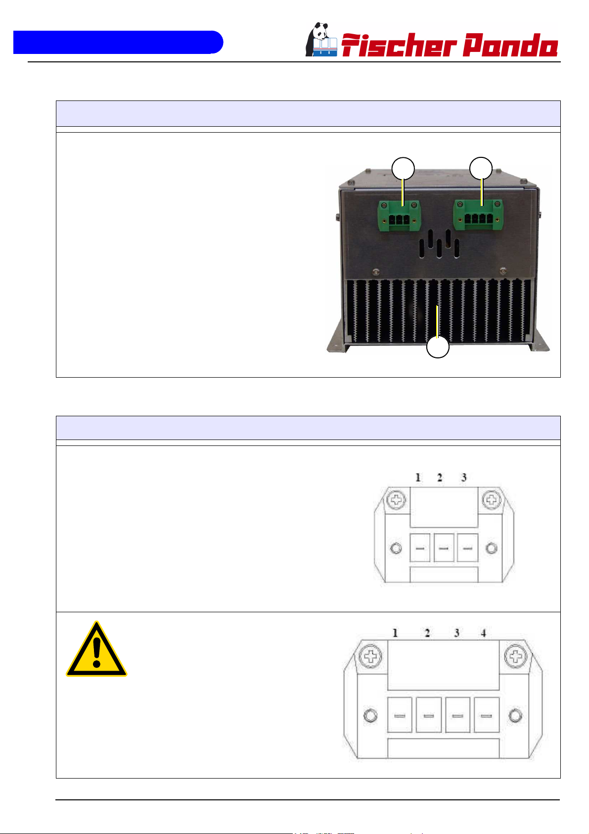
Panda PMGi 6000
3
1
2
A.3 Front side/connection side
To connect the PMGi 6000 use the prepared cable with t
he 4pin plug and connect to socket 3 (PMGi in-450V/
400Hz)
Connect your termination box with the socket 1. Use a
3pin plug (230V/50Hz AC - PMGi out)
Do not cover the Air out grille (2)
Fischer Panda Datasheet
A.3.1 Socket pins of the PMGi 6000
Socket 1 - 230V / 50Hz AC - PMGi out
1. Ground (cabel green/yellow)
2. Neutral (cabel blue)
3. Live (cabel brown)
.Socket 3 - PMGi in
1. Ground
2-4. Phase 1-3
Fig. A.3-1: Connection side
Attention! Connecting one of the three Phase with the
earth pin will destroy the PGMi
Fig. A.3-1: Sockets
PGMi 6000_eng.fm Chapter A: Panda PMGi 6000 - Page 97
Page 98
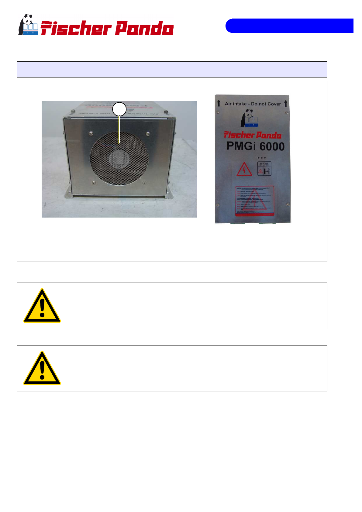
Fischer Panda Datasheet
1
A.4 Back side - Top side
Panda PMGi 6000
Inside of the PMGi a fan is mounted. The air holes and air grille should not be covered.
01. Air holes
Fig. A.4-1: Back side
Attention! Inside of the PMGi are up to 550VAC. The cover of the PMGi should only be
opened by special trained persons !!! Danger for Live“
Attention!
Make sure that the connection between the generater and the PMGi is secured. Never
connect or disconnect the PMGi while the generator is running. This will destroy the PMGi
(it may burn or explode).
Page 98 - Chapter A: Panda PMGi 6000 PGMi 6000_eng.fm
Page 99
Panda PMGi 6000
A.5 Operation manual
A.5.1 Primary remarks / Winter operation
The PGMi can operate in the range of -20°C to +40°C .
A.5.2 Load at the PMGi
Do not overload the PMGi. It will go on error.
A.5.3 Automatic start
Fischer Panda Datasheet
The generator can start (depending on the remote control panel) by an external signal (atomatic start)
If you use this option make sure that the load is connected to the PMGi after the output has reached the nominal
230V / 50Hz and not to overload the PMGi (some electronic devices, such like air conditions, need an higher start
current). May use a relay which connect the load at 230V.
A.6 Status LED´s
When the PMGi is mounted on the right way, vertical with the lectric connection down. The LED´s from left to right
are:
Red - Yellow - Green
LED - Red Red LED lights together with the green LED for the very first seconds (about 5 sec) after the
running of the engine. During this time no output is provided by the PMGi.
Red LED starts to blink when an overload condition is reched. During this time the green LED
continiues to light.
When an overload condition stays for too much time the red LED stops blinking and stays per-
manently switched on, while the green LED switch off.
LED-Yellow Yellow LED lights together with the green LED when the output voltage becomes less than the
nominal voltage.
LED-Green Green LED permanently lights alone when the PMGi output is available and it value stays in
the spacification
Table 1: Status LED´s
PGMi 6000_eng.fm Chapter A: Panda PMGi 6000 - Page 99
Page 100
Panda PMGi 6000
Fischer Panda Datasheet
A.7 Cooling of the PMGi
Inside of the PMGi a fan is mounted.
Do not cover the air holes and grille.
The heat sink and the fan of the PMHGi may become dirty as a consequence of tzhe use of the generator, and so
the unit can loose a part of their heat transfer carateristic. Every 6 months it is necessary to visual inspect the heat
sinks and clean it with compressed air. At every Generator service the fan of the PMGi should be cleaned by the
special trained person.
A.8 Installation of the PMGi
The PMGi must be mounted vertical, with the electrical connection down. So you can read the writing on the
PMGi.
The surface where the PMGi is mounted should be smoothed and support the heat transfer. The Air holes and Air
grille must be not covered and enough cooling air must be pleasant at any time for the PMGi.
To mount the PMGi use the four fixing holes diameter 6,5mm.
Note! See the safety instruction in your Generator and iControl Manual.
The rules of the respective regional authority must be adhered to. Only an electrician may carry
out installation of the electrical connections for safety reasons.
A.8.1 Electrical connection.
Only special trained persons are allowed to make the electrical connection.
When an extension cable is required, be sure to use a though rubber sheated flexible and fireproof cable. Limit
length of extension cables depends on the voltage drop along the cable. This drop must be less than 2,5% value
of the nominal output voltage.
Pay attention to the right pin assignment. See “Socket pins of the PMGi 6000” on page 97.
Page 100 - Chapter A: Panda PMGi 6000 PGMi 6000_eng.fm
 Loading...