

Page 1
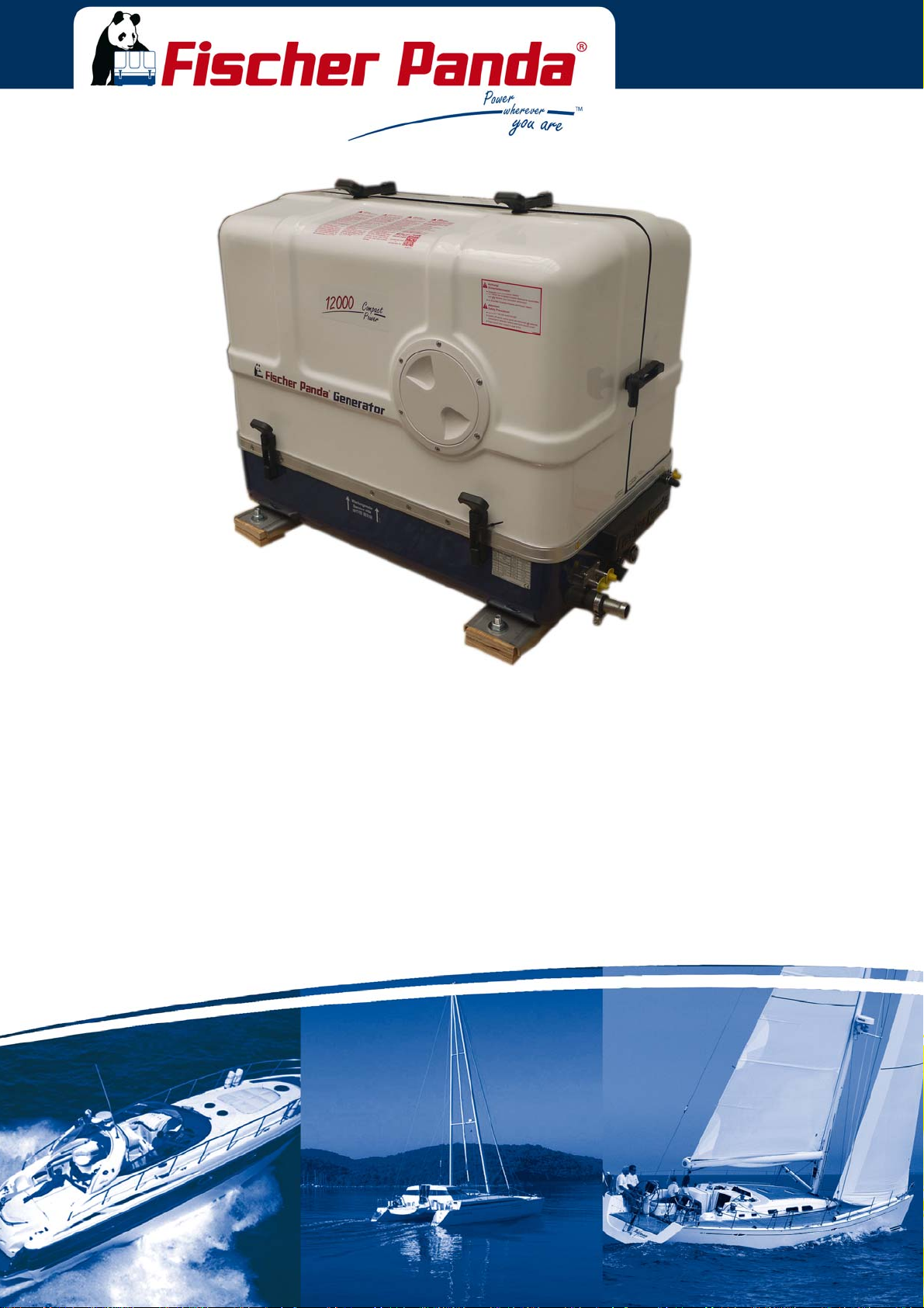
Manual marine generator
Panda 12000x PMS 12 kVA 230V - 50 Hz
Panda 15000x PMS 15 kVA 230V - 50 Hz
Super silent technology
Panda_12000-15000_xControl_PMS_eng.R01 18.12.15
Page 2
Current Revision Status
Document
Actual: Panda_12000-15000_xControl_PMS_eng.R01_18.12.15
Replaces:
Revision Page
Handbuch neu erstellt R01
Generatorbezeichnung auf dem Titel berichtigt.
Erstellt durch / created by
Fischer Panda GmbH - Leiter Technische Dokumentation
Otto-Hahn-Str. 32-34
33104 Paderborn - Germany
Tel.: +49 (0) 5254-9202-0
email: [email protected]
web: www.fischerpanda.de
Copyright
Duplication and change of the manual is permitted only in consultation with the manufacturer!
Fischer Panda GmbH, 33104 Paderborn, reserves all rights regarding text and graphics. Details are given to the
best of our knowledge. No liability is accepted for correctness. Technical modifications for improving the product
without previous notice may be undertaken without notice. Before installation, it must be ensured that the pictures,
diagrams and related material are applicable to the genset supplied. Enquiries must be made in case of doubt.
FischerPandaGmbH
Otto‐Hahn‐Str.40
D‐33104Paderborn
Germany
Tel.
Fax.
Hotline
Email
Web
:
+49(0)52549202‐0
:
+49(0)52549202‐550
:
+49(0)52549202‐767
:
:
www.fischerpanda.de
Page 3

Inhalt / Contens
Current Revision Status...................................... ... ... ... .... ... ... ... .... ... ... ... .... ... ... ... ... ..................................... ....... 2
1 General Instructions and Regulations.................................................................................................. ..... 12
1.1 Safety first!...................................................................................................................................... .... 12
1.2 Tools ............................... ....................................................................... ........................................ ..... 16
1.3 Manufacturer declaration in accordance with the Machinery Directive 2006/42/EC ...................... ..... 18
1.4 Customer registration and guarantee ............................................................................................. .... 18
1.4.1 Technical support ........................................................................................................... .... 18
1.4.2 Caution, important information for start-up! ............................... ..................................... .... 18
1.5 Safety Instructions - Safety First! ................................................................................................... ..... 19
1.5.1 Safe operation ................................................................................................................ .... 19
1.5.2 Observe safety instructions! ........................................................................................... .... 19
1.5.3 Personal protective clothing (PPE) ................................................................................. .... 19
1.5.4 Cleanliness ensures safety ............................................................................................. .... 19
1.5.5 Safe handling of fuels and lubricants .............................................................................. ..... 20
1.5.6 Exhaust fumes and fire protection .................................................................................. .... 20
1.5.7 Safety precautions against burns and battery explosions .............................................. ..... 21
1.5.8 Protect your hands and body from rotating parts! .......................................................... .... 21
1.5.9 Anti-freeze and disposal of fluids ............................................... .... ... ... ... .... ... ... ... ... .... ... . .... 21
1.5.10 Implementation of safety inspections and maintenance ................ ................................. ..... 22
1.6 Warning and instruction signs......................................................................................................... .... 22
1.6.1 Special instructions and hazards of generators ................................... ... .... ... ... ... ... ........ .... 22
1.6.1.1 Protective conductor and potential equalisation:......... ..................................... ..... 23
1.6.1.2 Protective conductor for Panda AC generators:............................................... .... 23
1.6.1.3 Switch off all loads while working on the generator ......................................... .... 23
1.6.1.4 Potential equalisation for Panda AGT DC generators...................................... .... 23
1.6.1.5 Safety instructions concerning cables.............................................................. ..... 24
1.6.2 Recommended starter battery sizes .... ... ... ... .... ... ... ... .... ... ... ... ... .... ... ... ... .... ... ... ... ... .... ... . .... 24
1.6.3 Important instructions for batteries - starter and/or traction batteries ............................. .... 24
1.6.4 General safety instructions for handling batteries .......................................................... .... 25
2 In case of Emergency First Aid / Im Notfall - Erste Hilfe................................ .... ................................. ..... 27
2.1 WHEN AN ADULT STOPS BREATHING .................... .......................................... .... ... ... ... ... .... ... . ..... 28
3 Basics ...................................................................................................................................................... ..... 29
3.1 Intended use of the machine .......................................................................................................... .... 29
3.2 Purpose of the manual and description of the definitions of the trained persons/operators/users. .... 29
3.2.1 Trained persons .............................................................................................................. .... 29
3.2.2 Operator ......................................................................................................................... .... 29
3.2.3 User ................................. ................................................................. .............................. .... 30
3.3 Components of the xGenerator ...................................................................................................... .... 30
3.4 Range of operation......................................................................................................................... .... 32
3.5 Panda transport box ....................................................................................................................... .... 32
3.5.1 Bolted Fischer Panda transport box ................................. ... ... ... ..................................... .... 32
3.5.2 Fischer Panda transport box with metal tab closure ....................................................... .... 32
3.6 Opening the MPL sound insulation capsule ................................................................................... .... 33
3.6.1 Opening the GFK sound insulation capsule ........................ ... ... ..................................... .... 34
3.7 Transport and loading/unloading................................................................................................... . .... 34
3.7.1 Transporting the generator ............................................................................................. .... 34
3.7.2 Loading/unloading of the generator ..... ... ... ... .............................................. ... ... ... ... .... ... . .... 34
18.12.15 Inhalt/Contens Seite/Page 3
Page 4

Inhalt / Contens
3.8 Special service instructions and measures for extended machine downtimes and decommissioning 35
3.8.1 Instructions for the starter battery for extended downtimes ................. .... ... ... ... .... ... ... ... . .... 35
3.8.2 Measures for short downtimes ................................ ................. ................ ................ ....... .... 36
3.8.3 Measures for medium term downtimes / hibernation ............................... ....................... .... 36
3.8.3.1 Courses for preservation: ................................................................................. .... 36
3.8.3.2 Measures for removing surface protection after medium term downtimes (3 to 6
months). 37
3.8.4 Measures for extended downtimes / decommissioning .................................................. .... 37
3.8.4.1 Courses for preservation: ................................................................................. .... 37
3.8.4.2 Measures for removing surface protection after extended downtimes / recommissioning
(over 6 months): 38
4 The Panda Generator.............................................................................................................................. ..... 39
4.1 Type plate at the Generator............................................................................................................ .... 39
4.2 Description of the Generator........................................................................................................... .... 40
4.2.1 Right Side View .............................................................................................................. .... 40
4.2.2 Left Side View ................................................................................................................. .....41
4.2.3 Font View ........................................................................................................................ ..... 42
4.2.4 Back View ....................................................................................................................... .....43
4.2.5 View from above ............................................................................................................. ..... 44
4.3 Details of functional units ....................................... ... .... ... .......................................... ... ................. ..... 45
4.3.1 xControl panel ................................................................................................................. .... 45
4.3.2 The Cooling System - Schema ....................................................................................... .....46
4.3.3 The Fuel System - Schema ............................................................................................ .....47
4.3.4 The operation surveillance system ................................................................................. .....48
4.3.5 The Oil Circuit - Schema ................................................................................................. .....50
4.4 Remote Control Panel - see separate Control Panel Manual......................................................... .... 50
4.4.1 Starting the Generator - see separate Control Panel Manual ......................................... .... 50
4.4.2 Stopping the Generator - see separate Control Panel Manual ................... .................... .... 50
5 Generator operation instruction............................................................................................................ .....51
5.1 Personal requirements......... ... ... ... .... ... ... ... .... .......................................... ... .................................... .... 51
5.2 Hazard notes for the operation ....................................................................................................... .... 51
5.3 General operating instruction.......................................................................................................... .... 51
5.3.1 Operation at low temperatures ....................................................................................... .... 51
5.3.1.1 Pre-heating the diesel motor ............................................................................ .... 52
5.3.1.2 Tips regarding starter battery ........................................................................... .... 52
5.3.2 Light load operation and engine idle ............................................................................... .... 52
5.3.2.1 The soot of the generator is due to the fact that:.............................................. .... 52
5.3.2.2 To prevent the soot of the generator following steps should be observed:...... .... 52
5.3.3 Generator load for a longer period and overload ............................................................ .... 52
5.3.4 Protection conductor: ...................................................................................................... .... 53
5.3.5 Operating control system on the Fischer Panda generator ............................................ .... 53
5.4 Instructions for capacitors - not present at all models..................................................................... .... 53
5.5 Checks before start - see remote control panel data sheet ............................................................ ....53
5.6 Starting the generator - see remote control panel data sheet......................................................... .... 54
5.7 Stopping the generator - see remote control panel data sheet....................................................... ....54
6 Installation Instructions.......................................................................................................................... .....55
6.1 Personal requirements......... ... ... ... .... ... ... ... .... .......................................... ... .................................... .... 55
6.1.1 Hazard notes for the installation .......................... ... .... ... ... ... .... ... ... ... ... .... ... ... ... .... ... ... ... . .... 55
Seite/Page 4 Inhalt/Contens 18.12.15
Page 5

Inhalt / Contens
6.2 Place of installation.............................................................................................................. ........... .... 5 6
6.2.1 Preliminary remark ......................................................................................................... .... 56
6.2.2 Preparing the base - placement ..................................................................................... .... 57
6.2.3 Advice for optimal sound insulation ................................................................................ .... 57
6.3 Generator Connections.............. ... ... .... .......................................... ... ... ... ... .... ................................. .... 57
6.4 Installation of the cooling system - raw water................................................................................. .... 58
6.4.1 General information ........................................................................................................ .... 58
6.4.2 Fischer Panda installation kit - raw water ....................................................................... .... 58
6.4.3 Installation of the through hull fitting in Yachts - scheme ............................................... .... 60
6.4.4 Quality of the raw water sucking in line .......................................................................... .... 60
6.4.5 Generator installation above waterline ...................... .... ... ... ... ... .... ... ... ... .... .................... .... 60
6.4.5.1 Raw water installation scheme......................................................................... ..... 62
6.4.6 Generator installation below waterline ............................................................................ .... 63
6.4.6.1 Raw water installation scheme......................................................................... ..... 64
6.5 Installation of the cooling system - fresh water............................................................................... ... . 65
6.5.1 Position of the external cooling water expansion tank .................................................... .... 65
6.5.2 Scheme for freshwater circuit at two circuit cooling system ........................................... ..... 66
6.6 Ventilation of the coolant circuit / freshwater .................................................................................. .... 66
6.6.1 Pressure Test for Controlling the Cooling Water Circuit ................................................. .... 68
6.7 Installation of the water cooled exhaust system ............................................................................ ..... 69
6.7.1 Fischer Panda installation kit - Exhaust System ............................................................. .... 69
6.7.2 Installation of the standard exhaust system ................................................................... .... 70
6.8 .Installation of the waterlock ........................................................................................................... .... 71
6.8.1 Possible cause for water in the exhaust hose ................................................................ .... 72
6.8.1.1 Possible cause: exhaust hose...................................................... ... ... ... ... .... ... . .... 72
6.8.1.2 Possible cause: cooling water hose...................................................... ... .... ... . .... 72
6.8.2 Installation area of the waterlock .................................................................................... .... 72
6.8.3 The volume of the waterlock ................... ... ... .... ... ... ... ..................................................... .... 73
6.8.3.1 Ideal position of the waterlock............................... ... ... .... ... ... ... .... ... ... ... ... .... .... ..... 75
6.8.3.2 Example of the installation of the waterlock off-center and possible effects:... ..... 78
6.9 Exhaust / water separator............................................................................................................... .... 81
6.9.1 Installation exhaust water separator ............................................................................... ..... 83
6.10 Installation of the water cooled exhaust system ............................................................................ ..... 84
6.10.1 Installation of the standard exhaust system ................................................................... .... 84
6.11 .Installation of the waterlock ........................................................................................................... .... 85
6.11.1 Possible cause for water in the exhaust hose ................................................................ .... 85
6.11.1.1 Possible cause: exhaust hose............... ... ... .... ... ... ... ... .... ... .............................. . ... 85
6.11.1.2 Possible cause: cooling water hose......................................................... .... ... . .... 85
6.11.2 Installation area of the waterlock .................................................................................... .... 86
6.11.3 The volume of the waterlock ......... ... .... ... ... ... .... ... ... ........................................................ .... 86
6.11.3.1 Ideal position of the waterlock............................... ... ... .... ... ... ........................... .... . 88
6.11.3.2 Example of the installation of the waterlock off-center and possible effects:... ..... 91
6.12 Exhaust / water separator............................................................................................................... .... 94
6.12.1 Installation exhaust water separator ............................................................................... ..... 96
6.13 Fuel system installation .......................................................... ... .... ... ... ... ... ..................................... .... 97
6.13.1 Fischer Panda installation kit - Fuel system ................................................................... .... 97
6.13.1.1 The following items need to be installed: ......................................................... .... 99
6.13.2 Connection of the fuel lines at the tank .......................................................................... .. 101
6.13.3 Position of the pre-filter with water separator ................................................................. ... 102
18.12.15 Inhalt/Contens Seite/Page 5
Page 6

Inhalt / Contens
6.13.4 Ventilating air from the fuel system ................................................................................. .. 102
6.14 Generator DC system installation ................................................................................................... .. 102
6.14.1 Connection of the starter battery block ........................................................................... .. 102
6.14.2 How to connect two 12 V batteries to a 24 V battery bank ...................................... ... ... . .. 106
6.14.3 Connection of the xControl panel - see separate xControl manual ................................ .. 107
6.15 Generator AC System Installation................................................................................................... .. 107
6.16 AC-Control box with VCS and starting current limitation................................................................. ..107
6.16.1 Installation with looped-in AC-Control box ...................................................................... .. 108
6.16.2 Installation AC-Box / Distribution panel connected separately ....................................... .. 109
6.16.3 Electronic voltage control xControl ................................................................................. .. 110
6.16.4 Connection to the AC on-board power supply ................................................................ .. 110
6.16.4.1 Protective conductor......................................................................................... .. 110
6.16.4.2 Electrical fuse................................................................................................... .. 110
6.16.4.3 Required cable crosssections ......................... ... ... .... ... .................................... .. 110
6.16.4.4 Disconnector - power source selector (three way cam switch) . ... ... ... .... ... ... ... . .. 110
6.17 Special recommendations............................................................................................................... .. 111
6.18 Instructions on prevention of galvanic corrosion............................................................................. .. 111
6.18.1 Instructions and measures on prevention of galvanic corrosion . .................................... .. 111
6.19 Isolation test............................................ ... .... ... ... ... ... .... ................................................................. .. 112
6.20 Initial operation................................................................................................................................ .. 112
7 Maintenance Instructions....................................................................................................................... ... 113
7.1 Personal requirements......... ... ... ... .... ... ... ... .... .......................................... ... .................................... .. 113
7.2 Hazard notes for the maintenance.................................................................................................. .. 113
7.3 Environmental protection ................................................................................................................ .. 115
7.4 Maintenance interval....................................................................................................................... .. 115
7.5 General maintenance instructions .................................................................................................. .. 115
7.5.1 Checks before each start ........................... .... ... ... ... .... .......................................... ... ... ... . .. 115
7.5.2 Check of Hoses and rubber parts in the sound insulated capsule .................................. .. 115
7.6 Oil Change Intervals ....................................................................................................................... .. 116
7.7 Checking oil-level....... ... ... .... ... ... ... .... ... .......................................... ... .............................................. .. 116
7.7.1 Refilling Oil ........................ .......................................... ... ... .............................................. .. 117
7.7.2 After the oil level check and refilling the oil ..................................................................... .. 117
7.8 Replacement of engine oil and engine oil filter ............................................................................... .. 118
7.8.1 After the oil change ......................................................................................................... . . 120
7.9 Verifying the starter battery and (if necessary) the battery bank..................................................... .. 121
7.9.1 Battery ............................................................................................................................ .. 121
7.9.1.1 Check battery and cable connections .............................................................. .. 121
7.9.1.2 Check electrolyte level ....................................................... ... .... ... ... ................. .. 121
7.9.1.3 Check electrolyte density ................................................................................. .. 122
7.10 Grease lubricated generator backend bearing................................................................................ .. 122
7.10.1 Exchange of grease lubricated bearing .......................................................................... .. 123
7.10.1.1 Demounting the cooling disc (if existent).......................................................... .. 124
7.10.1.2 Demounting the backend bearing ...................... ... .... ... ... ... .............................. .. 124
7.10.1.3 Installing the new backend bearing................................. ... .............................. . . 125
7.11 Checking the oil level of the generator end bearing at Fischer Panda generators ......................... ..128
7.11.1 Oil level check ......... ... ... .......................................... .... ... ................................................. .. 129
7.11.2 Refilling oil ................................. .......................................... .... ... .................................... . . 129
Seite/Page 6 Inhalt/Contens 18.12.15
Page 7

Inhalt / Contens
7.11.3 Refiller-Set ....................... ................................. ................................... ........................... .. 130
7.11.4 Screw plug ...................................................................................................................... .. 130
7.12 Replacement of the oil-cooled backend bearing ............................................................................ ... 131
7.12.1 Exchange oil-cooled bearing .......................................................................................... .. 131
7.12.2 Demounting the bearing ................................................................................................. .. 131
7.13 Ventilating the fuel system.............................................................................................................. .. 143
7.13.1 Replacement of the fuel filter .......................................................................................... .. 144
7.13.1.1 Optional fuel filter with sight glass.................................................................... .. 145
7.14 Checking the water separator in the fuel supply ...............................................................................147
7.14.1 Replace the air filter mat ................................... ... ... ... .... ... ... ........................................... .. 147
7.14.2 Alternative replacement of the air filter mat with pull out holder ..................................... .. 148
7.14.3 Alternative replacement of the air filter at housing with snap fasteners ......................... ... 150
7.14.4 Ventilation of the coolant circuit / freshwater .................................................................. .. 151
7.14.5 V-belt replacement for the internal cooling water pump ................................................. .. 153
7.15 The raw water circuit................................................................................................................... .... .. 154
7.15.1 Clean raw water filter ...................................................................................................... .. 154
7.16 Causes with frequent impeller waste.............................................................................................. .. 155
7.16.1 Replacement of the impeller ... ... ... ... .... ... ........................................................................ ...156
7.17 Check and discharge the capacitors............................................................................................... .. 157
7.17.1 Replacing the Electric Starter ......................................................................................... .. 159
7.18 Replacing the DC Alternator .......................................................................................................... ... 162
7.19 Replacing the Oil Pressure Switch ................................................................................................ ... 166
7.19.1 Replacing the oil pressure sensor (optional component) ............................................... ... 167
7.20 Replacing the Injection Nozzles ..................................................................................................... ... 168
7.21 Checking the Flame Glow Plug (optional unit) ..................................................................................171
7.21.1 Replacing the Flame Glow Plug ..................................................................................... ... 172
7.22 Replacing the Glow Plugs .............................................................................................................. ... 173
8 Generator Faults ..................................................................................................................................... ... 175
8.1 Personal requirements.................................................................................................................... .. 175
8.2 Hazard notes for the troubleshooting............................................................................................. . .. 175
8.3 Tools and Measuring Instruments ................................................................................................. ... 177
8.4 Troubleshooting Table and Flowchart ........................................................................................... ... 178
8.4.1 Generator output voltage too low ................................................................................... .. 178
8.4.2 Generator voltage too high (more than 240 V - 50 Hz .................................................... .. 178
8.4.3 Generator voltage fluctuates .......................................................................................... .. 178
8.4.4 Generator not able to start electric motor ....................................................................... .. 178
8.4.5 Diesel motor fails to start ................................................................................................ .. 178
8.4.6 Starter is turning motor, but fails to start ......................................................................... .. 178
8.4.7 Motor does not achieve enough speed during starting process .................... ................. .. 180
8.4.8 Motor runs unsteady ......................................................................................................... 180
8.4.9 Motor speed drops .......................................................................................................... .. 180
8.4.10 Motor runs in off position ................................................................................................ .. 180
8.4.11 Motor stops by itself ............................. ... .......................................... ... ... .... ... ... ... ... ........ .. 180
8.4.12 Sooty, black exhaust .............................................................................. .... ... ................. .. 181
8.4.13 Generator must be shut off immediately if: ..................................................................... .. 181
8.5 Versions of the generator power terminal box ............................................................................... ... 182
18.12.15 Inhalt/Contens Seite/Page 7
Page 8

Inhalt / Contens
8.6 Overloading the generator ......... ... .... ... ... ... .... .......................................... ... ... ... ... .... ... ... ... .............. .. 186
8.6.1 Monitoring the Generator Voltage ................................................................................... ... 187
8.6.2 Automatic voltage monitoring and auto-shut down ......................................................... .. 187
8.7 Generator-Output Voltage is too low .............................................................................................. ... 188
8.7.1 Check and discharge the capacitors .............. ... .......................................... .................... .. 188
8.7.2 Checking the Capacitors ................................................................................................. ...190
8.7.2.1 Checking the electrical connections to the capacitors...................................... .. 190
8.7.3 Check the Generator Voltage ......................................................................................... .. 190
8.7.4 Measuring the Ohm Resistance of the Generator Windings .......................................... .. 191
8.7.5 Check the Windings for Short circuit .............................................. ... ... .... ....................... .. 191
8.7.6 Measuring the Inductive Resistance ............................................................................... ... 192
8.8 Generator provides no voltage........................................................................................................ .. 192
8.8.1 Rotor Magnetism Loss and „Re-magnetising“ ................................................................ .. 192
8.9 Engine Starting Problems .............................................................................................................. ... 193
8.9.1 Lifting solenoid for motor stop - optional ......................................................................... .. 193
9 Tables....................................................................................................................................................... ... 195
9.1 Technical Data................................................................................................................................ .. 195
9.2 Rated current .................................................................................................................................. .. 200
9.3 Cable cross section.... .......................................... ... ... .......................................... .... ... .................... .. 200
9.4 Fuel................................................................................................................................................. .. 201
9.5 Engine oil ........................................................................................................................................ .. 201
9.5.1 Engine oil classification ........... ... .... ... ... ... ... .... ... .......................................... ... ................. .. 201
9.5.1.1 Operating range: .............................................................................................. .. 201
9.5.1.2 Quality of oil:..................................................................................................... .. 201
9.6 Coolant specifications..................................................................................................................... .. 202
9.6.1 Coolant mixture ratio ....................................................................................................... .. 202
9.7 Types of coil ................................................................................................................................... ...203
9.7.1 HP1 - 230V / 50 Hz ........................................................................................................ .. 203
9.7.2 HP2 - 120V / 60 Hz ........................................................................................................ .. 203
9.7.3 HP2 - 120V / 60 Hz - Duo .............................................................................................. .. 204
9.7.4 HP3 - 400V / 50 Hz ......................................................................................................... .. 204
9.7.5 HP2 - 120V / 60 Hz ......................................................................................................... .. 204
9.7.6 DVS - 400V / 50 Hz .......................................................................................................... 205
9.7.7 DVS - 120V 240V / 60 Hz .............................................................................................. .. 205
9.8 Resistor & inductance of the generator coil ... ... ... ... ... .... ... ... ... .... ... ... ... .... ... ... ... ... ........................... .. 205
9.9 Voltage values stator coil................................................................................................................ .. 206
9.10 Diameter of conduits ....................................................................................................................... .. 207
9.11 ........................................................................................................................................................ .. 207
Current revision status................................................................................................................................ ... 210
10 Safety Instructions Panda xControl ...................................................................................................... ...211
10.1 Personal requirements.................................................................................................................... .. 211
10.2 Safety instructions................................................................ ... .... ... ... ... .... ....................................... .. 211
11 Panda xControl........................................................................................................................................ ...213
11.1 Components of the xControl ........................................................................................................... .. 213
11.1.1 xControl – CP-G ............................................................................................................. .. 213
Seite/Page 8 Inhalt/Contens 18.12.15
Page 9

Inhalt / Contens
11.1.2 xControl – GC-S ............................................................................................................ .. 213
11.1.3 xControl - CB-G ................................................... ... ... .... ... ... ... ... .... ... .............................. .. 214
11.2 Installation............................................................................................................................ ........... .. 214
11.2.1 Installation of the Electronic Control Unit (ECU) xControl - GC-S .................................. .. 214
11.2.2 Installation of the Connection Box xControl - CB-G ....................................................... .. 214
11.2.3 Installation of the xControl - CP-G .................................................................................. .. 214
11.3 Operation ........ ............................................................................................................................... ... 216
11.3.1 Switching on the generator .. ... ... ... ... .... ... ........................................................................ .. 216
11.3.1.1 Overview screen with activated autostart......................................................... .. 217
11.3.2 The Overview Screens ................................................................................................... ... 219
11.3.3 Overview Screens Symbolic ........................................................................................... .. 219
11.3.4 Overview Screens English Text ...................................................................................... .. 220
11.3.5 Overview Screens German Text .................................................................................... .. 221
11.4 Start of the Generator .................................................................................................................... ... 223
11.4.1 Marine version starting preparation / Checks (daily) ...................................................... .. 223
11.4.2 Vehicle version starting preparation / Checks (daily) ..................................................... .. 223
11.4.3 Starting the generator ..................................................................................................... .. 224
11.4.4 Stopping the generator ..................................................................................................... 225
11.5 The Menu .. ... ... ... ... .... ... ... .......................................... ..................................................................... ... 227
11.5.1 Main Menu ...................................................................................................................... .. 227
11.5.2 Submenu „Panel“ ............................................................................................................ .. 228
11.5.3 Submenu „Generator“ ..................................................................................................... .. 228
11.5.3.1 Set up the brightness of the CP-G ................................................................... .. 228
11.5.3.2 Set up the contrast of the CP-G....................................................................... .. 229
11.5.3.3 Set up the standby time out of the CP-G ......................................................... .. 229
11.5.3.4 Set up the standby brightness of the CP-G...................................................... .. 230
11.5.3.5 Set up the way of illustration of the overview screens of the CP-G ................. .. 230
11.5.3.6 Choose the language of the text screens of the CP-G..................................... .. 231
11.5.3.7 Set up temperature unit.................................................................................... .. 231
11.5.3.8 Reset all values of the panel submenu to standard ......................................... .. 232
11.5.3.9 Back to the main menu .................................................................................... .. 232
11.5.4 Submenu „Generator“ ..................................................................................................... .. 233
11.5.4.1 Set up the autostart of the CP-G...................................................................... .. 233
11.5.4.2 Set up the optional DC output of the CP-G...................................................... ... 235
11.5.4.3 Set up the operation mode for the opt. DC-Power (DP) output of the CP-G.... .. 236
11.5.4.4 Set up the follow-up time for the opt. DP output of the CP-G .......................... .. 236
11.5.4.5 Switch the outputs of the CP-G........................................................................ .. 236
11.5.4.6 Check the event log of the CP-G ..................................................................... .. 237
11.5.4.7 Reset all values of the generator submenu to standard................................... .. 237
11.5.4.8 Back to the main menu .................................................................................... .. 238
11.5.5 How to change the menu text from german to english ................................................... .. 238
11.6 Failure ................ ................................................. ............................................. .............................. ... 239
11.6.1 Symbols and Messages in the Display ........................................................................... .. 239
11.6.1.1 Message sample „Sensor defect“ ................................... ... ... ... .... ... ................. .. 239
11.6.1.2 Message sample sensor/cable broken............................................................. .. 239
11.6.1.3 Failure code ..................................................................................................... .. 240
11.6.2 Failuretable .......................... ................................... ................................ ........................ .. 240
11.6.3 Description of Symbols ......................................................................................................242
11.7 Technical Data ............................................................................................................................... ... 244
11.7.1 Technical Data of the CB-G ............................................................................................ .. 244
11.7.2 Technical Data of the CP-G ........................................................................................... .. 245
11.7.2.1 Dimension drawing:.......................................................................................... ... 247
18.12.15 Inhalt/Contens Seite/Page 9
Page 10

Inhalt / Contens
11.7.3 Technical Data of the GC-S ........................................................................................... ...248
11.8 ....................................................................................................................................................... ... 249
Seite/Page 10 Inhalt/Contens 18.12.15
Page 11

Dear Customer,
Thank you for purchasing a Fischer Panda Generator and ch oo sing Fisch er Panda as your p artne r for mobile powe r
on board. With your generator, you now have the means to produce your own power – wherever you are - and
experience even greater independence. Not only do you have a Fischer Panda generator on board, you also have
worldwide support from the Fischer Panda Team. Please take the time to read this and find how we can support you
further.
Installation Approval and Warranty
Every generator has a worldwide warranty. You can apply for this warranty through your dealer when the installation
is approved. If you have purchased an extended warranty, please ensure that it is kept in a safe place and that the
dealer has your current address. Consult your dealer about warranty options especially if you have purchased a
used generator. He will be able to advise about authorised Fischer Panda Services worldwide.
Service and Support
To ensure that your generator operates reliably, regular maintenance checks and tasks as specified in this manual
must be carried out. Fischer Panda can supply Service Kits which are ideal for regular servicing tasks. We only
supply the highest quality components which are guaranteed to be the RIGHT parts for your generator. Service
“Plus” Kits are also available and ideal for longer trips where more than one service interval may be required.
If you require assistance – please contact your Fischer Pan da Dealer. Please do not attempt to undertake any repair
work yourself, as this may affect your generator warranty. Your dealer will also be able to assist in finding your
nearest Fischer Panda service sta tio n. Your nearest service station can also be found in our Global Service Network
which can be downloaded from our homepage.
Product Registration
Please take the time to register your Fischer Panda Generator on our website at
http://www.fischerpanda.de/mypanda
By registering, you will ensure that you will be kept up to date on any technical upgrades or specific information on
the operation or servicing of your generator. We can even let you know about new Fischer Panda products –
especially helpful if you are planning to upgrade or expand your installation at a later date.
Fischer Panda Quality - Tried and Tested
DIN-certified according DIN ISO 9001
Thank you for purchasing a Fischer Panda Generator.
Your Fischer Panda Team
18.12.15 Kapitel/Chapter 1: - Seite/Page 9
Page 12
General Instructions and Regulations
1. General Instructions and Regulations
1.1 Safety first!
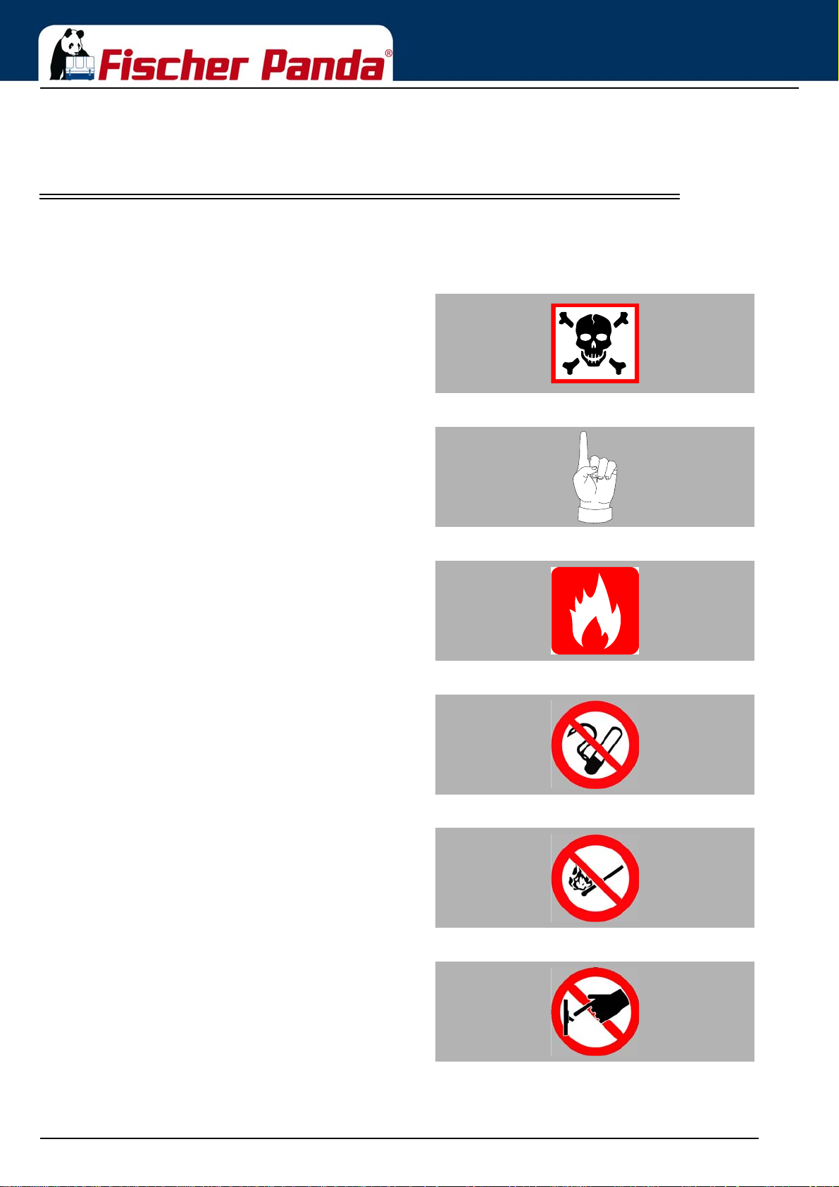
These symbols are used throughout this manual and on labels on the machine itself to warn of the possibility of
personal injury of lethal danger during certain maintenance work or operations. Read these instructions carefully.
WARNING: Hazardous materials Can cause acute or chronic health impairments or death
even in very small quantities if inhaled, swallowed, or
absorbed through the skin.
WARNING: Important information! This warning symbol draws attention to special warnings,
instructions or procedures which, if not strictly observed, may
result in damage or destruction of equipment.
ignition source (cigarettes, hot surfaces, sparks, etc.).
smoking is prohibited.
avoided.
is in progress.
WARNING: Fire hazard Warning of materials that may ignite in the presence of an
PROHIBITED: No smoking In the environment described / during the work specified,
PROHIBITED: No fire or naked light Fire and naked light are ignition sources that must be
PROHIBITED: Do not activate/start up The equipment shall not be activated or started up while work
Seite/Page 10 - Kaptitel/Chapter 1: General Instructions and Regulations 18.12.15
Page 13
General Instructions and Regulations
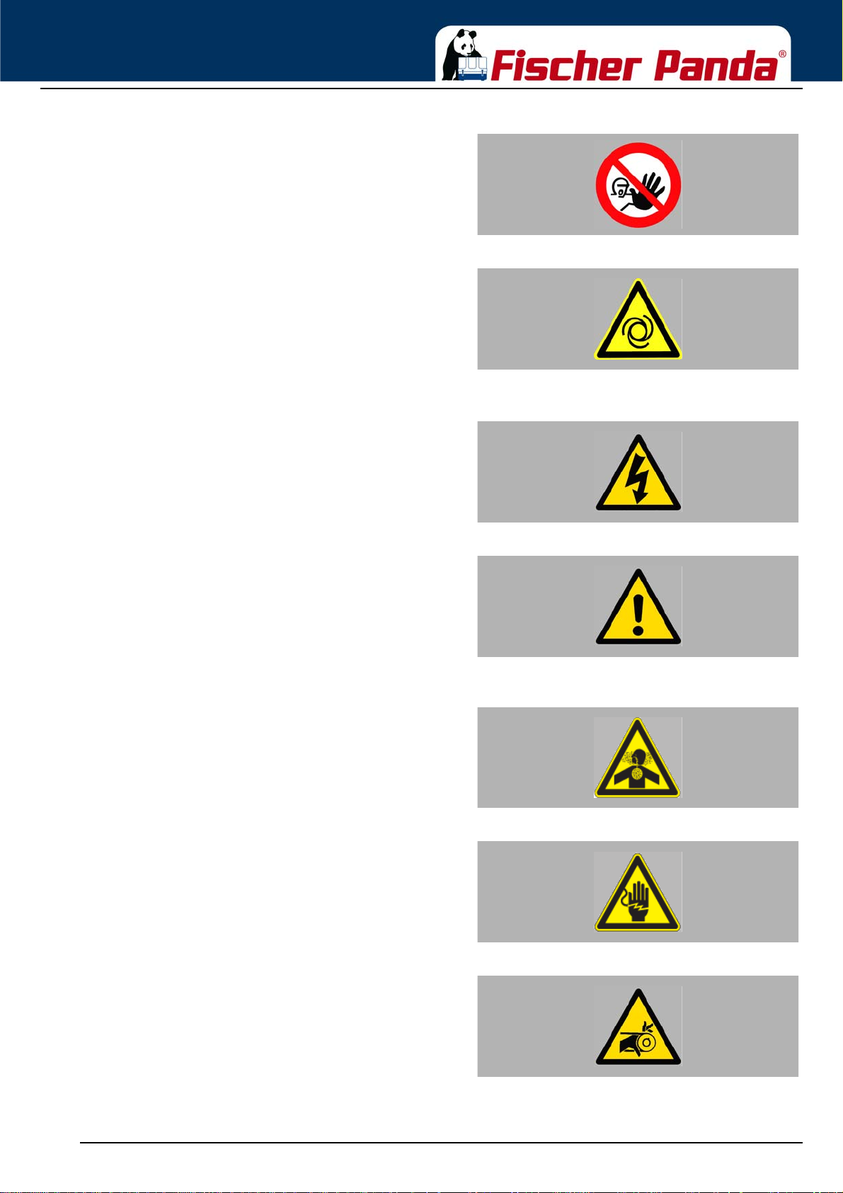
prohibited.
result in severe personal injury.
The generator can be equipped with a automatic st art device.
This means, an external signal may trigger an automatic
start-up. To avoid an unexpected starting of the generator,
the starter battery must be disconnected before working at
the generator.
draws attention to special warnings, instructions or
procedures which, if not strictly observed, may result in
severe personal injury or loss of life due to electric shock.
PROHIBITED: Do not touch Touchin g of the co rr es po nd in g parts and systems is
DANGER: Automatic start-up Danger for life! Working at a running generator can
WARNING: Hazardous electric voltage This danger symbol refers to the danger of electric shock and
Can cause acute or chronic health impairments or death
even in very small quantities if inhaled or ingested.
contact. Especially dangerous for persons with heart
problems or pacemakers.
WARNING: General warning General warning of a hazard area
WARNING: Danger due to inhalation and/or
ingestion
WARNING: Risk of electric shock upon contactWarning of live parts that may cause electric shock upon
WARNING: Danger due to rotating parts Danger of injury due to being pulled into equipment. Bruising
and torn off body p art s possible. Risk of b eing pulled i n when
touching with body part, loose-fitting clothing, scarf, tie, etc.
18.12.15 Kapitel/Chapter 1: General Instructions and Regulations - Seite/Page 11
Page 14
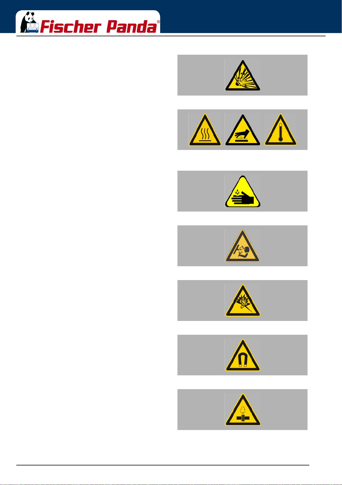
certain conditions, e.g. presence of heat or ignition sources.
General Instructions and Regulations
WARNING: Explosion hazard Warning of substances that may cause an explosion under
WARNING: Hot surface Warning of hot surfaces and liquids. Burn/scalding hazard.
Warning of substances that cause chemical burns upon
contact. These substances can act as contaminants if
introduced into the body.
abruptly and expel hot gases and fluids. Risk of injury due to
parts flying about, burn hazard due to liquids and gases.
WARNING: Danger due to corrosive substances,
potential contamination of person
WARNING: System may be pressurised! When the system is opened, the pressure can be relieved
WARNING: Hearing damageWarning of hearing damages.
WARNING: Magnetic fieldWarning of magnetic field.
WARNING: OverpressureWarning of overpressure.
Seite/Page 12 - Kaptitel/Chapter 1: General Instructions and Regulations 18.12.15
Page 15

General Instructions and Regulations
Wearing the applicable snugly fitting protective clothing
provides protection from hazards and can prevent damage to
your health.
Wearing hearing protection provides protection from acute
and gradual hearing loss.
Wearing safety goggles protects the eyes from damage.
Optical spectacles are not a replacement for the
corresponding safety goggles.
MANDATORY INSTRUCTION: Wear snugly fitting
protective clothing (PPE).
MANDATORY INSTRUCTION: Wear hearing
protection (PPE).
MANDATORY INSTRUCTION: Wear safety
goggles (PPE).
Wearing protective gloves provides the hands from hazards
like friction, graze, punctures or deep cuts and protects them
from contact with hot surfaces.
Compliance with the instructions in the manual can avert
danger and prevent accidents. This will protect you and the
generator.
Environmental protection saves our living environment. For
you and for your children.
MANDATORY INSTRUCTION: Wear protective
gloves (PPE).
MANDATORY INSTRUCTION: Observe the
instructions in the manual.
MANDATORY INSTRUCTION: Comply with
environmental protection requirements.
18.12.15 Kapitel/Chapter 1: General Instructions and Regulations - Seite/Page 13
Page 16
General Instructions and Regulations
1.2 Tools
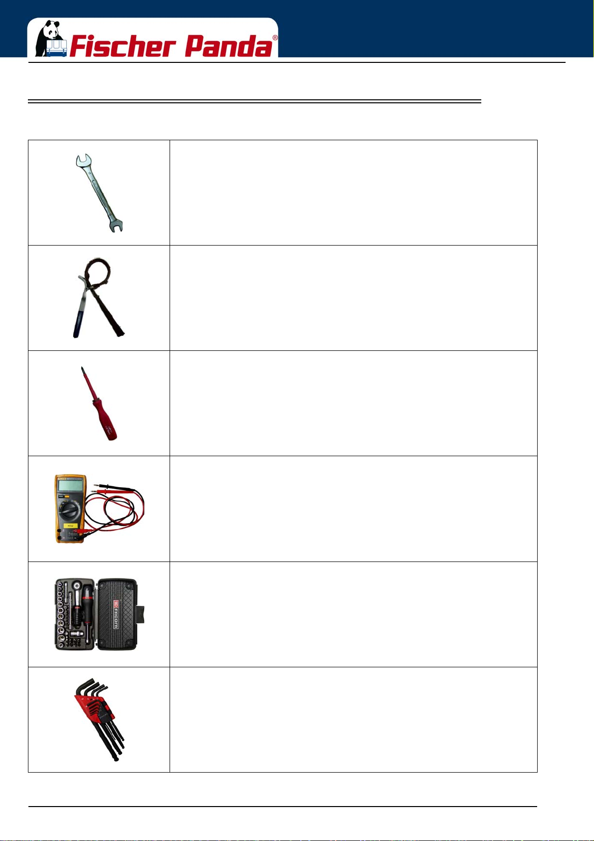
These symbols are used throughout this manual to show which tool must be used for maintenance or installation.
Spanners
W.A.F X = width across flats of X mm
Hook wrench for oil filter
Screw driver, for slotted head screws and for Phillips head screws
Multimeter, multimeter with capacitor measuring unit
Socket wrench set
Hexagon socket wrench set
Seite/Page 14 - Kaptitel/Chapter 1: General Instructions and Regulations 18.12.15
Page 17
General Instructions and Regulations
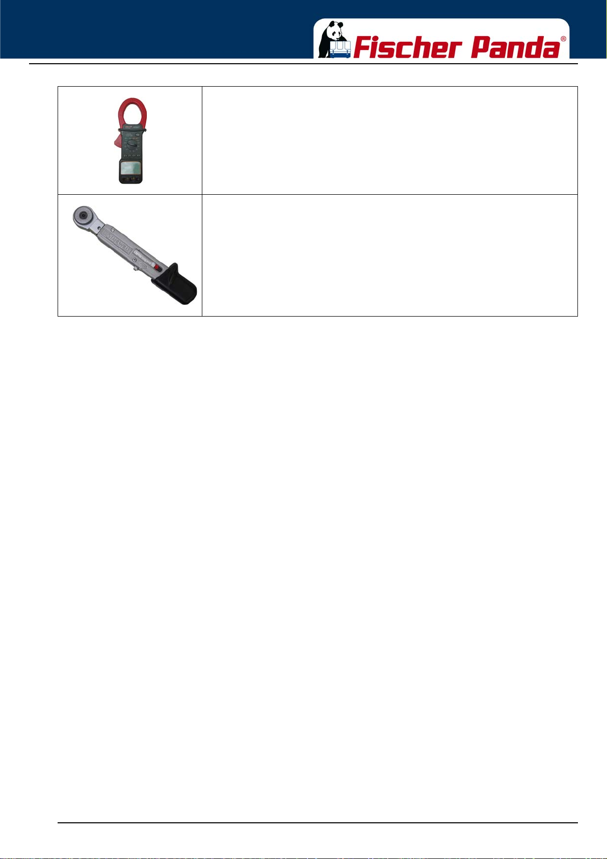
Clamp-on ammeter (DC for synchronous generators; AC for asynchronous
generators)
Torque wrench
18.12.15 Kapitel/Chapter 1: General Instructions and Regulations - Seite/Page 15
Page 18

General Instructions and Regulations
1.3 Manufacturer declaration in accordance with the Machinery Directive
2006/42/EC
Manufacturer declaration in accordance with the Machinery Directive 2006/42/EC
The generator was designed in such a way that all assemblies correspond with the CE guidelines. If Machinery
Directive 2006/42/EC is applied, then it is forbidden to start the generator until it has been ascertained that the
system into which the generator is to be integrated also complies with the Machinery Directive 2006/42/EC. This
includes the exhaust system, cooling system and electrical installations.
The evaluation of “protection agai nst contact“ must be carried out when installed, in conjunction with the respective
system. This also includes correct electrical connections, a safe ground wire connection, foreign body and humidity
protection, protection against moisture due to excessive condensation, as well as overheating through appropriate
and inappropriate use of the equipment in its installed state. The responsibility for implementing these measures lies
with those who undertake the installation of the generator in the final system.
1.4 Customer registration and guarantee
Use the advantages of registering your product:
• you will receive a Guarantee Certificate after approval of your installation data
• you will receive extended product information that may be relevant to safety.
• You will receive free upgrades as necessary.
Additional advantages:
Based on your complete data record, Fischer Panda technicians can provide you with fast assistance, since 90 % of
the disturbances result from defects in the periphery.
Problems due to installation errors can be recognized in advance.
1.4.1 Technical support
Techn ica l Suppor t via th e In ter n et: [email protected]
1.4.2 Caution, important information for start-up!
1. The commissioning log shall be filled in immediately after initial operation and shall be confirmed by signature.
2. The commissioning log must be received by Fischer Panda GmbH at Paderborn within 4 weeks of initial
operation.
3. After receiving the commissioning log, Fischer Panda will make out the official guarantee certificate and send it to
the customer.
4. If warranty claims are made, the document with the guarantee certification must be submitted.
If the above requirements are not or only partly fulfilled, the warranty claim shall become void.
Seite/Page 16 - Kaptitel/Chapter 1: General Instructions and Regulations 18.12.15
Page 19
General Instructions and Regulations
1.5 Safety Instructions - Safety First!
1.5.1 Safe operation
Careful handling of the equipment is the best insurance against an accident. Read the manual
diligently, and make sure you understand it before starting up the equipment. All operators,
regardless of their experience level, shall read this manual and additional pertinent manuals before
commissioning the equipment or installing an attachment. The owner shall be responsible for
ensuring that all operators receive this information and are instructed on safe handling practices.
1.5.2 Observe safety instructions!
Read and understand this manual and the safety instructions on the generator before trying to start up and operate
the generator. Learn the operating practices and ensure work safety. Familiarise yourself with the equipment and its
limits. Keep the generator in good condition.
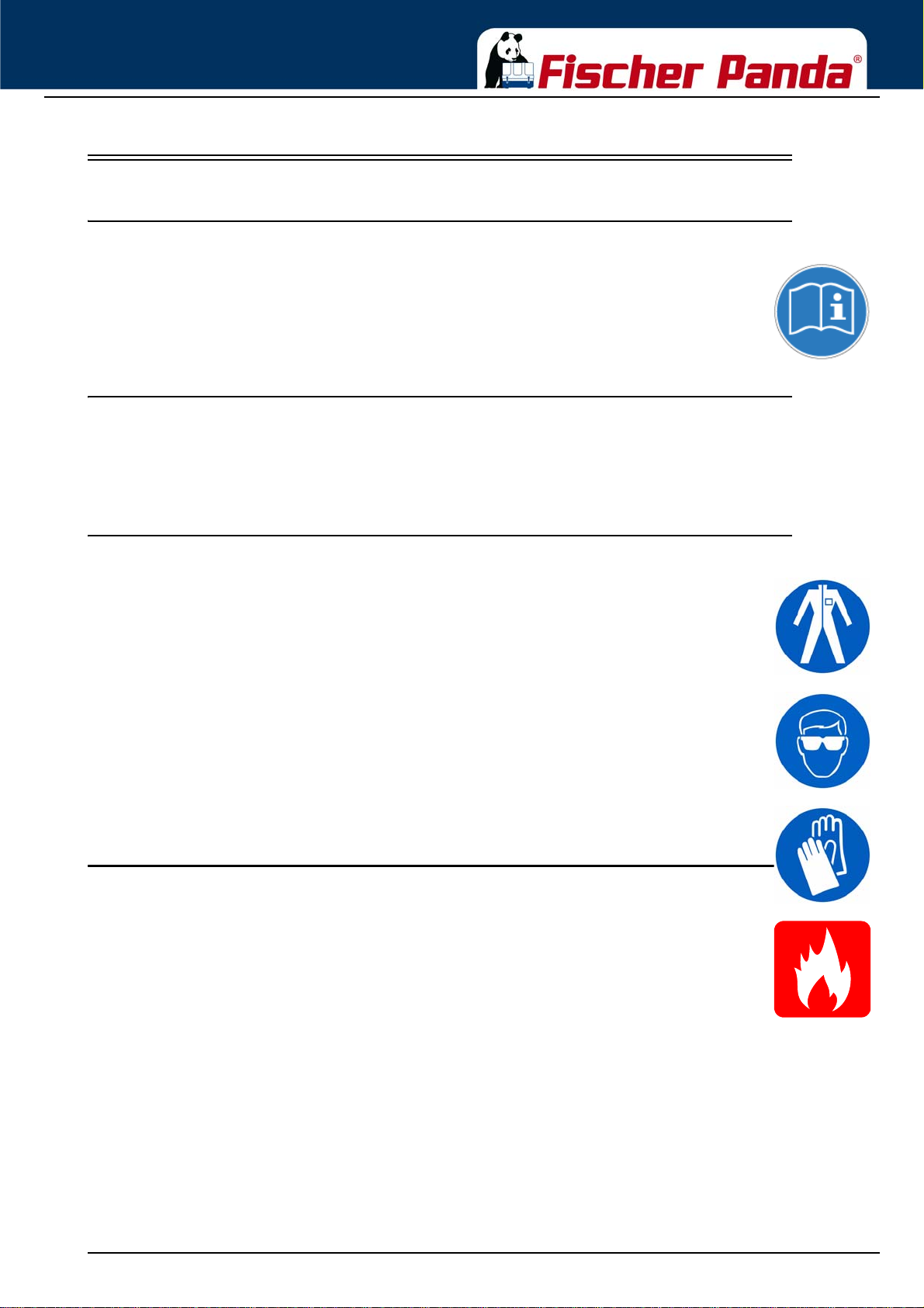
1.5.3 Personal protective clothing (PPE)
For maintenance and repair work on the equipment, do not wear loose, torn, or ill-fitting clothing
that may catch on protruding parts or come into contact with pulleys, cooling disks, or other rotating
parts, which can cause severe injury.
Wear appropriate safety and protective clothing during work.
Do not operate the generator while under the influence of alcohol, medications, or drugs.
Do not wear head phones or ear buds while operating, servicing, or repairing the equipment.
1.5.4 Cleanliness ensures safety
Keep the generator and its environment clean.
Before cleaning the generator, shut down the equipment and secure it against accidental start-up.
Keep the generator free from dirt, grease, and waste. Store flammable liquids in suitable
containers only and ensure adequate distance to the generator. Check the lines regularly for
leakage and eliminate leaks immediately as applicable.
18.12.15 Kapitel/Chapter 1: General Instructions and Regulations - Seite/Page 17
Page 20
General Instructions and Regulations
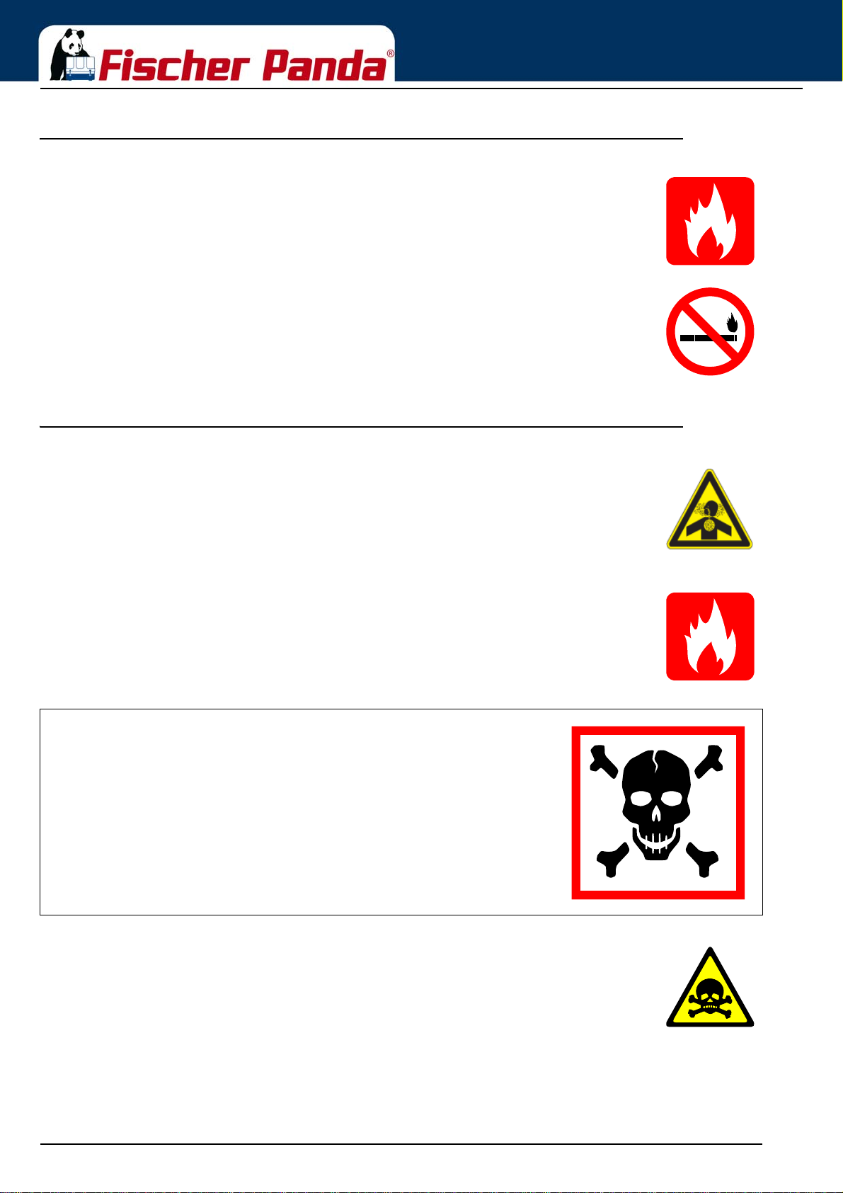
1.5.5 Safe handling of fuels and lubricants
Keep fuels and lubricants away from naked fire.
Before filling up the tank and/or applying lubricant, always shut down the generator and secure it
against accidental start-up.
Do not smoke and avoid naked flame and sparking near fuels and the generator. Fuel is highly
flammable and may explode under certain conditions.
Refuel in well-ventilated open spaces only. If fuel/lubricant was spilled, eliminate fluids
immediately.
Do not mix diesel fuel with petrol or alcohol. Such a mixture can cause fire and will damage the
generator.
Use only approved fuel containers and tank systems. Old bottles and canisters are not adequate.
1.5.6 Exhaust fumes and fire protection
Engine fumes can be hazardous to your health if they accumulate. Ensure that the generator
exhaust fumes are vented appropriately (leak-proof system), and that an adequate fresh air
supply is available for the generator and the operator (forced ventilation).
Check the system regularly for leakage and eliminate leaks as applicable.
Exhaust gases and parts containing such fumes are very hot; they may cause burns under ce rtain
circumstances. Always keep flammable parts away from the generator and the exhaust system.
To prevent fire, ensure that electrical connections are not short-circuited. Check regularly that all
lines and cables are in good condition and that there is no chafing. Bare wires, open chafing
spots, frayed insulation, and loose cable connec tio ns can cause da ngero us electr ic shoc ks, shor tcircuit, and fire.
The generator shall be integrated in the existing fire safety system by the operating company.
CALIFORNIA
Proposition 65 Warning
Diesel engine exhaust and some of its constituents are known to the State of
California to cause cancer, birth defects, and other reproductive harm.
Exhaust gases from diesel motors and some components are carcinogenic and can cause
deformities and other genetic defects.
Seite/Page 18 - Kaptitel/Chapter 1: General Instructions and Regulations 18.12.15
Page 21
General Instructions and Regulations
1.5.7 Safety precautions against burns and battery explosions
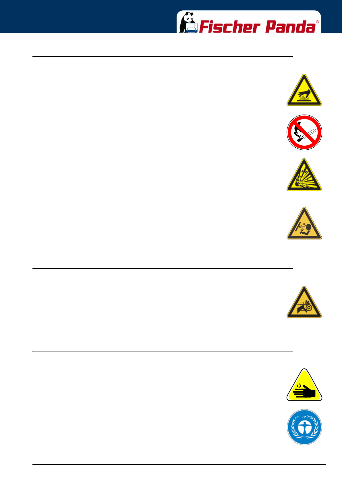
The generator and its cooling agents and lubricants as well as the fuel can get hot while the
generator is operated. Use caution around hot components such as parts containing exhaust
fumes, radiator, hoses, and engine block during operation and after the generator was shut down.
The cooling system may be pressurised. Open the cooling system on ly af ter letting th e engine and
the coolant cool down. Wear appropriate protective clothing (e.g. safety goggles, gloves).
Prior to operation, ensure that the cooling system is sealed and that all hose clamps are tightened .
The battery represents an explosion ha za rd, th is app lies both to th e starter battery and the battery
bank of the AGT generators. While batteries are being charged, a hydrogen-oxygen mixture is
generated, which is highly explosive (electrolytic gas).
Do not use or charge batteries if the fluid level is below the MINIMUM marking. The life span of the
battery is significantly reduced, and the risk of explosion increases. Refill to a fluid level between
maximum and minimum level without delay.
Especially during charging, keep sparks and naked fire away from the batteries. Ensure that the
battery terminals are tightly connected and not corroded to avoid sparking. Use an appropriate
terminal grease.
Check the charge level with an adequate voltmeter or acid siphon. Contact of a metal object
across the terminals will result in short-circuiting, battery damage, and high explosion risk.
Do not charge frozen batteries. Heat the batteries to +16 °C (61 °F) prior to charging.
1.5.8 Protect your hands and body from rotating parts!
Always keep the capsule closed while operating the generator.
To check the V-belt tension, always shut down the generator.
Keep your hands and body away from rotating parts such as V-belt, fans, pulleys, and flywheel.
Contact can cause severe injury.
Do not run the engine without the safety devices in place. Prior to start-up, mount all safety
devices securely and check for proper attachment and function.
1.5.9 Anti-freeze and disposal of fluids
Anti-freeze contains toxic substances. To prevent injury, wear rubber gloves and wash off any antifreeze immediately in case of skin contact. Do not mix different anti-freeze agents. The mixture
may cause a chemical reaction generating harmful substances. Use only anti-freeze that was
approved by Fischer Panda.
Protect the environment. Collect drained fluids (lubricants, anti-freeze, fuel), and dispose of them
properly. Observe the local regulations for the respective country. Ensure that no fluids (not even
very small quantities) can drain into the soil, sewers, or bo die s of wate r.
18.12.15 Kapitel/Chapter 1: General Instructions and Regulations - Seite/Page 19
Page 22
General Instructions and Regulations
1.5.10 Implementation of safety inspections and maintenance
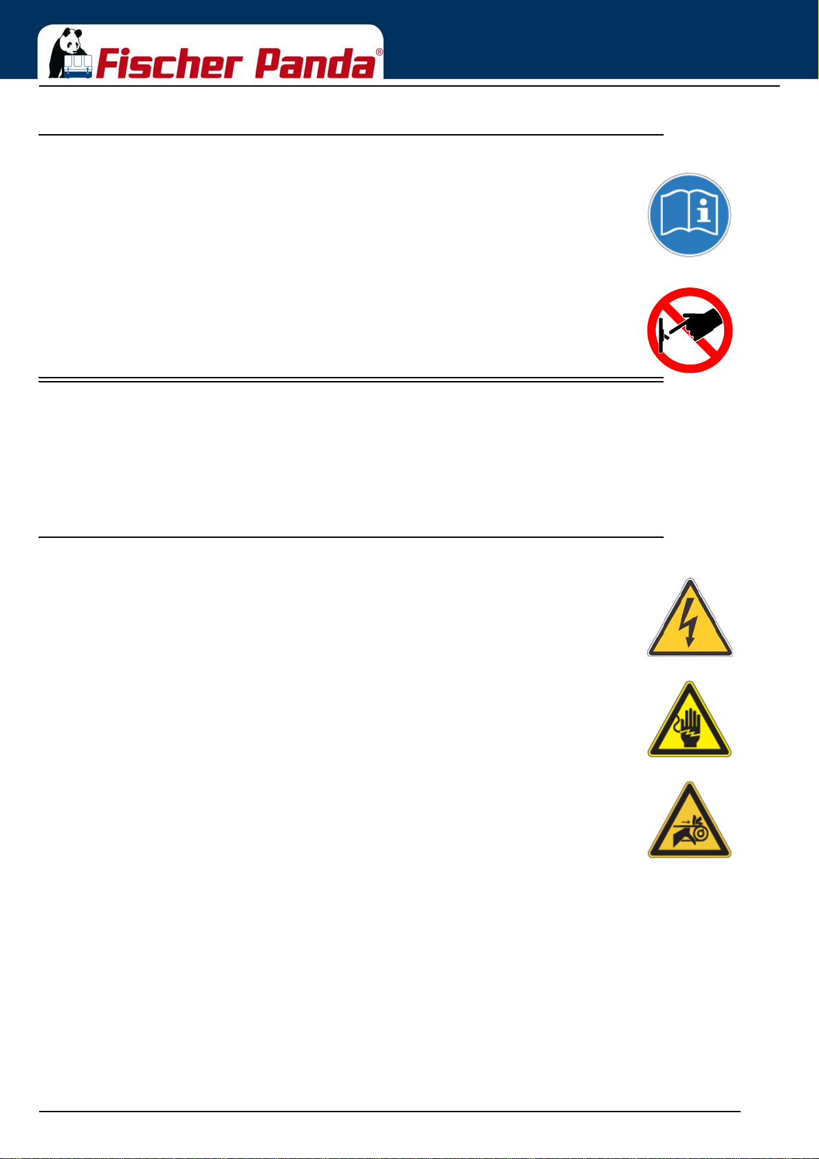
Disconnect the battery from the engine before performing service work. Affix a sign to the control
panel - both the main and the corresponding slave panel - with the instruction “DO NOT START UP
- MAINTENANCE IN PROGRESS“ to prevent unintentio n al start-up.
To prevent sparking due to accidental short-circuiting, always remove the earthing cable (-) first an d
reconnect it last. Do not start work until the generator and all fluids and exhaust system parts have
cooled down.
Use only suitable tooling and appliances and familiarise yourself with their functions to prevent
secondary damage and/or injury.
Always keep a fire extinguisher and a first aid box handy while performing maintenance work.
1.6 Warning and instruction signs
Keep warning and instruction signs clean and legible.
Clean the signs with water and soap and dry them with a soft cloth.
Immediately replace damaged or missing warning and instruction signs. This also applies to the installation of spare
parts.
1.6.1 Special instructions and hazards of generators
The electrical installations may only be carried out by trained and qualified personnel!
The generator must not be operated with the cover removed.
If the generator is being installed without a sound insulation capsule, it must be ensured that all
rotating parts (belt-pulley, belts etc.) are covered and protected so that there is no danger to life
and body!
If a sound insulation covering will be produced at the place of installation, then easily visible signs
must show that the generator must only be switched on while the capsule is closed.
All servicing, maintenance, or repair work may only be carried out when the motor is not running.
Electrical voltages above 48 volts (battery chargers greater than 36 volts) are always dangerous
to life. The rules of the respective regional authority must be adhered to during installation. For
safety reasons, only an electrician may carry out the installatio n of the electrical connectio ns of the
generator.
Seite/Page 20 - Kaptitel/Chapter 1: General Instructions and Regulations 18.12.15
Page 23
General Instructions and Regulations
1.6.1.1 Protective conductor and potential equalisation:
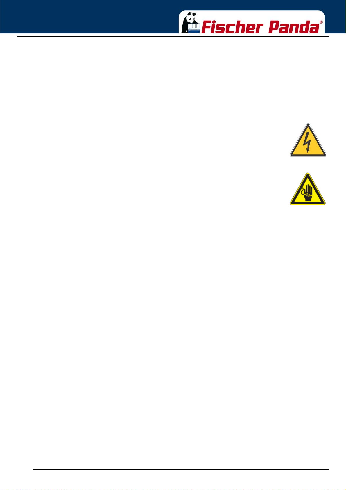
Electric current below 48 V may be life-threatening. Fort this reason systems are grounde d with a prote ctive
conductor. In connection with a RCD the current supply will be disconnected in case of a failure.
Appropriate safety precautions like the RCD and corresponding fuses have to be provided by the customer
to guarantee a save operation of the generator.
1.6.1.2 Protective conductor for Panda AC generators:
The generator is earthed“ as a standard (centre and ground are interconnected in the generator
terminal box by a shunt). This is a basic first-level safety measure, which offers protection as long
as no other measures are installed. Above all, it is designed for delivery and a possible test run.
This „neutralisation“ (Protective Earthing Neutral - PEN) is only effective if all par t s of the electrical
system are jointly „earthed“ to a common potential. The shunt can be removed if this is necessary
for technical reasons and another protective system has been set up instead.
While the generator is being operated, the full voltage is applied to the AC control box, as
well. Therefore, it is essential to ensure that the control box is closed and secured against
touch while the generator is running.
The battery must always be disconnec ted if work on the gener ator or ele ctrical sy stem is to
be carried out, so that the generator cannot be started up unintentionally.
1.6.1.3 Switch off all loads while working on the generator
All loads must be disconnected prior to working on the generator to avoid damage to the devices. In addition, the
semiconductor relays in the AC control box must be disconnected in order to avoid the booster capacitors being
activated during set-up. The negative te rminal of the battery must be disconnected.
Capacitors are required to run the generator. These have two varying functions:
A) The working capacitors
B) The booster capacitors
Both groups are located in a separate AC control box.
Capacitors store electrical energy. High voltages may remain across the capacitor contacts even after they have
been disconnected from the mains. As a safety precaution, do not touch the contacts. If the capacitors must be
replaced or inspected, the contacts shall be short-circuited by connecting an electrical conductor to discharge
potentially remaining potential differences.
If the generator is switched off normally, the working capacitors are automatically discharge d via the winding of t he
generator. The booster capacitors are discharged by means of internal discharge resistors.
For safety reasons, all capacitors must be discharged through short-circuiting before work is carried out on the AC
control box.
1.6.1.4 Potential equalisation for Panda AGT DC generators
For further information specific to your generator, see the chapter installation.
18.12.15 Kapitel/Chapter 1: General Instructions and Regulations - Seite/Page 21
Page 24
General Instructions and Regulations
1.6.1.5 Safety instructions concerning cables
Cable types
It is recommended to use cables that are in compliance with the standard UL 1426 (BC-5W2) with type 3 (ABYC
section E-11).
Cable cross-section
The cable shall be selected taking into account the amperage, cable type, and conductor length (from the positive
power source connection to the electrical device and back to the negative power source conn ection).
Cable installation
It is recommended to install a self-draining cable conduit classified as V-2 or higher in compliance with UL 94 in the
area of the cable guide inside the capsule. It must be ensured that the cable guide is not routed along hot surfaces
such as the exhaust manifold or the engine oil drain screw but instead is installed free from any influence due to
friction and crushing.
1.6.2 Recommended starter battery sizes
Use only batteries approved by the manufacturer as starter batteries.
Use the battery capacity recommended by the engine manufacturer.
ATTENTION!
Prior to installation, verify that the voltage of the starter battery complies with the start-up system
voltage.
e.g. 12 V starter battery for 12 V start-up system
e.g. 24 V starter battery for 24 V start-up system (e. g. 2x 12 V in series)
1.6.3 Important instructions for batteries - starter and/or traction batteries
ATTENTION!!! Start-up:
Installation of battery connection lines.
Observe the instructions installation guidelines of the battery manufacturer.
Observe the regulations “ABYC regulation E11 AC and DC electrical systems on boats“, as EN
ISO 10133:2000 “Small craft -- Electrical systems -- Extra-low-voltage DC installations“, as
applicable!
The battery compartment and the corresponding installation shall be dimensioned
adequately.
The batteries can be separated mechanically or with an adequate power relay.
Seite/Page 22 - Kaptitel/Chapter 1: General Instructions and Regulations 18.12.15
Page 25
General Instructions and Regulations
Observe the applicable instructions concerning fire and explosion protection of the battery
manufacturer.
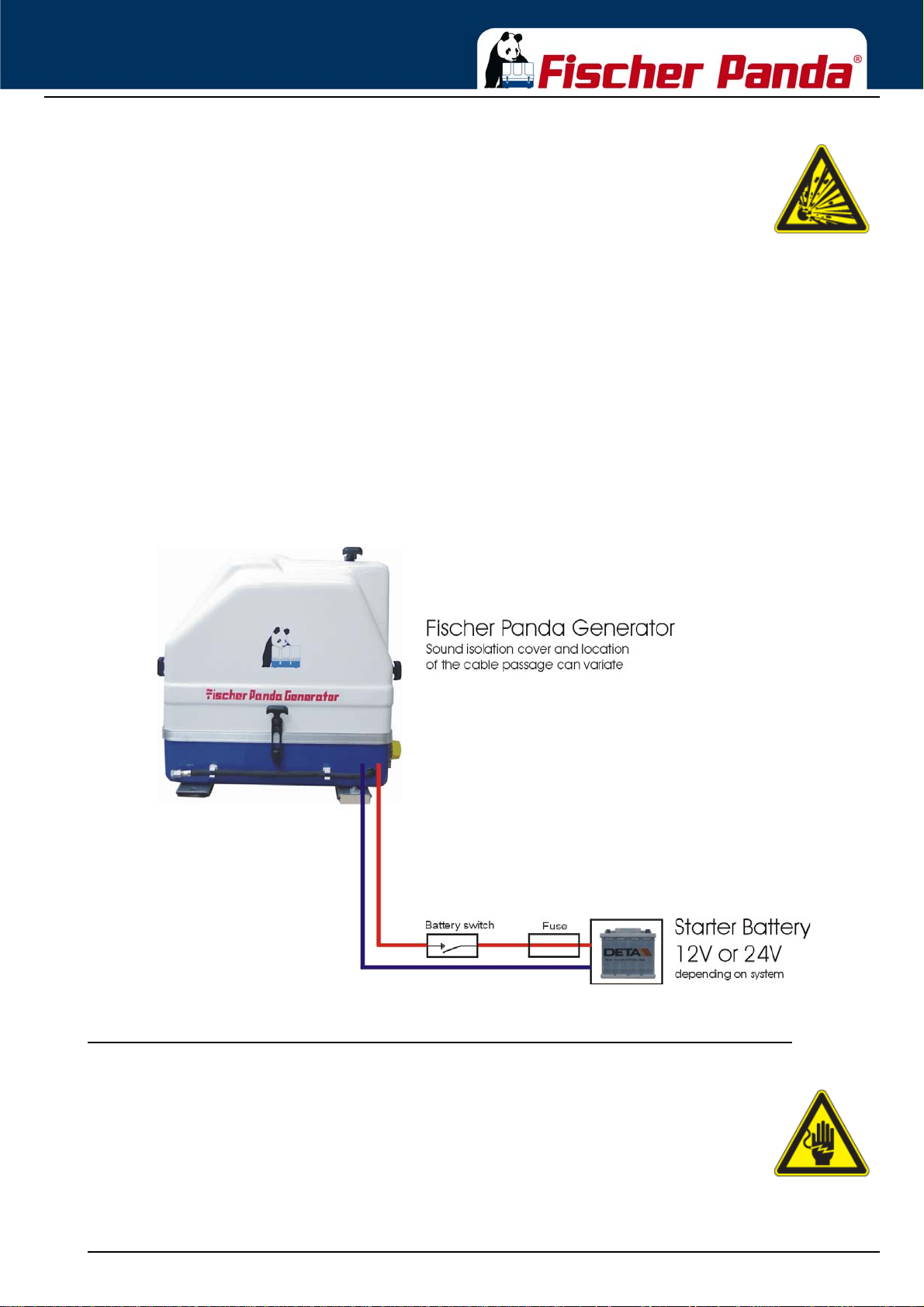
Install a fuse of appropriate size in the positive connection of the starter battery. Install as close to
the battery as possible but with a max. distance of 300 m m (1 2 in) fro m th e ba tte ry.
The cable from the battery to the fuse shall be protected with a conduit/protective sleeve against
fraying.
Use self-extinguishing and fire-protected cables for installation that are designed for max. temperatures of 90 °C,
195 °F.
Install the battery cables in such a way that the insulation cannot be removed by chafing or other mechanical
stresses.
The battery terminals must be protected against accidental short-circuiting.
Inside the Fischer Panda generator capsule, the positive battery cable must be routed so that it is protected from
heat and vibrations by means of an adequate conduit/protective sleeve. It must be installed so that it does not come
into contact with rotating parts or such that heat up during operation such as pulley, exhaust manifold, exhaust pipe,
and motor itself. Do not overtighten the cable, as it may be damaged otherwise.
After completing the installation, perform a test run of the generator and check the battery cable installation during
and after the test run. Implement corrections as necessary.
Fig. 1.6-1: Sample diagram for starter battery installation
1.6.4 General safety instructions for handling batteries
These instructions shall apply in addition to the instructions of the battery manufacturer:
• While you are working on the batteries, a second person should be within earshot to help you if
necessary.
• Keep water and soap ready in case battery acid is burning your skin.
• Wea r ey e pr ot ect i on an d prote ctive clothing. Do not touch your eyes while handlin g ba tte r ies.
18.12.15 Kapitel/Chapter 1: General Instructions and Regulations - Seite/Page 23
Page 26
General Instructions and Regulations
• If you have acid splashes on the skin or clothing, wash them out with lots of water and soap.
• If acid sprays into your eyes, immediately flush them with clean water until no more burning is
felt. Immediately seek medical assistance.
• Do not smoke near the batteries. Avoid naked fire. The area around batteries is a potentially
explosive atmosphere.
• Ensure that no tools are dropped on the battery terminals; cover them as necessary.
• Do not wear jewellery or watches on your arms during installation that might short-circuit the
battery. Otherwise, there is a risk of skin burns.
• Protect all battery contacts against accidental contact.
• For battery banks: Use only deep cycle batteries. Starter batteries are not suitable. Lead-acid gel
batteries are recommended. They are maintenance- free, cycle stable, and do not release gases.
• Never charge a frozen battery.
• Avoid battery short-circuits.
• Ensure proper ventilation of the battery to vent gases that may be released.
• Battery connection terminals must be checked for proper seating before operation.
• Battery connection cables shall be installed with utmost care and shall be checked fo r excessive
heating under load. Check the battery near vibrating components regularly for chafing and
insulation defects.
ATTENTION! For battery charger generators (Fischer Panda AGT-DC)!
Prior to installation, verify that the voltage of the battery bank complies with the output
voltage of the generator.
Seite/Page 24 - Kaptitel/Chapter 1: General Instructions and Regulations 18.12.15
Page 27
In case of Emergency First Aid / Im Notfall -
11
1
2
1
3
1
4
1
5
Erste Hilfe
3. In case of Emergency First Aid / Im Notfall - Erste Hilfe
First Aid in case of accidents by electrical shocks
5 Safety steps to follow if someone is the victim of electrical shock
Do not touch the injured person while the generator is running.
Switch off the generator immediately.
If you cannot switch off the generator, pull, push, or lift the person to safety using a
wooden pole, rope or some nonconducting material.
Call an emergency doctor as soon as possible.
Immediately start necessary first aid procedures.
18.12.15 Kapitel/Chapter 3: In case of Emergency First Aid / Im Notfall - Erste Hilfe - Seite/Page 29
Page 28
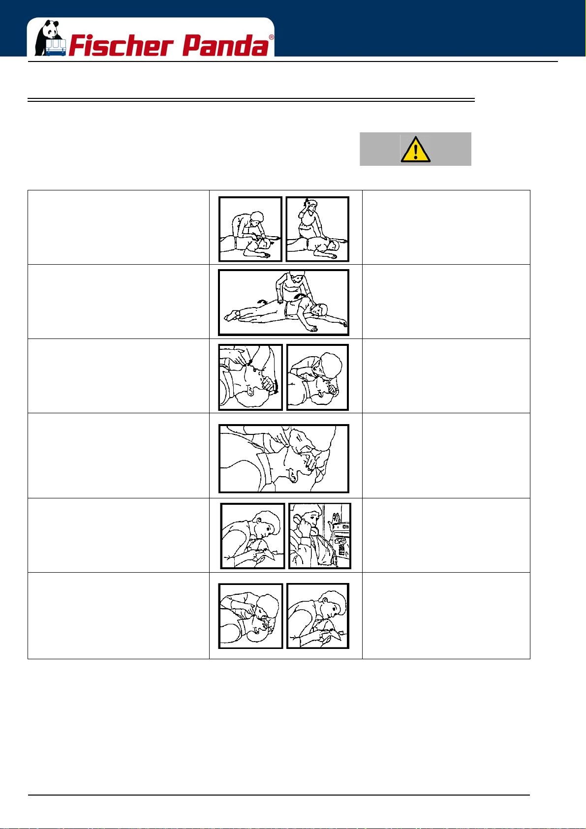
3.1 WHEN AN ADULT STOPS BREATHING
Warning:DO NOT attempt to perform the rescue breathing
techniques provided on this page, unless certified.
Performance of these techniques by uncertified
personnel could result in further injury or death to the
victim.
In case of Emergency First Aid / Im Notfall -
Erste Hilfe
Does the Person Respond?
1
Tap or gently shake victim.
Shout, “Are you OK?“
Roll Person onto Back.
3
Roll victim towards you by pulling slowly.
Open Airway.
4
Tilt head back, and lift chin.
Shout, “Are you OK?“
Give 2 Full Breaths.
6
Keep head tilted back.
Pinch nose shut.
Seal your lips tight around victim's mouth.
Give 2 full breaths for 1 to 1½ seconds each.
Shout, “Help!“
2
Call people who can phone for help.
Check for Breathing.
5
Look, listen, and feel for breathing for 3 to 5
seconds.
Check for Pulse at side of Neck.
7
Feel for pulse for 5 to 10 seconds.
Begin Rescue Breathing.
9
Keep head tilted back.
Lift chin.
Pinch nose shut.
Give 1 full breath every 5 seconds.
Look, listen, and feel for breathing between breaths.
Phone EMS for Help.
8
Send someone to call an ambulance.
Recheck Pulse Every Minute.
10
Keep head tilted back.
Feel for pulse for 5 to 10 seconds.
If victim has pulse, not breathing, continue
rescue breathing. If no pulse, begin CPR.
Seite/Page 30 - Kaptitel/Chapter 3: In case of Emergency First Aid / Im Notfall - Erste Hilfe 18.12.15
Page 29

Basics
3. Basics
3.1 Intended use of the machine
The Fischer Panda generator is made to produce electrical energy out of diesel fuel.
The diesel fuel is converted to mechanical energy by the diesel engine. This mechanical energy drives the
generator. In the genset, the mechanical energy is converted to electrical energy. This process is controlled by
(sometimes external) components, the remote control panel and the VCS (voltage control system).
Sufficient amount of fuel and combustion air is necessary for this process. Arising exhaust and heat must be
conducted according to the specification.
If the electrical power is fed to a local net, the regulations and installation instructions of the system operator and the
regional authorities with reference to the power network/shipboard power supply system must be respected. Safety
applications and safety devices (including lightening conduc tor, personal protection switch, ect.) have to be installed.
Misapplication of the product can damage and destroy the product and the electrical net inclusive all load which is
attached to the net, and contain hazards like short circuit, ect. It is not allowed to modify the product in any case.
Never open the sound cover during operation! The safety and hazard notes of the manual must be respected !
3.2 Purpose of the manual and description of the definitions of the trained persons/operators/users
This manual contains the working instructions and operating guidelines for the owner and user of Fischer Panda
generators.
The manual is the base and the guideline for the correct installation and maintenance of Fischer Panda generators.
It does not substitute the technical evaluation and should be used as an example guide only. The installation must
be undertaken and proved by a suitable qualified/trained person and should be in accordance with the law as
required by the country and special situation. All work has to be undertaken a cco rd ing to the state of the technology.
3.2.1 Trained persons
Qualified persons for the mechanical components are motor mechanics or persons with similar
qualification and training.
Trained persons for the electrical components are electricians or persons with similar qualification and
training.
After the installation the trained person has to instruct the owner about the operation and maintenance of the
generator. This must include the hazards of the generator use.
3.2.2 Operator
The operator is responsible for the operation of the generator.
After the installation, the operator must be instructed concerning the operation and maintenance of the generator.
This has to include the hazards during operation of the generator, different operating conditions, and instructions for
the maintenance.
The operator must read and follow the manual and must respect the hazard notes and safe ty instructions.
18.12.15 Kapitel/Chapter 3: Basics - Seite/Page 29
Page 30
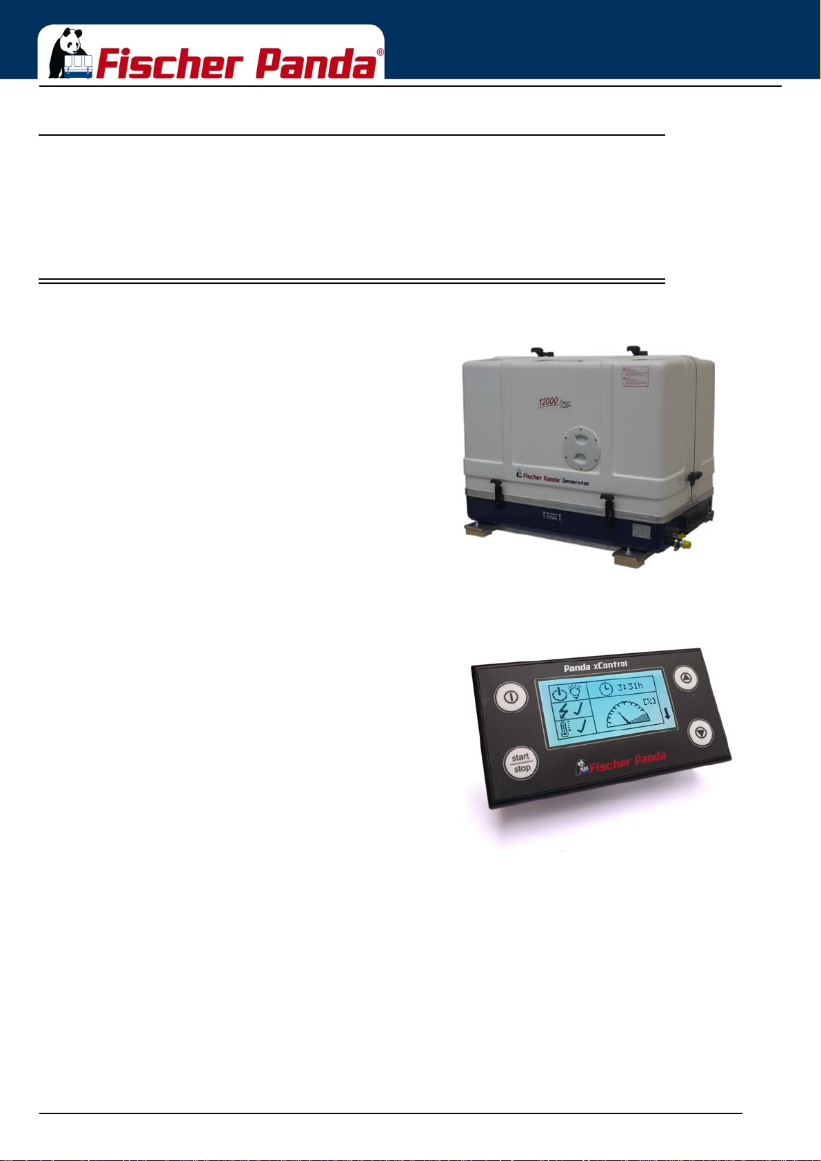
Basics
3.2.3 User
Users are persons, established by the operator, to operate the generator.
The operator has to ensure that the user has read and understood the manual and that all hazard notes and safety
instructions are respected. The user must be instructed by the operator regarding his activity at the generator,
especially concerning the maintenance.
3.3 Components of the xGenerator
Fig. 3.3-1: Panda xGenerator1. Panda xGenerator
r
representative picture
representative picture
Fig. 3.3-2: xControl panel2. Control Panel Panda xControl
Seite/Page 30 - Kaptitel/Chapter 3: Basics 18.12.15
Page 31
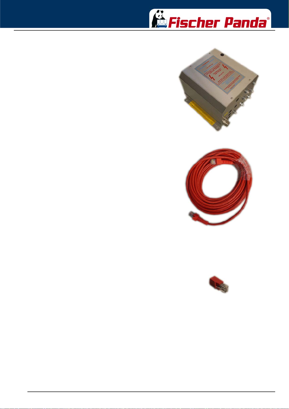
Basics
representative picture
Not present at all models
Fig. 3.3-3: AC-Control box3. AC-Control Box
Fig. 3.3-4: FP- Bus cable 15 mtr4. FP- Bus cable 15 mtr
Fig. 3.3-5: Termination resistor5. Termination resistor
18.12.15 Kapitel/Chapter 3: Basics - Seite/Page 31
Page 32
The Fischer Panda manual comprises the following
components:
a.- Transparent envelope with general information, war-
ranty terms, installation certificates, and service list.
b.- Generator manual
c.- Spare parts catalogue „Installation & Service Guide“
d.- Engine manual from the engine manufacturer
e.- Generator circuit diagram
representative picture
3.4 Range of operation
Basics
Fig. 3.3-6: Manual6. Fischer Panda manual
Reliable power supply on sailing boats.
3.5 Panda transport box
3.5.1 Bolted Fischer Panda transport box
1. Remove the bolts for cover / sidewalls
2. Remove the cover
3. Remove the loose accessories
4. Remove the bolts for sidewalls / floor pallet
5. Remove the sidewalls
6. Open the generator attachment
3.5.2 Fischer Panda transport box with metal t ab closure
1. Bend up the metal tab closures on the transport box lid
2. Remove the cover
3. Remove the loose
4. Bend open the metal tab closures at the bottom of the transport box
5. Remove the sidewalls
6. Open the generator attachment
Seite/Page 32 - Kaptitel/Chapter 3: Basics 18.12.15
Page 33
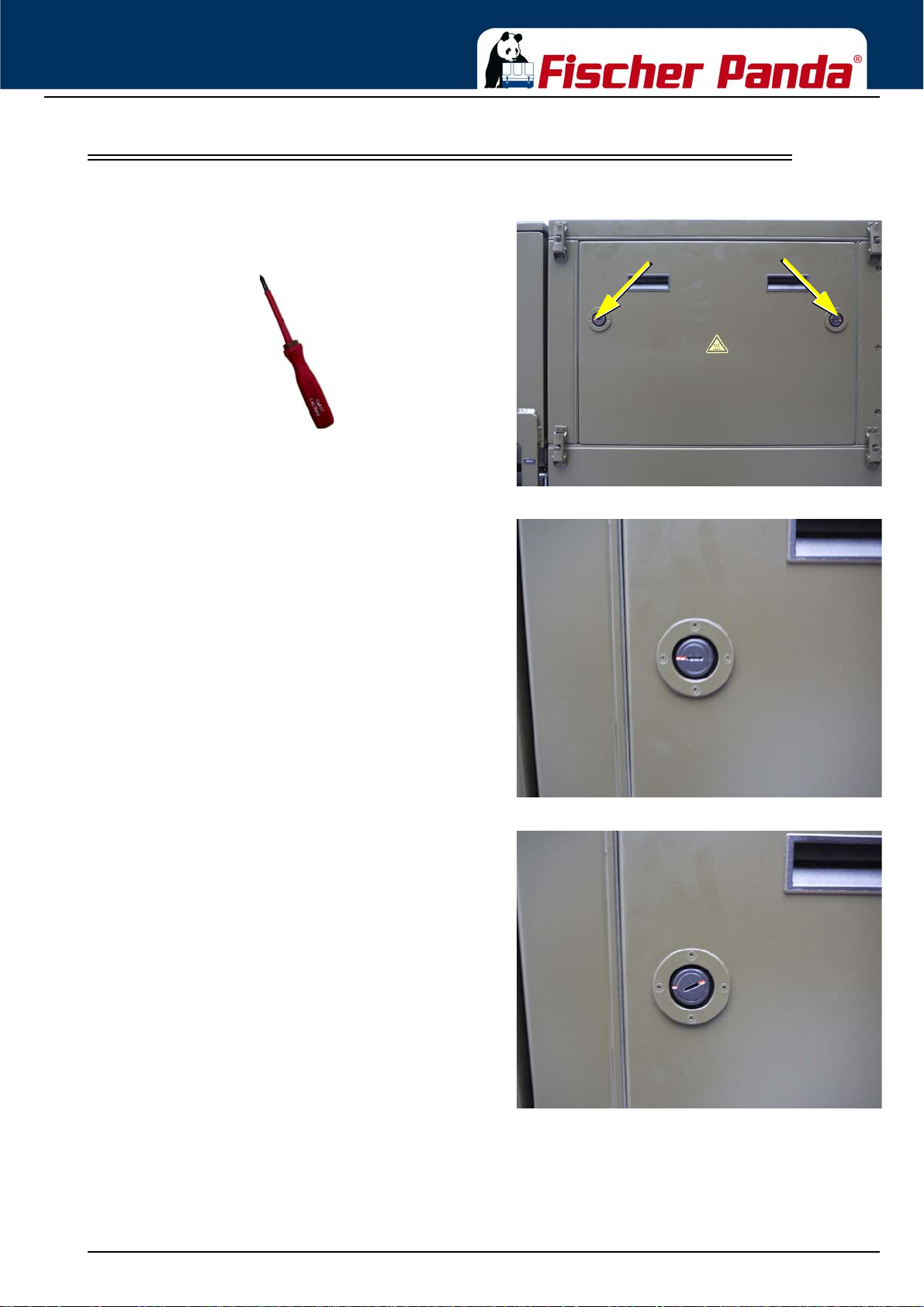
Basics
3.6 Opening the MPL sound insulation capsule
be rotated roughly 180° counter-clockwise. Use a flat
head screwdriver. Pull the sidewalls out by gripping into
the slots.
Fig. 3.6-1: Sound insulation capsule, side partT o open the soun d insulation cap sule, the closures must
Fig. 3.6-2: Closure lockedClosure locked
Fig. 3.6-3: Closure openClosure open
18.12.15 Kapitel/Chapter 3: Basics - Seite/Page 33
Page 34
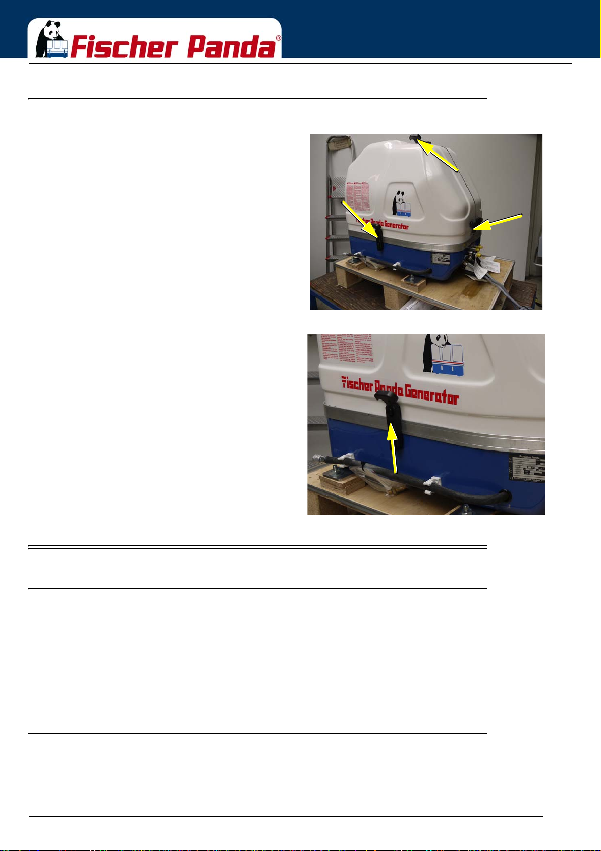
3.6.1 Opening the GFK sound insulation capsule
Basics
Fig. 3.6-1: Lash closuresGFK sound insulation capsule with lash closures
direction and lift the lash of the closure pin. After lifting
off the lashes, the sound isolation cover upper part can
be removed.
3.7 Transport and loading/unloading
3.7.1 Transporting the generator
• The generator must always be upright for transport.
Fig. 3.6-2: Lash closuresTo open the lash closures pull the handle in arrow
• For transport, the Fischer Panda transport box shall be used for the generator. The generator shall be securely
attached to the bottom of the box.
• For loading/unloading, an adequate industrial truck shall be used.
• Depending on the transpor t distance ( e.g. air carg o), the ge nerator fluids ( coolant, engine o il, fuel) may have to be
drained. The corresponding instructions and warnings must be fitted to the transport packaging.
3.7.2 Loading/unloading of the generator
For loading/unloading the generator, appropriate ring eye bolts shall be installed in the holes in the support rails. The
load bearing capacity of each ring eye bolt must at least equal the generator weight.
Seite/Page 34 - Kaptitel/Chapter 3: Basics 18.12.15
Page 35

Basics
Fig. 3.7.2-1: Lifting yoke (example)An adequate lifting yoke shall be used for transport/
loading.
3.8 Special service instructions and measures for extended machine downtimes and decommissioning
Note: The decommissioning and storage must be undertaken and
proved regarding the operation and storage situation.
Fischer Panda takes no responsibilty for damages
through wrong decommissioning and storage.
Downtimes are categorised in the following groups:
• Short downtime (1 to 3 months)
• Medium term downtime / hibernation (3 to 6 months)
• Extended downtime / decommissioning (more than 6 months)
3.8.1 Instructions for the starter battery for extended downtimes
Note: Information starter batteryStarter batteries
Self-discharge of batteries is a physical and chemica l
process and cannot be avoided even if the battery is
disconnected
• For extended downtimes, the battery shall be disconnected from the genset.
• Charge battery regularly. Observe instructions of the battery manufacturer.
Depending on the battery type, check the acid level before charging and refill each cell up to the marking using
distilled water as necessary.
Modern starter batteries are typically maintenanc e- fr ee .
Deep discharge will damage the battery and can render it unusable.
Keep battery clean and dry. Clean battery poles (+ and -) and terminals regularly and coat with acid-free and acidresistant grease. During assembly, ensure good contact of the terminal connections.
General limits for lead-acid batteries:
2.1 V / cell corresponds with full battery (charged).
1.95 V / cell corresponds with empty battery - recharge.
For a 12 V battery, the following applies:
18.12.15 Kapitel/Chapter 3: Basics - Seite/Page 35
Page 36

Basics
- 11.7 V lower open-circuit voltage (battery empty), recharge battery.
- 12.6 V upper open-circuit voltage (full battery) - trickle charge full battery at 13.2 V.
For a 24 V battery, the following applies:
- 23.4 V lower open-circuit voltage (battery empty), recharge battery.
- 25.2 V upper open-circuit voltage (full battery) - trickle charge full battery at 26.4 V.
These values are based on a battery temperature of 20-25°C. Observe the instructions from the battery
manufacturer.
Note: Starter battery recommendationFischer Panda recommends:
• Install battery circuit breaker and switch to OFF on the
machine. (Cutting the battery circuit.)
• Secure the battery plus terminal close to the battery.
• Regularly check contacts for corrosion.
3.8.2 Measures for short downtimes
Short downtime (1 to 3 months)
• Measure battery charge status based on open-circuit voltage.
• During downtimes >7 days, disconnect battery (e.g. battery main switch to position 0).
• Check the battery within 2 months and allow the engine to warm up for min. 10 min.
• Fill fuel tank to 100% (level to full).
3.8.3 Measures for medium term downtimes / hibernation
Medium term downtimes (3 to 6 months)
3.8.3.1 Courses for preservation:
• Check battery charge status and recharge regularly, roughly every 2 months, as necessary. Observe instructions
of the battery manufacturer.
• Check cooling water anti-freeze level and refill as necessary.
The anti-freeze agent must not be older than 2 years. The anti-freeze conte nt shall be between 40 % and 60 % to
ensure corrosion protection of the cooling water circuit. Top off coolant if necessary.
If the cooling water is drained, e.g. after engine surface protection is applied, no water may remain inside the
engine during the downtime. The control unit must be marked accordingly with a note specifying “NO COOLING
WATER“.
• Drain engine oil as specified. Refill engine with preservative oil to the max. level on the oil dipstick.
• Drain diesel from tank and refill with a protective mixture (90 % diesel and 10 % preservative oil) (level to full).
Crank engine without start.
• Dismount V-belt as specified, wrap and store in a dry location. Protect against UV radiation.
Attention! Cover alternator apertures.
Cleaning fluids and preservatives must not enter the
alternator. Risk of destroying the alternator.
• Clean engine as per manufacturer's instructions.
Seite/Page 36 - Kaptitel/Chapter 3: Basics 18.12.15
Page 37

Basics
• Spray engine parts and V-belt disks with preservative.
• Clean air filter housing and spray with preservative (metal housing only).
• Close off intake and exhaust apertures (e.g. with tape or end caps).
Attention! Before recommissioning, remove preservatives and
protective measures.
3.8.3.2 Measures for removing surface protection after medium term downtimes (3 to 6 months).
• Check battery charge status and recharge if necessary. Observe instructions of the battery manufacturer.
• Check cooling water anti-freeze level and cooling water level and refill as necessary.
• Drain engine oil. Replace oil filter and engine oil as per the specification.
• Remove preservatives from the engine with petroleum spirit.
• Degrease V-belt disks and mount V-belt according to instructions. Check V-belt tension!
• If applicable, open turbocharger oil pressure line and fill clean engine oil into channel.
• Hold engine stop lever in zero delivery position and crank engine manually several times.
• Clean air filter housing with petroleum spirit, check air filter and replace if necessary.
• Remove covers from exhaust aperture and intake apertures.
• Connect battery. Close battery main switch.
• Hold stop lever on generator motor in neutral position and crank starter for ap prox. 10 seconds. Then, pause for 10
seconds. Repeat this procedure 2 times.
• Perform visual check of the generator similar to initial commissioning and start up generator.
3.8.4 Measures for extended downtimes / decommissioning
Downtimes (more than 6 months)
3.8.4.1 Courses for preservation:
• Check battery charge status and recharge regularly, roughly every 3 months, as necessary. Observe instructions
of the battery manufacturer.
• Check cooling water anti-freeze level and refill as necessary.
The anti-freeze agent must not be older than 2 years. The anti-free ze content shall be betwe en 40 % and 60 % to
ensure corrosion protection of the cooling wa ter ci rcu it. Top off coolant if necessary.
If the cooling water is drained, e.g. after engine surface pr otection is applied, no water may remain inside the
engine during the downtime. The control unit must be marked accordingly with a note specifying “NO COOLING
WATER“.
• Drain engine oil as specified. Refill engine with preservative oil to the max. level on the oil dipstick.
• Drain diesel from tank and refill with a protective mixture (90 % diesel and 10 % preservative oil) (level to full).
Crank engine without start.
• Dismount V-belt as specified, wrap and store in a dry location. Protect against UV radiation.
• Disconnect battery. Coat terminals with acid-free grease.
18.12.15 Kapitel/Chapter 3: Basics - Seite/Page 37
Page 38
Basics
Attention! Cover alternator apertures.
Cleaning fluids and preservatives must not enter the
alternator. Risk of destroying the alternator.
• Clean engine as per manufacturer's instructions.
• Spray engine parts and V-belt disks with preservative.
• Clean air filter housing and spray with preservative (metal housing only).
• Spray preservative on intake and exhaust side of exhaust turbocharger (where applicab le) and reconnect the lines.
• Remove valve cover and spray inside of valve cover, valve stems, springs, rocker, etc. with preservative oil.
• Remove injection nozzle and coat cylinder surface with preservative oil. Hold stop lever in zero delivery position
and crank engine manually several times. Refit injection nozzles with new seals (at an operation hour of min. 100
hours after the last change). Observe torque values.
• Spray radiator cover and tank cover or radiator cover on expansion tank lightly with preservative oil and refit.
• Close off intake and exhaust apertures (e.g. with tape or end caps).
Note: For storage for more than 12 months, the preservation
measures shall be checked annually and supplemented
as necessary.
Attention! Before recommissioning, remove preservatives and
protective measures.
3.8.4.2 Measures for removing surface protection after extended downtimes /
recommissioning (over 6 months):
• Check battery charge status and recharge if necessary. Observe instructions of the battery manufacturer.
• Check cooling water anti-freeze level and cooling water level and refill as necessary.
• Drain engine oil. Replace oil filter and oil as per the specification.
• Remove preservatives from the engine with petroleum spirit.
• Degrease V-belt disks and mount V-belt according to instructions. Check V-belt tension!
• If applicable, open turbocharger oil pressure line and fill clean engine oil into channel.
• Hold engine stop lever in zero delivery position and crank engine manually several times.
• Clean air filter housing with petroleum spirit, check air filter and replace if necessary.
• Remove covers from exhaust aperture and intake apertures.
• Connect battery. Close battery main switch.
• Hold stop lever on generator motor in neutra l position and crank starter for approx. 10 seconds. Then, pause for 10
seconds. Repeat this procedure 2 times.
• Perform visual check of the generator similar to initial commissioning and start up generator.
Note: Fischer Panda recommends:
After extended downtimes, a full 150 h inspection as per the
inspection list should be performed.
Seite/Page 38 - Kaptitel/Chapter 3: Basics 18.12.15
Page 39
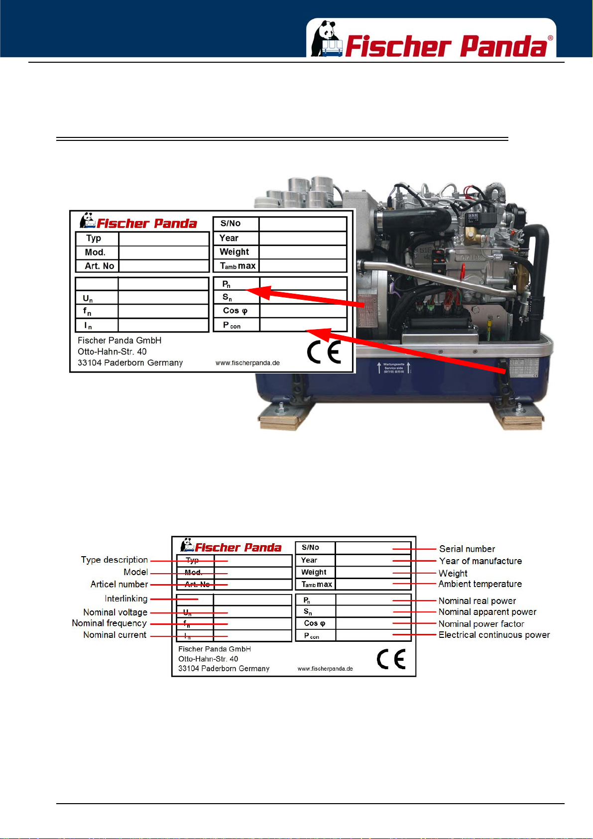
The Panda Generator
4. The Panda Generator
4.1 Type plate at the Generator
Fig. 4.1-1: Type plate at the generator
Fig. 4.1-2: Description type plate
18.12.15 Kapitel/Chapter 4: The Panda Generator - Seite/Page 39
Page 40
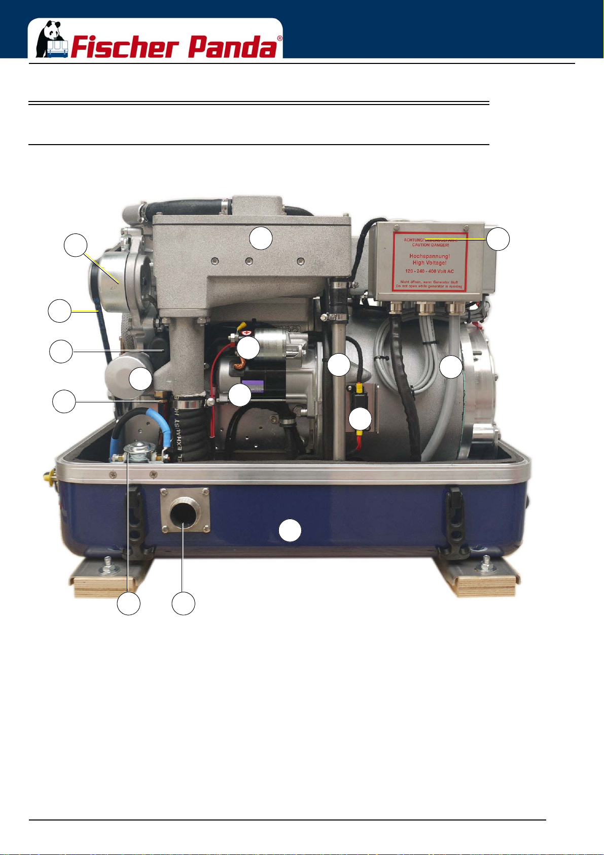
4.2 Description of the Generator
05
03
04
12
14
07
06
09
13
01
02
15
1110
08
01. Water-cooled exhaust manifold / Heat exchanger (inside)
02. DC-alternator
03. V-belt for DC-alternator and cooling water pump
04. Oil pressure switch
05. Magnetic switch for starter motor
06. Starter Motor
07. Engine oil filter
08) Thermo sensor at exhaust
09. Flat fuse
10. Ground isolation relay (option)
11. Exhaust connection
12. Sound-cover base part
13. Cooling water return line
14. Generator housing with winding
15. Generator power terminal box
4.2.1 Right Side View
Fig. 4.2.1-1: Right Side View
The Panda Generator
Seite/Page 40 - Kaptitel/Chapter 4: The Panda Generator 18.12.15
Page 41
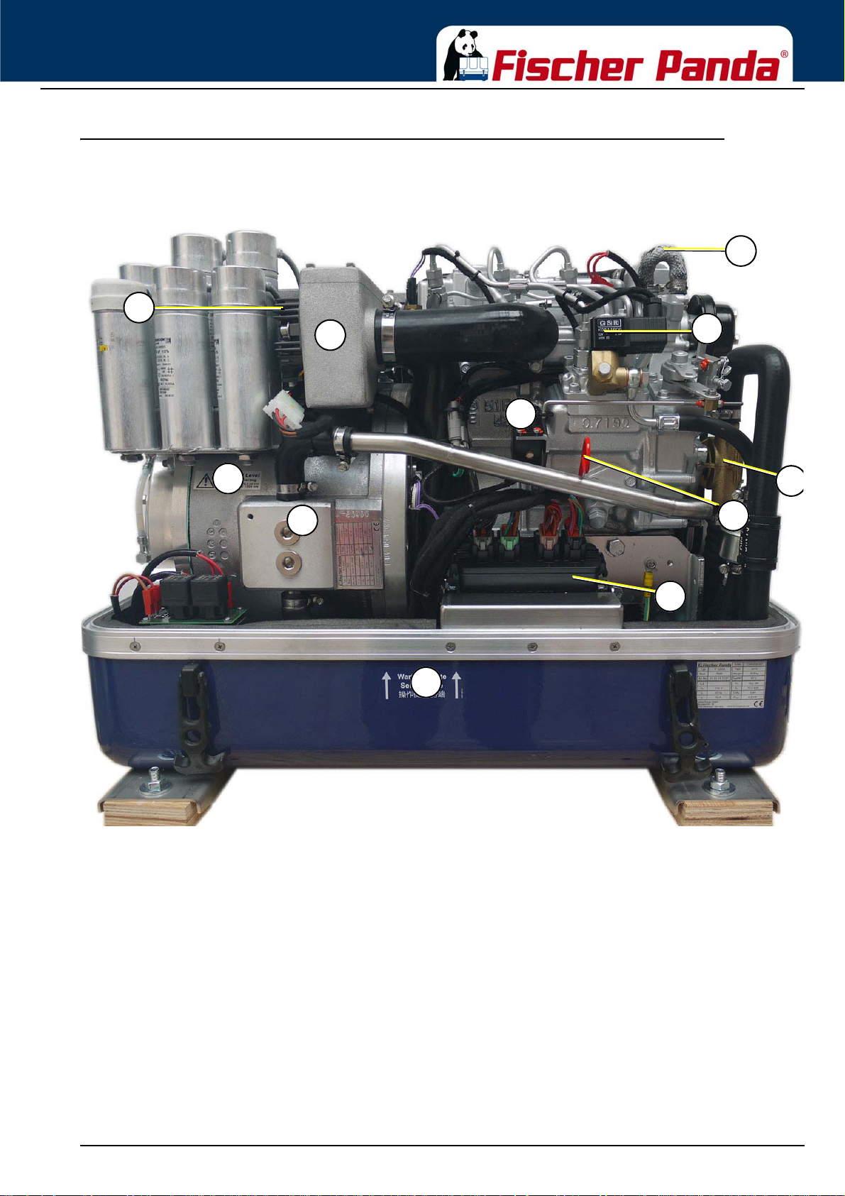
The Panda Generator
02
04
05
03
01
06
07
08
11
10
09
01) Charge control for DC-alternator
02) Air suction housing with air filter
03) Actuator for speed control
04) Generator housing with winding
05) Cooling water connection block
06) Sound cover base part
07) xControl ECU
08) Oil dipstick
09) Seawater pump
10) Fuel solenoid valve
11) Internal cooling water pump
12) Ventilation screw thermostat housing
4.2.2 Left Side View
Fig. 4.2.2-1: Left Side View
18.12.15 Kapitel/Chapter 4: The Panda Generator - Seite/Page 41
Page 42
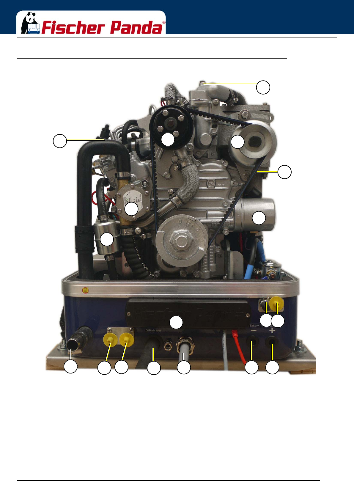
4.2.3 Font View
03
07
04
06
08
09
10
11
12
13
14
05
01
02
15 18
16
17
01) Ventilation screw thermostat housing
02) Fuel solenoid valve
03) Internal cooling water pump
04) Alternator DC
05) V-belt for DC-alternator and internal cooling water pump
06) Engine oil filter
07) Seawater pump
08) Fuel fine filter
09) Seawater inlet
10) Fuel intake connection (feed line)
11) Fuel backflow connection (return line)
12) xControl connection panel
13) Oil drain hose
14) Power out
15) Passage for battery cable - (negative pole)
16) Intake external cooling water expansion tank
17) Back flow external cooling water expansion tank
18) Passage for battery cable + (positive pole)
The Panda Generator
Fig. 4.2.3-1: Front View
Seite/Page 42 - Kaptitel/Chapter 4: The Panda Generator 18.12.15
Page 43
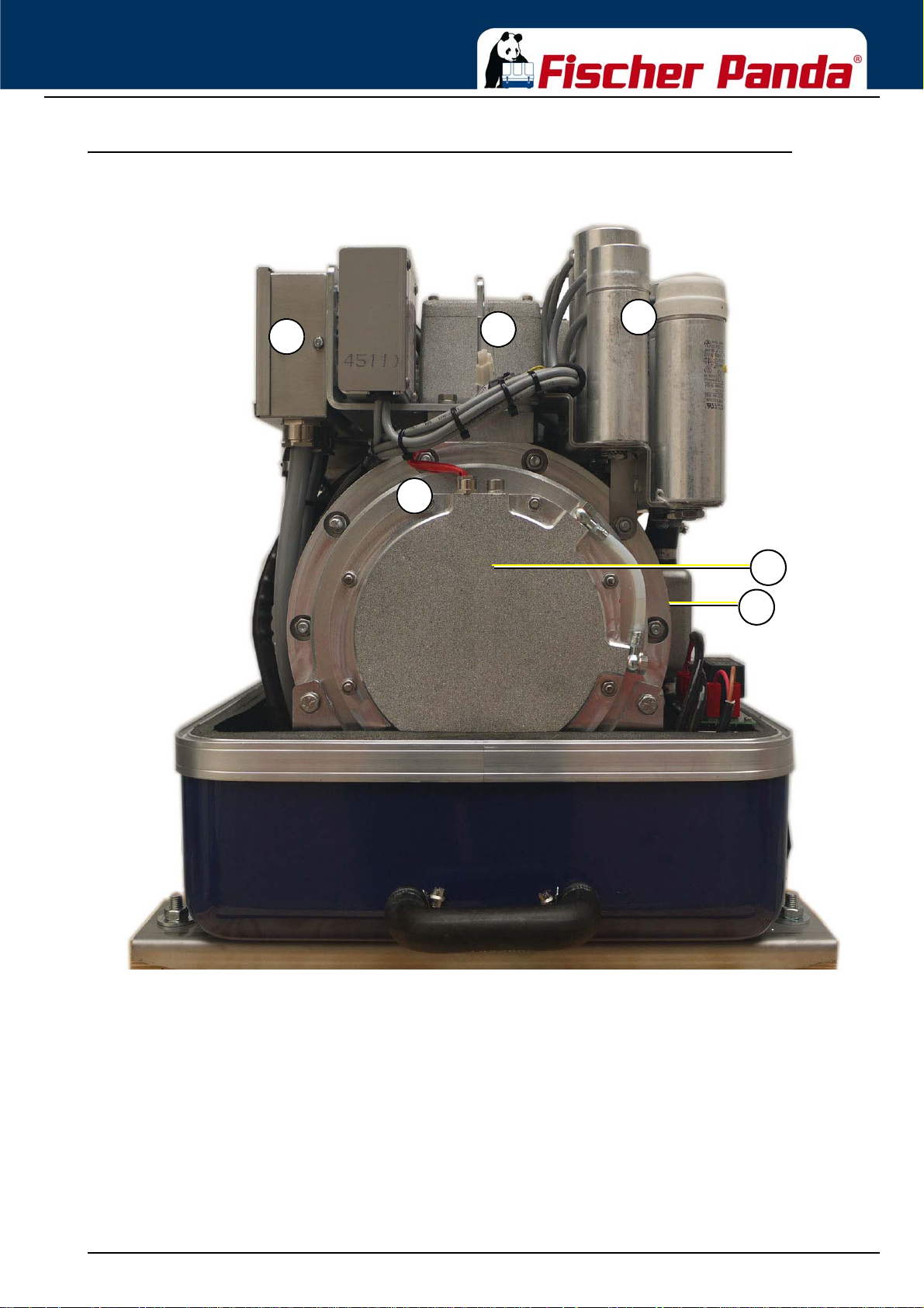
The Panda Generator
01
04
02
03
06
05
01. Generator terminal box
02) Air suction housing with air filter
03) Capacitor
04) Generator front plate
05) Oil cooled bearing
06) Cooling water connection block
4.2.4 Back View
Fig. 4.2.4-1: Back View
18.12.15 Kapitel/Chapter 4: The Panda Generator - Seite/Page 43
Page 44
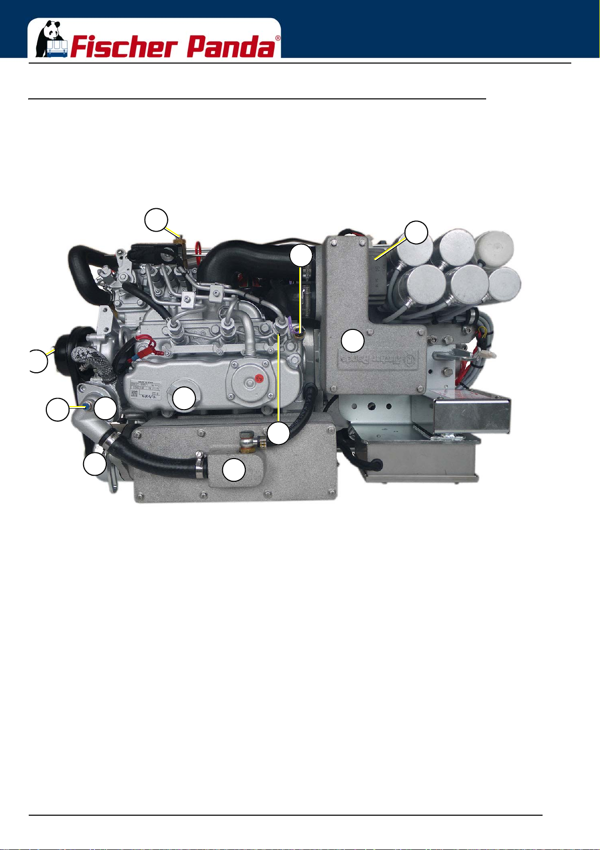
4.2.5 View from above
06
10
07
01
02
03
04
05
08
09
11
01) Ventilation screw fuel solenoid valve
02) Ventilation screw internal cooling water pump
03) Ventilation screw thermostat housing
04) Thermostat housing with thermostat set
05) DC-alternator/Dynamo
06) Oil filler neck
07) Water cooled exhaust manifold / Heat exchange (inside)
08) Injection nozzle
09) Cylinder head thermosensor
10) Air suction housing with air filter
11) Charge control for DC-Alternator
The Panda Generator
Fig. 4.2.5-1: View from above
Seite/Page 44 - Kaptitel/Chapter 4: The Panda Generator 18.12.15
Page 45
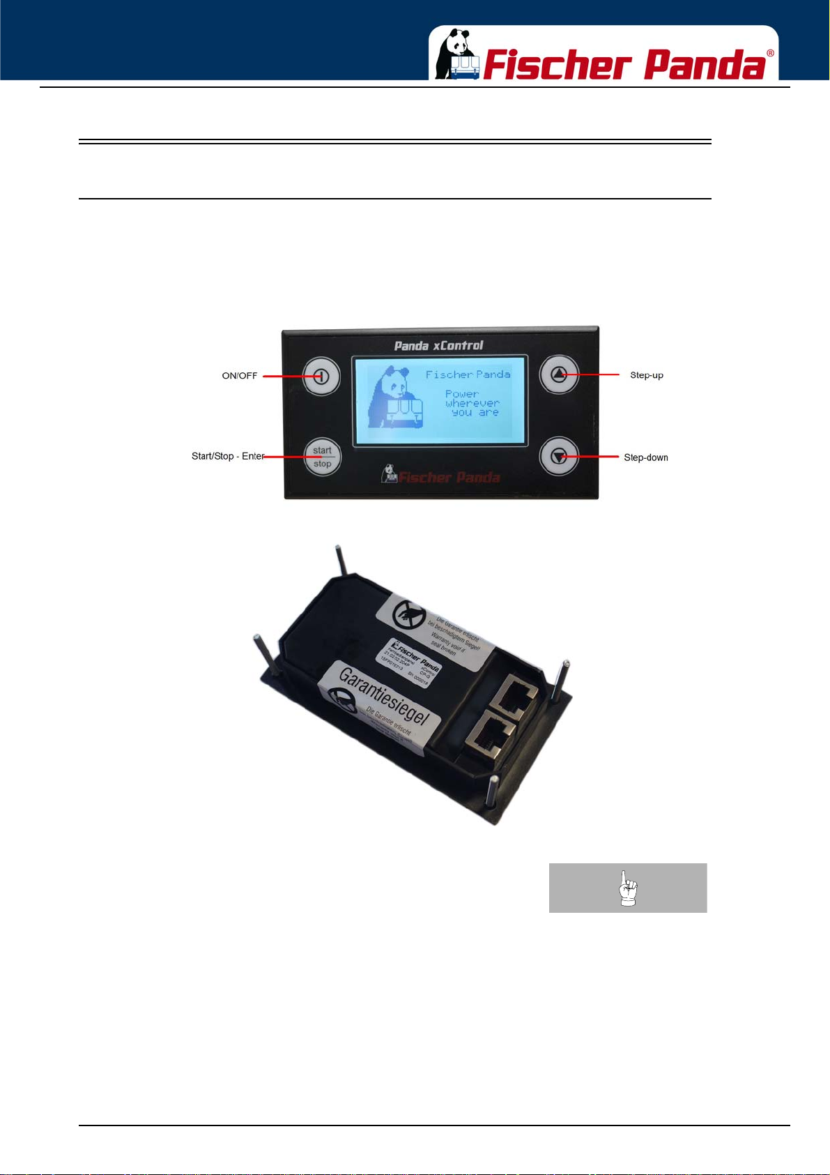
The Panda Generator
4.3 Details of functional units
4.3.1 xControl panel
The control panel is fitted with various monitoring functions, which increase functional reliability and operating safety
of the generator . Various parts of the generator are monitore d with sensors which, when trig gered , gene rate an er ror
message and can shut down generator operation under certain circumstances to prevent damage.
Fig. 4.3-1: xControl CP-G Front Side
Fig. 4.3.1-2: xControl CP-G Reverse Sidel
Notice!:See xControl manual for details!
18.12.15 Kapitel/Chapter 4: The Panda Generator - Seite/Page 45
Page 46
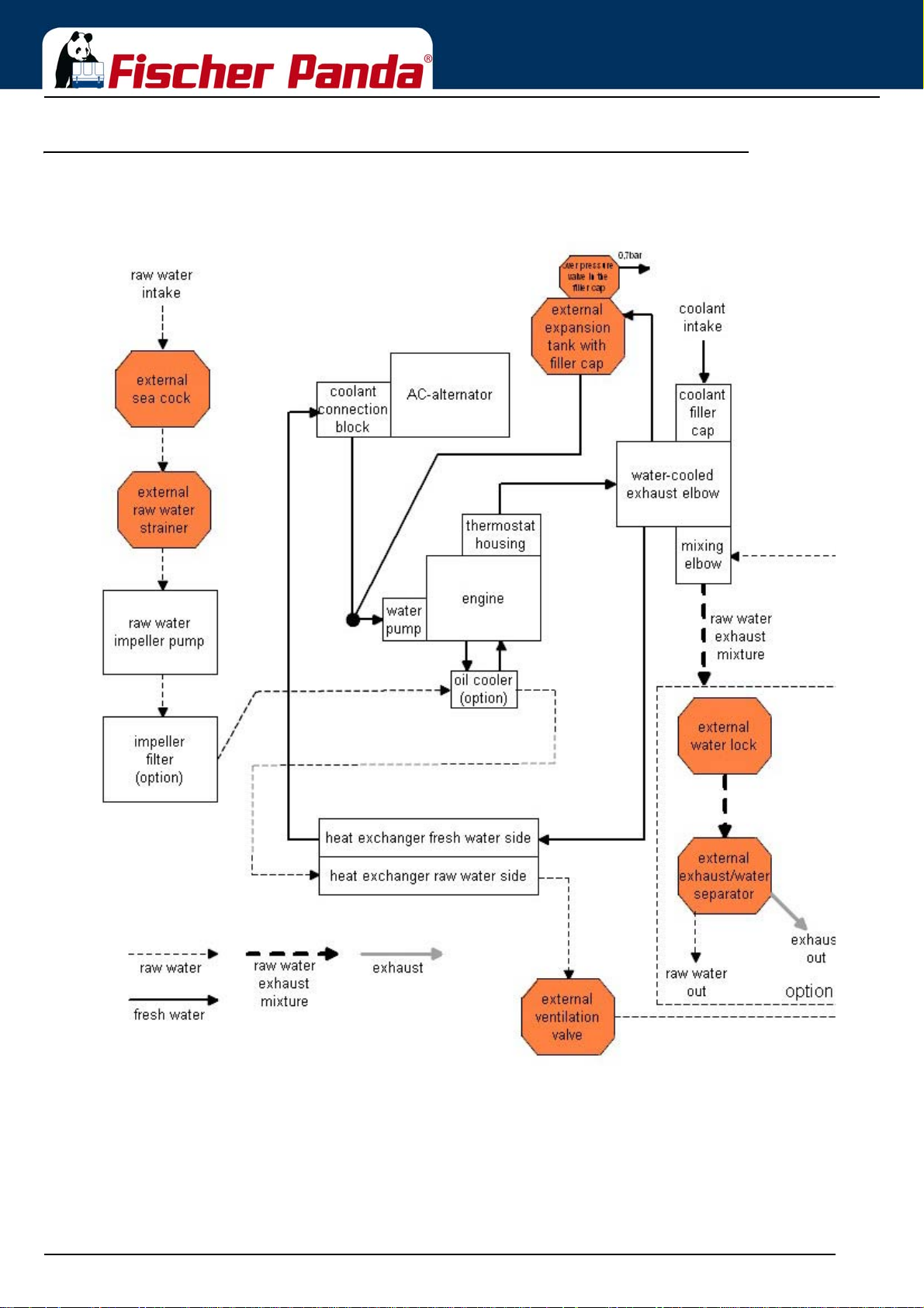
4.3.2 The Cooling System - Schema
Fig. 4.3.2-1: The Cooling System - Schema
The Panda Generator
Seite/Page 46 - Kaptitel/Chapter 4: The Panda Generator 18.12.15
Page 47
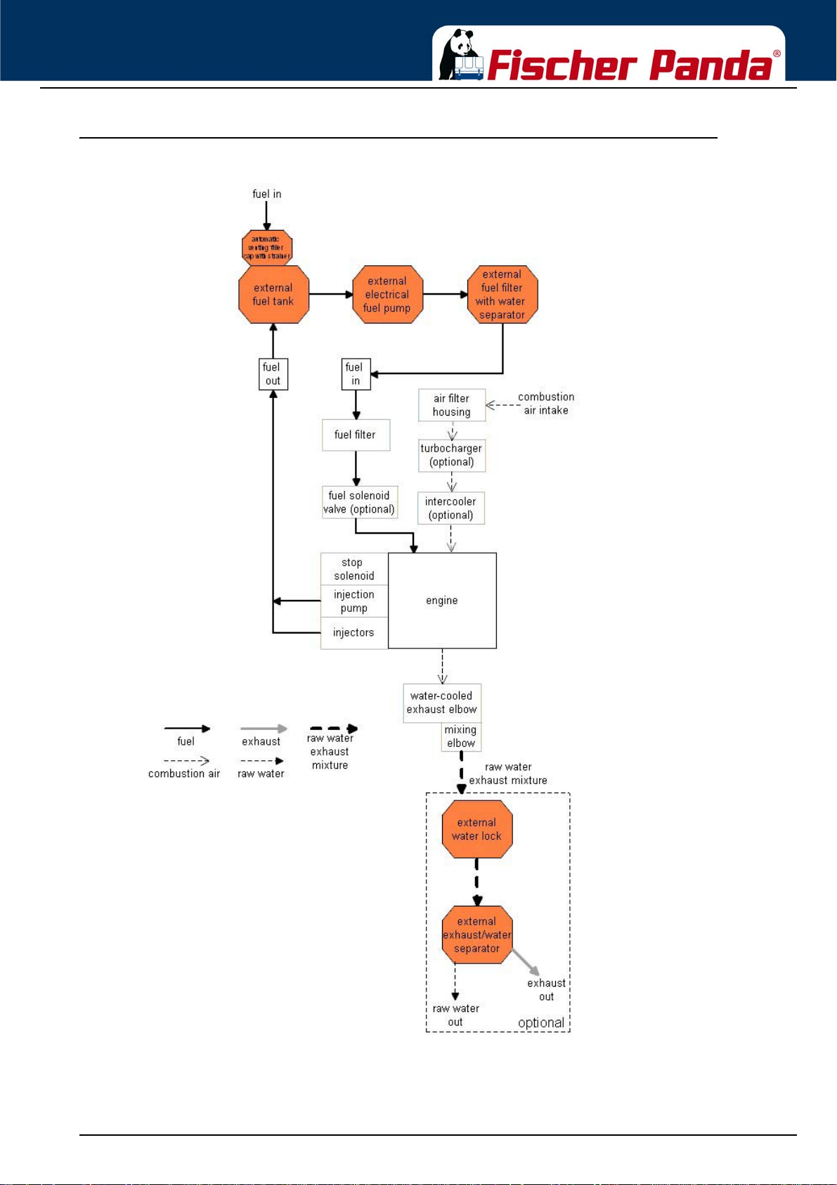
The Panda Generator
4.3.3 The Fuel System - Schema
Fig. 4.3.3-1: The Fuel System - Schema
18.12.15 Kapitel/Chapter 4: The Panda Generator - Seite/Page 47
Page 48
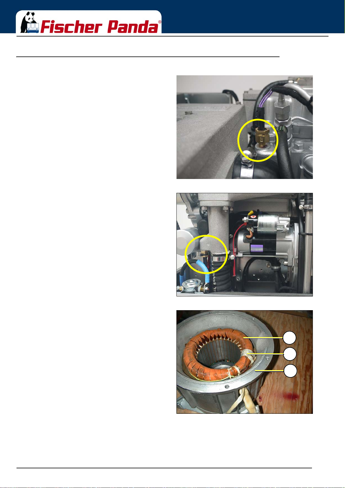
4.3.4 The operation surveillance system
1
3
2
The thermo-sensor at the cylinder head serves to monitor the
generator temperature.
The Panda Generator
Fig. 4.3.4-1: Thermo-seneor at cylinder headThermo-sensor at cylinder head
If the impeller pump stops and delivers no more raw water,
the exhaust connection becomes extremely hot.
1. Generator winding
2. Thermo-sensor
3. Housing
Fig. 4.3.4-2: Thermo-sensor at exhaust connectionThermo-sensor at exhaust connection
Fig. 4.3.4-3: Thermo-sensor in the generator windingThermo-sensor in the generator winding
A thermo-sensor inside the windings to protect the generator
winding, is installed.
Seite/Page 48 - Kaptitel/Chapter 4: The Panda Generator 18.12.15
Page 49
The Panda Generator
bearing only)
The generator bearing is equipped with an oil thermo-switch,
which switches the engine off, if the oil temperatu re becomes
too high.
At generators with xControl the thermo switch is for service
only
Fig. 4.3.4-4: Oil thermo-switchThermo-switch at the front plate (Models with oil cooled
Fig. 4.3.4-5: Oil pressure switchOil pressure switch
In order to be able to monitor the lubricating oil system, an oil
pressure switch is built into the system. The oil pressure
switch is at the rear of the engine (In front of the electrical
starter).
18.12.15 Kapitel/Chapter 4: The Panda Generator - Seite/Page 49
Page 50
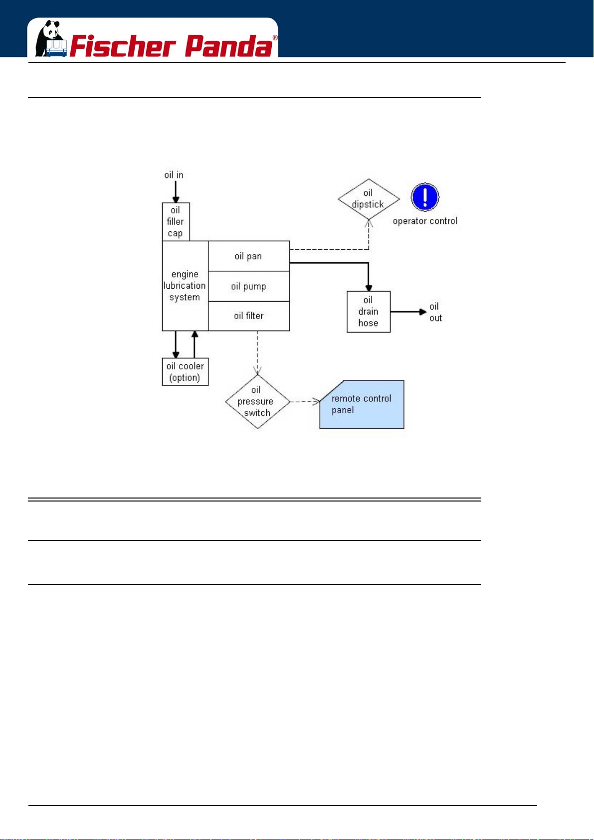
4.3.5 The Oil Circuit - Schema
The Panda Generator
Fig. 4.3.5-1: The Oil Circuit - Schema
4.4 Remote Control Panel - see separate Control Panel Manual
4.4.1 Starting the Generator - see separate Control Panel Manual
4.4.2 Stopping the Generator - see separate Control Panel Manual
Seite/Page 50 - Kaptitel/Chapter 4: The Panda Generator 18.12.15
Page 51
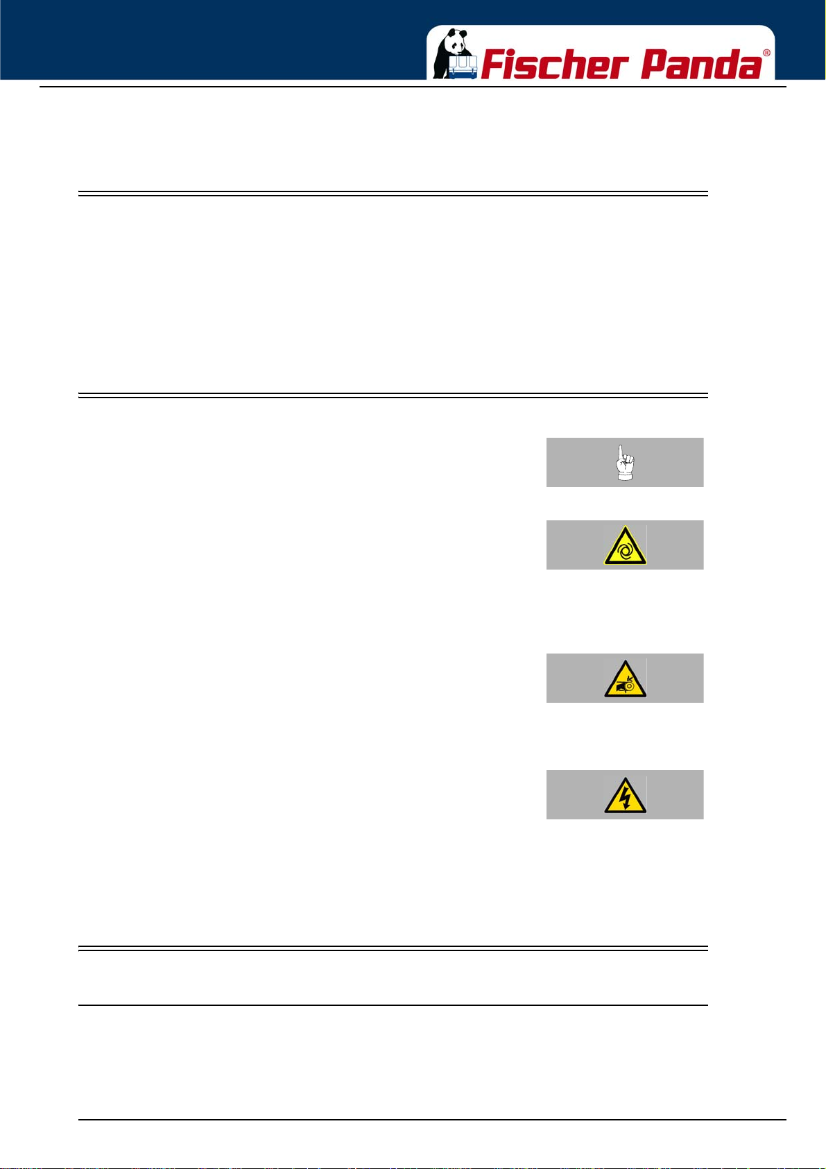
Generator operation instruction
5. Generator operation instruction
5.1 Personal requirements
Only instructed persons are allowed to run the generator. Instructed Persons has read the manual of the generator
and all ancillary components and external equipment. He must be acquaint with the specific risks and safety instructions.
Only persons who are expected to perform their tasks reliably are permitted as personnel. Persons whose reaction
capability is impaired, e.g. through drugs, alcohol or medication are not permitted.
When selecting the personnel, the stipulations regarding age and occupation applying at the loca tion must be observed.
5.2 Hazard notes for the operation
Notice!:Please note the safety first instructions in front of this
manual.
automatic start device. This means the generator can be
started by an external signal.
To avoid an unexpected starting of the generator, the starter
battery must be disconnected before start working at the
generator.
Do not run the generator with removed sound cove r. If it is
necessary to test the generator without sound cover, pay
special attention. Never do this work alone. Do all service,
maintenance and repair with engine stopped.
installation and maintenance can result in severe
personal injury and/or material damage.
Electrical voltages above 48 volts (battery chargers greater
than 36 volts) are always dangerous to life). The rules of the
respective regional authority must be adhered to. Only an
electrician may carry out installation of the electrical
connections for safety reasons.
Warning!: Automatic startDanger for life! - The generator can be equipped with a
Attention!: Danger to lifeRotating parts inside of the generator
Attention!: Danger to Life - High voltageDanger for Life. Improper handling, operation,
5.3 General operating instruction
5.3.1 Operation at low temperatures
The Generator can be started at temperatures down to - 20 °C, therefor the operation fluids like fuel, cooling water,
lubricant oil ect. must be suitable for this t emperatur es. These should be checked before start. Cold start spray ect.
are not allowed to use, or the warranty will be lost.
18.12.15 Kapitel/Chapter 5: Generator operation instruction - Seite/Page 51
Page 52

Generator operation instruction
5.3.1.1 Pre-heating the diesel motor
Pre.champer diesel engines are equipped with a quick gl ow plug. The maximu m pre glow time sho uld not exceed 20
sec. At 20 °C or more the pre glow time should be about 5-6 sec. Below 20 °C the pre glow time should be
increased,
Note:If the operation fluids have been drained and then filled
with cold weather fluids, always run the generator for 10
minutes to ensure the new fuel is present throug hout the
system.
5.3.1.2 Tips regarding starter battery
Fischer Panda recommends normal starter battery use. If an genset is required for extreme winter conditions, then
the starter battery capacity should b e doubled. It is recommended that the starter battery be regularly charged by a
suitable battery-charging device (i.e., at least every 2 Months). A correctly charged starter battery is necessary fo r
low temperatures.
5.3.2 Light load operation and engine idle
If an engine is operated on a load less than 25-30 % of its rated output, the soot of the generator will be observed
which may give cause for concern. The usual results of this operation are heavier than normal lubricating oil
consumption, and oil leaks from the air and exhaust manifolds. This condition is particularly evident on standby
generator set applications.
5.3.2.1 The soot of the generator is due to the fact that:
The cylinder temperatures are too low to ensure complete burning of all the fuel delivered.
A further result is that of abnormal carbon build -up on the valves, piston crowns and exhaust ports. Fuel dilution of
the lubricating oil will also occur.
5.3.2.2 To prevent the soot of the generator following steps should be observed:
Running on light load should be avoided or reduced to the minimum period.
In a period of 50 operation hours the engine or generator set should be run on full load for four hours, to burn off
accumulations of carbon in the engine and exhaust system. This may require the use of a 'dummy load'. The load
should be built up gradually from 30 % to 100 % within 3 hours and hold at 100 % fo r on e hour.
5.3.3 Generator load for a longer period and overload
Ensure the generator is not overloaded. Overloading occurs when the electrical load is higher than the generator
can provide. If this occur for a longer period, the engine may be damaged. Overloading may cause rough running,
high oil and fuel consumption, increased emissions.
For a long engine life, the long therm load should not exceed 80 % of the nominal load. Long therm load is the load
over several hours. It is harmless for the generator to deliver full nominal power for 2-3 hours.
The hole conception of the Fischer Panda generator make sure, that the full power operation at extreme condition
will not increase the engine temperatures over. Please note that the emissions of the generator also increase at full
power operation.
Seite/Page 52 - Kaptitel/Chapter 5: Generator operation instruction 18.12.15
Page 53

Generator operation instruction
5.3.4 Protection conductor:
The standard Panda generator is grounded. The 3-phase connection (delta) centre point is bridged to earth in the
AC output terminal box (mounted on the generator). This is the initial earth safety point and is sufficient to ensure
safe operation however only as long as no other system is inst alled. This syste m is adapted to enab le test running of
the generator before delivery.
The bridge to ground (PEN) is only effective when all components in the electrical system share a common ground.
The bridge to ground can be removed and reconnected to another ground system if required for other safety standards.
Full voltage connections are mounted in the electrical cabinet. It must be ensured that the electrical cabinet is secured and closed while the generator is running.
The starter battery cable should be disconnected when work is being done on either the generator or the electrical
system in order to prevent accidental starting of the generator.
5.3.5 Operating control system on the Fischer Panda generator
Fischer Panda generators are equipped with various sensors/temperatures switches. The combustion engine is
further equipped with a oil pressure control switch, which switches the motor of f, if the oil p ressure sinks to a p ar ticular level.
5.4 Instructions for capacitors - not present at all models
CAUTION! Danger to Life - High voltage
Do not touch the capacitor contact terminals!
The generator's electrical system requires two different groups of capacitors:
A) The booster capacitors
B) The operating capacitors
Both types are mounted in the electrical cabinet. (At some models direct on the generator)
Capacitors store an electrical charge. It is p ossible that even af ter they have been disconnecte d stored energy is still
held. Therefore it is essential that the connectors are not touched.
Should it be necessary to check or test the capacitors, they should be shorted out by using an insulated screw driver .
The operating capacitors are automatically discharged when the generator is stopped in the normal way. The boo-
ster capacitors will be discharged through internal resistors.
For safety however, the capacitors have to be discharged (short circuited) prior to carrying out any work on the AC-
Control box.
5.5 Checks before start - see remote control panel data sheet
Note:The instructions and regulations of the remote control
panel data sheet must be respected.
Respect the safety instruction in front of this manual.
18.12.15 Kapitel/Chapter 5: Generator operation instruction - Seite/Page 53
Page 54

Generator operation instruction
5.6 Starting the generator - see remote control panel data sheet
Note:The instructions and regulations of the remote control
panel data sheet must be respected.
Respect the safety instruction in front of this manual.
5.7 Stopping the generator - see remote control panel data sheet
Note:The instructions and regulations of the remote control
panel data sheet must be respected.
Respect the safety instruction in front of this manual.
Seite/Page 54 - Kaptitel/Chapter 5: Generator operation instruction 18.12.15
Page 55
Installation Instructions
6. Installation Instructions
All connections (hoses, wires etc) and installation instructions are designed and suited for “standard” installation
situations.
In situations where Fischer Panda has no detailed information concerning certain installation requirements (such as
vehicle specifications, maximum vehicle speed -and all other conditions concerning special operating situations) the
installation instructions should be used as an example guide only.
The installation must be undertaken and proved by a suitable qualified/trained person and may in accordance with
the law as required by the country and special situation.
Damages caused by faulty or incorrect installation are not covered by the warranty.
6.1 Personal requirements
The described installation must be done by a technical trained person or a Fischer Panda service point.
6.1.1 Hazard notes for the installation
Follow the general safety instruction at the front of this
manual.
Working at a running generator can result in severe personal
injury. Therefore before starting work at the generator:
Make sure that the generator is stopped and the starter
battery is decanted to guarantee that the genera tor cannot be
inadvertently started.
Do not run the generator with removed sound isol at ion cover
Improper installation can result in severe personal injuries or
material damage.
- Always undertake installation work when the gener ator is
switched off.
- Ensure there is sufficient installation clearance before start
working.
Notice!:see “Safety first!” on Page 12.
Warning!: Risk of injury
Warning!: Risk of injury
- Ensure tidiness and cleanliness at the workplace. Loose
components and tools lying around or on top of each other
are sources of accidents.
- Only perform installation work using commercially available
tools and special tools. incorrect or damaged tools can result
injuries.
Oil and fuel vapours can ignite on contact with ignition
sources. Therefore:
- No open flames during work on the generator.
- Do not smoke.
18.12.15 Kapitel/Chapter 6: Installation Instructions - Seite/Page 55
-Warning!: Danger of fire
Page 56
- Remove oil and fuel residues from the generator and floor.
Installation Instructions
Contact with engine oil, antifreeze and fuel can result in
damage to health
. Therefor:
- Avoid skin contact with engine oil, fuel and antifreeze.
- Remove oil and fuel splashes and antifreeze from the skin
immediately.
- Do not inhale oil and fuel vapours.
installation and maintenance can result in severe
personal injury and/or material damage.
Electrical voltages above 48 volts (battery chargers greater
than 36 volts) are always dangerous to life). The rules of the
respective regional authority must be adhered to. Only an
electrician may carry out installation of the electrical
connections for safety reasons.
operation. Risk of severe burns.
Danger!: Danger of poisoning
ATTENTION!: Danger to Life - High voltageDanger for Life. Improper handling, operation,
Warning!: Hot surface/materialGenerator, oil and antifreeze can be hot during/after
During Installation/maintenance personal protective equipment
is required to minimize the health hazards.
- Protective clothing
- safety boots
- protective gloves
- Ear defender
- safety glasses
Disconnect all load during the work at the generator to avoid
damages at the load.
6.2 Place of installation
6.2.1 Preliminary remark
Instruction!: protective equipment necessary.
Attention!: disconnect all load
• There must be sufficient fresh air supply for the combustion air.
• It has to be ensu re d th at the co oling air sup ply from underneath or sidewise is sufficient.
• During operation the sea cock has to be opened.
• The generator may only be opened by a technical trained person.
• The generator may only be operated by a trained person.
Seite/Page 56 - Kaptitel/Chapter 6: Installation Instructions 18.12.15
Page 57
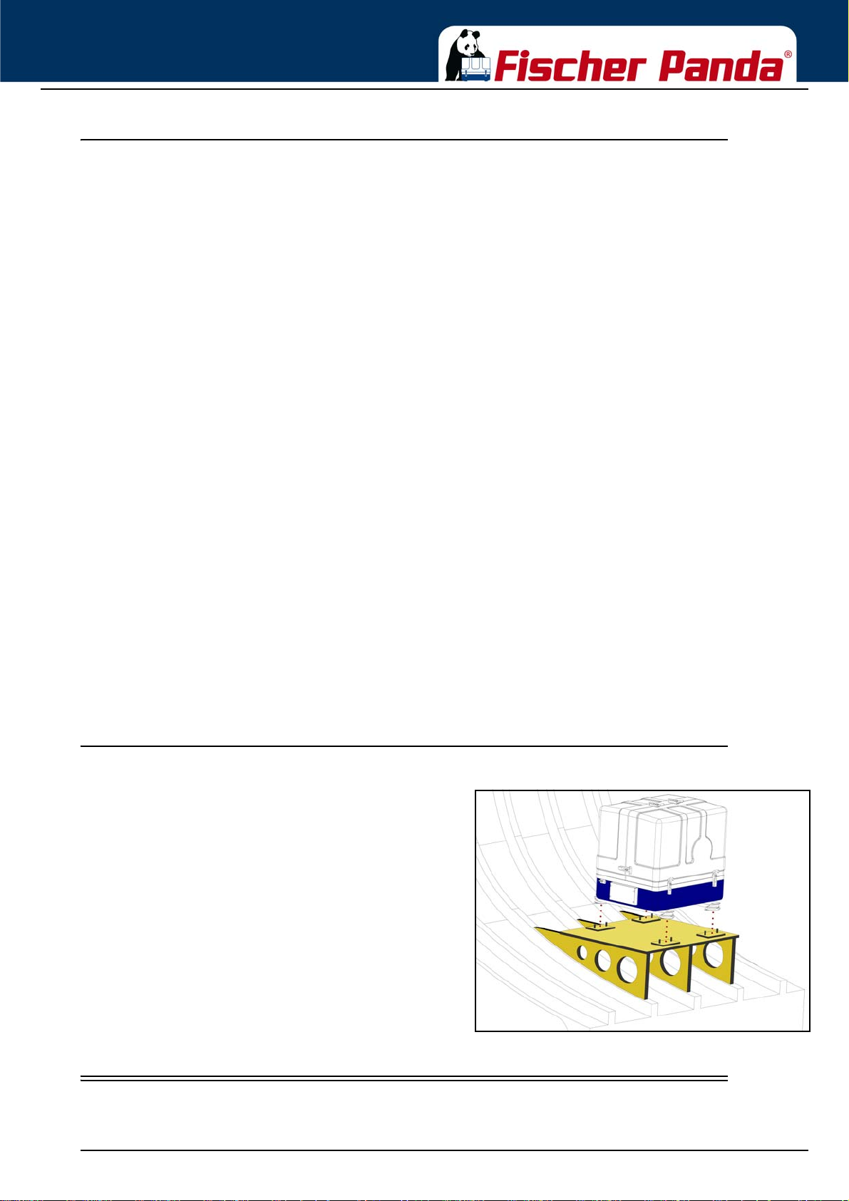
Installation Instructions
6.2.2 Preparing the base - placement
Since Panda generators have extremely compact dimensions, they can be installed in tight locations. Attempts are
sometimes made to install them in almost inaccessible places. Please consider that even almost maintenance-free
machinery must still remain accessible at least at the front (drive belt, water pump) and the service-side (actuator,
dipstick). Please also note that in spite of the automatic oil-pressure sensor it is still essential that the oil level has to
be checked regularly.
The generator should not be placed in the proximity of light walls or floors, which can have resonance vibrations
because of airborne sounds. If this should be unavoidable, then it is recommended that this surface is lined with
1 mm lead foil, which will change the mass and the vibration behaviour.
You should avoid fixing the generator on a slippery surface with little mass (i.e. plywood). This acts as an amplifier of
airborne sounds in the most unreasonable case. An improvement can be achieved by reinforcing these surfaces
with ribs. In addition, the breakthroughs, which interrupt these surfaces, should be sawed off. The lining of the
surrounding walls with a heavy layer (i.e lead) and foam additionally improve the conditions.
As the generator sucks in its combustion air via several drill holes in the capsule base, the capsule base must be
installed with sufficient space to the basement so that the air supply is guaranteed (at least 12 mm/½“)
The generator sucks its air from the surrounding engine room . Therefore it must be ensured that suf ficient ventilation
openings are present, so that the generator cannot overheat.
The Power out of the generator based on the following data:
Ambient temperature: 20°C
Air pressure: 1000mbar (100m above normal Zero)
Raw water temperature: 20°C
Rel. áir moisture: 30% reg. the ambient temper a tur e
Fuel temperature: bis zu 20°C
Exhaust backpressure: 80mbar (at the exhaust out of the sound isolation cover)
Any differents to this data, for example an ambient temperature of 40°C because of the build inside a maschine
room/vehicle with a bad ventilation, will cause in a lower Power out (Derating).
6.2.3 Advice for optimal sound insulation
Fig. 6.2.3-1: Generator baseThe convenient base consists of a stable framework, on
which the generator is fastened by means of shockmounts. Since the aggregate is „free“ downwards, the
combustion air can be sucked in unhindered. In addition
the vibrations are void which would arise with a closed
capsule base.
6.3 Generator Connections
Connect all electrical wires within the capsule tightly to the motor and the generator. This is also the case for fuel
lines and cooling water lines.
18.12.15 Kapitel/Chapter 6: Installation Instructions - Seite/Page 57
Page 58
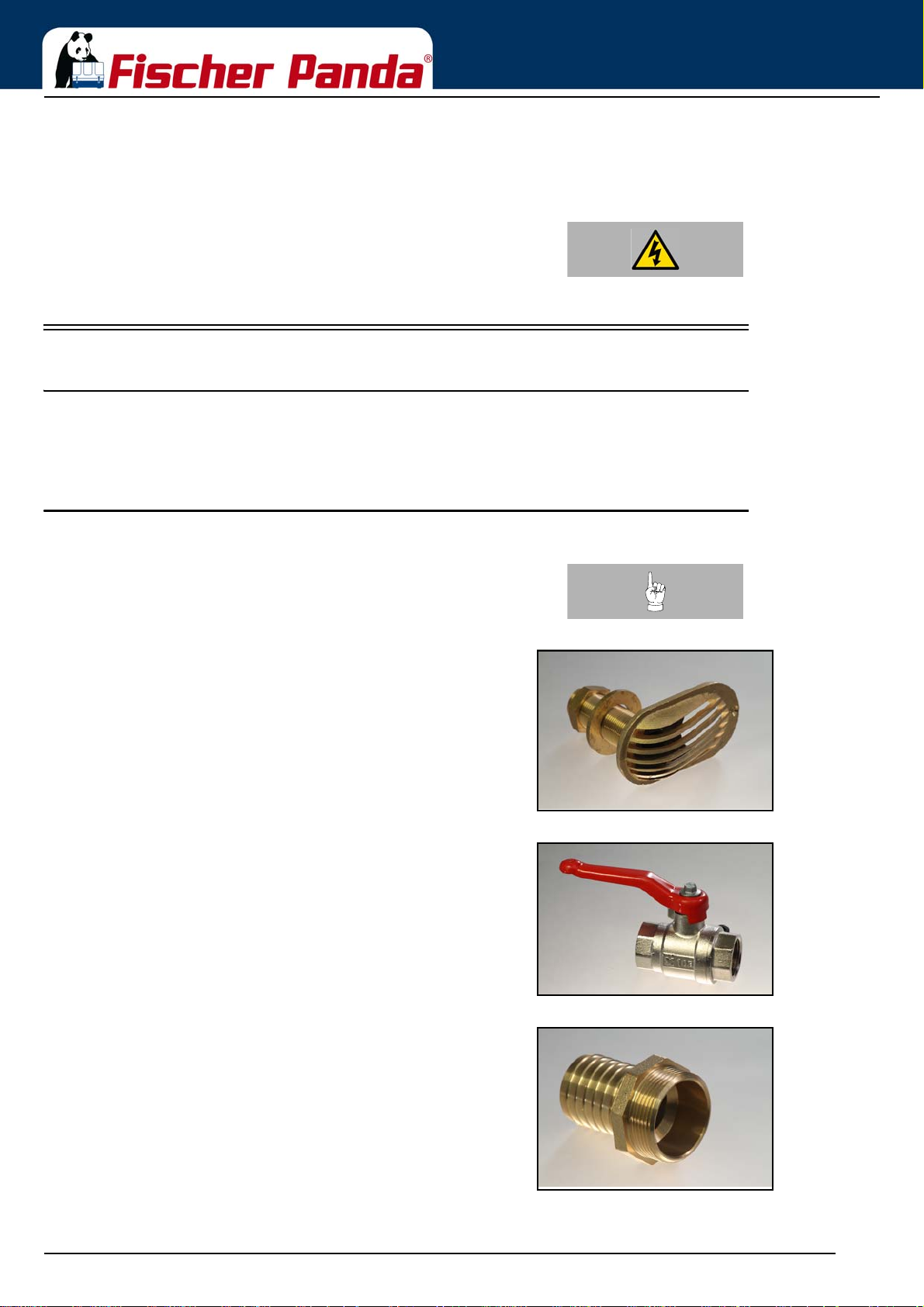
Installation Instructions
The electrical connections MUST be carried out according to the respective valid regulations. This also concerns
used cable materials. The cable supplied is meant for laying „protected“ ( i.e. in pipe) at a temperature up to a max of.
70 ° C (160 ° F). The on-board circuit must also be fitted with all essential fuses.
ATTENTION! Before working (installation) on the System read the
section „Safety Instructions“ in this Manual.
6.4 Installation of the cooling system - raw water
6.4.1 General information
The genset should have its own raw water (coolant water) inlet and should not be connected to any other engine
systems. Ensure that the following installation instructions are complied with:
6.4.2 Fischer Panda installation kit - raw water
the specified installation. You can purchase them as an
installation kit or separately at Fischer Panda.
Note:The following additional components will be required for
Fig. 6.4.2-1: Thru hull fitting with strainerThrough hull fitting with strainer
Fig. 6.4.2-2: Sea cockSea cock
Fig. 6.4.2-3: AdapterAdapter
Seite/Page 58 - Kaptitel/Chapter 6: Installation Instructions 18.12.15
Page 59
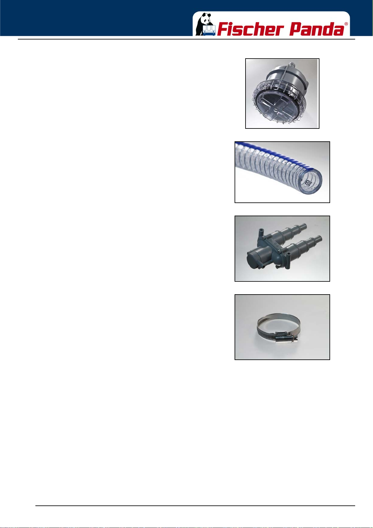
Installation Instructions
Fig. 6.4.2-4: Raw water filterRaw water filter
Fig. 6.4.2-5: Spiral coiled tube with metal spiral beadSpiral coiled tube with metal spiral bead
Fig. 6.4.2-6: Ventilation valveVentilation valve
Fig. 6.4.2-7: Hose clampsHose clamps
18.12.15 Kapitel/Chapter 6: Installation Instructions - Seite/Page 59
Page 60
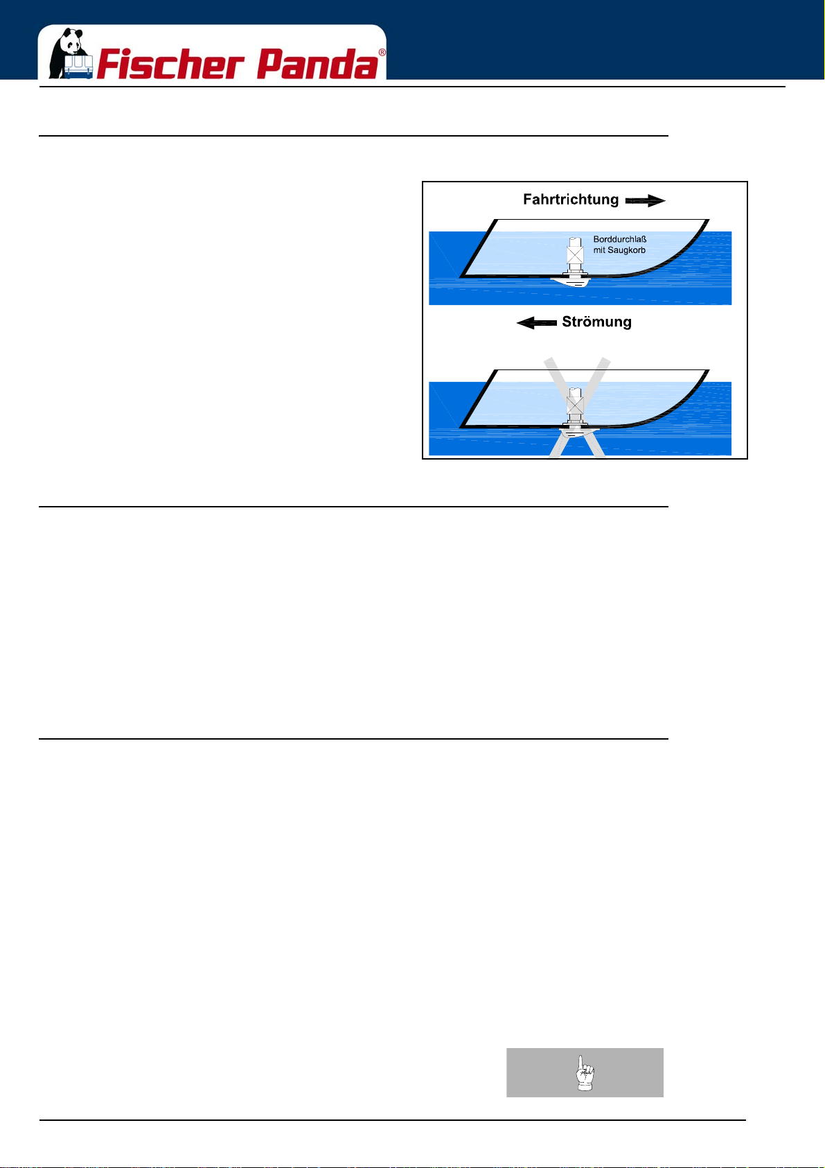
6.4.3 Installation of the through hull fitting in Yachts - scheme
Fig. 6.4.3-1: Position of the through hull fitting It is good practice for yachts t o use a throu gh hull fittin g
with an integrated strainer. The through hull fitting (raw
water intake) is often mounted against the sailing
direction to induce more water intake for cooling.
For Panda generators, the through hull inlet should NOT
point in the sailing direction! When sailing at higher speeds
more water will be forced into the inlet than the pump can
handle and your generator will flood.
Installation Instructions
6.4.4 Quality of the raw water sucking in line
In order to keep the suction resistance in the line at a minimum, the raw water intake system must have an inner
diameter of at least 1" (25 mm).
This applies also to installation components such as through-hull fitting, sea cock, raw water filter etc.
The intake suction line should be kept as short as possible. Install the raw water inlet in close proximity to the
genset.
After start-up the cooling water quantity must be measured (e.g. by catching at the exhaust). The flow rate,
as well as the necessary cross section of the cooling water pipe see section 9.10, “Diameter of conduits,”
on page 207
6.4.5 Generator installation above waterline
The Panda is equipped with a water intake pump mounted on the motor. Since the intake pump is an impeller pump
there are wearing parts which are likely to require replacement after a period of time. Ensure that the genset is
installed so that the intake pump can be easily accessed. If this is not possible, an external intake pump could be
installed in an easily accessible location
If the generator is installed above the waterline, it is possible that the impeller will wear out faster, because after
starting, the pump runs dry for some seconds. The raw water ho se should form a loop as near as possib le to the raw
water inlet of the generator (see picture below). This ensures the pump only sucks in air for a short time. The
impeller pump will be lubricated by raw water and the impeller life span will be increased.With the installation of a
non return valve in the raw water inlet line, which is under the waterline, this problem can be restricted.
When starting the generator you should always consider when raw water runs out of the exhaust system. If this
takes longer than 5 seconds you should replace the impeller pump because it sucks in air for too long before it
delivers raw water. The impeller has lost its effect and cannot suck in raw water anymore. This results to an
overheating of the motor. If the impeller is not exchanged early enough the impeller blades may break into pieces
and plugging the cooling water cycle. It is very important to exchange the impeller after a couple of months.
NOTE:If the raw water line is too long for the impeller pump or the
generator installed too high above the water line a electrical
pump can be installed into the raw water line. In this case the
impeller should be removed out of the impeller pump.
Seite/Page 60 - Kaptitel/Chapter 6: Installation Instructions 18.12.15
Page 61

Installation Instructions
Contact Fischer Panda for further information.
exchanging the old pump. If the seal in g ring is def ec ti ve
within the pump, raw water runs into the sound cover of
the genset. A repair is then very expensive.
Replacement impeller and also a spare pump should always
be on board. The old pump can be sent back to Fischer
Panda for cost-effective repair.
NOTE:Never change the impeller for many years, without
18.12.15 Kapitel/Chapter 6: Installation Instructions - Seite/Page 61
Page 62
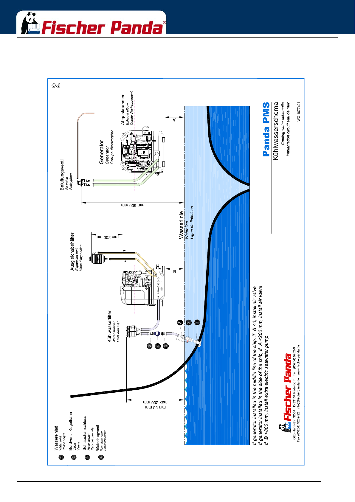
6.4.5.1 Raw water installation scheme
Fig. 6.4.5.1-1: Raw water installation schema
Installation Instructions
Seite/Page 62 - Kaptitel/Chapter 6: Installation Instructions 18.12.15
Page 63
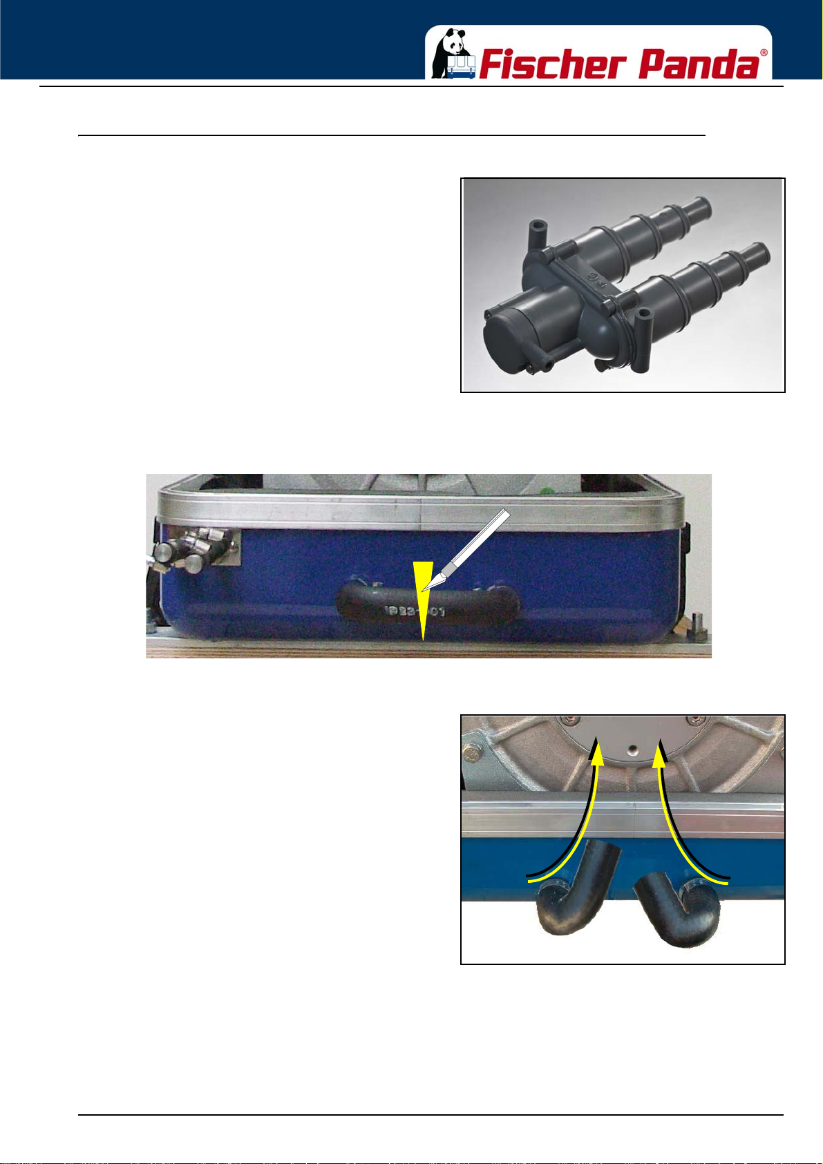
Installation Instructions
6.4.6 Generator installation below waterline
above the waterline, a vent valve must be installed at the
raw water line.
Possible heeling must be taken into consideration if installed
at the "mid-ship line"! The water hose for the external vent
valve is located at the back of the sound insulated capsule.
This hose is split in the middle and extended respectively at
each end by an additional hose and a connecting nipple.
Both hose ends must be led outside of the sound cover, if
possible 600 mm over the waterline in the mid-ship line. The
valve is connected at the highest place to the two hose ends.
If the valve jams the cool water line cannot be de-aerated
after stopping the generator, the water column is not
discontinued and water can penetrate into the combustion
chamber of the engine. This will lead to damage the engine in
a short term!
Fig. 6.4.6-1: Vent valveIf the generator cannot be attached at least 600 mm
Fig. 6.4.6-2: Rubber hose for vent valve - example
The rubber hose for the external vent valve wi ll be cu t.. .
Both hose ends will be extended respectively with a
hose and connected with a vent valve 600 mm over the
waterline.
Example
Fig. 6.4.6-3: Split rubber hose for vent valve ...and bend upwards.
18.12.15 Kapitel/Chapter 6: Installation Instructions - Seite/Page 63
Page 64
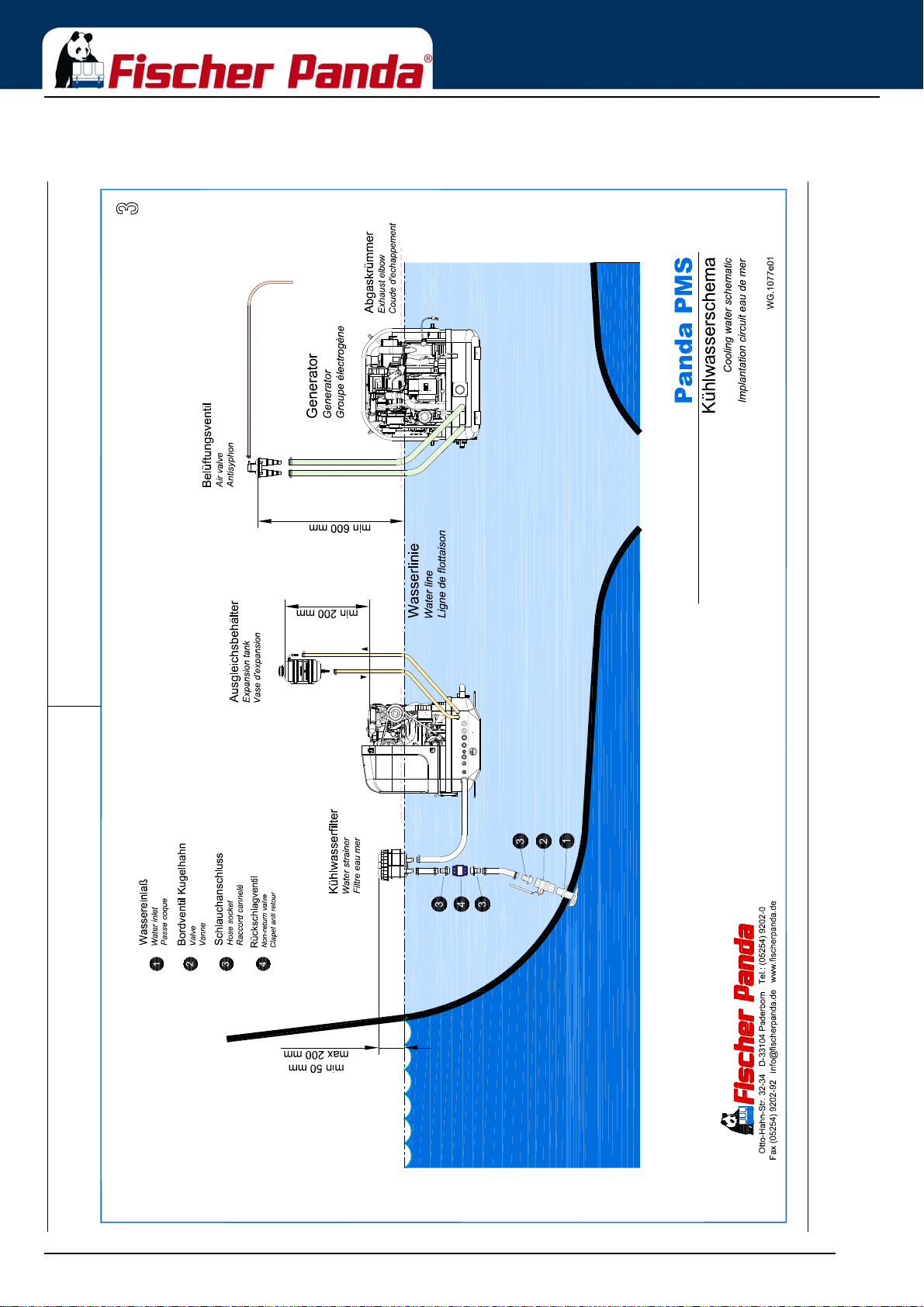
6.4.6.1 Raw water installation scheme
Fig. 6.4.6.1-1: Raw water installation schema
Installation Instructions
Seite/Page 64 - Kaptitel/Chapter 6: Installation Instructions 18.12.15
Page 65
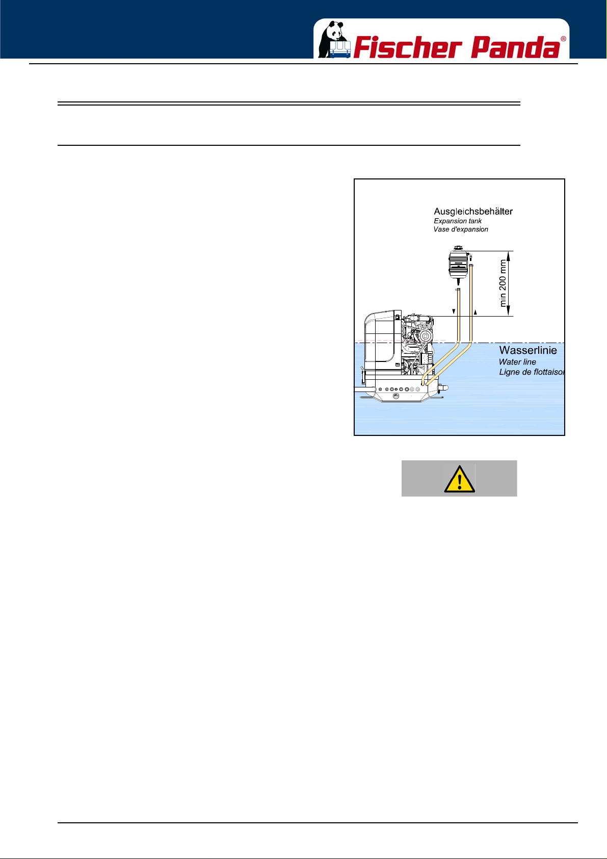
Installation Instructions
6.5 Installation of the cooling system - fresh water
6.5.1 Position of the external cooling water expansion tank
The Panda generator is normally supplied with an additional,
external cooling water expansion tank. This tank must be
installed in such a way that its lower edge is at least 200 mm
more highly arranged than the highest point of the Gene rato r.
If this 200 mm should be fallen below, i.e. the cooling water
expansion tank is lower installed, very large problems can
occur with filling and ventilating. Extend and displace the
hose lines to the outside or possibly even up to the deck.
Fig. 6.5.1-1: Position of the external cooling water expansion tankPosition of the external cooling water expansion tank
only up to the lower edge of the lower tension tape (see
note „max“) in the maximum filling level in cold
condition.
ATTENTION!The external cooling water expansion tank may be filled
18.12.15 Kapitel/Chapter 6: Installation Instructions - Seite/Page 65
Page 66
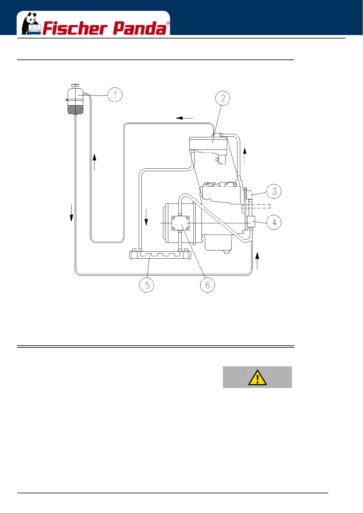
6.5.2 Scheme for freshwater circuit at two circuit cooling system
1. Expansion tank
2. Exhaust manifold
3. Thermostat housing
4. Fresh water pump
5. Heat exchanger
6. Cooling water connection block
Fig. 6.5.2-1: Scheme for freshwater circuit at two circuit cooling system
Installation Instructions
6.6 Ventilation of the coolant circuit / freshwater
AttentionSpecial notes for the ventilation of the cooling system
If the cooling water is drained, or if other air has entered the
cooling system, it is necessary to ventilate the cooling
system.
This ventilating procedure must be repeated several times:
The generator must be switched off before opening the
ventilating points!
Pay attention that the external coolant expansion tank is
connected with the generator by the intended
connection point.
Further it should be guaranteed that the expansion tank
is attached in sufficient height (200 m) over the level of
the generator highest point.
Seite/Page 66 - Kaptitel/Chapter 6: Installation Instructions 18.12.15
Page 67
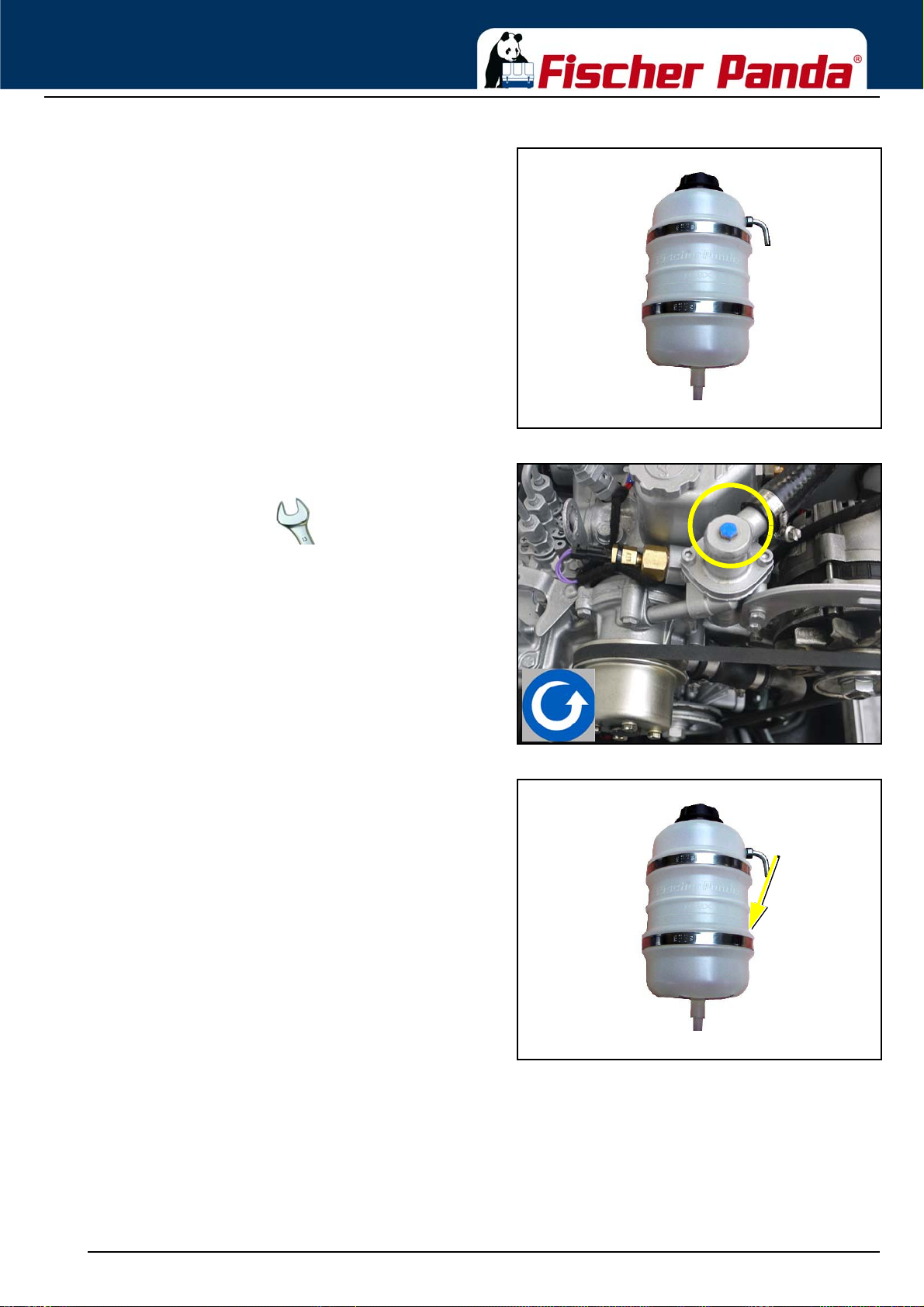
Installation Instructions
Use spanner size 10 mm.
Fig. 6.6-1: Expansion tankExpansion tank
Fig. 6.6-2: Ventilating screw on the thermostat housing7. Open the ventilating screw on the thermostat housing.
Fig. 6.6-3: filling level 20%8. Pour cooling water into the external expansion tank.
9. If the cooling water level no longer drops (the cooling
water level in cold waters must cover the tin in the
exhaust elbow), close the filler cover and the cooling
water screws and then start the generator.
10.Run the generator for approx. 60 Seconds, then switch off
11.Refill cooling water via the external expansion tank.
12.The expansion tank is connected to the generator by two
hoses.
The external expansion tank should be filled to a max 20 % in a cold state. It is very important that a larger
expansion area is maintained above the cooling water level.
13.Repeat this procedure 1 - 5 times.
If there is no change to the state of the cooling wate r level, the generator is re-started for 5 minutes. Thereafter the
de-aeration must be repeated two to three times.
Also after the first implementing a small amount of air can be reside in the cooling circuit. To ensure an immaculate
and actual operating of the cooling system the ventilating process must be repeated casual in the next few days
(weeks, if necessary). Small amount of air will still exit out of the ventilating openings, especially if the generator
18.12.15 Kapitel/Chapter 6: Installation Instructions - Seite/Page 67
Page 68

Installation Instructions
stood still for a long time.
ATTENTION! During the ventilating process repeated checks must be
made to check the cooling water is indeed circulating. If
there are air bubbles in the internal cooling water pump,
it could be that the cooling water is not circulating. The
generator will heat up very quickly and switch off,
because of overheating.
Anti-freeze
In the interest of safety, the freezing point of the closed circuit coolant should be checked on a r egular basis. Be sure
that the coolant/antifreeze mixture is good for at least -15°C (5 ° F) and if it is possible that your genset experiences
lower temperatures, for exam ple during st orage or tran sportation, then th e entire coo ling system shou ld be draine d
and purged
6.6.1 Pressure Test for Controlling the Cooling Water Circuit
Check if a temperature difference exists between cooling water in-flow and cooling water return flow by use of the
hand.
Feel the cooling water in-flow line at the internal cooling water pump.
Feel the cooling water return pipe either at the outlet of the water-cooled exhaust elbow union or at the side, where
this pipe exits at the heat exchanger.
The temperature difference between in-flow and return should be approximately 10 degrees.
Seite/Page 68 - Kaptitel/Chapter 6: Installation Instructions 18.12.15
Page 69
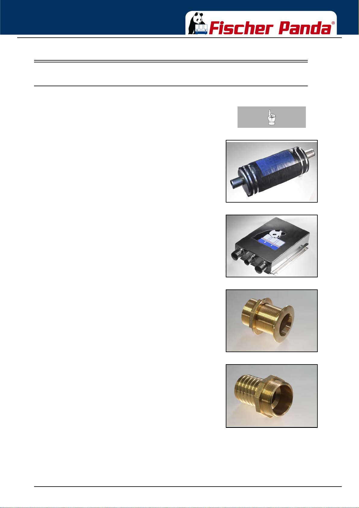
Installation Instructions
6.7 Installation of the water cooled exhaust system
6.7.1 Fischer Panda installation kit - Exhaust System
Note:The following additional components will be required for
the specified installation. You can purchase them as an
installation kit or separately at Fischer Panda.
Fig. 6.7.1-1: WaterlockWaterlock
Fig. 6.7.1-2: Exhaust Water seperatorExhaust-Water-Seperator
Fig. 6.7.1-3: Through hull fitting without strainerThrough hull fitting without strainer
Fig. 6.7.1-4: AdapterAdapter
18.12.15 Kapitel/Chapter 6: Installation Instructions - Seite/Page 69
Page 70
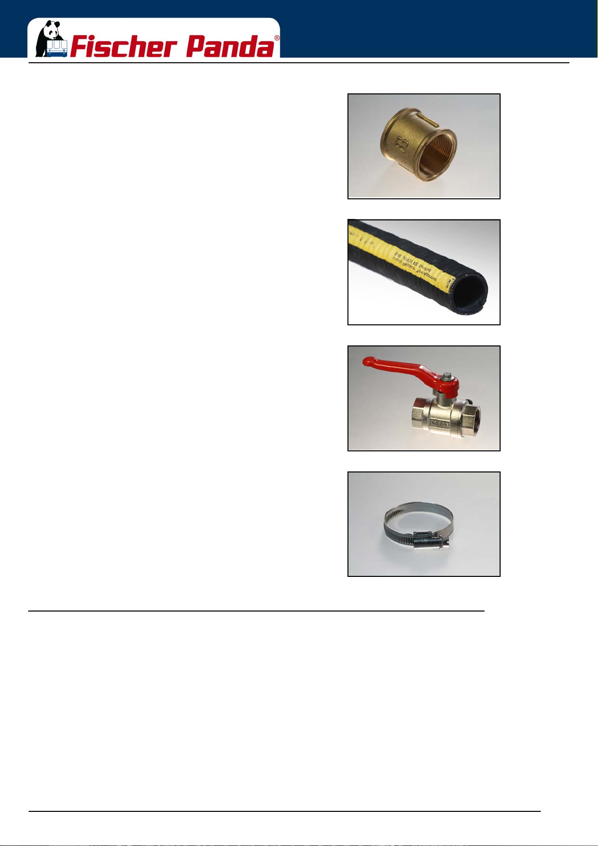
Installation Instructions
Fig. 6.7.1-5: sleeve adapter Sleeve adapter
Fig. 6.7.1-6: Exhaust hose black with wireinlayExhaust hose black with wireinlay
6.7.2 Installation of the standard exhaust system
Fig. 6.7.1-7: SeacockSeacock
Fig. 6.7.1-8: HoseclampHoseclamps
The generator exhaust system must remain completely independent and separate from the exhaust system of any
other unit(s) on board. The water lock must be installed at the lowest point of the exhaus t sy ste m . An op tio n al n oi se
insulated water lock can also be installed. The exhaust hose descends from the capsule to the water lock. Then the
hose rises via the „goose neck“ to the silencer (see drawing). The goose neck must be vertical and sit preferably
along the ship's keel centre line. In order that the back pressure inside the exhaust is not to high, the total length of
the exhaust system should not exceed 6,3 m.
By injecting the outlet raw water into the exhaust manifold, the exhaust gases are cooled and the noise emissions
from the exhaust system are reduced.
Exhaust diameter see section 9.10, “Diameter of conduits,” on page 207.
Seite/Page 70 - Kaptitel/Chapter 6: Installation Instructions 18.12.15
Page 71
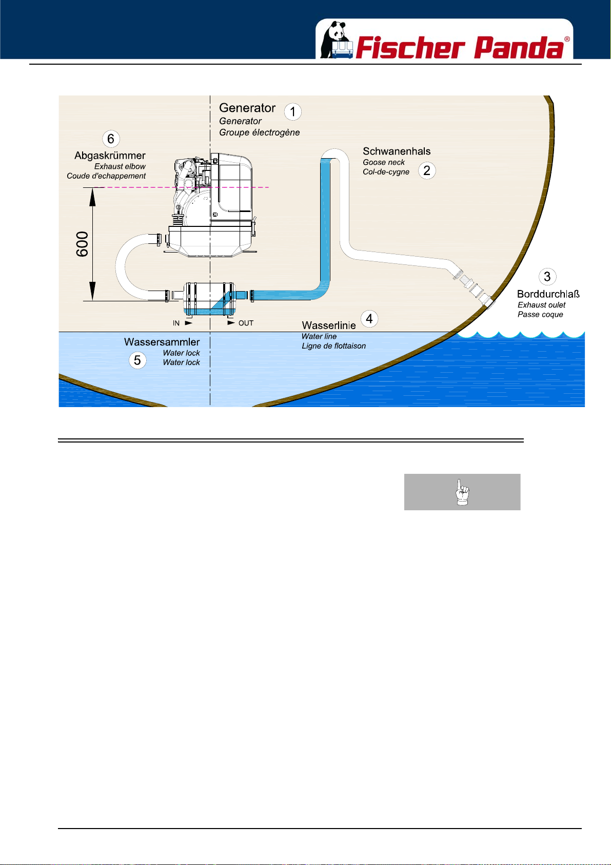
Installation Instructions
Fig. 6.7.2-1: Installation Scheme Standard Exhaust System
6.8 .Installation of the waterlock
Note!:Pay attention to the right flow direction throught the
waterlock.
Unfortunately , it can occasionally occu r that, because of an disa dvant ageous mountin g position of the waterlo ck, sea
water gets into the diesel engines’ combustion chamber. This disables the diesel engine by irreversible damages.
Quite frequently, this leads to discussions during which the parties involved in the yachts’ construction or the
installation of the generator have to explain themselves.
One point in this situation can be clarified definitely:
If sea water gets into the inner section of the engine, this is not possible due to constructional defects of the
generator or to malfunctions on the engine itself. It can only reach the combustion chamber via the exhaust hose
and thus get into the engine.
Thereby, the position of the generator and the waterlock, as well as the arrangement of the cooling water and
exhaust hoses play the decisive role.
If the waterlock is arranged in an unfavourable position, the cooling water flowing back in the exhaust hose can rise
so high, that it reaches the exhaust stack. Since at least one discharge valve is always op en when the engine is shut
off, the sea water has free access to the combustion chamber. By capillary action, this sea water then flows past the
cocks and even reaches the engine oil in that way. (In fact, a surprisingly high oil level is a first indication of an
upcoming catastrophe).
If an usual high oil level can be detected and/or the oil is of a greyish colour, the engine must not be used
anymore. This is a certain sign for cooling wat er that got int o the oil pan. If the engine is started under these
conditions, the water and the oil are mixed into an emulsion. The oil will quickly become so viscous that one
will have to call it a paste. In this phase the fine oil hoses are blocked and a few moments later the machine
gets destroyed because of insufficient lubrication. Before this happens, an immediate oil change should be
made. Since the water can only reach the engine via the combustion chamber, it can be assumed that the
compression rings will start to corrode. These effects have to be discussed with an engine expert. It will
18.12.15 Kapitel/Chapter 6: Installation Instructions - Seite/Page 71
Page 72

Installation Instructions
certainly be reasonable to immediately inject plenty penetrating oil through the intake stack and to slowly
turn the engine with the starter motor.
The cooling water can reach the exhaust area via the exhaust hose as well as via the cooling water feed.
6.8.1 Possible cause for water in the exhaust hose
6.8.1.1 Possible cause: exhaust hose
If the cause is the exhaust hose itself, the following points are to be checked at the hose:
a) Position of the waterlock is too high. The water reaches the exhaust hose.
b) Positio n of the waterl ock is too far away fr om th e middle of the generator. The water reaches the exhaust hose in
tilted position.
c) The waterlock is too small relating to the length of the exhaust hose.
6.8.1.2 Possible cause: cooling water hose
If the generator is not clearly installed 600 m m over the wat er line, the coo ling water feed m ust be equippe d with a
„venting valve“ which is at least led out 600 mm over the water lin e. (This position must also be assu red in every
tilted position. Therefore, the venting valve should be located in the ships’ center line, so that it cannot move in tilted
position).
a) Position of the venting valve is too low. The water flo ws into the exhaust area when the ship is tilted.
b) Position of the venting valve is too far from the ships’ center line. The water reaches the exhaust area when the
ship is tilted.
c) The venting valve does not work, because it jams or it is clotted. (The venting valve’s function needs to be
checked regularly.)
As it consistently happens that functioning risks are not realised during the laying of the exhaust hose, the following
explanations refer explicitly to the exhaust hose. Here, the location, the size and the position of the „wat erlock “ play
a very decisive role:
6.8.2 Installation area of the waterlock
Concerning a water-cooled exhaust system, it must be regarded that - under no circumstances - cooling water from
the exhaust hose can get into the exhaust elbow area at the engine. If this happens, the cooling water can get into
the combustion chamber via an open discharge valve. This would lead to irreparable damage at the engine.
In addition to that, one has to reckon with poss ible tilted positions of sailing yachts, which makes the position of the
waterlock even more important. In general one could say that:
The deeper the waterlock is located underneath the generator, the better th e pr otec tio n from entering water into the
combustion chamber.
The picture below shows that the distance between the critical point at the exhaust elbow and the maximum
permissible water level in the exhaust hose is stated with 600 mm. This distance should be understood as a
minimum distance.
Seite/Page 72 - Kaptitel/Chapter 6: Installation Instructions 18.12.15
Page 73
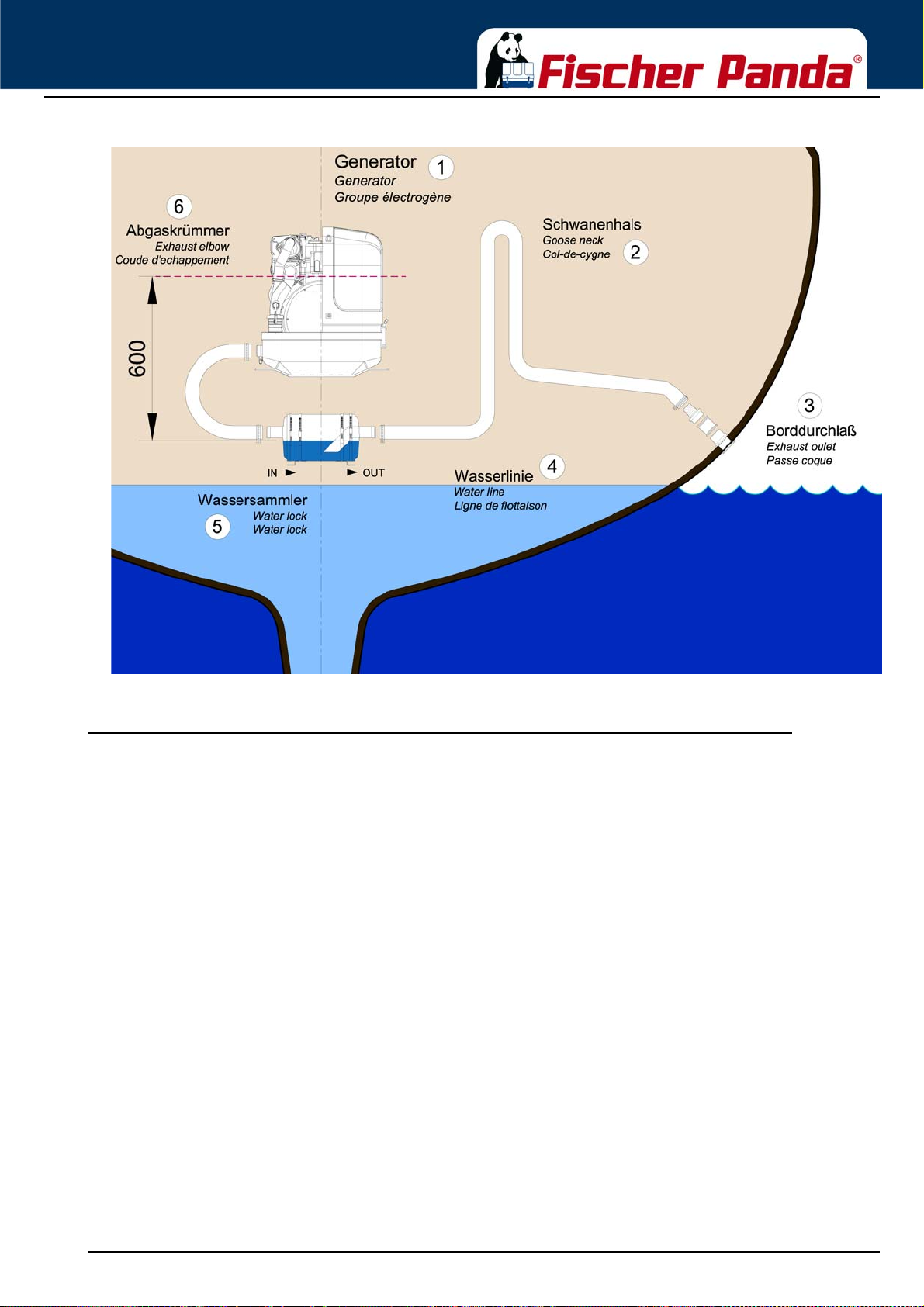
Installation Instructions
Fig. 6.8.2-1: Installation area of the waterlock
6.8.3 The volume of the waterlock
The waterlock must be measured so large, that it can take the entire amount of water flowing back from the exhaust
hose. The amount of water depends on the hoses’ length (L) and its cross section. While the diesel engine is
running, cooling water is continuously injected into the exhaust system and is carted outside with the emissions by
the exhaust gas pressure. When the engine is turned off, the number of revolutions sinks quite fast. By doing so, the
point is reached where the exhaust gas pressure does not suffice anymore to cart the cooling water out. All cooling
water remaining in the hose at that point flows back into the waterlock. At the same time, the diesel engine itself
continues to cart cooling water through the cooling water pump, as long as it keeps on rotating.
The waterlock must necessarily be measured large enough that it can take the entire amount of cooling
water and, at the same time, does not exceed the prescribed vertical height of 600 mm up to the critical
point at the exhaust elbow.
18.12.15 Kapitel/Chapter 6: Installation Instructions - Seite/Page 73
Page 74
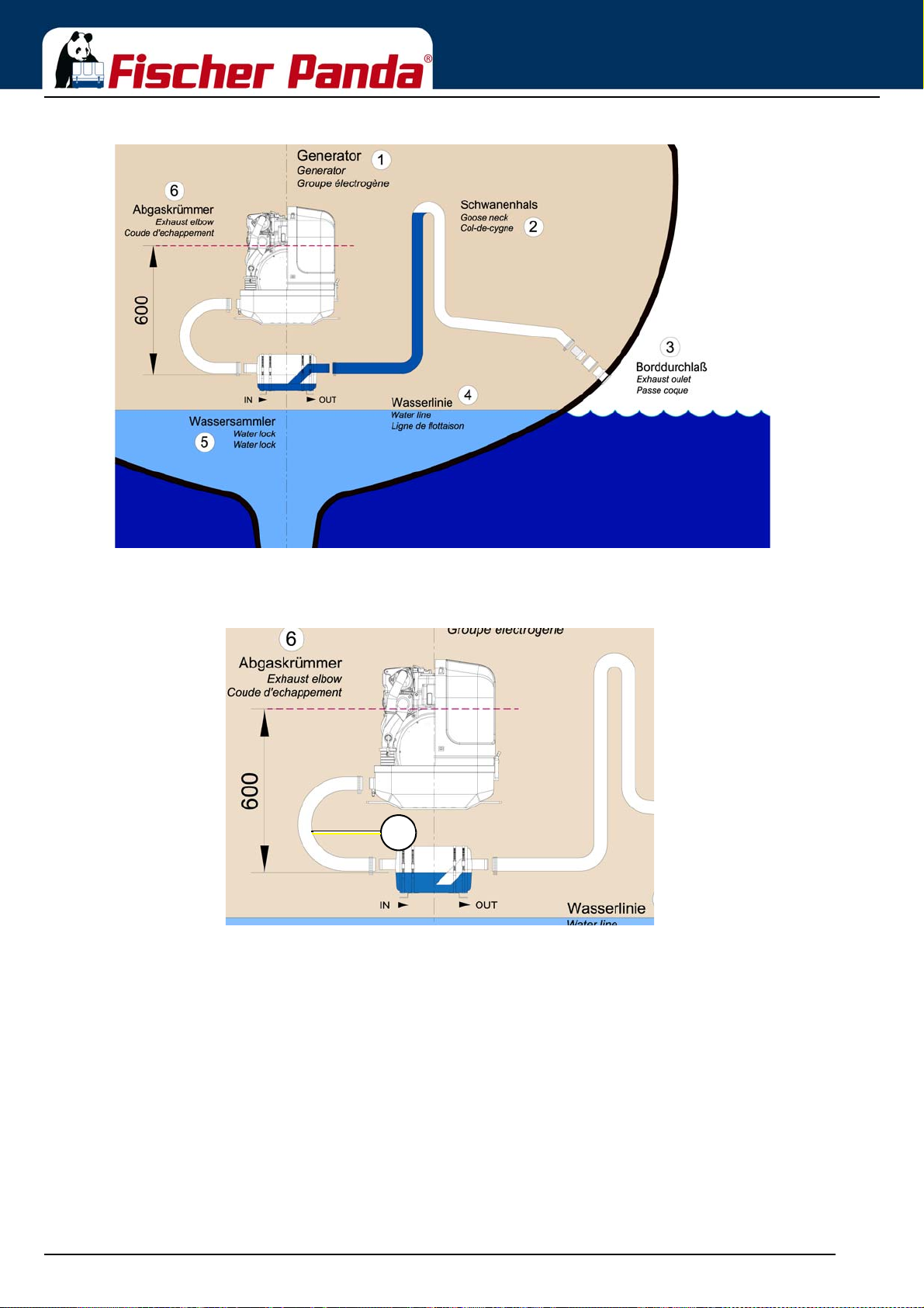
Fig. 6.8.3.0-1: Volume of the waterlock
1
Installation Instructions
If there are any doubts, a verification can easily be made by temporarily using a clear-sighted hose (1) as exhaust
hose. In that way, the cooling water level can be checked very easily.
Fig. 6.8.3.0-2: Testing the cooling water level
Seite/Page 74 - Kaptitel/Chapter 6: Installation Instructions 18.12.15
Page 75
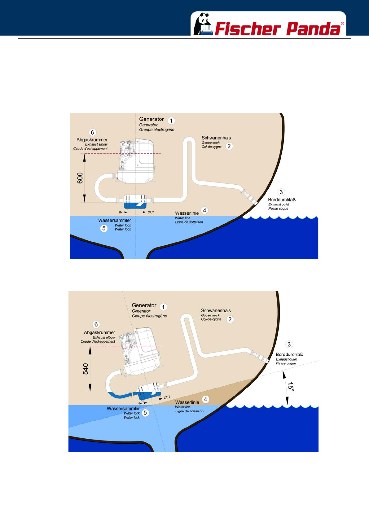
Installation Instructions
6.8.3.1 Ideal position of the waterlock
Important Note!
The ideal position of the waterlock would be in center underneath the generator. Only in this position it is
assured that the water level cannot change drastically in tilted position by the waterlock moving out of the
center line. See the following pictures:
Fig. 6.8.3.1-1: Ideal position of the waterlock
In Fig. 6.11.3.1-1, the waterlock is mounted in center underneath the generator. When the ship tilts, the position of
the waterlock related to the critical point at the exhaust hose, changes only slightly.
Fig. 6.8.3.1-2: Tilted position 15 degrees
Tilted position 15 degrees - Fig. 6.11.3.1-2
The distance from the exhaust elbow to the hydrostatic head has derated to 540 mm.
18.12.15 Kapitel/Chapter 6: Installation Instructions - Seite/Page 75
Page 76
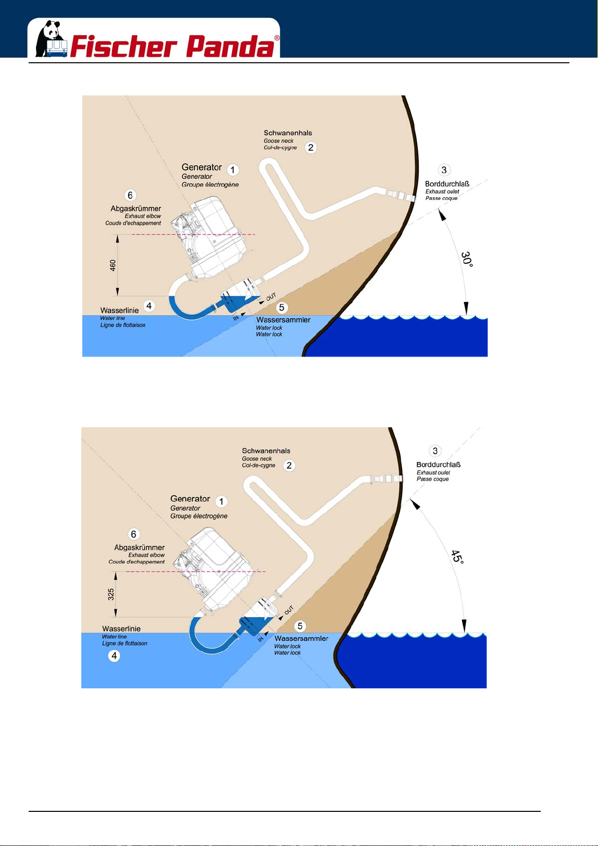
Fig. 6.8.3.1-3: Tilted position 30 degrees
Installation Instructions
Tilted position 30 degrees - Fig. 6.11.3.1-3
The distance of the water level, even in ideal position , changes that only 458 mm distance remain. So the crit ical
distance is under-run already.
Fig. 6.8.3.1-4: Tilted position 45 degrees
Tilted position 45 degrees - Fig. 6.11.3.1-4
In this case the water level rise so high, that the distance constitutes only 325 mm.
Even when the water lock is mounted in the ideal spot, at an extremely tilted position of 45 degrees there is still the
risk that water can get straight into the discharge stack area throug h strong rocking motion s („slos hing“). This sh ows
that the distance of 600 mm represents a minimum size at which, even when installed ideally, the water can slosh
into the exhaust elbow when the ship is very tilted or rocks very hard.
Seite/Page 76 - Kaptitel/Chapter 6: Installation Instructions 18.12.15
Page 77

Installation Instructions
Summary:
The preset minimum height of 600 mm must be regarded unconditionally and is only valid if the waterlock is
mounted in its ideal position in center underneath the generator. A higher position is highly recommended if it has to
be reckoned with tilted positions of 45 degrees.
18.12.15 Kapitel/Chapter 6: Installation Instructions - Seite/Page 77
Page 78
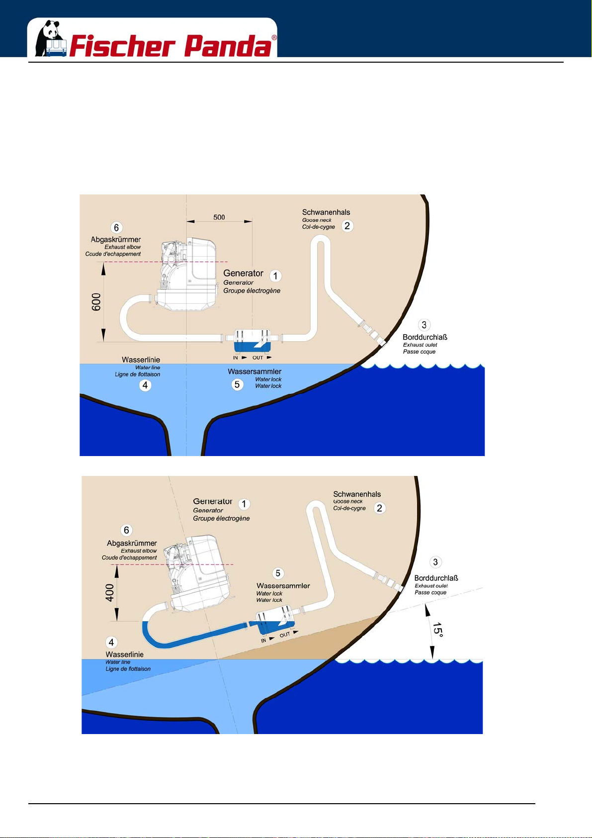
Installation Instructions
6.8.3.2 Example of the installation of the waterlock off-center and possible effects:
The following pictures are primarily relevant for an installation of the generator with the waterlock on sailing yachts.
A change in the mounting position caused by tilted position does not have to be reckoned concerning motor yachts.
Here it is only necessary to regard that the volume of the waterlock is measured so large that it can take the entire
amount of water flowing back, and at the same time, maintains the minimum distance of 600 mm.
A) Installation of the waterlock 500 mm next to the generator’s center line:
Fig. 6.8.3.2-1: waterlock, 500 mm next to the center line
Fig. 6.8.3.2-2: Tilted position, 15 degrees
Tilted position 15 degrees - Fig. 6.11.3.2-2
The distance is only 404 mm instead of the original 600 mm. So this is very close to the critical point.
Seite/Page 78 - Kaptitel/Chapter 6: Installation Instructions 18.12.15
Page 79
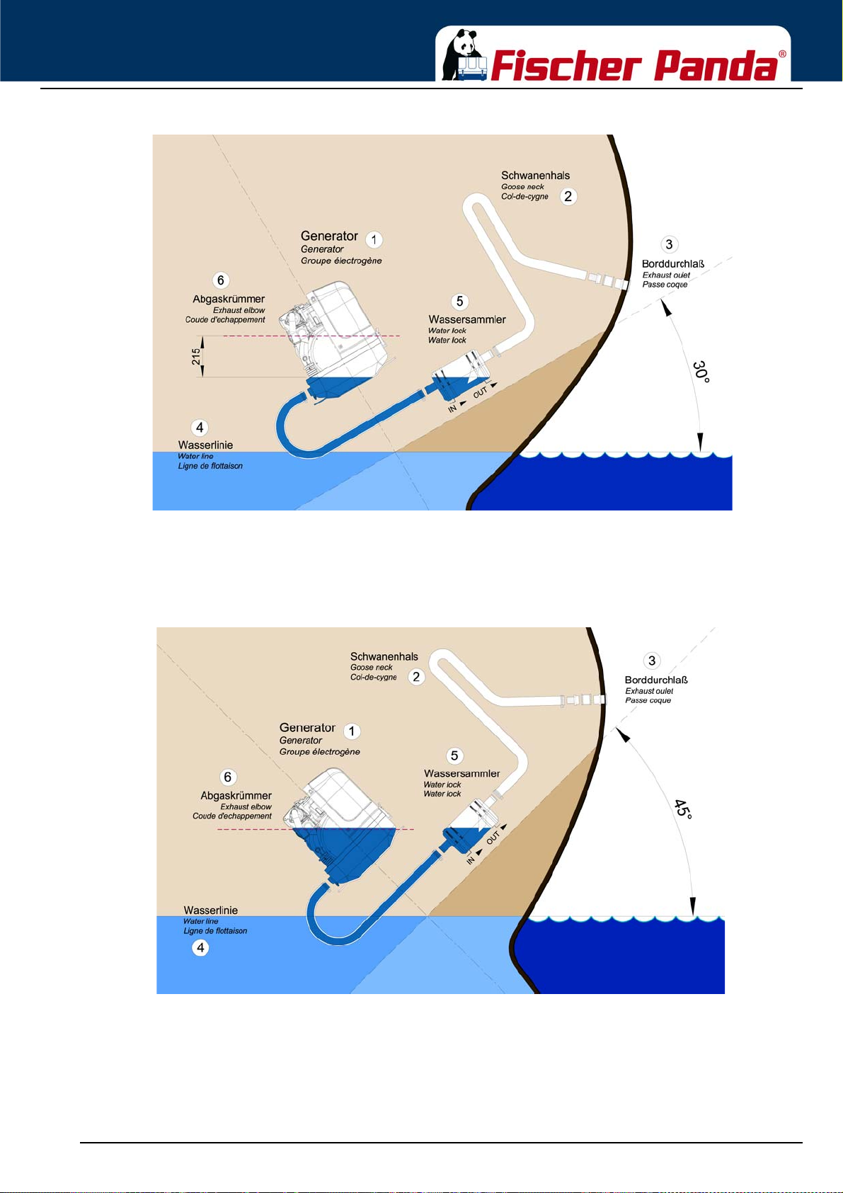
Installation Instructions
Fig. 6.8.3.2-3: Tilted position 30 degrees
Tilted position 30 degrees - Fig. 6.11.3.2-3
The distance between the hydrostatic head and the critical point at the exhaust elbow is only 216 mm. This means
that in a tilted position of 30 degrees you already face the highest risk of sea water sloshing into the combustion
chamber.
Fig. 6.8.3.2-4: Tilted position 45 degrees
Tilted position 45 degrees - Fig. 6.11.3.2-4
The water level is now at the same height as the critical point at the exhaust elbow. If the ship is sailed in a tilted
position of 45 degrees with an installation like this, the ingress of cooling water into the combustion chamber is
inevitable. Irreparable damages are pre-programmed.
18.12.15 Kapitel/Chapter 6: Installation Instructions - Seite/Page 79
Page 80
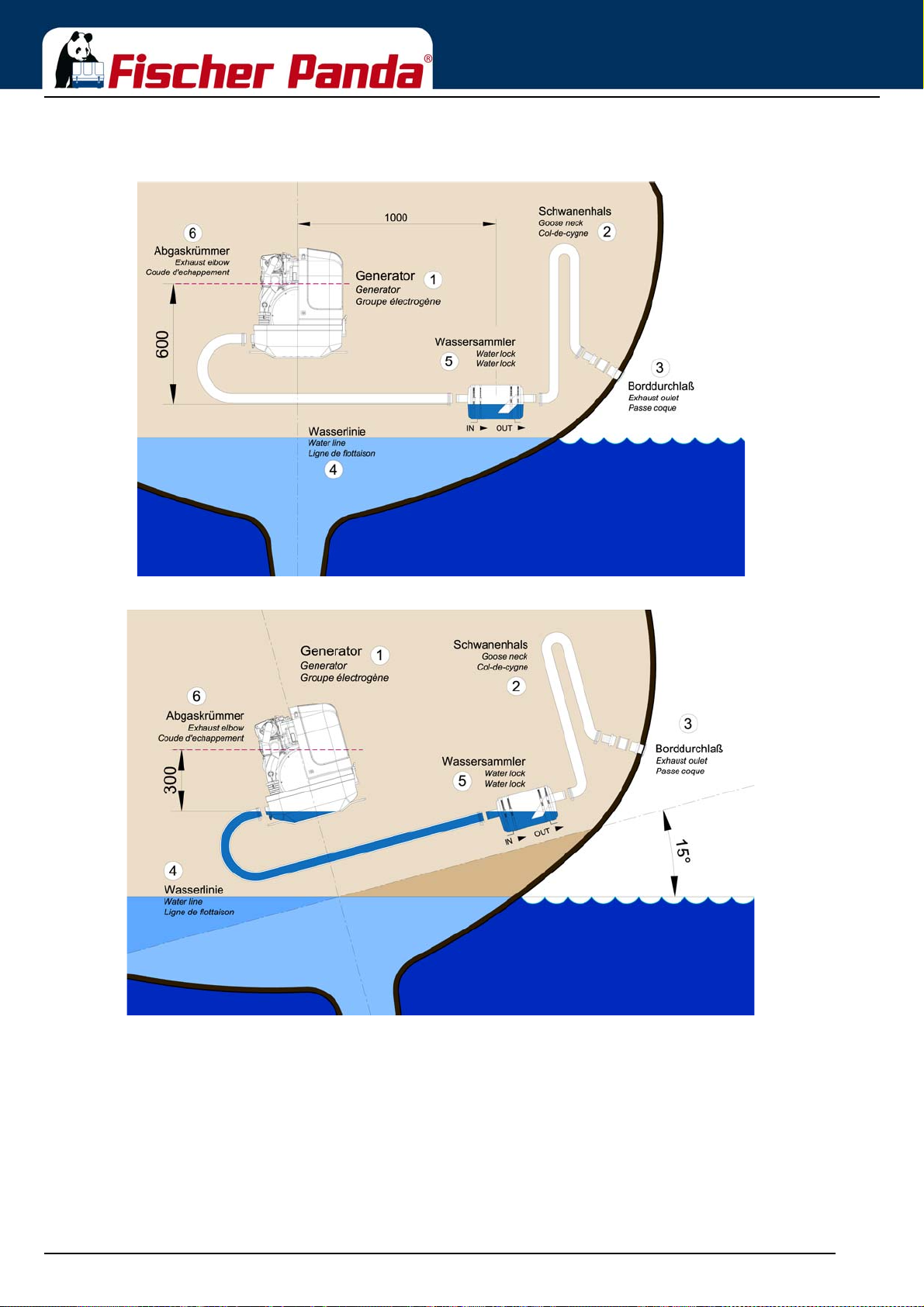
B) Installation distance between waterlock and the generator’s center line 1000 mm
Fig. 6.8.3.2-5: waterlock, 1000 mm next to center line
Installation Instructions
Fig. 6.8.3.2-6: Tilted position 15 degrees
Tilted position 15 degrees - Fig. 6.11.3.2-6
The distance is, contrary to the original 600 mm, only 327 mm. This is very close to the critical point already.
Seite/Page 80 - Kaptitel/Chapter 6: Installation Instructions 18.12.15
Page 81
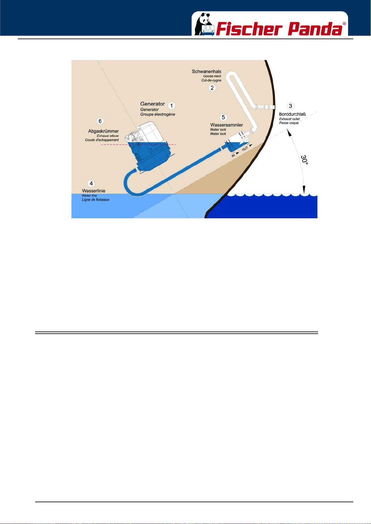
Installation Instructions
Fig. 6.8.3.2-7: Tilted position 30 degrees
Tilted position 30 degrees - Fig. 6.11.3.2-7
The water level and the critical point at the exhaust elbow are at the same level now. If the ship is sailed in a tilted
position of 30 degrees with an installation like that, the infiltration of cooling water into the combustion chamber is
inevitable. Irreparable damages are pre-programmed.
Summary:
Concerning sailing yachts it must be regarded, that the waterlock is mounted in center underneath the generator, at
least in reference to the ships’ center line. Thus the waterlock is prevented from „leaking“ very strongly when the
ship is tilted.
The „leaking“ of the waterlock leads to a rise of the water level which then gets too close to the exhaust elbow’s
critical point.
6.9 Exhaust / water separator
In order to reduce the noise level of the generator unit to a minimum, an optional exhaust outlet muffler can be
mounted next to the through-hull fitting. Additionally there is a component at Fischer Panda, which acts as both an
„exhaust goose neck“, and water separator. With this „exhaust/water separator“ the cooling water is derived over a
separate pipe. The exhaust noises emanating from the exterior of the yacht are strongly decreased. Particu larly the
„water splash“.
18.12.15 Kapitel/Chapter 6: Installation Instructions - Seite/Page 81
Page 82
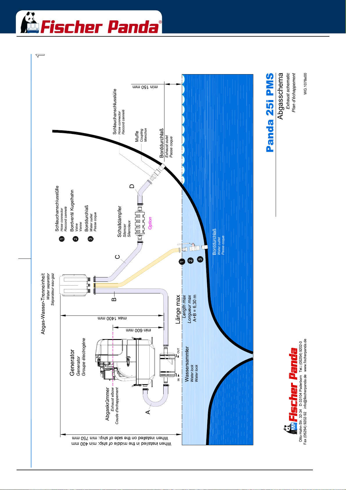
Fig. 6.9.0-1: Installation Scheme exhaust / water separator
Installation Instructions
Seite/Page 82 - Kaptitel/Chapter 6: Installation Instructions 18.12.15
Page 83
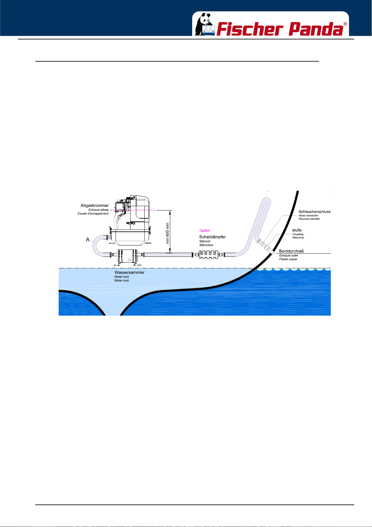
Installation Instructions
Example of an unfavourable installation:
- Water lock not far enough below the lowest level of the generator
- Distance water lock to gooseneck too large
6.9.1 Installation exhaust water separator
If the exhaust water separator was sufficiently highly installed, a goose neck is no longer necessary. The exhaust/
water separator fulfils the same function. If the „Super silent“ exhaust system were installed correctly, the generator
will not disturb your boat neighbour. The exhaust noise should be nearly inaudible. The best result is reached, if the
hose line, which derive the cooling water, is relocate on a short way „falling“ directly to the outlet and this outlet is
under the waterline.
If the through-hull exhaust outlet has to be mounted far from the generator, an exhaust-water separator must definitely be installed. The raw water from the separator must then run along the shortest possible path in the throughhull outlet. For such long exhaust routes, the exhaust hose diameter should also be increased, f.e. from NW4 0mm to
NW50mm in order to reduce the back-pressure. The exhaust may have a length of over 10 m (32 ft.) if the exhaust
hose diameter is increased. An additional outlet exhaust muffler close to the hull outlet will help further to reduce
noise emissions.
The generator will not disturb your boat neighbours, if the „Super silent exhaust system has been correctly installed.
The exhaust noise should be almost inaudible.
Fig. 6.9.1-1: Example for an unfavourable Installation
18.12.15 Kapitel/Chapter 6: Installation Instructions - Seite/Page 83
Page 84
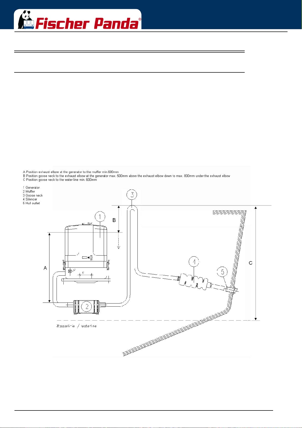
Installation Instructions
6.10 Installation of the water cooled exhaust system
6.10.1 Installation of the standard exhaust system
The generator exhaust system must remain completely independent and separate from the exhaust system of any
other unit(s) on board. The water lock must be installed at the lowest point of the exhaus t sy ste m . An op tio n al n oi se
insulated water lock can also be installed. The exhaust hose descends from the capsule to the water lock. Then the
hose rises via the „goose neck“ to the silencer (see drawing). The goose neck must be vertical and sit preferably
along the ship's keel centre line. In order that the back pressure inside the exhaust is not to high, the total length of
the exhaust system should not exceed 6 m (20 ft.)
By injecting the outlet raw water into the exhaust manifold, the exhaust gases are cooled and the noise emissions
from the exhaust system are reduced.
Exhaust diameter see section 9.10, “Diameter of conduits,”
on page 207
Fig. 6.10.1-1: Installation Scheme Standard Exhaust System
Seite/Page 84 - Kaptitel/Chapter 6: Installation Instructions 18.12.15
Page 85

Installation Instructions
6.11 .Installation of the waterlock
Note!:Pay attention to the right flow direction throught the
waterlock.
Unfortunately , it can occasionally occu r that, because of an disa dvant ageous mountin g position of the waterlo ck, sea
water gets into the diesel engines’ combustion chamber. This disables the diesel engine by irreversible damages.
Quite frequently, this leads to discussions during which the parties involved in the yachts’ construction or the
installation of the generator have to explain themselves.
One point in this situation can be clarified definitely:
If sea water gets into the inner section of the engine, this is not possible due to constructional defects of the
generator or to malfunctions on the engine itself. It can only reach the combustion chamber via the exhaust hose
and thus get into the engine.
Thereby, the position of the generator and the waterlock, as well as the arrangement of the cooling water and
exhaust hoses play the decisive role.
If the waterlock is arranged in an unfavourable position, the cooling water flowing back in the exhaust hose can rise
so high, that it reaches the exhaust stack. Since at least one discharge valve is always op en when the engine is shut
off, the sea water has free access to the combustion chamber. By capillary action, this sea water then flows past the
cocks and even reaches the engine oil in that way. (In fact, a surprisingly high oil level is a first indication of an
upcoming catastrophe).
If an usual high oil level can be detected and/or the oil is of a greyish colour, the engine must not be used
anymore. This is a certain sign for cooling wat er that got int o the oil pan. If the engine is started under these
conditions, the water and the oil are mixed into an emulsion. The oil will quickly become so viscous that one
will have to call it a paste. In this phase the fine oil hoses are blocked and a few moments later the machine
gets destroyed because of insufficient lubrication. Before this happens, an immediate oil change should be
made. Since the water can only reach the engine via the combustion chamber, it can be assumed that the
compression rings will start to corrode. These effects have to be discussed with an engine expert. It will
certainly be reasonable to immediately inje ct plenty penetrating oil through the intake stack and to slowly
turn the engine with the starter motor.
The cooling water can reach the exhaust area via the exhaust hose as well as via the cooling water feed.
6.11.1 Possible cause for water in the exhaust hose
6.11.1.1 Possible cause: exhaust hose
If the cause is the exhaust hose itself, the following points are to be checked at the hose:
a) Position of the waterlock is too high. The water reaches the exhaust hose.
b) Position of the waterlock is too far awa y from the midd le o f the ge ne rator. The water reaches the exhaust hose in
tilted position.
c) The waterlock is too small relating to the length of the exhaust hose.
6.11.1.2 Possible cause: cooling water hose
If the generator is not clearly installed 600 mm over the water line, the cooling water feed must be equipped with a
„venting valve“ which is at least led out 600 mm over the water line. (This position must also be assured in every
tilted position. Therefore, the venting valve should be located in the ships’ center line, so that it cannot move in tilte d
position).
a) Position of the venting valve is too low. The water flows into the exhaust area when the ship is tilted.
18.12.15 Kapitel/Chapter 6: Installation Instructions - Seite/Page 85
Page 86
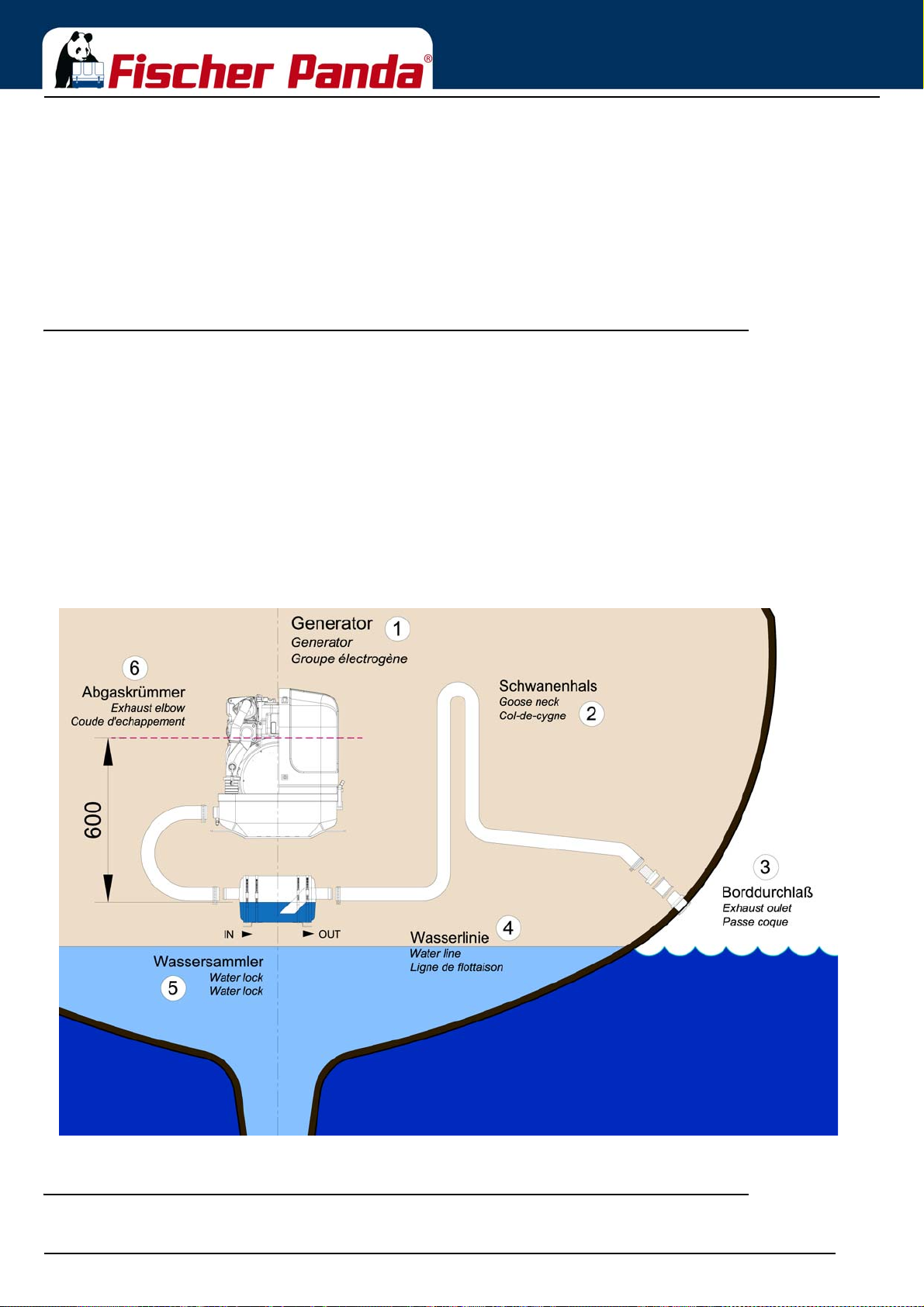
Installation Instructions
b) Position of the venting valve is too far from the ships’ center line. The water reaches the exhaust area when the
ship is tilted.
c) The venting valve does not work, because it jams or it is clotted. (The venting valve’s function needs to be
checked regularly.)
As it consistently happens that functioning risks are not realised during the laying of the exhaust hose, the following
explanations refer explicitly to the exhaust hose. Here, the location, the size and the position of the „wat erlock “ play
a very decisive role:
6.11.2 Installation area of the waterlock
Concerning a water-cooled exhaust system, it must be regarded that - under no circumstances - cooling water from
the exhaust hose can get into the exhaust elbow area at the engine. If this happens, the cooling water can get into
the combustion chamber via an open discharge valve. This would lead to irreparable damage at the engine.
In addition to that, one has to reckon with poss ible tilted positions of sailing yachts, which makes the position of the
waterlock even more important. In general one could say that:
The deeper the waterlock is located underneath the generator, the better th e pr otec tio n from entering water into the
combustion chamber.
The picture below shows that the distance between the critical point at the exhaust elbow and the maximum
permissible water level in the exhaust hose is stated with 600 mm. This distance should be understood as a
minimum distance.
Fig. 6.11.2-1: Installation area of the waterlock
6.11.3 The volume of the waterlock
The waterlock must be measured so large, that it can take the entire amount of water flowing back from the exhaust
Seite/Page 86 - Kaptitel/Chapter 6: Installation Instructions 18.12.15
Page 87
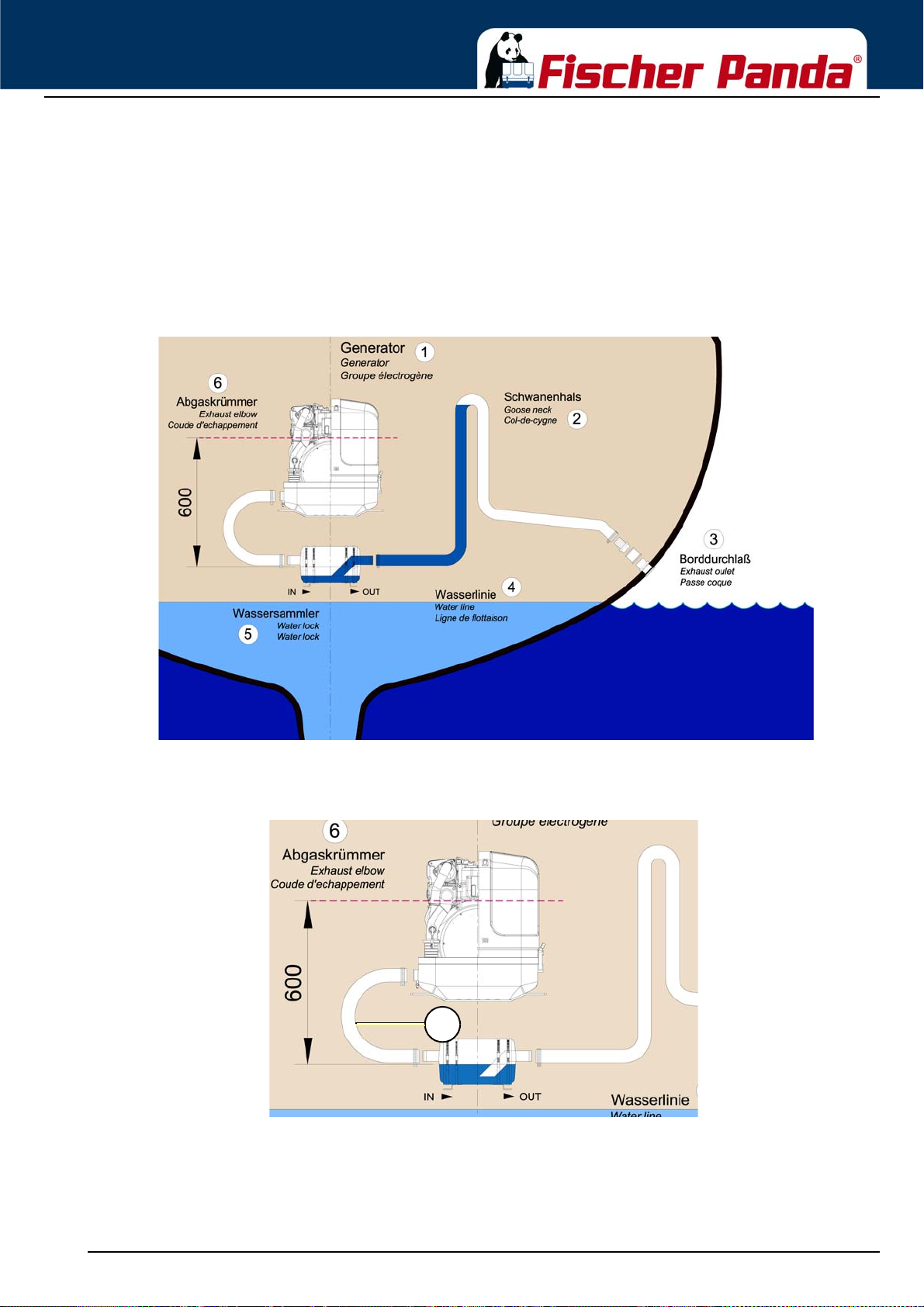
Installation Instructions
1
hose. The amount of water depends on the hoses’ length (L) and its cross section. While the diesel engine is
running, cooling water is continuously injected into the exhaust system and is carted outside with the emissions by
the exhaust gas pressure. When the engine is turned off, the number of revolutions sinks quite fast. By doing so, the
point is reached where the exhaust gas pressure does not suffice anymore to cart the cooling water out. All cooling
water remaining in the hose at that point flows back into the waterlock. At the same time, the diesel engine itself
continues to cart cooling water through the cooling water pump, as long as it keeps on rotating.
The waterlock must necessarily be measured large enough that it can take the entire amount of cooling
water and, at the same time, does not exceed the prescribed vertical height of 600 mm up to the critical
point at the exhaust elbow.
Fig. 6.11.3.0-1: Volume of the waterlock
If there are any doubts, a verification can easily be made by temporarily using a clear-sighted hose (1) as exhaust
hose. In that way, the cooling water level can be checked very easily.
Fig. 6.11.3.0-2: Testing the cooling water level
18.12.15 Kapitel/Chapter 6: Installation Instructions - Seite/Page 87
Page 88
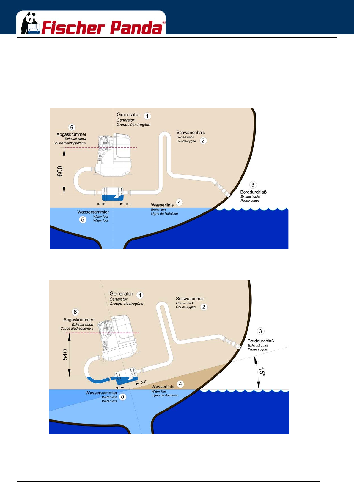
Installation Instructions
6.11.3.1 Ideal position of the waterlock
Important Note!
The ideal position of the waterlock would be in center underneath the generator. Only in this position it is
assured that the water level cannot change drastically in tilted position by the waterlock moving out of the
center line. See the following pictures:
Fig. 6.11.3.1-1: Ideal position of the waterlock
In Fig. 6.11.3.1-1, the waterlock is mounted in center underneath the generator. When the ship tilts, the position of
the waterlock related to the critical point at the exhaust hose, changes only slightly.
Fig. 6.11.3.1-2: Tilted position 15 degrees
Tilted position 15 degrees - Fig. 6.11.3.1-2
The distance from the exhaust elbow to the hydrostatic head has derated to 540 mm.
Seite/Page 88 - Kaptitel/Chapter 6: Installation Instructions 18.12.15
Page 89
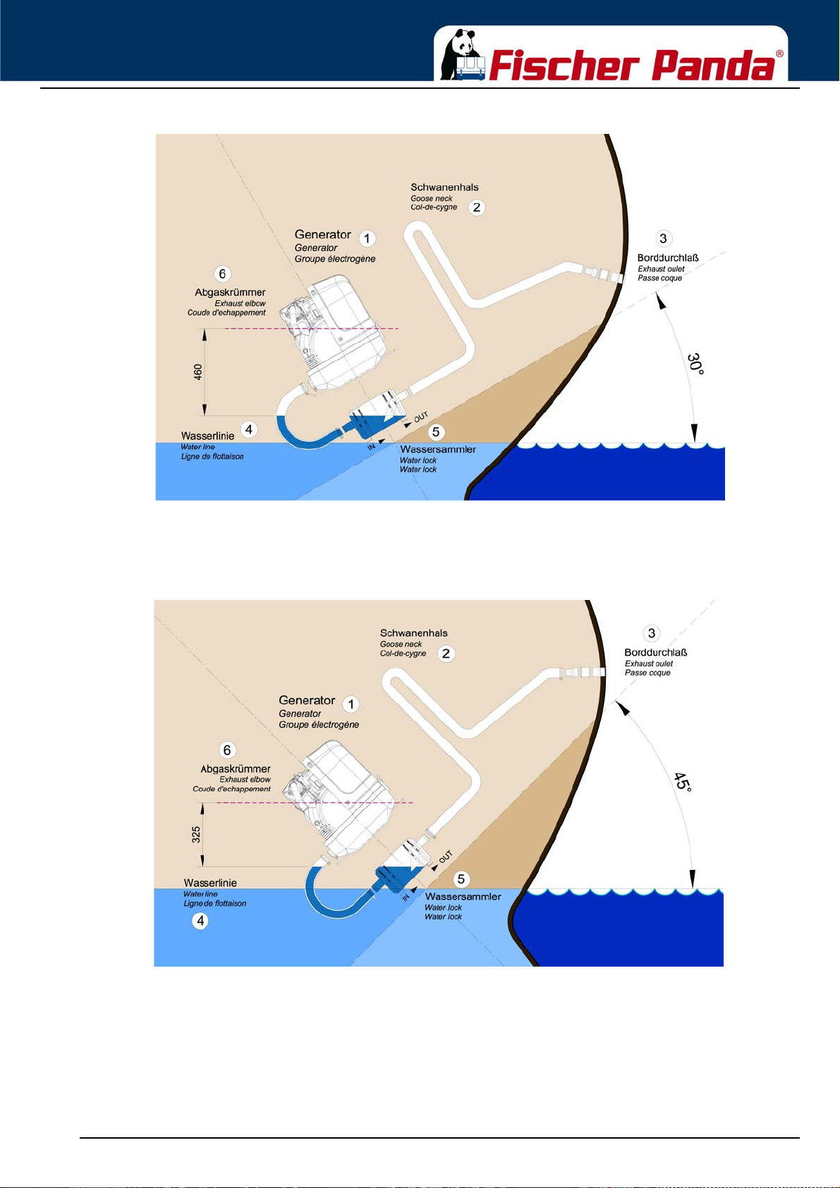
Installation Instructions
Fig. 6.11.3.1-3: Tilted position 30 degrees
Tilted position 30 degrees - Fig. 6.11.3.1-3
The distance of the water level, even in ideal position, changes that only 458 mm distance remain. So the critical
distance is under-run already.
Fig. 6.11.3.1-4: Tilted position 45 degrees
Tilted position 45 degrees - Fig. 6.11.3.1-4
In this case the water level rise so high, that the distance constitutes only 325 mm.
Even when the water lock is mounted in the ideal spot, at an extremely tilted position of 45 degrees there is still the
risk that water can get straight into the discharge stack area through strong rocking motions („sloshing“). This shows
that the distance of 600 mm rep resents a minimum size at which, even when installed ideally, the water can slosh
into the exhaust elbow when the ship is very tilted or rocks very hard.
18.12.15 Kapitel/Chapter 6: Installation Instructions - Seite/Page 89
Page 90

Installation Instructions
Summary:
The preset minimum height of 600 mm must be regarded unconditionally and is only valid if the waterlock is
mounted in its ideal position in center underneath the generator. A higher position is highly recommended if it has to
be reckoned with tilted positions of 45 degrees.
Seite/Page 90 - Kaptitel/Chapter 6: Installation Instructions 18.12.15
Page 91
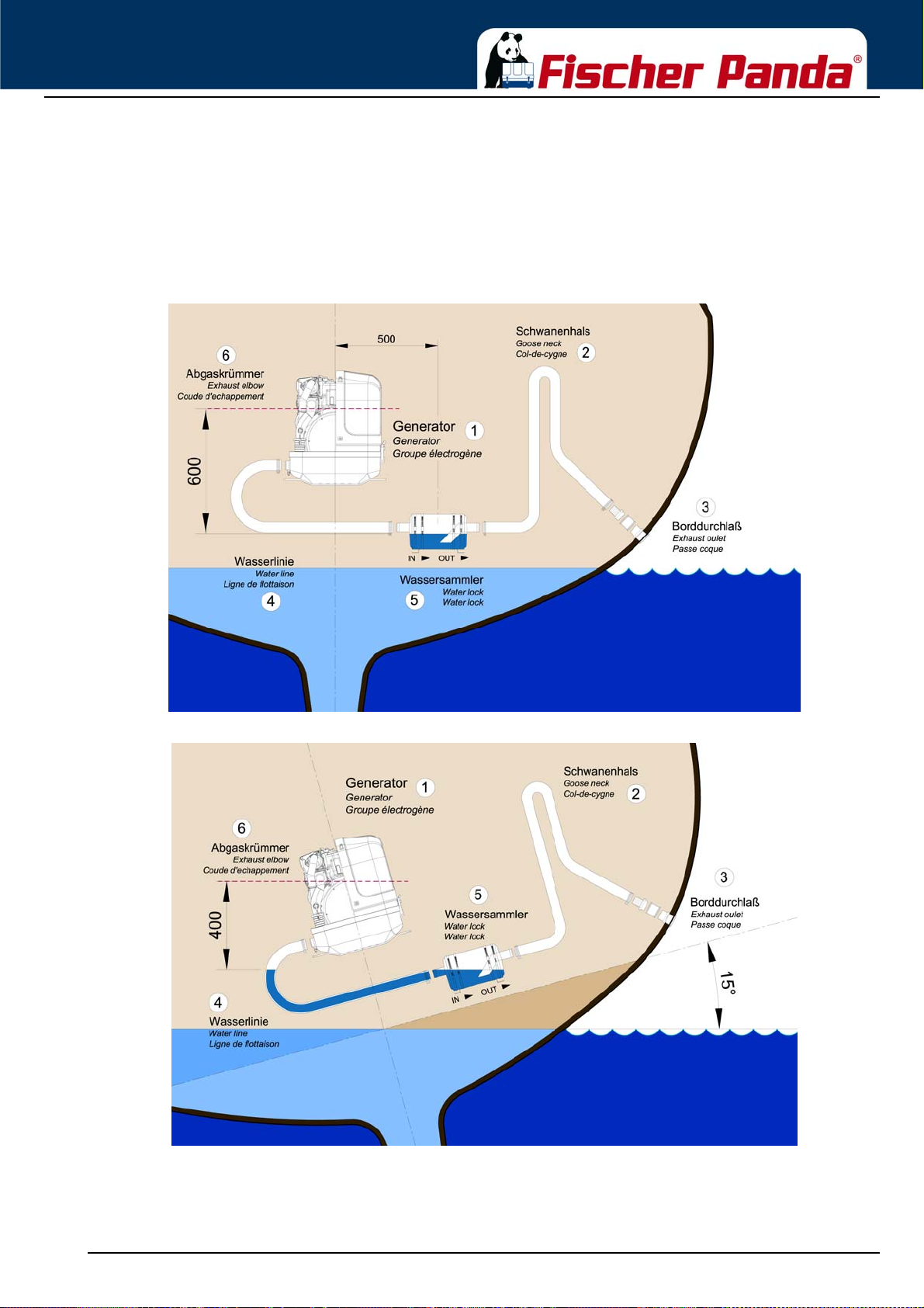
Installation Instructions
6.11.3.2 Example of the installation of the waterlock off-center and possible effects:
The following pictures are primarily relevant for an installation of the generator with the waterlock on sailing yachts.
A change in the mounting position caused by tilted position does not have to be reckoned concerning motor yachts.
Here it is only necessary to regard that the volume of the waterlock is measured so large that it can take the entire
amount of water flowing back, and at the same time, maintains the minimum distance of 600 mm.
A) Installation of the waterlock 500 mm next to the generator’s center line:
Fig. 6.11.3.2-1: waterlock, 500 mm next to the center line
Fig. 6.11.3.2-2: Tilted position, 15 degrees
Tilted position 15 degrees - Fig. 6.11.3.2-2
The distance is only 404 mm instead of the original 600 mm. So this is very close to the critical point.
18.12.15 Kapitel/Chapter 6: Installation Instructions - Seite/Page 91
Page 92
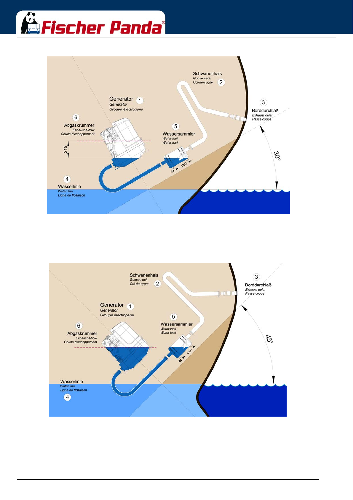
Fig. 6.11.3.2-3: Tilted position 30 degrees
Installation Instructions
Tilted position 30 degrees - Fig. 6.11.3.2-3
The distance between the hydrostatic head and the critical point at the exhaust elbow is only 216 mm. This means
that in a tilted position of 30 degrees you already face the highest risk of sea water sloshing into the combustion
chamber.
Fig. 6.11.3.2-4: Tilted position 45 degrees
Tilted position 45 degrees - Fig. 6.11.3.2-4
The water level is now at the same height as the critical point at the exhaust elbow. If the ship is sailed in a tilted
position of 45 degrees with an installation like this, the ingress of cooling water into the combustion chamber is
inevitable. Irreparable damages are pre-programmed.
Seite/Page 92 - Kaptitel/Chapter 6: Installation Instructions 18.12.15
Page 93
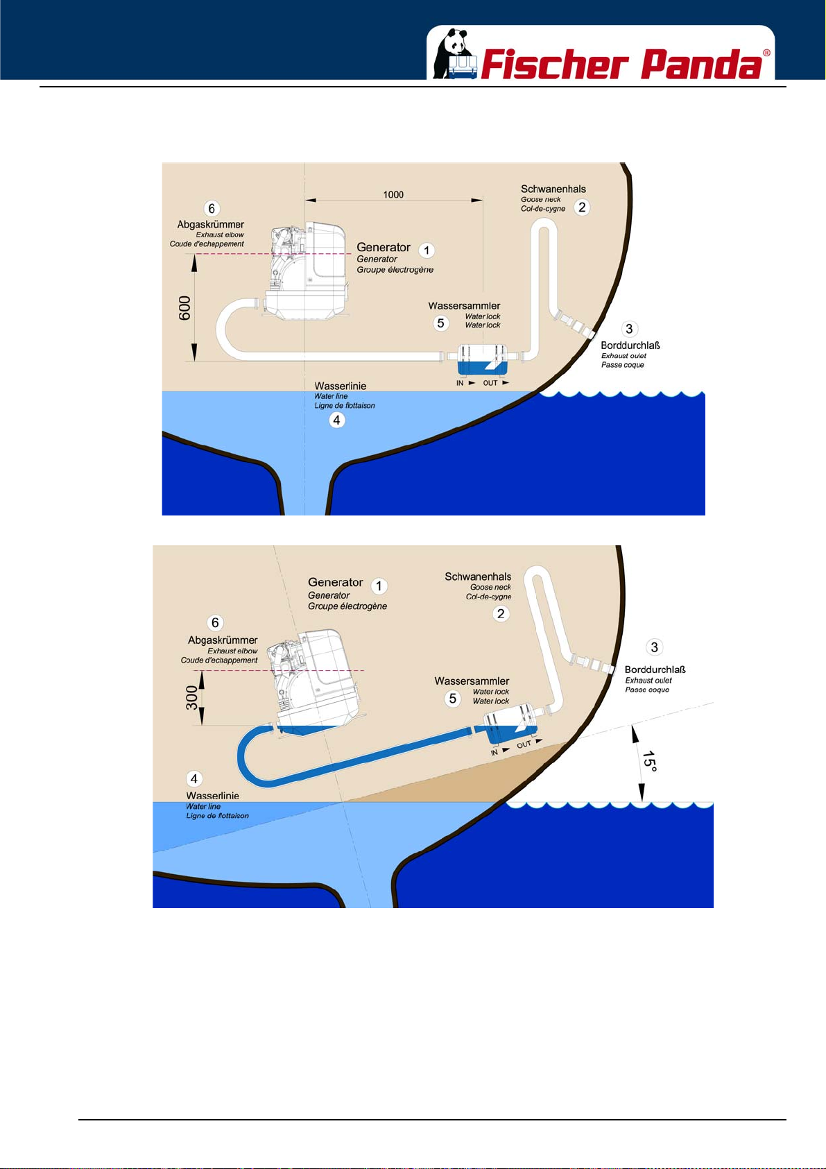
Installation Instructions
B) Installation distance between waterlock and the generator’s center line 1000 mm
Fig. 6.11.3.2-5: waterlock, 1000mm next to center line
Fig. 6.11.3.2-6: Tilted position 15 degrees
Tilted position 15 degrees - Fig. 6.11.3.2-6
The distance is, contrary to the original 600 mm, only 327 mm. This is very close to the critical point already.
18.12.15 Kapitel/Chapter 6: Installation Instructions - Seite/Page 93
Page 94
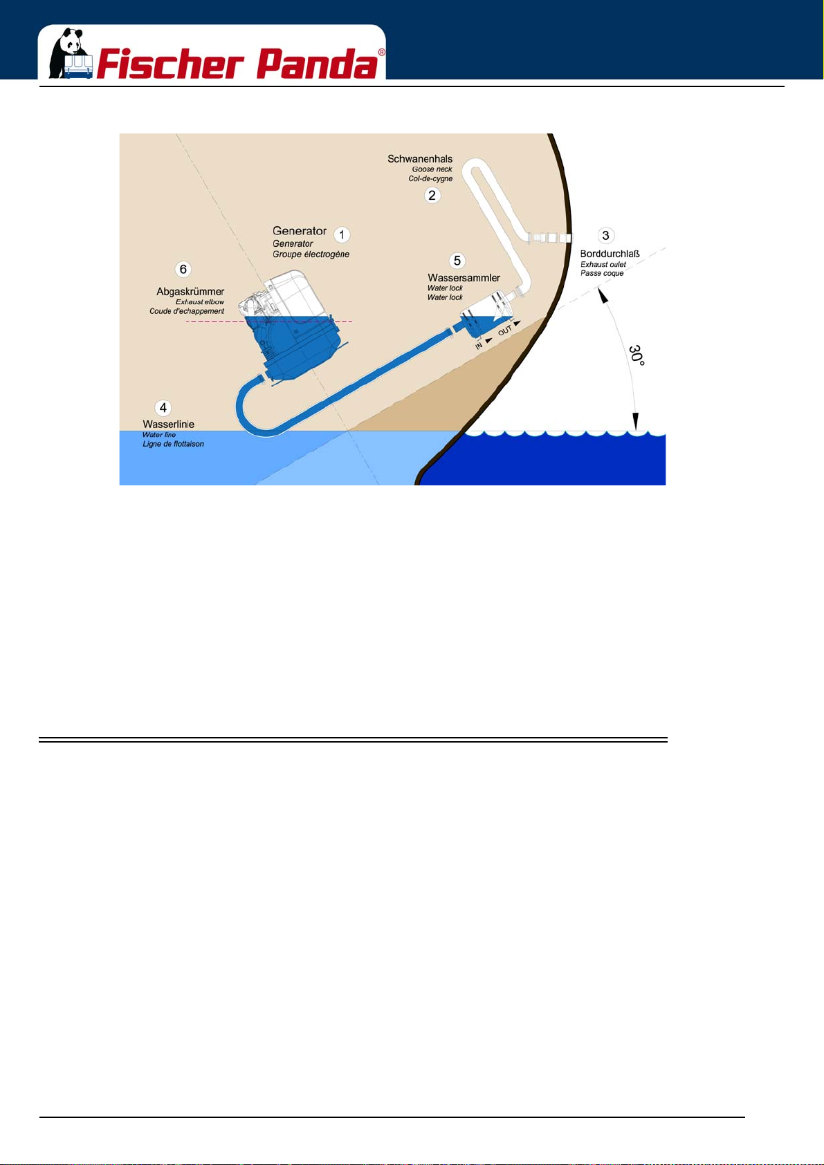
Fig. 6.11.3.2-7: Tilted position 30 degrees
Installation Instructions
Tilted position 30 degrees - Fig. 6.11.3.2-7
The water level and the critical point at the exhaust elbow are at the same level now. If th e ship is sailed in a tilted
position of 30 degrees with an installation like that, the infiltration of cooling water into the combustion chamber is
inevitable. Irreparable damages are pre-programmed.
Summary:
Concerning sailing yachts it must be regarded, that the waterlock is mounted in center underneath the generator, at
least in reference to the ships’ center line. Thus the waterlock is prevented from „leaking“ very strongly when the
ship is tilted.
The „leaking“ of the waterlock leads to a rise of the water level which then gets too close to the exhaust elbow’s
critical point.
6.12 Exhaust / water separator
In order to reduce the noise level of the gener ator unit to a minimum, an optional exhaust outlet muffler can be
mounted next to the through-hull fitting. Additionally there is a component at Fischer Panda, which acts as both an
„exhaust goose neck“, and water separator. With this „exhaust/water separator“ the cooling water is derived over a
separate pipe. The exhaust noises emana ting from the exter ior of the yacht are strongly decreased. Particularly the
„water splash“.
Seite/Page 94 - Kaptitel/Chapter 6: Installation Instructions 18.12.15
Page 95
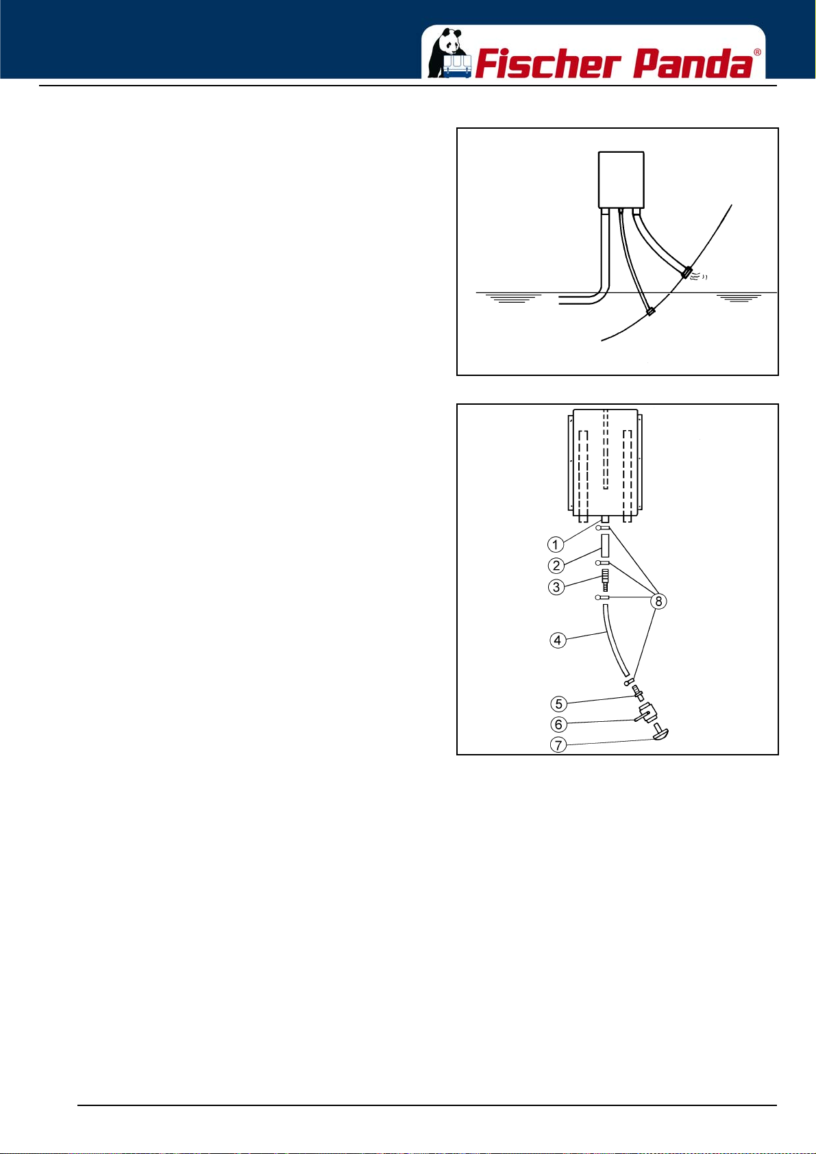
Installation Instructions
(1) Raw water outlet
Fig. 6.12.0-1: Water Flow Exhaust Water SeparatorWater flow exhaust water Separator
Fig. 6.12.0-2: Exhaust Water SeparatorWater flow exhaust water Separator
(2) Hose connector
(3) Reducer (if required)
(4) Hose
(5) Hose connector
(6) Sea cock
(7) Hull outlet
(8) Hose Clips
18.12.15 Kapitel/Chapter 6: Installation Instructions - Seite/Page 95
Page 96
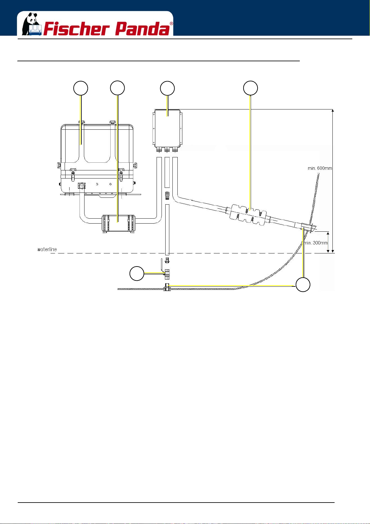
6.12.1 Installation exhaust water separator
1
5
6
2
3
4
1. Generator
2. Silencer / Water lock
3. Exhaust-Water-Separator
4. Silencer
5. Sea cock
6. Hull outlet
Fig. 6.12.1-1: Installation Exhaust Water Separator
Installation Instructions
If the exhaust water separator was sufficiently highly ins talled, a goose neck is no longer necess ary. The exhaust/
water separator fulfils the same function. If the „Super silent“ exhaust system were installed correctly, the generator
will not disturb your boat neighbour. The exhaust noise should be nearly inaudible. The best result is reached, if the
hose line, which derive the cooling water, is relocate on a short way „falling“ directly to the outlet and this outlet is
under the waterline.
If the through-hull exhaust outlet has to be mounted far from the generator, an exhaust-water separator must
definitely be installed. The raw water from the separator must then run along the shortest possible path in the
through-hull outlet. For such long exhaust routes, the exhaust hose diameter should also be increased, f.e. from
NW40mm to NW50mm in order to reduce the back-pressure. The exhaust may have a length of over 10m (32 ft.) if
the exhaust hose diameter is increased. An additional outlet exhaust muffler close to the hull outlet will help further
to reduce noise emissions.
The generator will not disturb your boat neighbours, if the „Super silent Exhaust System has been correctly installed.
The exhaust noise should be almost inaudi ble .
Seite/Page 96 - Kaptitel/Chapter 6: Installation Instructions 18.12.15
Page 97
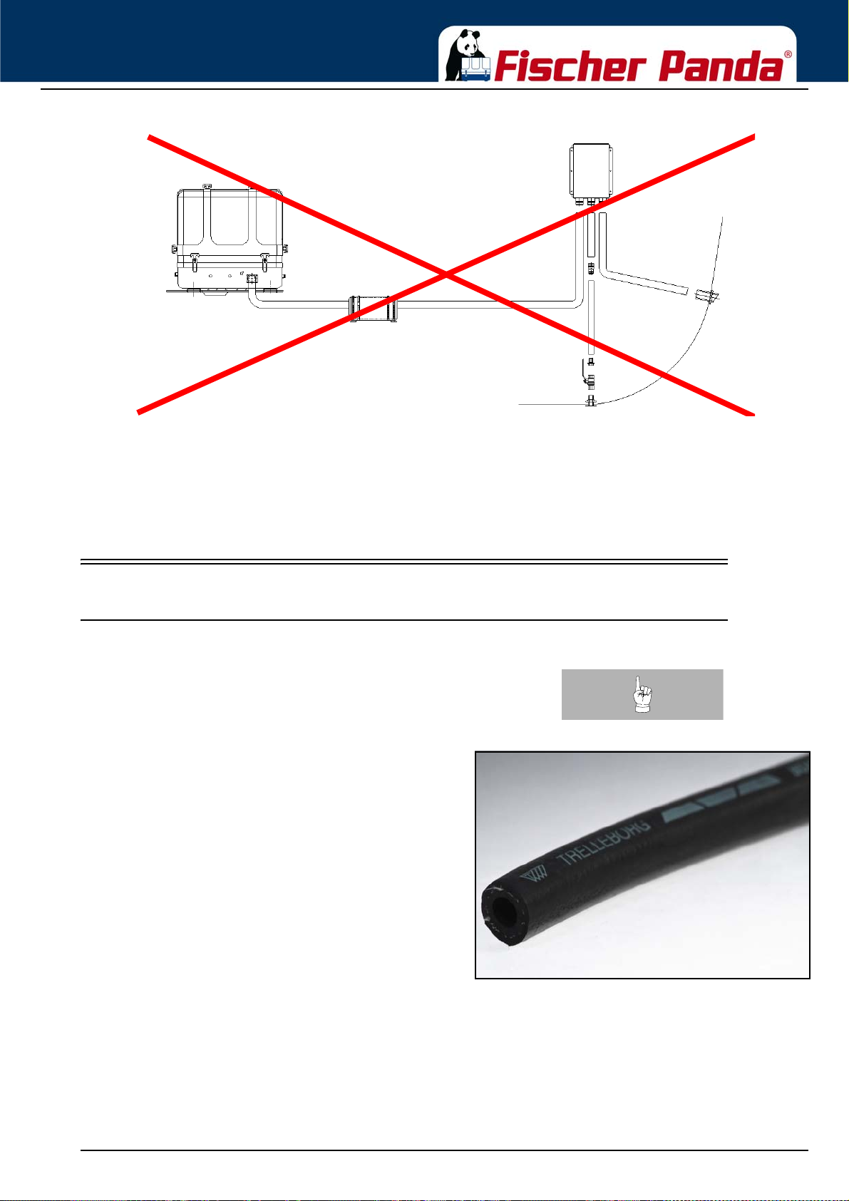
Installation Instructions
Example of an unfavourable installation:
- Water lock not far enough below the lowest level of the generator
- Distance water lock to exhaust/water separator too large
Fig. 6.12.1-2: Example for an unfavourable Installation
6.13 Fuel system installation
6.13.1 Fischer Panda installation kit - Fuel system
the specified installation. You can purchase them as an
installation kit or separately at Fischer Panda.
representative picture
Note:The following additional components will be required for
Fig. 6.13.1-1: Fuel hoseFuel hose
18.12.15 Kapitel/Chapter 6: Installation Instructions - Seite/Page 97
Page 98
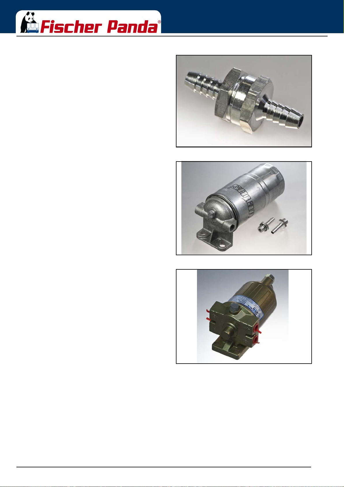
representative picture
representative picture
Installation Instructions
Fig. 6.13.1-2: No return valveNo return valve
Fig. 6.13.1-3: Pre filter with water separatorPre filter with water separator
Alternative Article
representative picture
Fig. 6.13.1-4: Pre filter with water separatorPre filter with water separator
Seite/Page 98 - Kaptitel/Chapter 6: Installation Instructions 18.12.15
Page 99
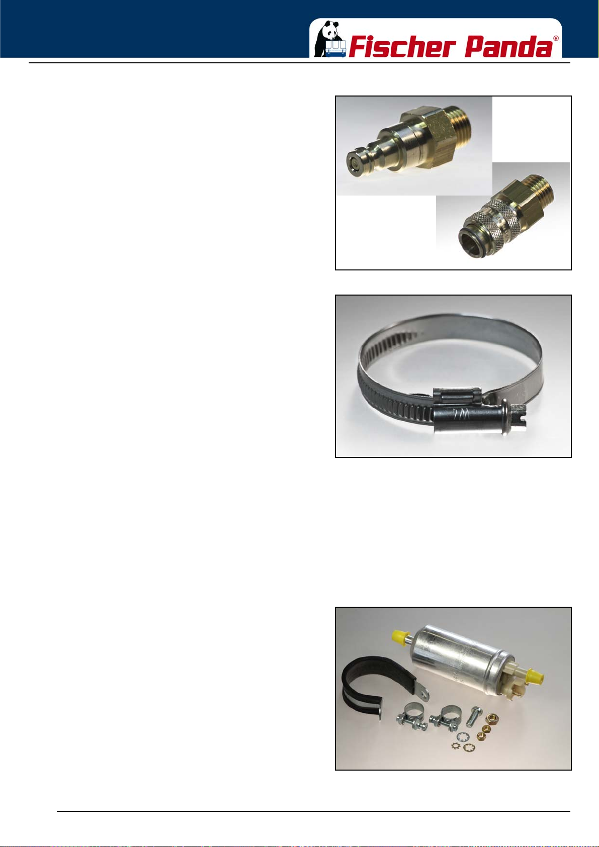
Installation Instructions
representative picture
representative picture
Fig. 6.13.1-5: Quick connector for fuel linesQuick connector for fuel lines
Fig. 6.13.1-6: Hose clampsHose clamps
6.13.1.1 The following items need to be installed:
• Fuel supply pump (DC)
• Pre-filter with water separator (not part of the delivery)
• Fine particle fuel filter
• Return fuel line to fuel tank (unpressurized)
The external Fuel pump should be installed near the tank
With the Fischer Panda generator is usually supplied an
external, electrical fuel pump (DC). The fuel pump must be
installed close at the fuel tank. The electrical connections is
prepared at the generator.
Some generators (f.e. with Deutz diesel engine) has an
engine driven internal fuel pump. At these generators the
electrical fuel pump is optional.
Fig. 6.13.1-1: electrical fuel pumpElectrical fuel pump
18.12.15 Kapitel/Chapter 6: Installation Instructions - Seite/Page 99
Page 100
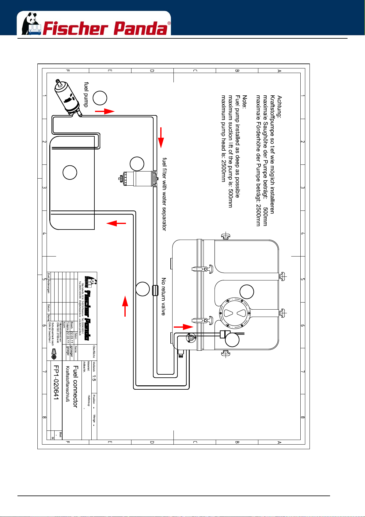
Installation Instructions
5
2
3
4
1
6
1. Fuel tank
2. external fuel pump
3. external fuel prefilter with water separator
4. Non return valve
5. Fuel fine filter
6. Generator
Fig. 6.13.1-2: Fuel system - schema
Seite/Page 100 - Kaptitel/Chapter 6: Installation Instructions 18.12.15
 Loading...