

Page 1
Connector : WSO 1031
with sealed or unsealed cable clamp
Fischer Connectors SA
Saint-Prex, Switzerland
Phone +41 21 800 95 95
Fax +41 21 800 39 24
www.fischerconnectors.com
mail@fischerconnectors.ch
Assembly Instruction
Instruction de Montage
Montageanleitung
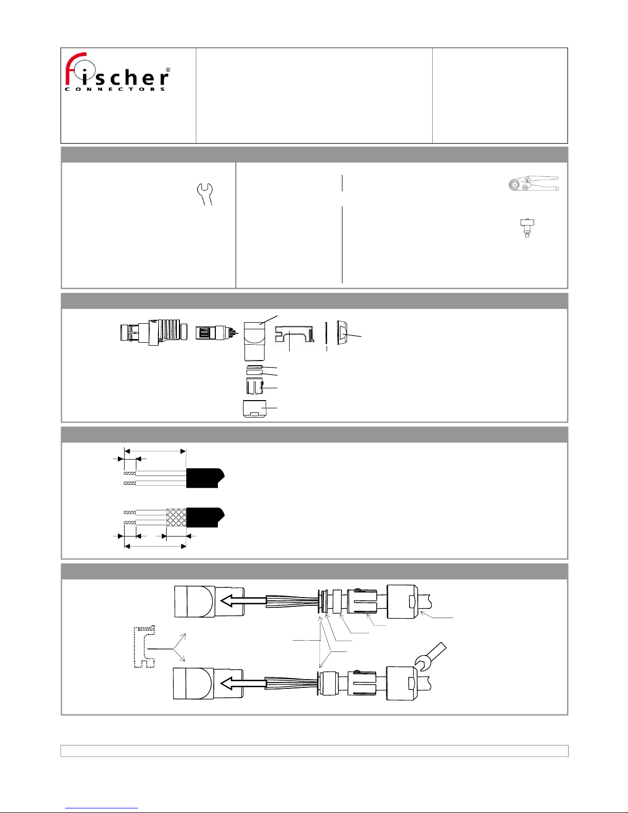
Tool Required
For all versions:
• Flat Spanners:
• 12 mm
• Wire Cutter
• Stripping Tool
• Soldering Iron
Fischer Part Number
TX00.012
Additional tools for Crimp Contact versions:
• Crimping Tool for:
• Positioner for:
Fischer Part Number
TX00.240
TX00.301
TX00.303
TX00.304
TX00.305
2 - Strip Cable
1 - Disassemble Connector
3 - Assemble Clamp Set
Document No. 600.00.439 Rev : 1.2 Date : 18-May-2015 Established by : ARZ/VGI Approved by : SKE
© Fischer Connectors SA / All rights reserved
This document is the property of Fischer Connectors SA.
All communications to third parties or the reproduction in any form, even partial, are prohibited without our written consent.
Connector
Body (a)
Contact
Block (b)
Right Angle Body (c)
Spacer (d) O-ring (e)
Back Nut (f)
Ring (g)
Cap Nut (j)
Cable Clamp (i)
Seal (h)
A
C
A
A ≈ 20-22 mm
(1)
B ≈ 2 mm
(1)
C ≈ (6 – 1/2 cable Ø) mm
(1) (2)
Or trim shield after step 3
if possible
B
(2)(1)
These values are given for reference and must
be adjusted to each specific cable
construction.
It is recommended to strip “B” after step 3.
Sealed Clamp Version
Unsealed Clamp Version
Jacket position for
non-shielded cables
Cable Shield
Ring (g)
Seal (h)
Cable Clamp (i)
Right Angle Body (c)
Recommended torque value: 1.5 Nm
(depending on cable)
Threadlocking adhesive recommended
(*) See note (2) in step 2
12
(*)
(*)
Cap Nut (j)
• 0.5 to 1.3mm contacts
• 0.5mm male contacts
• 0.5mm female contacts
• 0.7mm male contacts
• 0.7mm female contacts
See step 4:
with large
cables, insert
spacer before
Page 1/2
Page 2
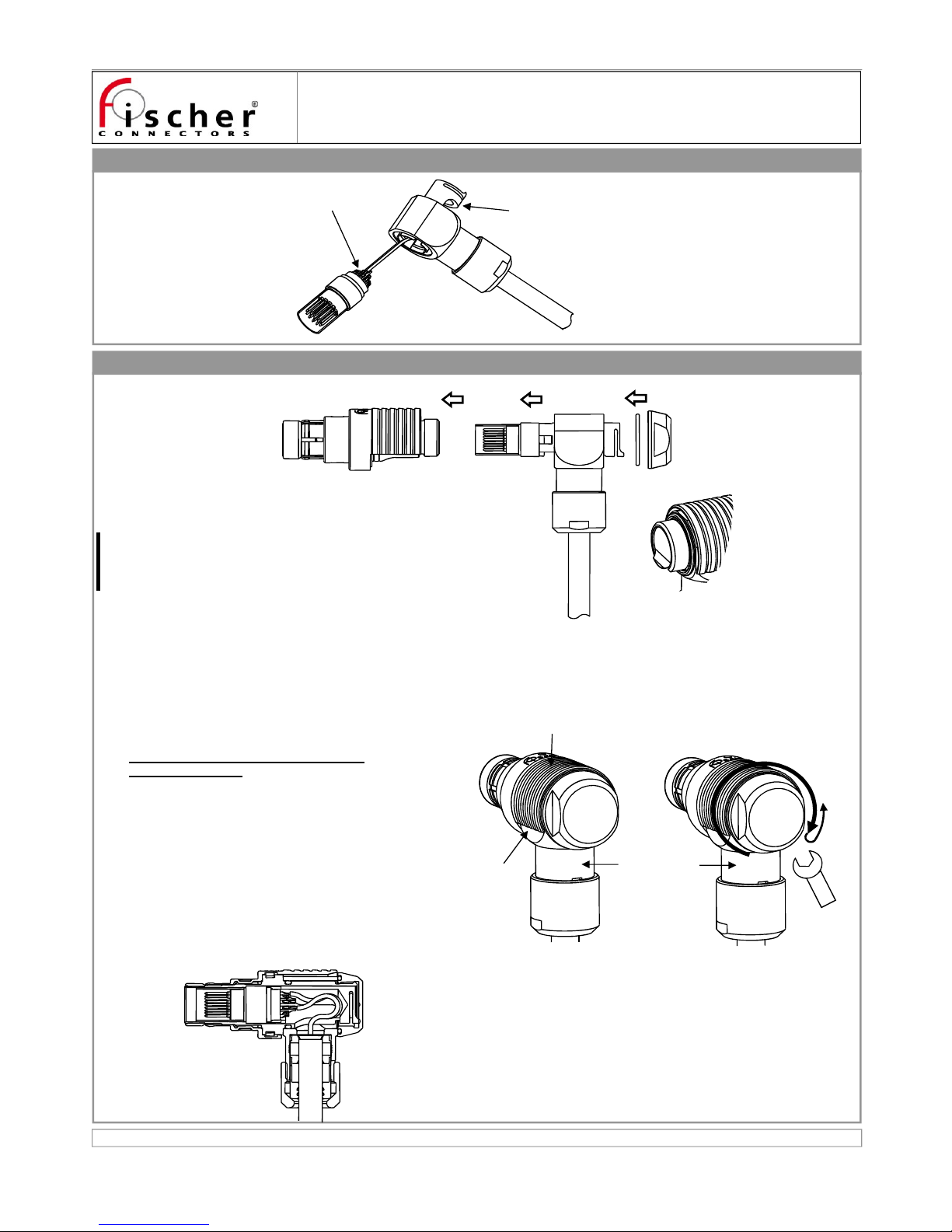
4 - Terminate Contacts
5 - Assemble Connector
Connector : WSO 1031
with sealed or unsealed cable clamp
Document No. 600.00.439 Rev : 1.2
Solder or crimp
Pull Spacer (d) over Cable and
through Right Angle Body (c)
Tighten Back Nut (f). Torque ≈ 2.0 Nm
Do not squeeze Connector Body in a vice
to tighten Back Nut!
Confirm that Outer Sleeve of Connector Body (a) can move
freely. If not, it can be released by holding Right Angle Body (c)
and turning slightly Back Nut (f) counter-clockwise.
After the threadlocking adhesive has cured, check locking
mechanism by mating connector with counterpart and
pulling on Right Angle Body (c) in unmating direction. The
connector should stay mated.
Pull on Outer Sleeve of connector. It should unlock and
disconnect.
5B
Correct fit of
Spacer (d)
Fit Spacer (d) onto Contact Block (b), bending wires smoothly and being careful
not to damage wires.
Caution with crimp contacts:
Crimp contacts need extra space in the insulator, therefore they can move.
Never twist the cable and wires during the cable assembly; this can apply
too much force on the contacts.
Insert Block (b) into Connector Body (a).
Apply threadlocking adhesive on inner thread of Back Nut (f).
Fit O-ring (e) into Back Nut (f) and close connector.
5A5B
5C
Outer Sleeve of
Connector Body
Gap on
both sides
Ensure that Right Angle Body (c) is centred in Outer Sleeve of
Connector Body (a) (gap on both sides) before tightening Back
Nut (f).
5D
Right Angle
Body (c)
5E
5F
12
5A
5B
5C
5D
5E
5F
5G
Page 2/2
 Loading...