

Page 1
Operating manual
MS13
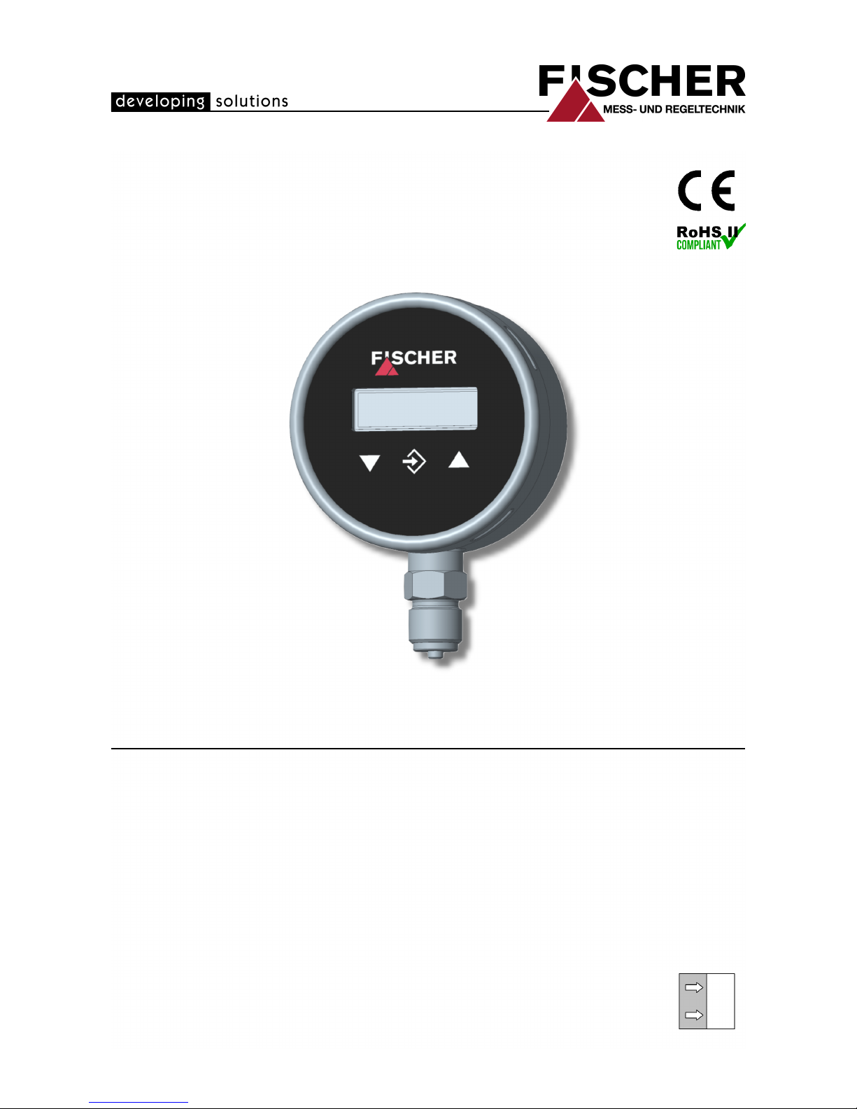
Digital pressure transmitter / switch
with colour change display
09005885 • BA_EN_MS13 • Rev. ST4-A • 10/16
*09005885*
Page 2

| Masthead FISCHER Mess- und Regltechnik GmbH
2 / 32 BA_EN_MS13
Masthead
Manufacturer:
FISCHER Mess- und Regeltechnik GmbH
Bielefelderstr. 37a
D-32107 Bad Salzuflen
Telefon: +49 5222 974 0
Telefax: +49 5222 7170
eMail: info@fischermesstechnik.de
web: www.fischermesstechnik.de
Technical editorial team:
Documentation representative: S. Richter
Technical editor: R.Kleemann
All rights, also those to the translation, reserved. No part of these instructions
may be reproduced or processed, duplicated or distributed using electronic systems or any other form (print, photocopy, microfilm or another process) without
the written consent of the company Fischer Mess- und Regeltechnik GmbH,
Bad Salzuflen.
Reproduction for internal use is expressly allowed.
Brand names and procedures are used for information purposes only and do
not take the respective patent situation into account. Great care was taken
when compiling the texts and illustrations; nevertheless, errors cannot be ruled
out. The company FISCHER Mess- und Regeltechnik GmbH will not accept any
legal responsibility or liability for this.
Subject to technical amendments.
© FISCHER Mess- und Regeltechnik 2016
Version history
Rev. ST4-A 04/16 Version 1 (first edition)
Page 3

FISCHER Mess- und Regltechnik GmbH Table of Contents
BA_EN_MS13 3 / 32
Table of Contents
1 Product and functional description ..............................................................................................................4
1.1 Delivery scope ..........................................................................................................................................4
1.2 Performance features ...............................................................................................................................4
1.3 Intended use .............................................................................................................................................4
1.4 Product Overview .....................................................................................................................................5
1.5 Function diagram ......................................................................................................................................6
1.6 Design and mode of operation..................................................................................................................7
2 Installation and assembly..............................................................................................................................8
2.1 Generalities...............................................................................................................................................8
2.2 Process connection ..................................................................................................................................8
2.2.1 Measuring lines that need to be connected ..................................................................................9
2.2.2 Pressure surge absorption............................................................................................................9
2.3 Electrical connections .............................................................................................................................11
3 Commissioning.............................................................................................................................................12
3.1 General ...................................................................................................................................................12
3.2 Control elements.....................................................................................................................................12
3.2.1 LC display ...................................................................................................................................12
3.2.2 Keyboard..................................................................................................................................... 13
3.3 Menu levels.............................................................................................................................................14
3.3.1 Menu Level Switch points ...........................................................................................................14
3.3.2 Menu Level Input ........................................................................................................................15
3.3.3 Menu Level Measuring................................................................................................................ 16
3.3.4 Menu Level Output...................................................................................................................... 17
3.3.5 Menu Level Function................................................................................................................... 18
3.3.6 Menu Level Display..................................................................................................................... 20
3.3.7 Menu Level System .................................................................................................................... 22
4 Technical Data .............................................................................................................................................. 24
4.1 General Information ................................................................................................................................24
4.2 Input variables ........................................................................................................................................24
4.3 Output parameters..................................................................................................................................24
4.4 Measurement accuracy ..........................................................................................................................25
4.5 Auxiliary energy .....................................................................................................................................25
4.6 Application conditions .............................................................................................................................25
4.7 Display and operating interface ..............................................................................................................26
4.8 Construction design ................................................................................................................................26
4.8.1 Dimensional picture .................................................................................................................... 26
4.8.2 Process connection..................................................................................................................... 27
5 Order Codes..................................................................................................................................................28
5.1 Accessories ............................................................................................................................................29
6 Attachments..................................................................................................................................................30
Page 4

1 | Product and functional description FISCHER Mess- und Regltechnik GmbH
4 / 32 BA_EN_MS13
1 Product and functional description
1.1 Delivery scope
• MS13 Digital pressure transmitter / switch
• Operating instructions
The unit is supplied ex-works with standard parameters.
For accessories, please see the list in section Order code [}29].
1.2 Performance features
Important features
• LCD colour change display
• Switchable pressure units
• 2 independent switching points with lots of configuration options
• Analogue signal output with possibility of characteristic curve spread, characteristic curve reversal and offset setting
• Characteristic curve implementation via table with max. 30 measuring points
• Complete adjustment of all parameters and measuring point protocol possible through optional transmitter PC interface.
Typical applications
• Simple pump control systems
• Monitoring of pumps and compressors
• Filling level measuring
Application areas
• Technical facility equipment (TGA)
• Process engineering
• Process technology
• Environmental technology
1.3 Intended use
The MS13 is a pressure transmitter/ switch for measuring relative pressure. The
unit is suitable for measuring pressure and under-pressure in non-agressive
gas-like and fluid media.
The MS13 complies with the state-of-the-art and is safe; it also takes into account the relevant regulations and EC directives. The manufacturer will not be
liable for damage arising from incorrect or improper use.
The unit was designed bearing in mind all relevant factors that could impact on
its safety. Also, the unit was produced, inspected and supplied with a user
manual so that if it is used in unforeseeable reasonable conditions, its safety is
guaranteed for its entire service life.
NOTICE
Soiled or aggressive media
Please contact the manufacturer before using this unit with dirty or aggressive
media because the unit needs to be adapted for the specific customer in terms
of the parts that come into contact with the media.
The device may only be used for the purpose stipulated by the manufacturer.
Page 5
FISCHER Mess- und Regltechnik GmbH Product and functional description | 1
BA_EN_MS13 5 / 32
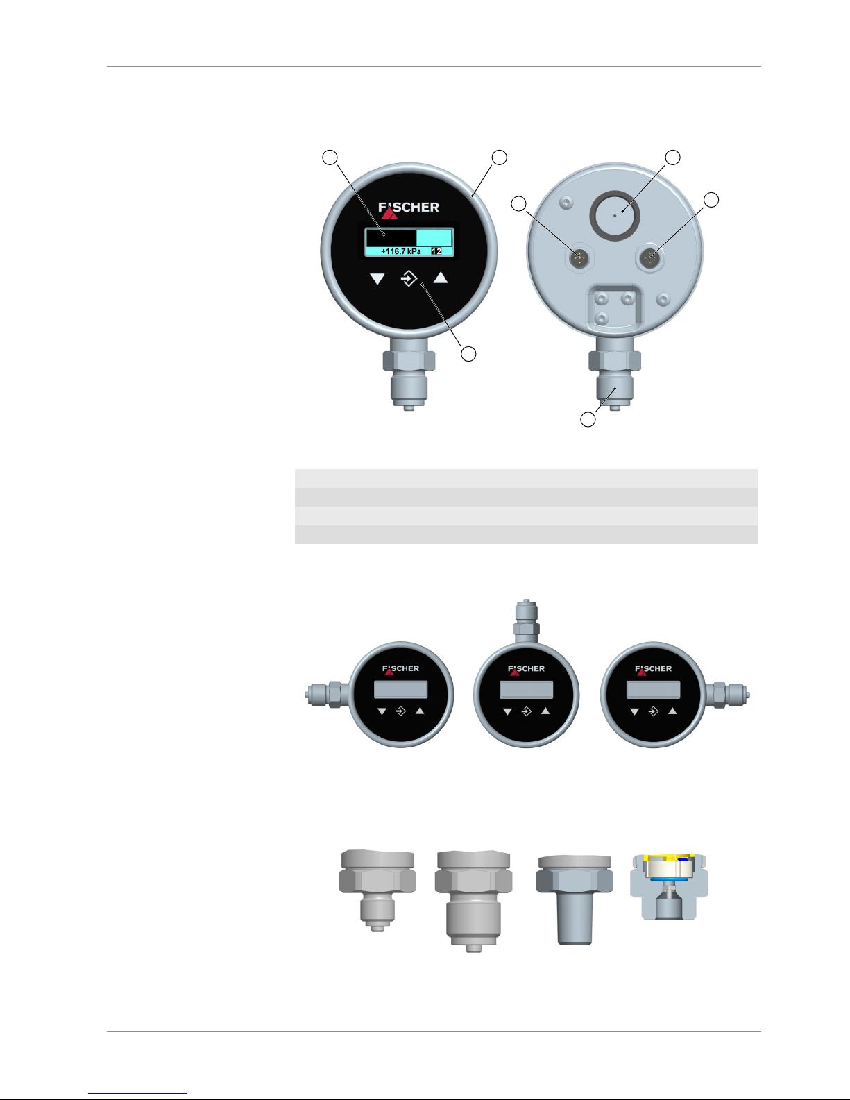
1.4 Product Overview
All units of the series MS13 are supplied in an NG100 bayonet ring housing
made of stainless steel.
1 2
3
4
5
6
7
Code U
Process connection
Illustration1: Product Overview
1 Colour change display 2 Bayonet ring housing
3 Keyboard 4 Process connection
5 Blowout plug 6 M12 plug 1
7 M12 plug 2
Process connection
The following options are available for the process connection.
Code L
Process connection
0 R
Illustration2: Process connection direction
Code 85 87 88 S1
G½ B ¼ -18 NPT EXTG¼ B Schrader ®
Illustration3: Process connections
Page 6
1 | Product and functional description FISCHER Mess- und Regltechnik GmbH
6 / 32 BA_EN_MS13
Code Process connection
85 Connection shanks with external thread G¼ B
87 Connection shanks with external thread G½ B
88 Connecting port with outer thread ¼ -18 NPT EXT
S1 Schrader® screw connection inner thread 7/16 UNF
Electrical connections
The power is connected using two M12 connectors.
M12 flanged connector DIN EN 61076-2-101 coding A
Connector 1 5-pin Ms-nickel-plated
Connector 2 4-pin Ms-nickel-plated
Nameplate
This type plate serves as an example of the information that is stated. The data
shown is purely fictive, but does correspond to the actual conditions. For more
information, please see the order code at the end of these instructions.
MESS- UND
REGELTECHNIK
GmbH
D-32107 Bad Salzuflen
Article no MS1303M87PKC0MV0
Measuring range 0-1.6 bar
electrical output 4 - 20 mA / 3-wire
Oper. voltage 24V AC/DC
P max. 3.2 Bar (45 PSI)
Prod. No. 1600624.01.001
Made in Germany
142
3
142
3
*
ge/gnswbr
wsblsw
br
ws
bl
+ Signal
+ supply
- Signal
- supply
( GND)
Plug guide
Switch
contact 1
Switch
contact 2
* bridged
internally
Order Codes
Serial number
Wiring diagrams
Technical data
Illustration4: Nameplate
1.5 Function diagram
SP2
1.275 bar
U/I
SP1
D
A
A
D
µC
IJK
3
4 5
6
7
2
1
Illustration5: Function diagram
Page 7

FISCHER Mess- und Regltechnik GmbH Product and functional description | 1
BA_EN_MS13 7 / 32
1 Measuring cell 2 A/D converter
3 Micro-controller 4 Keyboard
5 Switching outputs 6 LCD colour change display
7 D/A converter
1.6 Design and mode of operation
The device is based on a ceramic sensor element that is suitable for measuring
over-pressure and under-pressure. The pressure deforms the measuring membrane causing a change in resistance on the attached measuring bridge. This
change is evaluated by the device's electronics and transformed into the display, switch contacts or an standardised analogue output signal.
The optional output signal can be dampened, spread, inverted and transformed
via a table function even if it is non-linear. Overstepped limits can be visualised
with the LCD colour change display.
The unit is configured with a keyboard or by means of remote configuration from
a PC.
Page 8
2 | Installation and assembly FISCHER Mess- und Regltechnik GmbH
8 / 32 BA_EN_MS13
2 Installation and assembly
2.1 Generalities
The instrument may only be installed and commissioned by specialized personnel familiar with the installation, commissioning and operation of this product.
Specialized personnel are persons who can assess the work they have been
assigned and recognize potential dangers by virtue of their specialized training,
their skills and experience and their knowledge of the pertinent standards.
WARNING
Mounting pressure transmitters
During assembly, observe the respective national and international guidelines
and safety regulations.
Only mount the pressure transmitter to systems that are depressurized. Only
ever operate the unit within the permitted measuring range or below the maximum overload.
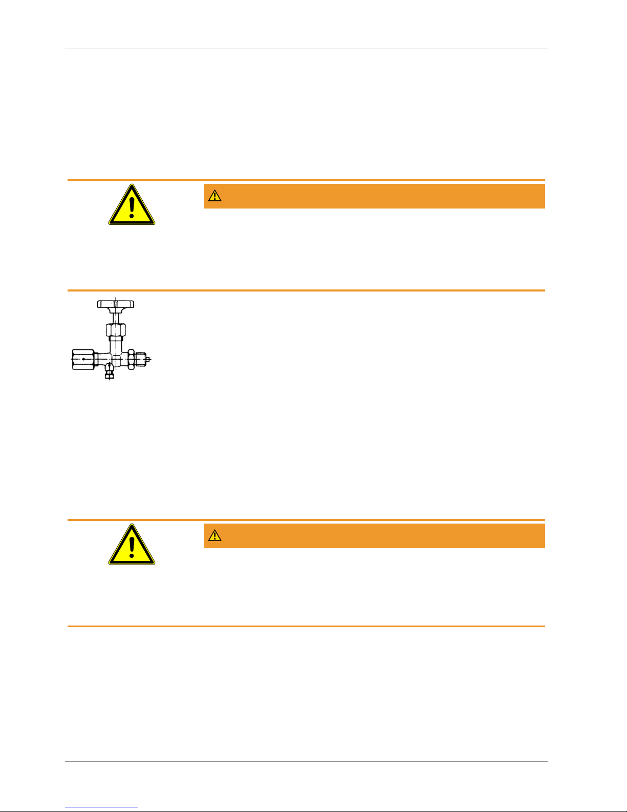
Illustration6: Shutoff valve.
The device is set ex-works for vertical installation, however any installation position is possible.
To guarantee safe working conditions during installation and maintenance, suitable stop valves must be fitted in the system (see accessories). By means of
the manometer shutoff, the unit
• Can be depressurized or taken out of operation.
• Be disconnected from the power supply within the applicable system for repairs or inspections.
2.2 Process connection
• By authorized and qualified specialized personnel only.
• The pipes need to be depressurized when the instrument is being connected.
• Appropriate steps must be taken to protect the device from pressure surges.
• Check that the device is suitable for the medium being measured.
• Maximum pressures must be observed (cf. Tech. data)
WARNING
Earth connection via the system earth
During assembly, ensure that the earth connection between the pressure transmitter and the system earth is ensured. The connection to the system earth is
realised via the process connection. Therefore, never use an insulated Teflon
tape or similar. Design the process connection acc. to EN 837 and use a suitable flat seal.
Page 9
FISCHER Mess- und Regltechnik GmbH Installation and assembly | 2
BA_EN_MS13 9 / 32
2.2.1 Measuring lines that need to be connected
The following points need to be observed when connecting the pressure line:
• To ensure there is no influence on the measured values, severe bends and
coils in the wire should be avoided.
• To prevent deposits, there should be a continuous incline or drop of at least
8%.
• When measuring steam pressure, a water bag-forming loop must be
provided due to the temperature (see accessories).
Round shape U-shape
G½
ca. 180
Ø20
56
155
ca. 200
G½
G½
ca. 275
ca. 130
Ø20
Ø56
G½
SW27
Manometer connection
Connection spigot
according to DIN EN 837-1
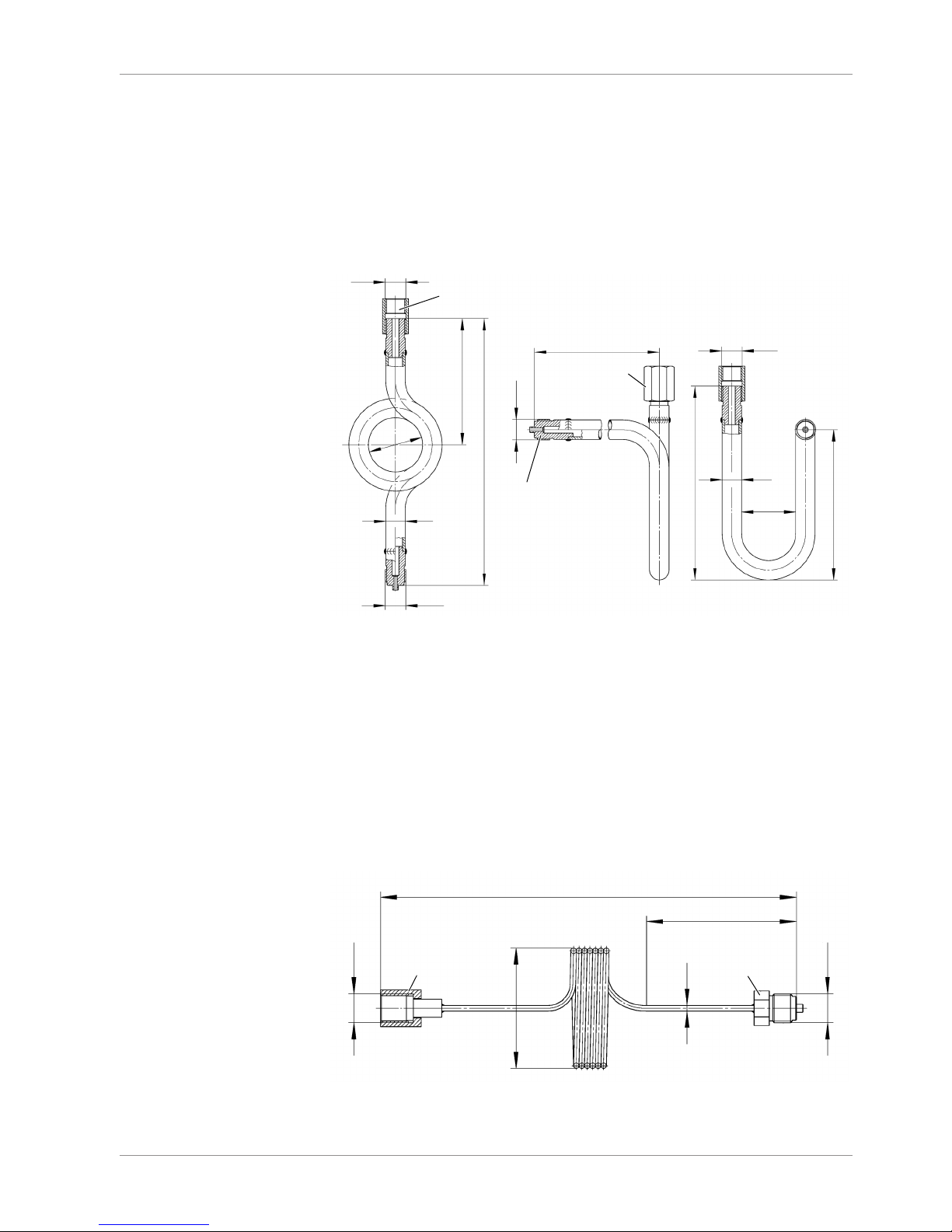
Illustration7: Siphon MZ1###
• The transmitter must be positioned below the measuring point for liquid
measurements. Vent the pressure line before commissioning.
• The transmitter must be positioned above the measuring point for gas
measurements.
2.2.2 Pressure surge absorption
Pulsating pressure on the system side can lead to functional problems. We recommend installing a damping element in the pressure connection lines as a
protective measure.
a) Capillary throttle
Manometer connection
SW27 SW27
Connection spigot
according to DIN EN 837-1
305
110
G½
G½
Ø88
Ø4
Illustration8: Capillary throttle MZ400#
Page 10

2 | Installation and assembly FISCHER Mess- und Regltechnik GmbH
10 / 32 BA_EN_MS13
b) Settable damping reactor
In operating mode, the damping throttle must be set so that the output signal
follows the pressure changes with a delay.
G½
G½
20
66
19
SW27
Setting screw
Connection spigot
according to DIN EN 837-1
Manometer connection
Illustration9: Damping reactor MZ410#
Page 11

FISCHER Mess- und Regltechnik GmbH Installation and assembly | 2
BA_EN_MS13 11 / 32
2.3 Electrical connections
• By authorized and qualified specialized personnel only.
• When connecting the unit, the national and international electro-technical
regulations must be observed.
• Disconnect the system from the mains, before electrically connecting the
device.
• Install the consumer-adapted fuses.
• Do not connect the connector if strained.
3-Leiterschaltung
Input
Output
AC
DC
Sensor
Signal
+U
b
- U
b
- Sig
+Sig
+U
b
- U
b
p
1
3
2
4
Connector 1: Supply and output signal
Illustration10: M12 connector 5pin
Item Description Cable colour
A Coding A
B Internal bridge
1 +U
b
Supply brown
2 -Sig Signal white
3 -U
b
Supply blue
4 +Sig Signal black
5 FE Functional earth Green/yellow
Connector 2: Switching outputs
Illustration11: M12 Plug 4-pin
Pos Description Cable colour
A Coding A
1 SP1 Switch point 1 (no) brown
2 SP2 Switch point 2 (no) white
3 SP2 Switch point 2 (com) blue
4 SP1 Switch point 1 (com) black
Page 12

3 | Commissioning FISCHER Mess- und Regltechnik GmbH
12 / 32 BA_EN_MS13
3 Commissioning
3.1 General
All electrical supply, operating and measuring lines, and the pressure connections must have been correctly installed before commissioning. All supply lines
are arranged so that there are no mechanical forces acting on the device.
Check that the pressure connections do not leak before commissioning.
3.2 Control elements
3.2.1 LC display
1
3
4
2
Illustration12: LC display
1 Measurement display 4…6 digits 2 Bar chart display
3 Status display of the switch
points
4 Unit
Illustration13: LC display 2SP
The unit is shown to the right of the measured value. If the device is equipped
with contacts, a closed contact is always symbolised by an inverted text "SP1"
or "SP2". One exception is the 1-channel bar chart diagram. Here, the switching
points are symbolised with simple numbers "12".
Page 13

FISCHER Mess- und Regltechnik GmbH Commissioning | 3
BA_EN_MS13 13 / 32
3.2.2 Keyboard
1
2
3
Illustration14: Keyboard
1 Page down menu Decrease value
2 Call up menu Save value OK
3 Page up menu Increase value
The individual menu items and parameters can be displayed using the buttons
and
. The respective menu item is selected or the parameters for making
changes are called up via the button
.
If a parameter can be changed, the display flashes. The change is made via the
buttons
and
. The value is saved with the button
.
To leave a menu level or the entire menu, select the parameter "Quit" and
press
.
Example: Switch-on point set switchpoint 1
In normal mode, press the button
to enter the menu. The menu level Switch
points appears. Press the enter key
again to call up the display parameter.
The first parameter Switch point 1 on is displayed. To change this parameter,
press the button
again.
The device jumps to the input:
• The parameter is stated in the 1st line.
• The value that is to be changed is shown in the 2nd line, the display flashes.
• The input limits are displayed in the 3rd line (if there is one).
The required value is set with the buttons
and
and then confirmed with
.
Page 14

3 | Commissioning FISCHER Mess- und Regltechnik GmbH
14 / 32 BA_EN_MS13
3.3 Menu levels
The menu levels are structured as follows:
End
menu level
Menu Level
Switch points
Menu Level
Input
Menu Level
Measuring
Menu Level
Output
Menu Level
Function
Menu Level
Display
Menu Level
System
End
menu level
Reception
Output
Output
Illustration15: Menu levels
The following tables provide an overview of the parameters of the individual
menu levels. In the Menu Level Systemyou can change to the respective national language using the language parameter. You can see which languages
are supported there.
3.3.1 Menu Level Switch points
Parameter name Description Value range
SP1 On Switch point 1 On MBA-50% … MBE+50%
SP1 Off Switching point 1 off MBA-50% … MBE+50%
SP1 delay Switching point 1 delay 0…1800 s
SP1 Function Switching point 1 function NO, NC
SP2 On Switch point 2 On MBA-50% … MBE+50%
SP2 Off Switching point 2 off MBA-50% … MBE+50%
SP2 delay Switching point 2 delay 0…1800 s
SP2 Function Switching point 2 function NO, NC
The two switching outputs are configured by four parameters respectively.
For the switch point 1 these are
Page 15

FISCHER Mess- und Regltechnik GmbH Commissioning | 3
BA_EN_MS13 15 / 32
• SP1 On
• SP1 Off
• SP1 delay
• SP1 Function
Accordingly for switch point 2:
• SP2 On
• SP2 Off
• SP2 delay
• SP2 Function
The function of the individual parameters is explained for both switch points using Switch point 1 as an example.
SP1 On defines the activation point, SP1 Off the deactivation point of switching
output 1. The values are shown in the valid unit and set accordingly. The values
are shown in the valid unit and set accordingly. Both parameters can be set independently over the entire value range.
The value range ranges from MBA – 50% to MBE + 50%. MBA stands for start
of measuring range and MBE for the end of the measuring range.
Example: Measuring range = 0 … 160 kPa
The value range for this measuring range is -80 kPa … +240 kPa.
Together, the two parameters SP1 On and SP1 Off determine the switch function of switching output 1:
• If SP1 On > SP1 Off, the output switches on, if the measured value exceeds SP1 On. It is only switched off again if the measured value SP1 Off is
undercut (hysteresis function).
• If SP1 On = SP1 Off, the output switches on if the measured value exceeds
SP1 On and off if the measured value undercuts the same value (SP1 Off).
• If SP1 On < SP1 Off, the output switches on, if the measured value lies
within these switch points: i.e:
SP1 On < Measured value < SP1 Off (window function).
SP1 Delay allows the reaction of the switch output to be delayed by between 0
and 1800 s. This parameter applies equally for switching on and off.
SP1 Function changes the function of the switching output 1. It is possible here
to define whether the contact should work as a open contact (NO) or a break
contact (NC).
3.3.2 Menu Level Input
Parameter name Description Value range
Absorption Attenuation, damping 0…100 s
Offset corr. Offset correction ⅓ basic measuring
range
Zero-pt. wind. Zero-point window ⅓ basic measuring
range
If there are unsteady pressure readings during operation, you can use the parameters Absorption and Zero-pt. wind. to stabilise the reading and the output
signal.
The parameter Absorption functions like a capillary throttle. However, it only
acts on the display, output signal and switch points (if these exist) but not on the
measuring cell itself.
You can set the response time to pressure jumps in the range 0.0 to 100 s.
Page 16

3 | Commissioning FISCHER Mess- und Regltechnik GmbH
16 / 32 BA_EN_MS13
NOTICE
Response time
At maximum damping it can take over 2 minutes until the pressure jump from
the nominal pressure 100% to 0% is also shown as zero in the display.
In many cases, unsteady readings are not a problem during normal operating
mode, but this is not true for the idle state, i.e. if a measured value of zero is expected. The parameter Zero-pt. wind. is designed to solve this. Its value
defines a range around zero at which the measured value is set to zero (see
fig.).
The display only stops showing zero when the pressure leaves the set window.
When twice the window value is reached, the measuring pressure and the display correspond again. This avoids jumps in the display.
Differential pressure
Display value
-x-2x x 2x
Zero-point window
Illustration16: Zero-point window
It makes sense to set the Offset (zero-point displacement) if, without differential
pressure (remove measuring line), the display shows a value that is not zero.
Before the offset correction, the zero-point window must be set to zero.
Select the Offset corr. parameter and correct the reading using the buttons
or
until zero is shown in the display.
When setting the offset, the current measured value is displayed. The zeropoint window is not active during the offset setting.
3.3.3 Menu Level Measuring
Parameter name Description Value range
MB start Measuring range start Basic measuring
range
MB end Measuring range end Basic measuring
range
Unit Measuring range unit bar, mbar, Pa, kPa,
MPa, psi, InWc,
mmWs, mmHg
Limit Measuring range limit yes, no
The transmitter output signal primarily depends on the sensed pressure. However, you have the option of adjusting the output signal to a large extent to suit
your requirements.
Page 17

FISCHER Mess- und Regltechnik GmbH Commissioning | 3
BA_EN_MS13 17 / 32
NOTICE
Adjustment of the output signal
The basic measuring range (indicated on the type label) and the type of output
signal (voltage / current) are not variable.
The parameters MB start and MB end initially define the two pressures
between which the output signal will change at all. Both values are adjustable
across the entire basic measuring range. The set values also refer to the pressure in the respective unit. However, the signal values (current / voltage) for
‘Start of measuring range’ and ‘End of measuring range’ are fixed.
If MB start is smaller than MB end, this is called an increasing characteristic
curve; the output signal increases as the pressure increases.
If MB end is smaller than MB start, this is a decreasing characteristic curve and
the output signal decreases as the pressure increases.
The difference between the values MB start and MB end must be at least 25 %
of the basic measuring range.
You can select a unit other than the unit of the basic measuring range with the
parameter Unit. The user should remember however that not every unit is suitable. The conversion is automatic.
The parameter Limit allows the display, output and switching points to be limited to the range between Start of measuring range and End of measuring
range. This makes sense when content is measured to avoid "negative contents". If Limit is set to "no", those measured values that are greater or smaller
than the end values are shown.
3.3.4 Menu Level Output
Parameter name Description Value range
min. output min. output
0.0 … 21.0 mA or
0.0 … 11.0 V
max. output max. output
Error signal Measuring range unit
The parameters min. output, max. output and error signal define the limits of
the output signal that may not be undercut or exceeded regardless of the pressure. The limit values take priority over the range defined by the MB start and
MB end parameters! These parameters primarily serve to prevent error mes-
sages in downstream systems caused by brief overstepping of measuring
ranges.
The parameter min. output is usually only used for devices with an output signal 4…20 mA because frequently values of below 3.8 mA are evaluated as error signals.
The max. output value can be used for the voltage and current to limit the maximum value.
The value defined via the parameter Error signal is issued if the device detects
an internal error and can no longer work correctly. It should be noted here that
not all potential errors and faults can be detected by the device itself.
Page 18

3 | Commissioning FISCHER Mess- und Regltechnik GmbH
18 / 32 BA_EN_MS13
3.3.5 Menu Level Function
The Function menu level is a variable menu whose appearance depends on the
value of the Function parameter. There are linear, square rooted and table functions
Linear function
The input signal is linear before being sent to the display and the output. The
range defined in the menu "Measuring" serves as the measuring range. If the
function LINEAR is active, the other menu items are cancelled.
Parameter name Description Value range
Function Function Value = linear
Square rooted function
Here, the input signal is square rooted before being sent to the display and the
output. This is necessary e.g. for flow measurements with differential pressure.
A free unit can be defined for the display. To do this, the start and end of the
display range and the number of decimal points are defined. It is also possible
to define the unit with 4 characters.
Parameter name Description Value range
Function Function Value = square
rooted
MB decimal pl. Measuring range
decimal places
1234, 123.4, 12.34,
1,234, 12345, 123456
MB start Measuring range start -9999 … +9999
MB end Measuring range end -9999 … +9999
MB unit Measuring range unit 4 characters
The following section contains descriptions of the parameters MB decimal pl.,
MB start, MB end and MB unit to describe the table function.
Tables function
This function allows free adjustment of the input variable to the display and output via a table with up to 30 support points. A value pair comprising a measured
value and display value is issued for every support point.
NOTICE
Change of parameter
When switching from TABLE to another function, the table is initialised again
and the existing values are lost.
Parameter name Description Value range
Function Function Value = Table
MB decimal pl. Measuring range
decimal places
1234, 123.4, 12.34,
1,234, 12345, 123456
MB start Measuring range start -9999 … +9999
MB end Measuring range end -9999 … +9999
MB unit Measuring range unit 4 characters
No. of pairs Number of pairs n = 3…30
Value pair1 Value pair 1
MB-start … MB-end
Value pair2 Value pair 2
Value pair3 Value pair 3
Page 19

FISCHER Mess- und Regltechnik GmbH Commissioning | 3
BA_EN_MS13 19 / 32
Parameter name Description Value range
∙∙∙
Value pair30 Value pair 30
The display range is defined with the parameters MB decimal pl., MB start and
MB end. The user can select the configuration freely.
Using the parameter MB decimal pl., it is possible to select between a 5 or 6digit presentation. The resolution is not increased. Only an extra zero or two
zeros are added. This serves the correct display of larger values. The measuring range must be positive for the 6 digit presentation.
The MB unit gives the user the option of defining a completely independent
unit. Letters, numbers or special characters can be used. The unit can be max.
4 characters long.
If the function TABLE is selected, then it is also necessary to state the No. of
pairs. It is defined here how many pairs of values (support points) are used in
the table. A table is made up of at least 3, max. 30 support points.
NOTICE
Number of value pairs
If the number of value pairs is changed, the table is initialised again and the existing values are deleted.
Value pair
2
+14,6 mbar +8,6 %
+0,0 ... +100,0 mbar
1
2
1 input mark (value flashes)
2 allowed range of values
Illustration17: Value pair
Start End
Measuring range
Output / display [%]
100
0
0.0 100.0
Value pair 2
Illustration18: Table function (example)
The individual value pairs can be seen and changed with the Value pair1 to
Value pair30 parameters. A value pair comprises a measured value (left side)
and a display value (right side). The measured value must lie within the measuring range and the display value must lie within the defined "free unit". The respective limits are shown during input. The table must contain either increasing
or decreasing values. the table must contain either continuously increasing or
continuously failing values. A change from an increasing to a decreasing characteristic curve within a support point table is not allowed.
Page 20

3 | Commissioning FISCHER Mess- und Regltechnik GmbH
20 / 32 BA_EN_MS13
3.3.6 Menu Level Display
The Display menu level is a variable menu whose appearance depends on the
value of the colour parameter. In addition to the various colours for the background lighting, there are also two auto-functions with colour switching available.
Parameter name Description Value range
Colour Colour Off, red, green, yellow,
blue, pink, turquoise,
white,
Auto1: Red-green
Auto2: Red-yellowgreen
Lighting Lighting time 0 s, 10 … 600 s
Contrast Contrast 15 … 45
Bar chart Barchart display yes, no
The mots important parameter is Colour. A fixed colour can be defined for the
background colour here. There are also two auto-functions with colour switching
available. Alternatively, the background illumination can be permanently deactivated.
If permanent lighting is not required, the parameter Lighting time can be used
to define when the lighting should be switched off after the last time a button is
pressed. In addition to permanent lighting (0 s), automatic shut-down after 10…
600 s is also possible. The set time is only valid if the parameter Colour is not
set to "off".
Amongst other things, the legibility of the display depends on the temperature
and the reading angle. To ensure optimised legibility, the display can be adjusted using the parameter Contrast. When the contrast is changed, it is possible
that the display appears empty or almost completely black. In this case, the
contrast must be turned up or down.
Via the parameter Bar chart, the display can be switched between a display
where the measured value is either shown in large digits or the display shows
small digits and an additional barchart.
Auto1: Colour-change red to green
In the mode with the automatic colour switchover, it is possible to enter the required switch thresholds "red-green switchover", "green-red switchover".
The switching thresholds can be moved within the measuring range. The series
of switch points cannot be altered.
Parameter name Description Value range
Red-Gr. switch. Red-green switching MRS - 50% …
MRE + 50%
Gr-Red switch. Green-red switching
Hysteresis Hysteresis 0.1 … 10.0 %
Delay Delay 0 … 1800 s
Colour Colour Off, red, green, yel-
low, blue, pink, turquoise, white,
Auto1: Red-green
Auto2: Red-yellowgreen
Lighting Lighting time 0 s, 10 … 600 s
Contrast Contrast 15 … 45
Bar chart Barchart display yes, no
Page 21

FISCHER Mess- und Regltechnik GmbH Commissioning | 3
BA_EN_MS13 21 / 32
Basic measuring range
ME
F1 F2
MA
Illustration19: Function Auto1
MA MB-start Measuring range start
F1 Red-Gr. switch. Red-green switching
F2 Gr-Red switch. Green-red switching
ME MB-end Measuring range end
The parameter Hysteresis can be used to prevent fast and unwanted colour
changes. The hysteresis is set in the range 0.1... 10%.
NOTICE
Overlapping colour areas
Note: In the case of large hysteresis values, steps must be taken to ensure that
the ranges of the individual colours do not overlap. Otherwise it is possible that
the colour change may not function in the desired way.
The parameter Delay offers a further option to prevent unwanted colour
changes. The colour change here can be delayed between 0…1800 s.
The parameter Lighting can be used to define when the lighting should be
switched off after the last time a button is pressed. In addition to permanent
lighting, automatic shut-down after 10…600 s is also possible. The set time is
only valid if the parameter Colour is not set to "off". The lighting can be
switched on permanently with the value 0s.
The legibility of the display can be adjusted using the parameter Contrast.
When the contrast is changed, it is possible that the display appears empty or
almost completely black. In this case, the contrast must be turned up or down
again.
Via the parameter Bar chart, the display can be switched between a display
where the measured value is either shown in large digits or the display shows
small digits and an additional barchart.
Auto2: Colour-change red-yellow-green
In the Auto 2 mode with the automatic colour switchover, it is possible to enter
the required switch thresholds "red-yellow switchover", "yellow-green
switchover", green-yellow switchover, "yellow-red switchover".
The switching thresholds can be moved within the measuring range. The series
of switch points cannot be altered.
Parameter name Description Value range
Red-Yell.switch. Red-yellow switchover
MRS - 50% …
MRE + 50%
Yell.-Gr.switch. Yellow-green switchover
Gr.-Yell. switch Green-yellow switchover
Yell.-Red switch Yellow-red switchover
Hysteresis Hysteresis 0.1 … 10.0 %
Delay Delay 0 … 1800 s
Colour Colour Off, red, green, yel-
low, blue, pink, turquoise, white,
Page 22

3 | Commissioning FISCHER Mess- und Regltechnik GmbH
22 / 32 BA_EN_MS13
Parameter name Description Value range
Auto1: Red-green
Auto2: Red-yellowgreen
Lighting Lighting time 0 s, 10 … 600 s
Contrast Contrast 15 … 45
Bar chart Barchart display yes, no
Basic measuring range
MA ME
F1 F2 F3 F4
Illustration20: Function Auto2
MA MB-start Measuring range start
F1 Red-Yell.switch. Colour-change red to yellow
F2 Yell.-Gr.switch. Colour-change yellow to green
F3 Gr.-Yell. switch Colour-change green to yellow
F4 Yell.-Red switch Colour-change yellow to red
ME MB-end Measuring range end
In this menu the same parameters are used as those described in the previous
sections.
NOTICE
Unused range
If a range is not to be used, the associated switch thresholds (F1…F4) can be
set to the same value.
Example
The parameter Colour is set to Auto2. Only the green, yellow and red ranges
are required here. To fade out the lower ranges red and yellow, the switch
thresholds "red-yellow switching" and "yellow-green switching" are set to the
start of the measuring range.
Basic measuring range
MA ME
F1
F2
F3 F4
Illustration21: Example Auto2
3.3.7 Menu Level System
Parameter name Description Value range
Language Language change DE, EN, FR, ES,
IT,PT,HU
Page 23

FISCHER Mess- und Regltechnik GmbH Commissioning | 3
BA_EN_MS13 23 / 32
Parameter name Description Value range
Software Info Information about the software Device type, serial
number, firmware
version
Config Info Information about the configur-
ation
Basic measuring
range, output signal,
contacts
Key numbers Key numbers Operating time,
switch cycles of the
contacts
Password Password 0/1…999
Load config. Load configuration
Save config Save configuration
The user menu can be switched to German, English, French, Spanish, Italian,
Portuguese or Hungarian using the parameter Language.
The menu items Software - Info and Config - Info provide information about
the device. This information helps to answer questions about the device quickly.
• The device type, controller ID and the firmware version is shown in the soft-
ware info.
• The basic measuring range, the defined output signal and existing contacts
are stated in the Config Info.
The Statistics provide information about the operating time and the relay
switching cycles from the time of delivery. The operating time is shown in days
(d) and hours (h)
A Password can be used to protect the menu against unauthorised access.
The password is a figure from 1 to 999. The input 0 means that no password is
active.
The password needs to be set if the user presses the button in normal mode to
enter the menu. If a wrong password is entered, the system automatically jumps
back to normal mode again. If no password is active, the display immediately
jumps to the menu.
NOTICE
Forgotten password
The user cannot restore a forgotten password. Please contact the manufacturer
in this case.
The user can load a saved configuration via the menu item Load config. This
means that a functional set of parameters can be loaded after trying out various
settings.
The menu item Save config. serves to save the existing parameters in a protected memory area. This is helpful if the settings of a functional device needs
to be optimised. Save config. and Load config. can be used to quickly restore
the initial status again.
NOTICE
Delivery condition
If the user has not yet saved a configuration, the default values (status on delivery) are loaded. In this case, any measuring range spreads or switch points are
reset and the device needs to be newly configured.
Page 24

4 | Technical Data FISCHER Mess- und Regltechnik GmbH
24 / 32 BA_EN_MS13
4 Technical Data
4.1 General Information
Reference conditions (acc. to IEC 61298-1)
Temperature error +15 … +25 °C
Relative humidity 45 … 75 %
Air pressure 86 … 106 kPa 860 … 1060 mbar
Installation position User-defined
4.2 Input variables
Relative pressure
Measuring
range
Pressure safety Characteristic curve devi-
ation
Overpressure Bursting pres-
sure
Option Default
0…+1.6 bar 4 bar (56 PSI) 7 bar 0.5%FS 1.0 % FS
0…+2.5 bar 10 bar 15 bar 0.5%FS 1.0 % FS
0…+4 bar 10 bar 15 bar 0.5%FS 1.0 % FS
0…+6 bar 20 bar 35 bar 0.5%FS 1.0 % FS
0…+10 bar 40 bar 70 bar 0.5%FS 1.0 % FS
0…+16 bar 40 bar 70 bar 0.5%FS 1.0 % FS
0…+25 bar 100 bar 150 bar --- 1.0 % FS
0…+40 bar 100 bar 150 bar --- 1.0 % FS
0…+60 bar 200 bar 250 bar --- 1.0 % FS
Vacuum and
± measuring ranges
Measuring
range
Pressure safety Characteristic curve devi-
ation
Overpressure Bursting pres-
sure
Option Default
0…-1 bar 4 bar (56 PSI) 7 bar --- 1.0 % FS
-1…0 bar 4 bar (56 PSI) 7 bar --- 1.0 % FS
-1…+0.6 bar 4 bar (56 PSI) 7 bar --- 1.0 % FS
-1…+1.5 bar 4 bar (56 PSI) 7 bar --- 1.0 % FS
-1…+3 bar 10 bar 15 bar --- 1.0 % FS
-1…+5 bar 20 bar 35 bar --- 1.0 % FS
-1…+9 bar 40 bar 70 bar --- 1.0 % FS
-1…+15 bar 40 bar 70 bar --- 1.0 % FS
-1…+24 bar 100 bar 150 bar --- 1.0 % FS
4.3 Output parameters
Analogue output
Output signal Signal range Apparent ohmic resistance
0…20 mA 0.0…21.0 mA RL ≤ 600 Ω
4…20 mA
0…10 V 0.0…11.0 V RL ≥ 2 kΩ
Page 25

FISCHER Mess- und Regltechnik GmbH Technical Data | 4
BA_EN_MS13 25 / 32
Switching outputs
2 potential-free relay contacts or
2 potential-free semiconductor switches (MOSFET)
Relay MOSFET
Progr. switching function Open contact (NO)
Break contact (NC)
One-pin activator (NO)
One-pin deactivator (NC)
Max. switching voltage 32 V AC/DC 3…32 V AC/DC
Max. switching current 2 A 0.25 A
Max. switching output 60 W (VA) 8 W / 8 VA
RON ≤ 1 Ω
4.4 Measurement accuracy
Non-linearity Default < 1.0 % FS
Option
1)
< 0.5 % FS
Hysteresis < 0.5 % FS
Characteristic curve deviation
2)
Default 1.0 %
Option
1)
0.5 %
Temperature drift Zero point 0.07 % FS/K
Measuring range 0.05 % FS/K
1)
only possible for certain measuring ranges
2)
incl. non-linearity and hysteresis
4.5 Auxiliary energy
Rated Voltage 24 V AC/DC
Admissible operating voltage Ub = 12…32 V DC
Ub = 16.5…32 V AC
Electrical connection 5-pin M12 circular plug connector
4.6 Application conditions
Ambient conditions
Increase ambient temperature
-10 … +70 °C
Media temperature -10 … +70 °C
Storage temperature -20 … +70 °C
Enclosure protection class IP 65 acc. to EN 60529
EMC EN 61326-1:2013
EN 61326-2-3:2013
RoHS EN 50581:2012
Materials of the parts that come into contact with the surroundings
Housing Stainless steel 1.4301
Bayonet ring Stainless steel 1.4301
Front plate Aluminium
Front film PET Polyethylene terephthalate
Bayonet ring seal NBR Nitrile rubber
Blowout plug FKM Fluorocarbon rubber
Materials of the parts that come into contact with the measuring medium
Process connection Stainless steel 1.4404
Measuring diaphragm ceramic
Seal FKM Fluorocarbon rubber
Page 26

4 | Technical Data FISCHER Mess- und Regltechnik GmbH
26 / 32 BA_EN_MS13
4.7 Display and operating interface
Advertisement
4...6-digit LCD, full graphic, colour backlighting
Programming
Attenuation 0.0…100.0s (jump response 10/90%)
Switch output Switch-off point, switch-on point, delay (0...1800s),
function (NC / NO contact)
Measuring range unit bar, PSI, kPa, "free unit"È, starting value, end
value and decimal point for "free unit"
Output signal User-definable within the basic measuring range
(1)
Zero-point stabilising 0…⅓ of the basic measuring range
(2)
Zero point correction (offset)
±⅓ of the basic measuring range
(3)
Implementation of characteristic curve
linear, square rooted, table with 3...30 support
points
Password 001 ... 999 (000 = no password protection)
(1) Max. effective spread 4:1
(2) measured values around zero are set to zero.
(3) To compensate different installation positions.
4.8 Construction design
4.8.1 Dimensional picture
M12 plug 1 M12 plug 2
Blowout plug
4
68
203
Process connection
Ø100
51.6
40
G½
Ø6
Illustration22: Dimensional drawing
Page 27

FISCHER Mess- und Regltechnik GmbH Technical Data | 4
BA_EN_MS13 27 / 32
4.8.2 Process connection
G½B G¼B ¼-18 NPT EXT Schrader
®
20
Code 87 85 88 S1
13
20
7.5
3
2
Ø6
Ø5
Ø2
Ø17.5
Ø9.5 ¼-18 NPT
7/16 UNF
G½
G¼
G½
Illustration23: Process connection
Port Material
G½ B Connection shanks with external thread 1.4404
G¼ B Connection shanks with external thread 1.4404
¼-18 NPT EXT Connection shanks with external thread 1.4404
7/16 UNF Connection with inner thread for the
Schrader®- screw connection >
1.4404
Page 28

5 | Order Codes FISCHER Mess- und Regltechnik GmbH
28 / 32 BA_EN_MS13
5 Order Codes
Process connection
Output signal
operating voltage
Electrical connection
Measuring System / Design
M S 1 3
Type
Measuring range
0
1 2 5 6 7 8 9 10 11 123 4Code no.
Measurement accuracy
L V
Process connection direction
[1.2] Measuring range converted ranges
[bar] [kPa] [PSI]
03 0…1.6 bar 0 … 160 kPa 0 … 23.21 PSI
04 0…2.5 bar 0 … 250 kPa 0 … 36.26 PSI
05 0…4 bar 0 … 400 kPa 0 … 58.01 PSI
06 0…6 bar 0 … 600 kPa 0 … 87.02 PSI
07 0…10 bar 0 … 1000 kPa 0 … 145.0 PSI
08 0…16 bar 0 … 1600 kPa 0 … 232.1 PSI
09 0…25 bar 0 … 2500 kPa 0 … 362.6 PSI
10 0…40 bar 0 … 4000 kPa 0 … 580.1 PSI
11 0…60 bar 0 … 6000 kPa 0 … 870.2 PSI
31 -1…0 bar -100 … 0 kPa -14.50 … 0 PSI
32 -1…0.6 bar -100 … 60 kPa -14.50 … 8.702 PSI
33 -1…1.5 bar -100 … 150 kPa -14.50 … 21.75 PSI
34 -1…3 bar -100 … 300 kPa -14.50 … 43.51 PSI
35 -1…5 bar -100 … 500 kPa -14.50 … 72.52 PSI
36 -1…9 bar -100 … 900 kPa -14.50 … 130.5 PSI
37 -1…15 bar -100 … 15000 kPa -14.50 … 217.5 PSI
38 -1…24 bar -100 … 2400 kPa -14.50 … 348.1 PSI
39 0…-1 bar 0 … -100 kPa 0 … -14.50 PSI
[3] Measurement accuracy
M 1.0 % characteristic curve deviation
0 0.5 % characteristic curve deviation
[4.5] Process connection Material
85 Connection shanks with external thread G¼ B
1.4404
87 Connection shanks with external thread G½ B
88 Connecting port with outer thread ¼ -18 NPT EXT
S1 Schrader® screw connection inner thread 7/16 UNF
Page 29

FISCHER Mess- und Regltechnik GmbH Order Codes | 5
BA_EN_MS13 29 / 32
[6.7] Output signal Operating voltage
EL 0 … 20 mA 24 V AC/DC 3-wire version
PL 4 … 20 mA 24 V AC/DC 3-wire version
CL 0 … 10 V 24 V AC/DC 3-wire version
[8] Measuring value display/switching elements
C 4...6-digit colour change LCD 2 relay contacts
D 4...6-digit colour change LCD 2 semiconductor switches
[9] Process connection direction
L Port left
R Port right
0 Port on top
U Port below
[10] Electrical connection
L M12 connector socket Ms-nickel-plated
[11] Measuring System / Design
V FKM Fluororubber, Viton®
5.1 Accessories
Order no. Designation No. of
Poles
Length
06401993 Connection cable for switching outputs
with M12 connector
4-pin 2 m
06401994 Connection cable for switching outputs
with M12 connector
4-pin 5m
06401995 Connection cable for supply/signal
with M12 connector
5-pin 2 m
06401996 Connection cable for supply/signal
with M12 connector
5-pin 5 m
Accessories acc. to data sheet MZ
*)
MZ310# Wall mount acc. to DIN 16281
MZ1### Siphons
MZ400# Capillary throttle coil
MZ5### Manometer shutoff valve acc. to DIN 16270/16271
MZ6### Manometer shutoff valve acc. to DIN 16272
Parameter setting adapter
*)
EU05 Transmitter PC Interface incl. PC software
*)
A data sheet is available on our website or on request..
Page 30

6 | Attachments FISCHER Mess- und Regltechnik GmbH
30 / 32 BA_EN_MS13
6 Attachments
Illustration24: CE_DE_MS13
Page 31

FISCHER Mess- und Regltechnik GmbH Attachments | 6
BA_EN_MS13 31 / 32
Page 32

6 | Attachments FISCHER Mess- und Regltechnik GmbH
32 / 32 BA_EN_MS13
 Loading...