

Page 1
Instruction Manual
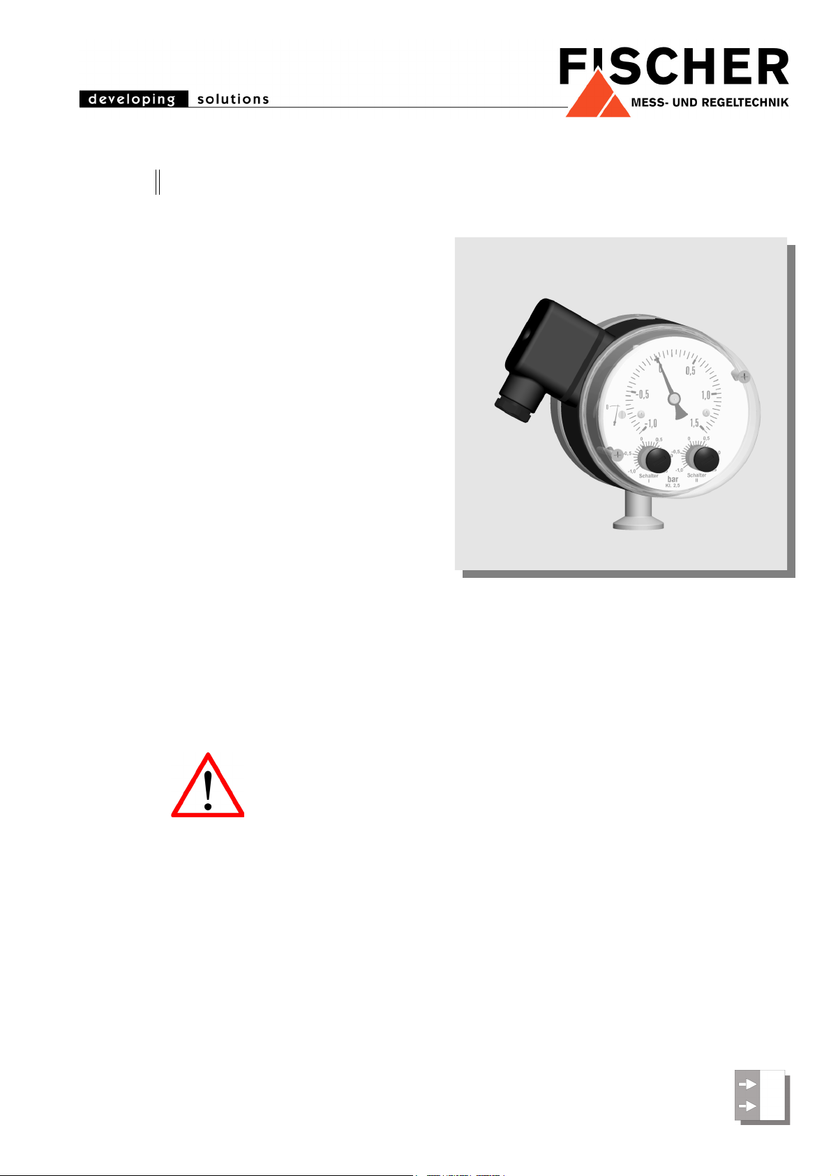
MS10 Contact Pressure Vacuum Gauge
Table of Contents
1. Safety Instructions
2. Intended Applications
3. Product Description and Functions
4. Installation
5. Commissioning
6. Maintenance
7. Transport
8. Service
9. Accessories
10. Disposal
11. Specifications
12. Dimensions
13. Ordering Code
14. Declaration of Conformity
15.7.10 BA_GB_MS10.fm
1. Safety Instructions
1.1. General
This manual contains detailed
information about the product
and instructions for its installation, operation and maintenance.
Operators and other technical
personnel responsible for the equipment must read
this thoroughly before attempting to install or operate this equipment. A copy of this manual must
always be kept accessible at the place of work for
reference by concerned personnel.
Chapter 1 (sections 1.2 through 1.7) contains general as well as specific safety instructions. Chapters
2 through 10, covering topics ranging from intended
purpose of the equipment to its final disposal, also
include important points relating to safety. Overlooking or ignoring any of these safety points can
endanger humans and animals, and possibly cause
damage to other equipment.
1.2. Personnel Qualification
Personnel responsible for installation, operation,
maintenance and inspection of this product must
have the qualifications, training and experience
necessary to carry out such work on this type of
equipment.
1.3. Risks of Disregarding Safety Instructions
Disregarding safety instructions, use of this product
for purposes for which it is not intended, and/or operation of this product outside the limits specified for
any of its technical parameters, can result in harm to
persons, the environment, or the plant on which it is
installed. Fischer Mess- und Regeltechnik GmbH
will not be responsible for consequences in such
circumstances.
Page 2

1.4. Safety Instructions for Operators
1. Measuring diaphragm
2. Motion work
3. Tappet
4. Micro switches,
Operating elements
5. Pressure chamber
Safety instructions for the proper use of this product must
be followed. This information must be available at all times
to personnel responsible for installation, operation, maintenance and inspection of this product. Adequate steps
must be taken to prevent the occurrence of hazardous
conditions that can be caused by electric energy and the
convertible energy of the process media. Such conditions
can, for example, be the result of improper electrical or
process connections. Detailed information is available in
relevant published norms (DIN EN, UVW in Germany;
and equivalents in other countries), industrial standards
such as DVWG, GL-, VDE guidelines, as well as regulations of the local authorities (e.g., EVUs in Germany).
1.5. Modifications Forbidden
Modification or other technical alteration of the product is
not permissible. This also applies to the use of unauthorized spare parts for repair / maintenance of the product.
Any modifications to this product, if and as necessary,
should be done only by Fischer Mess- und Regeltechnik
GmbH.
1.6. Operational Restrictions
The operational reliability of the product is guaranteed
only when used for intended purposes. The product must
be selected and configured for use specifically with
defined process media. The limiting values of operating
parameters, as given in the product specification sheet,
must never be crossed.
1.7. Safety Considerations during Installation and Maintenance
The safety instructions given in this manual, existing national regulations relating to accident prevention and the
internal safety rules and procedures of the user organization regarding safety during installation, operation and
servicing must all be followed meticulously.
It is the responsibility of the users to ensure that only suitably qualified and experienced technical personnel are
used for installation, operation and servicing of this equipment.
3. Product Description and Functions
3.1. Schematic Diagram
3.2. Principles of Operation
The measuring system consists of two encapsulated and
hydraulically coupled metal diaphragm. When subjected
to pressure it causes a deflection proportional to the
strength of pressure. Opposite of the medium-touched
diaphragm a tappet returns the deflection to a motion work
and the operating elements of the micro switches.
When subjected to excessive pressure each metal diaphragm based oneself on the chassis of the capsule.
Therefore the device is prevented from damage.
4. Installation
The instrument is intended for pipe mounting by KF10
small flange pipe connection per DIN 28403 / ISO 2861.
The instrument is factory calibrated while mounted upright, pressure port downward and must be mounted that
way.
2. Intended Applications
Overpressure and vacuum proof contact pressure gauge
for control and supervising purposes in vacuum processes.
The product must be used only for applications and under
conditions specified by Fischer Mess- und Regeltechnik
GmbH.
Please confer with Fischer Mess- und Regeltechnik
GmbH prior to using this instrument along with polluted or
aggressive media. For use with this media it needs to be
adapted in every part with direct contact to the media.
To ensure safety during installation and maintenance integrate adequate shut-off valves. By recommended
accessories the instrument can be
• depressurized or shut down,
• cut off a plant to enable controlling or repairing,
• operational checked on site.
2
Page 3
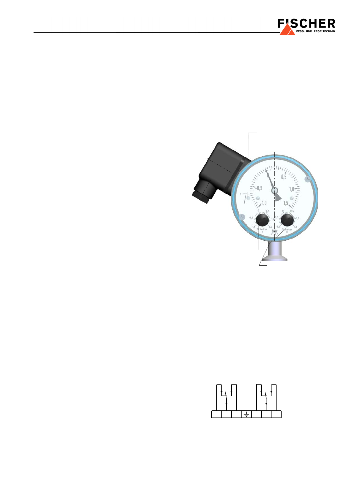
4.1. Process Connection
setting of switching points
zero point adjustment screw
Gerät druck- und spannungslos
6
413
2
S1 S2
5
Instrument pressureless and dead
• Only qualified technicians authorized for this type of
work should undertake installation.
• Only for intended mechanical process connection.
• Ensure that process equipment and pressure lines
are at atmospheric pressure before making pressure
connections.
• The instrument should be provided with suitable pro-
tection against pressure surges (e.g., snubber or
pulsation damper).
• Ensure that the mechanical configuration and mate-
rials of construction of the instrument are compatible
with the process media.
• Ensure that process pressure is always less than the
specified safe pressure rating.
4.2. Electrical Connection
• Only qualified technicians authorized for this type of
work should undertake installation.
• Switch off electrical power to the plant before attempt-
ing electrical installation work of any kind.
• Electrical connections must comply with relevant in-
ternational, national and local regulations and norms
relating to electrical and instrumentation installations.
5.2. Adjustment of Zero Point
• Vent pressure lines to atmosphere.
• Remove cover.
• Set measuring indicator to zero by zero point adjustment screw (see 5.3.).
• Mount cover.
5.3. Location of Zero Point Adjustment Screw and
Setting of Switching Points
• Make electrical connections to the instrument through
a suitable fuse.
5. Commissioning
• Power supply and signal cabling as well as process
connections to the instrument must be correctly selected to meet operational requirements, and installed
in a way that does not cause physical stress to the
instrument.
• The pressure line must have a downward gradient
throughout, from the pressure instrument to the process vessel / pipe. This is to prevent formation of air /
gas pockets (for liquid applications) and liquid plugs
(for air / gas applications). If this continuous downward gradient cannot be provided for any reason,
then suitable water and / or air separation devices
must be inserted in the pressure line.
• The instrument and lines must be protected against
frost when used with water.
• The pressure line must be kept as short as possible
and must not have short bends to avoid measurement
errors induced by pressure line delays.
• Carefully check the pressure-tightness of pressure
connection before start-up.
5.1. Pressure Connection
Pressure connection must be installed in a way that does
not cause physical stress to the instrument.
5.4. Setting of Switching Points
• Unscrew plugs from cover.
• Set desired switching points according to marks on
reference value scale by screwdriver. Achievable
accuracy: 5% FS. More exact settings can be achieved by using accessories like testing manometer,
ohmmeter on site or ex factory.
• Screw plugs in.
5.5. Connection Diagram
3
Page 4

6. Maintenance
The instrument is inherently maintenance-free.
However, to ensure reliable operation and maximize the
operating life of the instrument, it is recommended that the
instrument, its external electrical and process connections
and external connected devices be regularly inspected,
e.g.:
• Check the display.
• Check the switching output connections and external
devices that are connected to these.
• Check all pressure connections for leak-tightness.
• Check the integrity of all electrical connections of the
instruments.
Inspection and test schedules depend on operating and
site conditions. The operating manuals of other equipment
to which the instrument is connected must be read thoroughly to ensure that all of them work correctly when connected together.
7. Transport
The product must be protected against shock and vibration during transport. It must therefore be properly packed,
preferably in the original factory packaging, whenever it is
to be transported.
8. Service
Any defective devices or devices with missing parts
should be returned to Fischer Mess- und Regeltechnik
GmbH. For quick service contact our service department.
Remaining medium in and on dismantled
measuring instruments may cause danger
to persons, environment and equipment.
Take reasonable precautions! Clean the
instrument thoroughly if necessary.
9. Accessories
N.A.
10. Disposal
Protect your environment!
Use the product in accordance with relevant regulations. Please be aware of environmental consequences of disposal
at the end of the product's life, and take
care accordingly.
4
Page 5

11. Specifications
General
Measuring range (s. Ordering Code)
Nominal pressure 25 bar
Max. pressure overpressure proof to nominal pressure (all measuring ranges),
vacuum proof up to fine vacuum 10
Leakage rate
Perm. ambient temperature -10 ... +70°C
Perm. media temperature 70°C
Degree of protection IP54 per DIN EN 60529
Mounting position vertical, pressure port downward
Accuracy ± 2.5% FS
Adjustment of zero point located in the dial
Switching Points
10
10
-7
Pa m³/s
-6
mbar l/s
-2
mbar
Output contacts 1 or 2 micro switches, 1-pole changing contacts
Setting of switching points
adjustable by reference value scale
smallest adjustable value: approx. 5% FS
Switching hysteresis approx. 2.5% FS
Load / contact U ~ max. = 250 V AC, I max. = 5 A, P max. = 250 VA
U = max. = 30 V DC, I max. = 0,4 A, P max. = 10 W
Connections
Electrical Connection cable terminal box
Pressure Connection
KF10 small flange pipe connection DIN 28403 and ISO 2861
Measuring System metal diaphragm measuring system, welded
Materials
Pressure
Measuring
chamber stainless steel 1.4404
diaphragm 1.4571, Duratherm®
Materials, wetted inner parts stainless steel 1.4404, 1.4571
Materials, housing aluminium, eloxadized in black
Materials, front cover macrolon
Weight 2,6 kg
Mounting pipe mounting by KF10 small flange pipe connection per DIN 28403 / ISO 2861
5
Page 6

12. Dimensions (all units in mm unless otherwise stated)
KF10 small flange
pipe connection
cable terminal box
M16 x 1.5 plastic
connection
6
Page 7

13. Ordering Code
0
0
EA 0 00K
K
Contact Pressure
Vacuum Gauge MS10
Measuring range
-200 . . . 200 mbar.................................................. > B 5
0 . . . 400 mbar.................................................. > 8 3
-1 . . . . . 0,6 bar.................................................. > 3 2
-1 . . . . . 1,5 bar.................................................. > 3 3
-1 . . . . . 3 bar.................................................. > 3 4
-1 . . . . . 5 bar.................................................. > 3 5
-1 . . . . . 9 bar.................................................. > 3 6
-1 . . . . 15 bar.................................................. > 3 7
-1 . . . . 24 bar.................................................. > 3 8
Other ranges upon request ..................................... > 9 9
Wetted Parts
1.4404/1.4571 .......................................................................> E
Pressure Chamber
Aluminium, eloxadized in black.....................................................> A
Type
Bottom connection, KF small flange pipe connection ................................. > K
Switching Elements
1 adjustable microswitch.................................................................................... > A
2 adjustable microswitches ................................................................................ > B
Electrical Connection
cable terminal box..................................................................................................... > K
7
Page 8

14. Declaration of Conformity
Technische Änderungen vorbehalten • Subject to change without notice • Changements techniques sous réserve
Fischer Mess- und Regeltechnik GmbH • Bielefelder Str. 37a • D-32107 Bad Salzuflen • Tel. +49 5222 9740 • Fax +49 5222 7170
eMail: info@fischermesstechnik.de • www.fischermesstechnik.de
8
 Loading...