

Page 1

d e v elopi n g s o l u t i o n s
*09005231*
BA_EN_ME49F
Rev.A
08/18
*09005231*
Table of contents
1 Safety instructions
2 Application purpose
3 Product and function description
4 Installation and assembly
5 Start-up
6 Maintenance
7 Transportation
8 Service
9 Accessories
10 Waste disposal
11 Technical Data
12 Dimensional drawings
13 Order codes
15 Attachments
1 Safety instructions
1.1 General
This operating manual contains instructions fundamental to the installation,
operation and maintenance of the device
that must be observed unconditionally. It
must be read by the assembler, operator and the
specialized personnel in charge of the instrument
before it is installed and put into operation. This
operating manual must always be accessible at the
place of installation.
The subsequent sections on general safety instructions 1.2 - 1.7 as well as the following special
instructions ranging from intended use to disposal
2-10 contain important safety instructions the nonobservance of which can cause danger to persons,
animal and physical objects.
1.2 Personnel Qualification
The instrument may only be installed and commissioned by specialized personnel familiar with the
installation, commissioning and operation of this
product.
Specialized personnel are persons who can assess
the work they have been assigned and recognize
potential dangers by virtue of their specialized
training, their skills and experience and their
knowledge of the pertinent standards.
For explosion-proof models the specialized personnel must have received special training or instruction or be authorized to work with explosion-proof
instruments in explosion hazard areas.
1.3 Risks due to Non-Observance of Safety Instructions
Non-observance of these safety instructions, the
intended use of the device or the limit values given
in the technical specifications can be hazardous or
cause harm to persons, the environment or the
plant itself. Fischer Mess- und Regeltechnik GmbH
will not be liable for damage claims if this should
happen.
1.4 Safety Instructions for the Operating
Company and the Operator
The safety instructions governing correct operation
of the instrument must be observed. The operating
company must make them available to the installation, maintenance, inspection and
operating personnel. Dangers arising
from electrical components, energy
Operating Manual
ME49F
Pressure Transmitter
for applications in explosive areas
According to ATEX Directive 2014/34/EU
Gas explosion protection zone 1
Page 2
2 | 20 Page
discharged by the medium, escaping medium and
incorrect installation of the instrument must be
eliminated. For more information, please see the
applicable national and international regulations,
such as DIN, EN, accident prevention regulations
(UVV) and - for industry-specific individual applications - also in the industry guidelines issued by the
DVWG, Ex, GL, etc. as well as VDE and local
EVUs.
The instrument must be decommissioned and
secured against inadvertent re-operation if a situation arises in which it must be assumed that safe
operation is no longer possible. Reasons for this
assumption could be:
evident damage to the instrument
failure of the electrical circuits
long storage in temperatures over 85°C
considerable strain due to transport
Repairs may be carried out by the manufacturer
only.
A professional single conformity inspection as per
DIN EN 61010, section 1, must be carried out
before the instrument can be re-commissioned.
This inspection must be performed at the manufacturer's location. Correct transport and storage of the
instrument are required.
1.5 Unauthorised Modification
Modifications of or other technical alterations to the
instrument by the customer are not permitted. This
also applies to replacement parts. Any modifications/alterations required will be carried out by
Fischer Mess- und Regeltechnik GmbH only.
1.6 Impermissible modes of operation
The operational safety of this instrument can only
be guaranteed if it is used as intended. The instrument model must be suitable for the medium used
in the system. The limit values given in the technical
data may not be exceeded.
1.7 Safe working practices for maintenance and installation work
The safety instructions given in this operating
manual, any nationally applicable regulations on
accident prevention and any of the operating company's internal work, operating and safety guidelines must be observed.
The operating company is responsible for ensuring
that all required maintenance, inspection and installation work is carried out by qualified specialized
personnel.
1.8 Pictogram explanation
WARNING!
… indicates a potentially dangerous
situation, non-observance of which
could endanger persons, animals, the
environment or objects.
INFORMATION!
… highlights important information
efficient and smooth operation.
TIP!
… indicates recommendations that are
not specifically necessary in certain
situations but which could be useful.
2 Application purpose
The two-line pressure transmitter ME49F* serves
precise recording of a pressure with a resistance
pressure cell in the ex-area.
The supply circuit on terminals 1 and 2
must correspond to ignition protection
type 'Inherent safety' of category 'ib'.
The units are may only be used for the purpose
defined by the manufacturer in the data sheet or
operating instructions.
The maximum allowed temperature
range from -20°C to +60°C may not be
exceeded.
If there is dirty or aggressive media in the system,
or if this is to be expected, the device must be
modified in terms of those parts that come into
contact with the media. Please talk to the manufacturer first before ordering.
The corresponding setup regulations are
to be considered for each application
case.
Designation as per guideline 2014/34/EU
II 2G Ex ib IIC T6 Gb
Page 3
3 | 20 Page
3 Product and function description
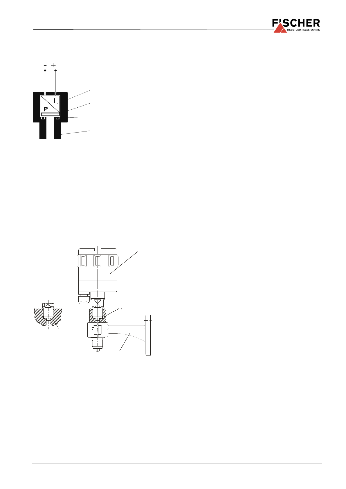
3.1 Function diagram
3.2 Design and mode of operation
The measuring pressure acts on a ceramic membrane that deforms when under pressure.
The output signal on the measurement bridge
attached to rear of the membrane changes when
the membrane deforms.
Electronics integrated into the pressure transmitter
housing converts the sensor signal into an electronic uniform signal 4...20mA um.
4 Installation and assembly
As standard, the unit has a cylindrical pipe thread
and flat seal for screwing into the screw holes.
Wall assembly is possible when the wall holder
MZ310* is used.
The manometer screw connections MZ27* allow
pipes to be connected directly.
The device is set ex-works for vertical installation,
however any installation position is possible. In
installation positions that vary from the vertical, the
zero-point can be corrected using the installed zeropoint potentiometer (5.1).
To guarantee safe working conditions during installation and maintenance, suitable stop valves must
be fitted in the system. The shutoff valves of the
Fischer series MZ5* make it possible to
depressurize or decommission the unit,
or to disconnect it from the power supply within
the applicable system for repairs or inspections
or to check the functions of the unit on site.
Thanks to their venting screws, the shut-off valves
allow the connected pipe system to be vented.
4.1 Process connection
Dangers caused by pressure on the instrument are
to be prevented with suitable measures.
By authorized and qualified specialized person-
nel only.
Only for the designated mechanical process
connection - for the model, see the order code
on the device type plate.
The pipes need to be depressurized when the
device is being connected.
Appropriate steps must be taken to protect the
device from pressure surges.
Check the suitability of the device for the media
to be measured.
Observe the maximum pressure.
The pressure measuring line must be installed
on a gradient so that no air pockets e.g. for liquid measurements or water pockets e.g. for gas
measurements can be created. If the required
incline is not reached, water and/or air filters
need to be installed at suitable points.
The pressure sensing lines need to be kept as
short as possible and installed without sharp
bends to avoid interfering delay times.
4.2 Pressure surge absorption
Dangers caused by pressure on the instrument are
to be prevented with suitable measures.
Pulsating pressure on the system side can lead to
functional problems. As a protective measure, we
recommend the installation of damping elements in
the pressure connection lines.
1
3
2
4
1
Connecting shanks
2
Measuring cell
3
O-ring
4
Transformation
MZ290*
MZ310*
Sealing disc
MZ290*
ME49F*
Page 4
4 | 20 Page
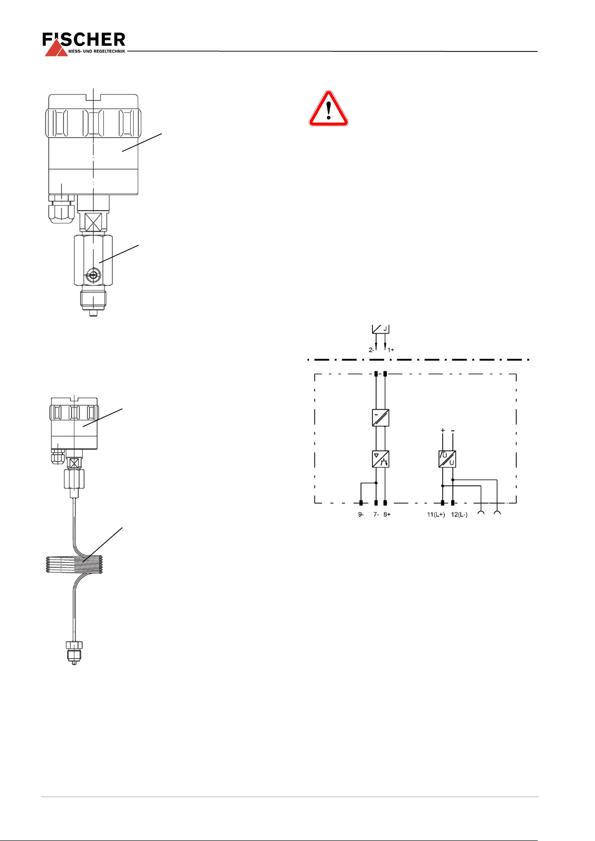
4.2.1 For gas-like media
Fig. 1 Damping reactor MZ41*
When operational, set the throttle needle so that the
output signal is settled as required.
4.2.2 In the case of fluid media
Fig. 2 Capillary throttle coils MZ40*
4.3 Electrical connections
The ME49F* is an intrinsically-safe piece
of equipment for use in potentially explosive areas. For connection of the intrinsically safety supply current circuit, the
details in the type approval certificate apply.
For ex-operations, observe the electrical data of
the EC type examination certificate (see attachment) and the local applicable regulations
and guidelines for the installation and operation
of electrical installations in potentially explosive
areas.
By authorized and qualified specialized person-
nel only.
Disconnect the system from the mains before
connecting the device.
Add a fuse adapted to the energy requirements.
5 Start-up
All electrical supply, operating and measuring
lines and the pressure connections must have
been correctly installed before commissioning.
All supply lines are arranged so that there are
no mechanical forces acting on the device.
Check that the pressure connections do not
leak before commissioning.
ME49F*
MZ41*
MZ40*
ME49F*
Output
Net-
Power Rail
certified, intrinsi-
cally-safe
power unit
Pressure transmitter ME49F
Ex-area
Not ex
-area
Page 5
5 | 20 Page
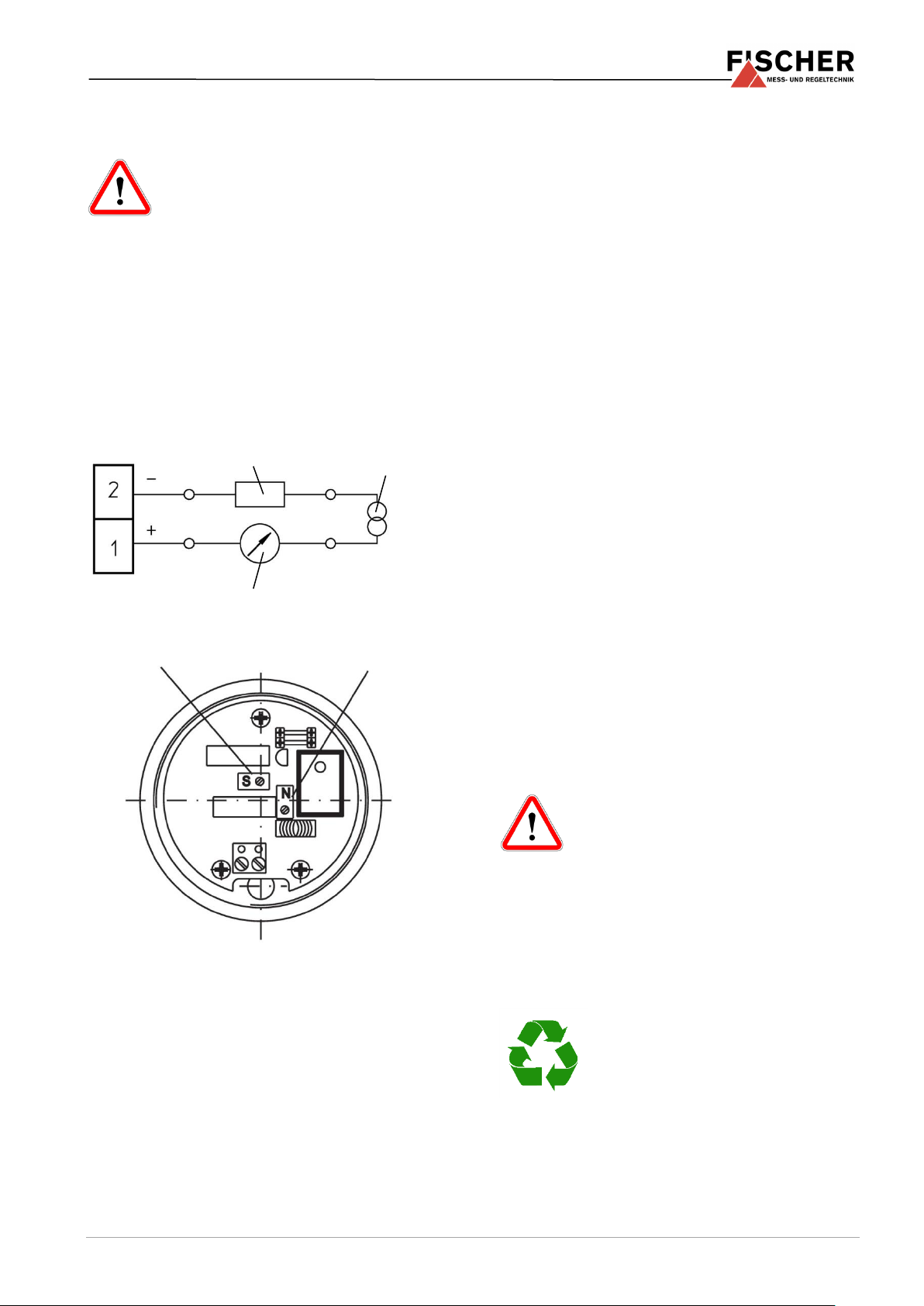
5.1 Zero point and measuring range adjustment
Please note that adjustments can only
be carried out in ex-free zone.
The pressure transmitters are set in the factory
before delivery so that they do not usually need to
be adjusted at the assembly site. If the output signal
does need to be adjusted, this can be undertaken
using the 'S' and 'N' potentiometers.
The potentiometers can be accessed by unscrewing the lid of the housing. The unit is connected to
the power supply as shown on the wiring diagram
and also, an ammeter is connected between the
pressure transmitter and the auxiliary energy
source.
Fig. 3 Measuring switch
Fig 4 Setting potentiometer
5.2 Adjustment sequence:
Switch on auxiliary energy
Depressurize the measuring system: p = 0
Display for std. measuring ranges = 4.0 mA
In the case of any deviations, the output signal
of the pressure transmitter shown by the ammeter can be corrected with the zero-point potentiometer (N).
Set the pressure in the measuring system to
the measuring range end value (e.g. pressure
is generated by means of a manual pump and
pressure compensation unit) Display 20 mA. In
case of differences, correct by adjusting the
voltage potentiometer (S).
Then check the zero-point and measuring
range again; correct if necessary.
6 Maintenance
The instrument is maintenance-free.
We recommend checking the instrument at regular
intervals to ensure reliable operation and a long
service life.
Inspecting the output signal.
Check the leak-tightness of the pressure con-
nection lines.
Check the electrical connection (cable clamp
connections).
The precise test cycles and operating and ambient
conditions need to be adjusted. If various instrument components interact, the operating instructions of all the other instruments also need to be
observed.
7 Transportation
The measuring device must be protected against
impacts. It may only be transported in packaging
specifically intended for transport.
8 Service
All defective or faulty devices should be sent directly to our repair department. We would ask you to
please coordinate all return shipments with our
sales department so that we can ensure
careful processing of all faulty devices
for our customers.
Process media residues in and
on dismantled devices can be a hazard to people,
animals and the environment. Take adequate
preventive measures. If required, the devices must
be cleaned thoroughly.
9 Accessories
Not planned
10 Waste disposal
For the sake of the environment ....
Please help to protect our environment and dispose of or recycle used instruments as
stipulated by the applicable regulations.
Auxiliary energy
Apparent ohmic resistance
Span
Zero point
Ampere meter
Page 6

6 | 20 Page
11 Technical Data
Measuring range
40 mbar
60 mbar
100 mbar
160 mbar
250 mbar
400 mbar
600 mbar
1 bar
Overpressure-proof
4 bar
4 bar
4 bar
6 bar
6 bar
6 bar
10 bar
4 bar
Measuring range
1.6 bar
2.5 bar
4 bar
6 bar
10 bar
16 bar
25 bar
40 bar
Overpressure-proof
4 bar
8 bar
8 bar
12 bar
32 bar
32 bar
60 bar
60 bar
Ambient conditions
Admissible ambient temperature
-20° to +60°C
Permissible medium temperature
-20° to +60°C
Admissible storage temperature
-30° to +70°C
Electrical data
Rated Voltage
24 V DC
Allowed operating voltage Ub
15 … 30 V DC
Limit value of the supply power circuit
Voltage Ui
≤ 30 V
Current Ii
≤ 100 mA
Output Pi
≤ 750 mW
effective inner capacity Ci
15 nF
effective inner inductivity Li
90 mH
Capacity between the power circuit and housing.
≤ 2.2 nF
Output signal
4... 20 mA
Electrical connection type
Two-wire
Load at rated voltage
450
Apparent ohmic resistance
RL [] (Ub-15 V) / 0.02 A
Current/voltage limit
ca. 30 mA
Temperature drift, zero-point
0.4 % FS/10 K
Temperature drift, measuring range
0.05 % FS/10 K
Linearity
± 0.5% of the measuring range
Hysteresis
<0.1% of the measuring range
Connection, materials, assembly
Discharge port
Connection shank G1/2B acc. to DIN EN 837
Electrical connection
Inside screw terminal, cable screw connection M16 x 1.5
Protection
IP 65 acc. to DIN EN 60529
Materials of parts that come into contact with the
medium
Chromium nickel steel 1.4571, ceramic, FPM
Casing material
Aluminium, painted
Assembly
Tap of sleeve assembly acc. to DIN EN 837
Wall assembly using the wall holder MZ310* and manometer adapter MZ290*
Manometer screw connections MZ27* allow pipes to be connected directly
Identification
0044
II 2G Ex ib IIC T6 Gb
EC Examination Certificate
BVS 03 ATEX E 414
Page 7

7 | 20 Page
12 Dimensional drawings
(all dimensions in mm unless otherwise specified)
Cable screw connection
M16 x 1.5
Page 8

8 | 20 Page
13 Order codes
Pressure Transmitter
Type ME49
F 8 7 B E A 0 0 0 0
EXECUTION
Version in Fischer field housing ............................................................ >
F
Measuring range
-25… 25 mbar .......................................................................................... >
B 2
0… 40 mbar ............................................................................................ >
5 7
0… 60 mbar ............................................................................................ >
5 8
0… 100 mbar ........................................................................................... >
5 9
0… 160 mbar ........................................................................................... >
6 0
0… 250 mbar ........................................................................................... >
8 2
0… 400 mbar ........................................................................................... >
8 3
0…0.6 bar ............................................................................................ >
0 1
0…1 bar ............................................................................................ >
0 2
0 …1.6 bar ............................................................................................ >
0 3
0…2.5 bar ............................................................................................ >
0 4
0…4 bar ............................................................................................ >
0 5
0…6 bar ............................................................................................ >
0 6
0…10 bar ............................................................................................ >
0 7
0…16 bar ............................................................................................ >
0 8
0…25 bar ............................................................................................ >
0 9
0…40 bar ............................................................................................ >
1 0
-1…0 bar ............................................................................................ >
3 1
-1… 0.6 bar ............................................................................................ >
3 2
-1… 1.5 bar ............................................................................................ >
3 3
-1…3 bar ............................................................................................ >
3 4
-1…5 bar ............................................................................................ >
3 5
-1…9 bar ............................................................................................ >
3 6
-1…15 bar ............................................................................................ >
3 7
Discharge port
Connecting pin with outer thread G1/2B bottom, Niro ............................................. >
8 7 Electrical output signal
4 - 20 mA linear, 2-LINE. ..................................................................................................... >
B Electrical connection
Inner terminal strip..................................................................................................................... >
E
Operating voltage
15 - 30 V DC ................................................................................................................................... >
A
Page 9

9 | 20 Page
15 Attachments
Page 10

10 | 20 Page
Page 11

11 | 20 Page
Page 12

12 | 20 Page
Page 13

13 | 20 Page
Page 14

14 | 20 Page
Page 15

15 | 20 Page
Page 16

16 | 20 Page
Page 17

17 | 20 Page
Page 18

18 | 20 Page
Page 19

19 | 20 Page
Page 20

Technische Änderungen vorbehalten • Subject to change without notice • Changements techniques sous réserve
Fischer Mess- und Regeltechnik GmbH • Bielefelder Str. 37a • D-32107 Bad Salzuflen • Tel. +49 5222 9740 • Fax +49 5222 7170
eMail: info@fischermesstechnik.de • www.fischermesstechnik.de
 Loading...