

Page 1

d e v e l oping s o l u t i o n s
*09005086* DB_BA_EN_ME01_R Rev.A 12/16
*09005086*
Data Sheet and Operating Manual
ME01
Digital manometer
ME01 ## # 87 # HL R####
Gas explosion protection zone 2
Table of Contents
1 Safety guidelines
2 Application purpose
3 Product and function description
4 Installation and assembly
5 Commissioning
6 Maintenance
7 Transportation
8 Service
9 Accessories
10 Waste disposal
11 Technical Data
12 Dimensional drawings
13 Order Codes
14 Attachments
1 Safety guidelines
1.1 General Information
This operating manual contains instructions fundamental to the installation, operation and maintenance of the device
that must be observed unconditionally. It
must be read by the assembler, operator and the
specialized personnel in charge of the instrument
before it is installed and put into operation. This operating manual must always be accessible at the
place of installation.
The subsequent sections on general safety instructions 1.2 - 1.7 as well as the following special instructions ranging from intended use to disposal 210 contain important safety instructions the nonobservance of which can cause danger to persons,
animal and physical objects.
1.2 Personnel Qualification
The instrument may only be installed and commissioned by specialized personnel familiar with the installation, commissioning and operation of this
product.
Specialized personnel are persons who can assess
the work they have been assigned and recognize
potential dangers by virtue of their specialized train-
ing, their skills and experience and their knowledge
of the pertinent standards.
For explosion-proof models the specialized personnel must have received special training or instruction or be authorized to work with explosion-proof
instruments in explosion hazard areas.
1.3 Risks due to Non-Observance of Safety Instructions
Non-observance of these safety instructions, the intended use of the device or the limit values given in
the technical specifications can be hazardous or
cause harm to persons, the environment or the
plant itself. The supplier of the equipment will not be
liable for damage claims if this should happen.
1.4 Safety Instructions for the Operating Company and the Operator
The safety instructions governing correct operation
of the instrument must be observed. The operating
company must make them available to the installation, maintenance, inspection and operating personnel. Dangers arising from electrical components,
energy discharged by the medium, escaping medium and incorrect installation of the instrument must
be eliminated. The particulars can be
found in the respective regulations
such as DIN, EN, explosion hazard,
Page 2
WARNING!
… indicates a potentially dangerous
situation, non-observance of which
could endanger persons, animals, the
environment or objects.
INFORMATION!
… highlights important information efficient and smooth operation.
TIP!
… indicates recommendations that are
not specifically necessary in certain
situations but which could be useful.
accident prevention regulations and also in the industry guidelines issued by the DVWG, GL, etc.
and the VDE as well as the local EVUs.
The instrument must be decommissioned and secured against inadvertent re-operation if a situation
arises in which it must be assumed that safe operation is no longer possible. Reasons for this assumption could be:
• evident damage to the instrument
• failure of the electrical circuits
• long storage in temperatures over 85°C
• considerable strain due to transport
Repairs may be carried out by the manufacturer only.
A professional single conformity inspection as per
DIN EN 61010, section 1, must be carried out before the instrument can be re-commissioned. This
inspection must be performed at the manufacturer's
location. Correct transport and storage of the instrument are required.
1.5 Unauthorised Modification
Modifications of or other technical alterations to the
instrument by the customer are not permitted. This
also applies to replacement parts. Any modifications/alterations required will be carried out by
Fischer Mess- und Regeltechnik GmbH only.
1.6 Impermissible modes of operation
The operational safety of this instrument can only
be guaranteed if it is used as intended. The instrument model must be suitable for the medium used
in the system. The limit values given in the technical
data may not be exceeded.
1.7 Safe working practices for maintenance and installation work
The safety instructions given in this operating manual, any nationally applicable regulations on accident prevention and any of the operating company's
internal work, operating and safety guidelines must
be observed.
The operating company is responsible for ensuring
that all required maintenance, inspection and installation work is carried out by qualified specialized
personnel.
1.8 Explanation of symbols
2 Application purpose
Electronic manometer for measuring over-pressure
and under-pressure of fluid and gas-like measuring
substances. The device is to be exclusively used for
the applications agreed between the manufacturer
and the user.
Explosion hazard area classification
The digital manometers ME01 are suitable for use
as 'Electrical equipment for use in areas with combustible gases', zone 2.
Designation as per guideline 2014/34/EU
II 3G Ex nA IIC T4
3 Product and function description
3.1 Design and mode of operation
A ceramic measuring cell acts as the pressure
transducer. The high resistance of the ceramic materials that are used allow use even for aggressive
media. There is a resistance measuring bridge attached to the side of the measuring diaphragm that
faces away from the medium. When pressure is exerted, the membrane distorts in the elastic range. t
the same time, the resistance values of the bridge
change proportionally to the measuring pressure.
These values are implemented and displayed by
the installed electronics. There are electrical uniform signals 0/4…20 mA and 0…10 V in a 3-wire
system available for remote transmission.
Page 3
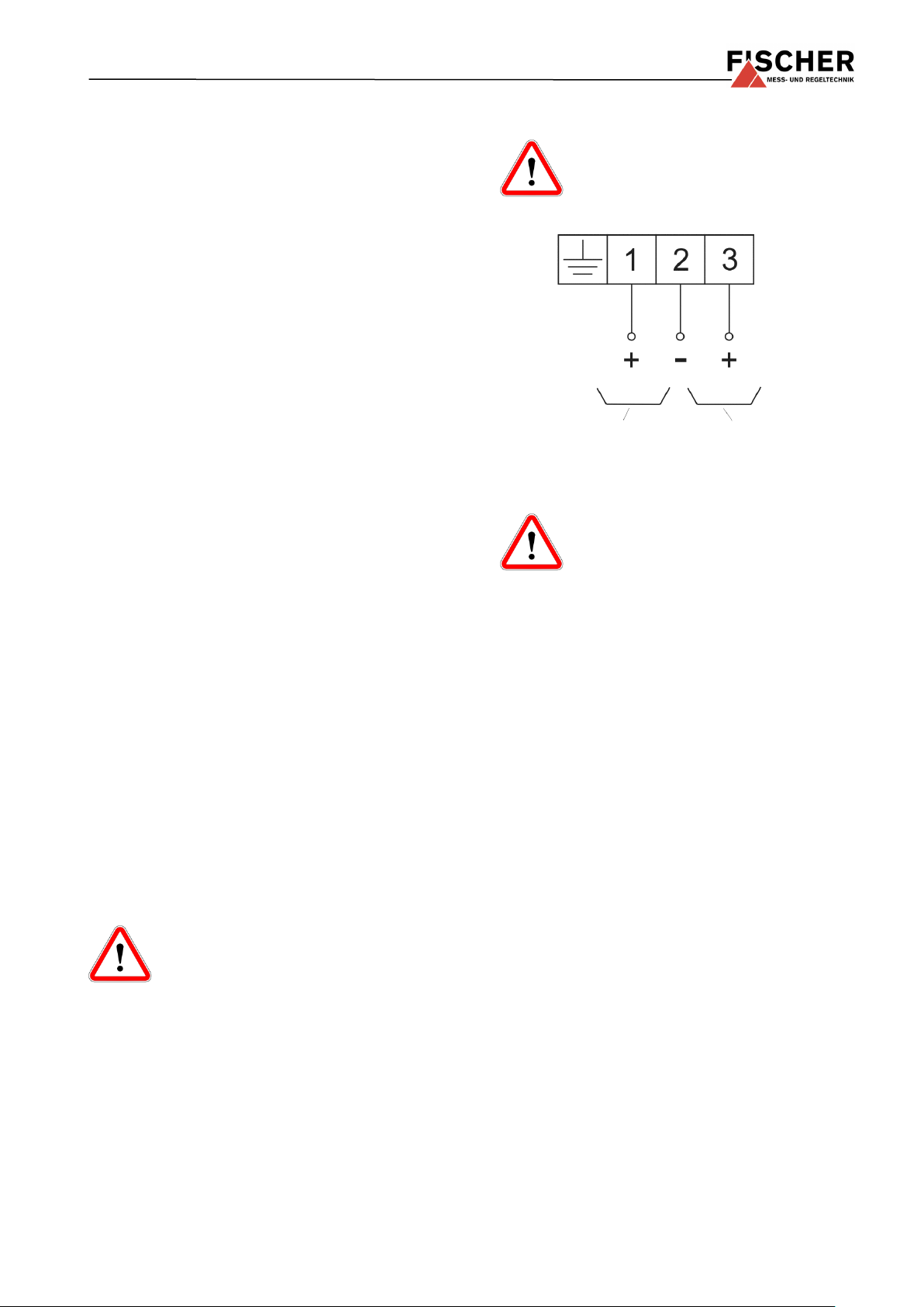
Three-conductor circuit
output
Signal
Operating
voltage
4 Installation and assembly
As standard, the device with the connecting port for
connection to pipes and other connection parts,
such as the welding sleeve, union nut with soldering
and welding nipples, is equipped with soldering and
welding nipples (see data sheet MZ...). It can be
mounted to a wall using the wall bracket (see data
sheet MZ...). Manometer screw connections for 10,
8, 6 mm dia. pipes can be supplied for connection
to pipes.The enclosure protection type IP 65 is only
guaranteed, if a suitable power supply cable is
used.
4.1 Process connection
• By authorized and qualified specialized person-
nel only.
• Only for the designated mechanical process
connection - for the model, see the order code
on the device type plate.
• The pipes need to be depressurized when the
device is being connected.
• Do not mount the device against existing water
columns, and secure suitably against pressure
surges.
• Use only with media suitable for operation.
• Observe the maximum pressure.
• Check that the pressure connections do not
leak before commissioning.
4.2 Electrical connection
• By authorized and qualified specialized person-
nel only.
• Disconnect the system from the mains before
connecting the device.
• Do not take out the connecting plug while ener-
gized
Explosion protection instructions
To guarantee safe operation of the instrument, the supply circuit must satisfy
the requirements for zone 2, category 3,
and the locally applicable regulations
and guidelines for the installation and operation of
electrical systems in explosion hazard areas (e.g.
EN 60079-0).
4.3 Wiring diagram
Do not take out the connecting plug
while energized
Static electricity
The case must be equipped with an
earth connection to reduce the surface
resistance.
5 Commissioning
• All electrical supply, operating and measuring
lines, and the pressure connections must have
been correctly installed before commissioning.
All supply lines are arranged so that there are
no mechanical forces acting on the device.
• If liquid measuring media are used the pressure
connection line must be vented, as liquid columns of different heights in the pipes can cause
measuring errors. The instrument must be protected against frost if water is used as a medium.
• The pressure sensing lines must be installed on
an incline so that no condensation pools can
form.
• The pressure sensing lines need to be kept as
short as possible and installed without sharp
bends to avoid interfering delay times.
• Appropriate shutoff valves must be provided to
ensure safety during installation, maintenance
and inspection
The supply voltage may not exceed 30 V DC. The
supply circuit must be protected by a slow 200 mA
fuse. Only a CE-compliant power supply unit may
be used as a power supply.
Page 4

6 Maintenance
The instrument is maintenance-free.
We recommend checking the instrument at regular
intervals to ensure reliable operation and a long
service life.
• Inspecting the output signal.
• Check the leak-tightness of the pressure con-
nection lines.
• Check the electrical connection (cable clamp
connections).
The precise test cycles and operating and ambient
conditions need to be adjusted. If various instrument components interact, the operating instructions of all the other instruments also need to be
observed.
7 Transportation
The measuring device must be protected against
impacts. It may only be transported in packaging
specifically intended for transport.
8 Service
All defective or faulty devices should be sent directly to our repair department. We would ask you to
please coordinate all return shipments with our
sales department so that we can ensure careful
processing of all faulty devices for our customers.
Measuring residues in and on dismantled devices can be a hazard to people,
animals and the environment. Take adequate preventive measures. If required,
the devices must be cleaned thoroughly.
9 Accessories
• Manometer accessories acc. to data sheet
MZ...
10 Waste disposal
For the sake of the environment ....
Please help to protect our environment and dispose of or recycle used
instruments as stipulated by the applicable regulations.
Page 5

Measuring range in bar
0-1.6
0-2.5
0-4
0-6
0-10
0-16
0-25
0-40
0-60
Overpressure-proof in bar
3.2 5 8
12
20
32
50
80
120
Permissible ambient temperature
-10°C 60°C
Admissible medium temperature
Max. 60°C
Pressure connection
Connection ports with external thread
G½ B stainless steel, rustproof
Electrical connection
Standardised plug DIN EN 175 301-803-A
Protection class:
IP 65 acc. to DIN EN 60529
Parts in contact with the medium
AISI 316L (1.4404), Seal: Viton®
Material: Casing
AISI 304 (1.4305)
Electrical data
Power supply
Only CE-compliant power supply units with a slow 200 mA
fuse may be used.
Rated voltage
24V DC
Allowed operating voltage Ub
15....30 V DC
inner effective capacity Ci
max. 270nF
effective inner inductivity Li
max. 980H
Electrical connection type
Three-conductor
Output signal
0..20 mA / 4..20 mA / 0..10 V
Load at rated voltage
450
Current/voltage limit
for output 0..10V: ca. 10.5 V
for output 0/4..20 mA: ca. 24 mA
Zero-point, temperature drift
0.4 % FS/10 K
Measuring range, temperature drift
0.05 % FS/10 K
Linearity
< 1 % of the measuring range
Hysteresis
< 0.5 % of the measuring range
Identification acc. to
ATEX guideline 2014/34/EU
II 3G Ex nA IIC T4
Measuring range in bar
- 1..0
-1..0.6
-1..1.5
-1..3
-1..5
-1..9
-1..15
0...-1
Overpressure-proof in bar
2 3 3 8 12
20
32
2
11 Technical Data
Page 6

M16 x 1.5
Manometer connection port G1/2
nach DIN EN 837
SW22
12 Dimensional drawings
(all dimensions in mm unless otherwise specified)
Page 7

Digital manometer
Type ME01
8 7 H L R####
Measuring range
0 ... 1 bar ............................................... >
0 2
0 ...1.6 bar ............................................... >
0 3
0 ...2.5 bar ............................................... >
0 4
0 ... 4 bar ............................................... >
0 5
0 ... 6 bar ............................................... >
0 6
0 ... 10 bar ............................................... >
0 7
0 ... 16 bar ............................................... >
0 8
0 ... 25 bar ............................................... >
0 9
0 ... 40 bar ............................................... >
1 0
0 ... 60 bar ............................................... >
1 1
-1 ... 0 bar ............................................... >
3 1
-1 ...0.6 bar ............................................... >
3 2
-1 ...1.5 bar ............................................... >
3 3
-1 ... 3 bar ............................................... >
3 4
-1 ... 5 bar ............................................... >
3 5
-1 ... 9 bar ............................................... >
3 6
-1 ... 15 bar ............................................... >
3 7
Measurement accuracy
Characteristic curve dev. Relative pressure 1.0 ............>
M
Characteristic curve dev. Absolute pressure 1.0 ............>
S
Discharge port
Connection ports with external thread G½ B bottom,
Stainless steel ............................................................. >
8
7
Electrical output signal
0 – 20 mA 3-wire (STANDARD) .................................................... >
A
0 – 10 V DC 3-wire (STANDARD) ................................................. >
C
4 – 20 mA 3-wire (STANDARD) .................................................... >
P
Electrical connection
Plug 4-pin, standardised plug DIN EN 175 301-803-A .............. >
H
Operating voltage
24 V DC / AC ............................................................................................. >
L
Customer-specific no.
Code for use in Zone 2 -
Risk from vapours: II 3G Ex nA IIC T4 ........................................................ >
R####
13 Order Codes
Page 8

14 Attachments
Technische Änderungen vorbehalten • Subject to change without notice • Changements techniques sous réserve
Fischer Mess- und Regeltechnik GmbH • Bielefelder Str. 37a • D-32107 Bad Salzuflen • Tel. +49 5222 9740 • Fax +49 5222 7170 •
eMail: info@fischermesstechnik.de • www.fischermesstechnik.de
 Loading...