

FISCHER MA15F ... A Series, MA15F ....B Series, MA15F ... C Series, MA15F ... D Series, MA15F ... 0 Series Operation Manual
Page 1

Operation manual
MA15F ... A/B/C/D
Diaphragm manometer
for explosive areas
Gas explosion protection zone 1 and 2, gases and vapours
Dust explosion protection zone 21 and 22, dry dusts
09015053 • BA_EN_MA15_ATEX • Rev. ST4-D • 03/18
*09015053*
Page 2

| Masthead FISCHER Mess- und Regeltechnik GmbH
2 / 36 BA_EN_MA15_ATEX
Masthead
Manufacturer:
FISCHER Mess- und Regeltechnik GmbH
Bielefelderstr. 37a
D-32107 Bad Salzuflen
Telephone: +49 5222 974 0
Telefax: +49 5222 7170
eMail: info@fischermesstechnik.de
web: www.fischermesstechnik.de
Technical editorial team:
Documentation representative: T. Malischewski
Technical editor: R. Kleemann
All rights, also those to the translation, reserved. No part of this document may
be reproduced or processed, duplicated or distributed using electronic systems
or any other form (print, photocopy, microfilm or another process) without the
written consent of the company FISCHER Mess- und Regeltechnik GmbH, Bad
Salzuflen.
Reproduction for internal use is expressly allowed.
Brand names and procedures are used for information purposes only and do
not take the respective patent situation into account. Great care was taken
when compiling the texts and illustrations; Nevertheless, errors cannot be ruled
out. The company FISCHER Mess- und Regeltechnik GmbH will not accept any
legal responsibility or liability for this.
Subject to technical amendments.
© FISCHER Mess- und Regeltechnik 2016
Version history
Rev. ST4-A 11/16 Version 1 (first edition)
Rev. ST4-B 08/17 Version 2 (Correction)
Rev. ST4-C 08/17 Version 3 (Correction)
Rev. ST4-D 03/18 Version 4 (update)
Page 3

FISCHER Mess- und Regeltechnik GmbH Table of Content
BA_EN_MA15_ATEX 3 / 36
Table of Content
1 Safety information .......................................................................................................................................... 4
1.1 General .....................................................................................................................................................4
1.2 Personnel Qualification.............................................................................................................................4
1.3 Risks due to Non-Observance of Safety Instructions ...............................................................................4
1.4 Safety Instructions for the Operating Company and the Operator............................................................4
1.5 Unauthorised Modification ........................................................................................................................5
1.6 Inadmissible Modes of Operation .............................................................................................................5
1.7 Safe working practices for maintenance and installation work .................................................................5
1.8 Pictogram explanation ..............................................................................................................................6
2 Product and functional description .............................................................................................................. 7
2.1 Delivery scope ..........................................................................................................................................7
2.2 Product summary......................................................................................................................................7
2.3 Intended use .............................................................................................................................................8
2.4 Function diagram ......................................................................................................................................9
2.5 Design and mode of operation..................................................................................................................9
3 Assembly.......................................................................................................................................................10
3.1 Generalities.............................................................................................................................................10
3.2 Process connection ................................................................................................................................10
3.3 Electrical connections .............................................................................................................................12
3.4 Use in areas at risk of explosion.............................................................................................................13
4 Commissioning.............................................................................................................................................17
4.1 General ...................................................................................................................................................17
4.2 Zero point correction...............................................................................................................................17
4.3 Switch point setting.................................................................................................................................18
4.4 Units with a rotation angle transducer ....................................................................................................18
5 Servicing .......................................................................................................................................................19
5.1 Maintenance ...........................................................................................................................................19
5.2 Transport ................................................................................................................................................19
5.3 Service....................................................................................................................................................19
5.4 accessories.............................................................................................................................................19
5.5 Disposal ..................................................................................................................................................20
6 Technical Data .............................................................................................................................................. 21
6.1 Standard version.....................................................................................................................................21
6.2 Options ...................................................................................................................................................22
6.3 Dimensional drawings.............................................................................................................................23
7 Order Codes..................................................................................................................................................27
8 Attachments..................................................................................................................................................30
Page 4

1 | Safety information FISCHER Mess- und Regeltechnik GmbH
4 / 36 BA_EN_MA15_ATEX
1 Safety information
1.1 General
WARNING
This operating manual contains instructions fundamental to the installation, operation and maintenance of the device that must be observed unconditionally. It
must be read by the assembler, operator and the specialized personnel in
charge of the instrument before it is installed and put into operation.
This operating manual is an integral part of the product and therefore needs to
be kept close to the instrument in a place that is accessible at all times to the responsible personnel.
The following sections, in particular instructions about the assembly, commissioning and maintenance, contain important information, non-observance of
which could pose a threat to humans, animals, the environment and property.
The instrument described in these operating instructions is designed and manufactured in line with the state of the art and good engineering practice.
1.2 Personnel Qualification
The instrument may only be installed and commissioned by specialized personnel familiar with the installation, commissioning and operation of this product.
Specialized personnel are persons who can assess the work they have been
assigned and recognize potential dangers by virtue of their specialized training,
their skills and experience and their knowledge of the pertinent standards.
WARNING
For explosion-proof models the specialized personnel must have received special training or instruction or be authorized to work with explosion-proof instruments in explosion hazard areas.
1.3 Risks due to Non-Observance of Safety Instructions
Non-observance of these safety instructions, the intended use of the device or
the limit values given in the technical specifications can be hazardous or cause
harm to persons, the environment or the plant itself.
The supplier of the equipment will not be liable for damage claims if this should
happen.
1.4 Safety Instructions for the Operating Company and the Operator
The safety instructions governing correct operation of theinstrument must be
observed. The operating company must make them available to the installation,
maintenance, inspection and operating personnel.
Dangers arising from electrical components, energy discharged by the medium,
escaping medium and incorrect installation of the device must be eliminated.
See the information in the applicable national and international regulations.
Please observe the information about certification and approvals in the Technical Data section.
The instrument must be decommissioned and secured against inadvertent reoperationif a situation arises in which it must be assumed that safe operation is
no longer possible. Reasons for this assumption could be:
Page 5

FISCHER Mess- und Regeltechnik GmbH Safety information | 1
BA_EN_MA15_ATEX 5 / 36
• evident damage to the instrument
• failure of the electrical circuits
• longer storage outside the approved temperature range.
• considerable strain due to transport
Repairs may be carried out by the manufacturer only.
A professional single conformity inspection as per DIN EN 61010, section 1,
must be carried out before the instrument can be re-commissioned. This inspection must be performed at the manufacturer's location. Correct transport and
storage of the instrument are required.
1.5 Unauthorised Modification
Modifications of or other technical alterations to the instrument by the customer
are not permitted. This also applies to replacement parts. Only the manufacturer
is authorised to make any modifications or changes.
1.6 Inadmissible Modes of Operation
The operational safety of this instrument can only be guaranteed if it is used as
intended. The instrument model must be suitable for the medium used in the
system. The limit values given in the technical data may not be exceeded.
The manufacturer is not liable for damage resulting from improper or incorrect
use.
1.7 Safe working practices for maintenance and installation work
The safety instructions given in this operating manual, any nationally applicable
regulations on accident prevention and any of the operating company's internal
work, operating and safety guidelines must be observed.
The operating company is responsible for ensuring that all required maintenance, inspection and installation work is carried out by qualified specialized personnel.
Page 6
1 | Safety information FISCHER Mess- und Regeltechnik GmbH
6 / 36 BA_EN_MA15_ATEX
1.8 Pictogram explanation
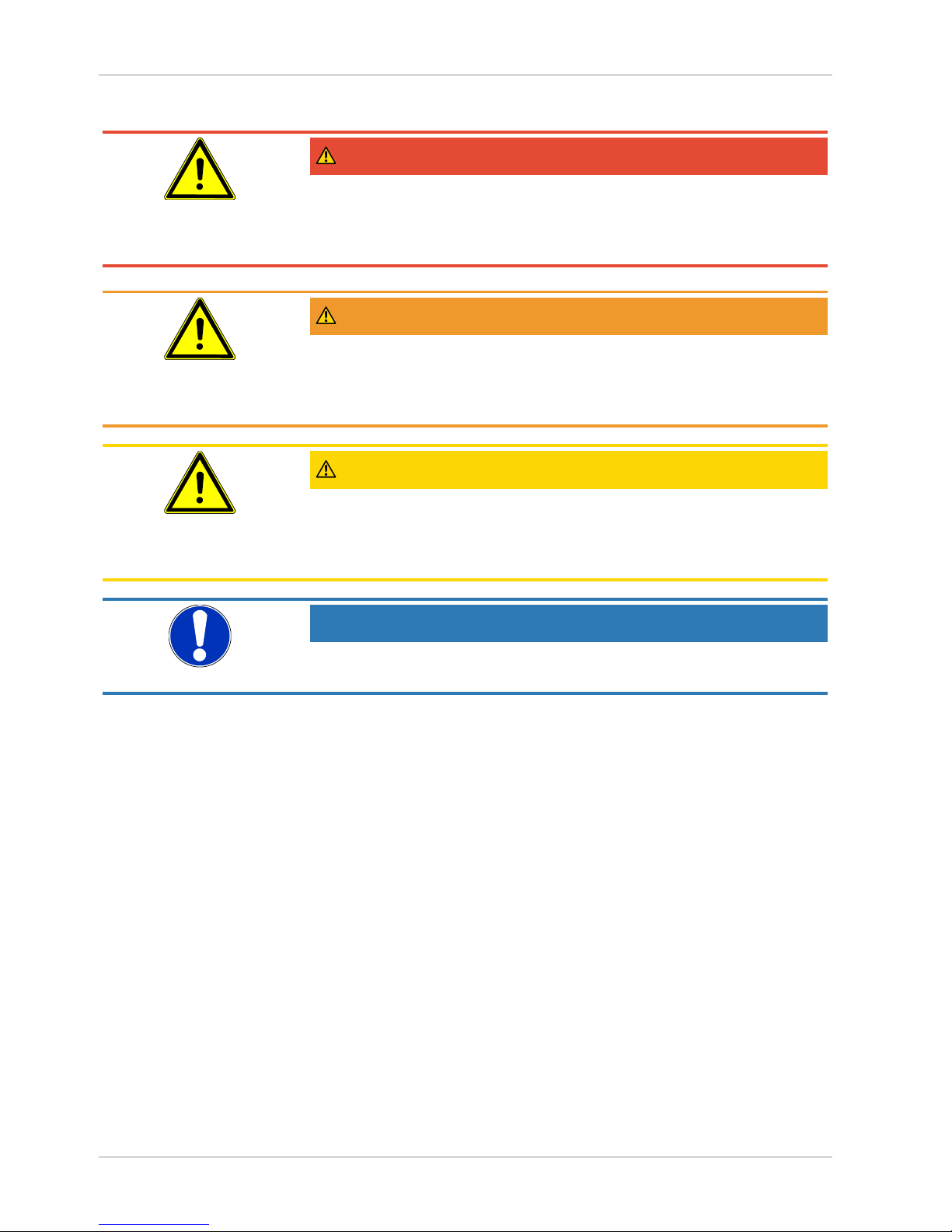
DANGER
Type and source of danger
This indicates a direct dangerous situation that could lead to death or serious
injury (highest danger level).
a) Avoid danger by observing the valid safety regulations.
WARNING
Type and source of danger
This indicates a potentially dangerous situation that could lead to death or serious injury (medium danger level).
a) Avoid danger by observing the valid safety regulations.
CAUTION
Type and source of danger
This indicates a potentially dangerous situation that could lead to slight or serious injury, damage or environmental pollution (low danger level).
a) Avoid danger by observing the valid safety regulations.
NOTICE
Note / advice
This indicates useful information of advice for efficient and smooth operation.
Page 7

FISCHER Mess- und Regeltechnik GmbH Product and functional description | 2
BA_EN_MA15_ATEX 7 / 36
2 Product and functional description
2.1 Delivery scope
• Diaphragm manometer MA15
• Operating Manual
2.2 Product summary
Manometer casing
Scale
Flange
Connecting shanks
Ground connection
Contact element
Contact element
MA15F ... 0A MA15F ... 1B/2C/2D
Fig.1: Product summary
Manometer casing
The following options are available for the manometer casing:
• Bayonet ring housing NG100 or NG160
• Safety casing NG100 or NG160
with unbreakable rear wall and blow-out opening acc. to DIN EN 837
Process connection
Please see the order code for precise details about the process connection options (flange and connection pin).
G¼B G⅜B G½B ¼-18 NPT ½-14 NPT
M20 x 1.5
Fig.2: Process connection
Page 8
2 | Product and functional description FISCHER Mess- und Regeltechnik GmbH
8 / 36 BA_EN_MA15_ATEX
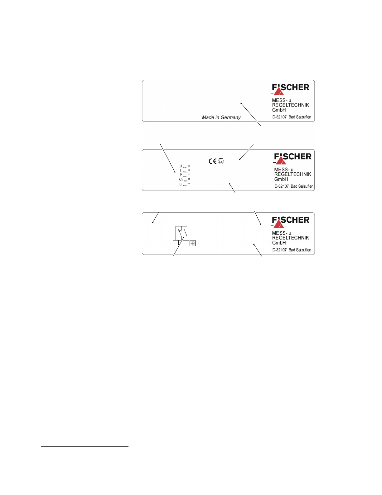
2.2.1 Type plate
This type plate serves as an example of the information that is stated. The data
shown is purely fictive, but does correspond to the actual conditions. For more
information, please see the order code at the end of these instructions.
Article no.
Measuring range
P max
Prod. - No.
Install vertically
MA15F83HV87L011B
0...400 mbar
40 bar
587016.01.002
Serial number
Only connect to certified intrinsically safe circuits.
max. voltage:
Max. power:
Max. capacity:
max. output:
Max. inductivity
30 V
200 mA
800 mW
60 pF
4 µH
Tu 60°C
T medium in the device max. 85°C
Reference no.: 8000389448
0044 TÜV NORD 2014/34/EU
max.
II 2G c 95°C IP65
Limit data
Supply circuit
ATEX code
Notified office
Article no.
Measuring range
P max
Prod. - No.
MA15F83HV87L0100
0...400 mbar
40 bar
587016.01.002
Serial number
Contact function
KE21M210AH2
Made in Germany
4 1 2
Zero position
Switching output
U max :
250V AC/DC
I max :
1A ΩLoad
P max :
30W750VA
Built-in contacts
Built-in contacts
Technical data
Fig.3: Type plates with and without contacts
2.3 Intended use
The units may only be used for the purpose stipulated by the manufacturer.
The units serve to measure over-pressure and under-pressure in industrial ap-
plications in areas at risk of explosion acc. to directive 2014/34/EU.
The optional installed switch elements are low-action contacts, mechanical
magnetic spring contacts, inductive proximity switches in a slotted design or capacitive rotation angle encoder.
(1)
If the set limit values are exceeded, the out-
put power circuits are opened or closed.
The corresponding setup regulations are to be considered for each application
case.
(1)
Please see the information in the order code.
Page 9
FISCHER Mess- und Regeltechnik GmbH Product and functional description | 2
BA_EN_MA15_ATEX 9 / 36
2.4 Function diagram
1
2
3
4
Fig.4: Function diagram
1 Motion train 2 Connecting rod
3 Flange 4 Diaphragm
2.5 Design and mode of operation
The measuring element, the concentric corrugated diaphragm, is clamped
between two flanges and the medium is applied on one side.
The diaphragm bulges elastically from its normal position as a result of the applied pressure. The linear movement is proportional to the applied pressure. A
rod assembly on the side of the diaphragm that faces away from the medium
captures the expansion movement and transfers it to the indicator.
The measurement display is shown on a 270 W° scale.
Page 10
3 | Assembly FISCHER Mess- und Regeltechnik GmbH
10 / 36 BA_EN_MA15_ATEX
3 Assembly
3.1 Generalities
The instrument may only be installed and commissioned by specialized personnel familiar with the installation, commissioning and operation of this product.
Specialized personnel are persons who can assess the work they have been
assigned and recognize potential dangers by virtue of their specialized training,
their skills and experience and their knowledge of the pertinent standards.
WARNING
Mounting pressure transmitters
During assembly, observe the respective national and international guidelines
and safety regulations.
Only mount the unit to systems that are depressurized. Only ever operate the
unit within the permitted measuring range or below the maximum overload.
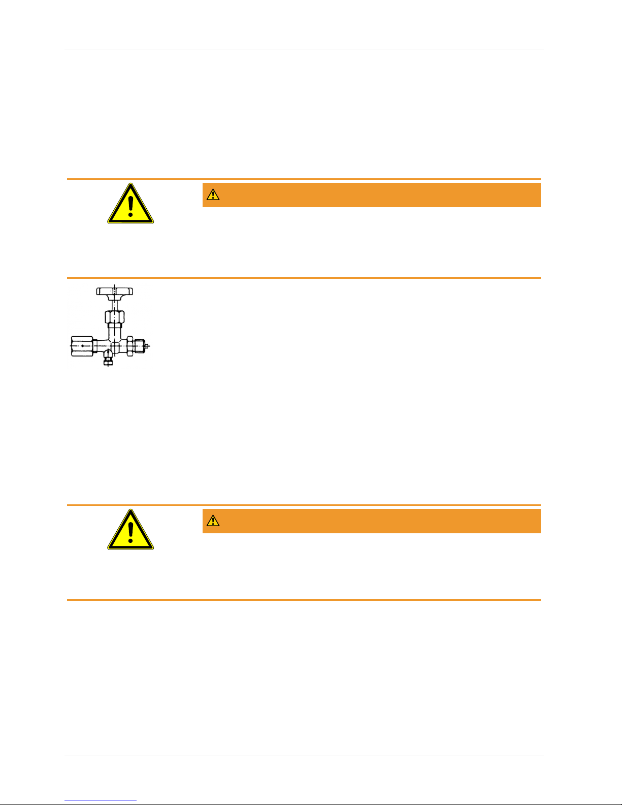
Fig.5: Shutoff valve.
The device is set ex-works for vertical installation, however any installation position is possible.
To guarantee safe working conditions during installation and maintenance, suitable stop valves must be fitted in the system (see accessories). By means of
the manometer shutoff, the unit
• Can be depressurized or taken out of operation.
• Be disconnected from the power supply within the applicable system for repairs or inspections.
3.2 Process connection
• By authorized and qualified specialized personnel only.
• The pipes need to be depressurized when the instrument is being connected.
• Appropriate steps must be taken to protect the device from pressure surges.
• Check that the device is suitable for the medium being measured.
• Maximum pressures must be observed (cf. Tech. data)
WARNING
Earth connection via the system earth
During assembly, ensure that the earth connection between the unit and the
system earth is ensured. The connection to the system earth is realised via the
process connection. Therefore, never use an insulated Teflon tape or similar.
Design the process connection acc. to EN 837 and use a suitable flat seal.
3.2.1 Measuring lines that need to be connected
The following points need to be observed when connecting the pressure line:
• To ensure there is no influence on the measured values, severe bends and
coils in the wire should be avoided.
• To prevent deposits, there should be a continuous incline or drop of at least
8%.
• When measuring steam pressure, a water bag-forming loop must be
provided due to the temperature (see accessories).
Page 11

FISCHER Mess- und Regeltechnik GmbH Assembly | 3
BA_EN_MA15_ATEX 11 / 36
Round shape U-shape
G½
ca. 180
Ø20
56
155
ca. 200
G½
G½
ca. 275
ca. 130
Ø20
Ø56
G½
AF27
Manometer connection
Connection spigot
according to
DIN EN 837-1
Fig.6: Siphon MZ1###
• The transmitter must be positioned below the measuring point for liquid
measurements. Vent the pressure line before commissioning.
• The transmitter must be positioned above the measuring point for gas
measurements.
3.2.2 Pressure surge absorption
Pulsating pressure on the system side can lead to functional problems. We recommend installing a damping element in the pressure connection lines as a
protective measure.
a) Capillary throttle
Manometer connection
SW27 AF27
Connection spigot
according to DIN EN 837-1
305
110
G½
G½
Ø88
Ø4
Fig.7: Capillary throttle MZ400#
Page 12

3 | Assembly FISCHER Mess- und Regeltechnik GmbH
12 / 36 BA_EN_MA15_ATEX
b) Settable damping reactor
In operating mode, the damping throttle must be set so that the output signal
follows the pressure changes with a delay.
G½
G½
20
66
19
AF27
Setting screw
Connection spigot
according to DIN EN 837-1
Manometer connection
Fig.8: Damping reactor MZ410#
3.3 Electrical connections
3.3.1 General information
Only units with installed contacts or a rotation angle transducer are connected
to the power supply.
• By authorized and qualified specialized personnel only.
• When connecting the unit, the national and international electro-technical
regulations must be observed.
• The electrical connection is usually realised via a cable socket mounted to
the side.
• Disconnect the system from the mains, before electrically connecting the
device.
• Please see the type plate for the connection assignment.
WARNING
Operation in areas at risk of explosion
If operated in explosive areas, the electrical data of the unit and the valid local
regulations and guidelines for the installation and operation of electrical systems
in explosive areas must be observed (e.g. DIN EN 60079-14)
Ground connection
The outer ground connection must always be connected to the protective potential equalisation or a similar local potential equalisation. The connection is suitable for connecting fine-wire conductors up to 4 mm2 or single-wire conductors
up to 6 mm2.
3.3.2 Limit switch in accordance with data sheet KE
For more technical information about the contact types and connection options,
please see the data sheet KE. You can request the data sheet on request or via
our webserver www.fischermesstechnik.de.
Page 13

FISCHER Mess- und Regeltechnik GmbH Assembly | 3
BA_EN_MA15_ATEX 13 / 36
3.3.3 Rotation angle transducer acc. to data sheet KE09
For more technical information about the rotation angle transducer, please see
the data sheet KE09. You can request the data sheet on request or via our webserver www.fischermesstechnik.de.
3.4 Use in areas at risk of explosion
3.4.1 Differential pressure transmitter without contact element
MA15 … 0A
II 2G Ex h IIC T4 Gb
II 2D Ex h IIIC T95°C Db
Explosive areas Zone 1 and 2, and 21 and 22, risk from gases and dry dust.
Allowed temperatures:
• The maximum surface temperature 95 °C was determined under the following conditions without dust accumulation and safety factor.
• Allowed ambient temperature: -20°C to +60°C.
• Allowed medium temperature in the differential measurement unit < 85°C.
WARNING
Compression heat
With gaseous mediums, the instrument temperature can increase due to compression heat. In such cases, the pressure change speed must be limited or reduced to the allow measuring substance temperature.
NOTICE!For a differential pressure change between 10% and 90% of the
measuring range and a pulse frequency < 0.06 Hz, the temperature increase is <10K.
To avoid additional heating, the instruments may not be exposed to direct sunlight during operation!
The standards EN60079-0, EN 60079-31, EN ISO 80079-36 and EN ISO
80079-37 apply for the non-electrical part of the devices in terms of explosion
protection. The applicable requirements of these standards are satisfied.
The documents for the mechanical part were filed with notified office NB0044
(TÜV-Nord-Cert) under the file number 8000389448.
Page 14

3 | Assembly FISCHER Mess- und Regeltechnik GmbH
14 / 36 BA_EN_MA15_ATEX
3.4.2 Differential pressure transmitter with magnetic spring contacts
MA15 … 1B
II 2G Ex h IIC T4 Gb
Simple electric operating equipment acc. to EN60079-11 sec: 5.7 in explosive
areas Zone 1 and 2.
Contact element: KE ## M ## 0B4H2
Allowed temperatures:
• The maximum surface temperature 95 °C was determined under the following conditions without dust accumulation and safety factor.
• Allowed ambient temperature: -20°C to +60°C.
• Allowed medium temperature in the differential measurement unit < 85°C.
WARNING
Compression heat
With gaseous mediums, the instrument temperature can increase due to compression heat. In such cases, the pressure change speed must be limited or reduced to the allow measuring substance temperature.
NOTICE!For a differential pressure change between 10% and 90% of the
measuring range and a pulse frequency < 0.06 Hz, the temperature increase is <10K.
To avoid additional heating, the instruments may not be exposed to direct sunlight during operation!
The standards EN60079-0, EN ISO 80079-36 and EN ISO 80079-37 apply for
the non-electrical part of the devices in terms of explosion protection. The applicable requirements of these standards are satisfied.
As a simple electrical operating unit, the installed electrical switch contacts fulfil
the requirements of the standard EN60079-14 Par. 3.5.2. The devices are not
labelled with respect to the electrical part.
The documents for the mechanical part were filed with notified office NB0044
(TÜV-Nord-Cert) under the file number 8000389448.
Intrinsically safe power circuits
For use in areas at risk of explosion, instruments must be connected to certified,
intrinsically safe electricity circuits.
Max. voltage U
max
30 V
Max. current I
max
200 mA
Max. power P
max
800 mW
Max. inner capacity C
i max
60 pF
Max. inner inductivity L
i max
4 µH
Recommend circuit breakers see accessories
Page 15

FISCHER Mess- und Regeltechnik GmbH Assembly | 3
BA_EN_MA15_ATEX 15 / 36
3.4.3 Differential pressure transmitter with inductive contacts
MA15 … 1C
II 2G Ex h IIC T4 Gb
II 2D Ex h IIIC T95°C Db
Explosive areas Zone 1 and 2, and 21 and 22, risk from gases and dry dust.
Contact element: KE ## I ## 0C0H2
Allowed temperatures:
• The maximum surface temperature 95 °C was determined under the following conditions without dust accumulation and safety factor.
• Allowed ambient temperature: -20°C to +60°C.
• Allowed medium temperature in the differential measurement unit < 85°C.
WARNING
Compression heat
With gaseous mediums, the instrument temperature can increase due to compression heat. In such cases, the pressure change speed must be limited or reduced to the allow measuring substance temperature.
NOTICE!For a differential pressure change between 10% and 90% of the
measuring range and a pulse frequency < 0.06 Hz, the temperature increase is <10K.
To avoid additional heating, the instruments may not be exposed to direct sunlight during operation!
The standards EN60079-0, EN 60079-31, EN ISO 80079-36 and EN ISO
80079-37 apply for the non-electrical part of the devices in terms of explosion
protection. The applicable requirements of these standards are satisfied.
The installed inductive proximity switches of the type SJ2-N (106575) are EC
type-tested with the certificate PTB 99 ATEX 2219 X. The type of the installed
proximity switch is stated on the type plate. The manufacturer is Pepperl+Fuchs
GmbH. For more information about proximity switches, please visit the website
https://www.pepperl-fuchs.com.
The documents for the mechanical part were filed with notified office NB0044
(TÜV-Nord-Cert) under the file number 8000389448.
Intrinsically safe power circuits
For use in areas at risk of explosion, instruments must be connected to certified,
intrinsically safe electricity circuits.
Max. voltage U
max
16 V
Max. current I
max
25 mA
Max. power P
max
64 mW
Max. inner capacity C
i max
30 nF
Max. inner inductivity L
i max
100 µH
Recommend circuit breakers see accessories
Page 16

3 | Assembly FISCHER Mess- und Regeltechnik GmbH
16 / 36 BA_EN_MA15_ATEX
3.4.4 Differential pressure transmitter with rotation angle transducer
MA15 … 2D
II 2G Ex h IIC T4 Gb
Explosive areas Zone 1 and 2, risk from gases.
Rotation angle transducer: KE0905#9
Allowed temperatures:
• The maximum surface temperature 95 °C was determined under the following conditions without dust accumulation and safety factor.
• Allowed ambient temperature: -20°C to +60°C.
• Allowed medium temperature in the differential measurement unit < 85°C.
WARNING
Compression heat
With gaseous mediums, the instrument temperature can increase due to compression heat. In such cases, the pressure change speed must be limited or reduced to the allow measuring substance temperature.
NOTICE!For a differential pressure change between 10% and 90% of the
measuring range and a pulse frequency < 0.06 Hz, the temperature increase is <10K.
To avoid additional heating, the instruments may not be exposed to direct sunlight during operation!
The standards EN60079-0, EN ISO 80079-36 and EN ISO 80079-37 apply for
the non-electrical part of the devices in terms of explosion protection. The applicable requirements of these standards are satisfied.
The installed capacitive rotation angle measuring transducer of the type KINAX
3W2 are EC type-tested with the certificate ZELM 10 ATEX 0427 X. The type of
the installed rotation angle transducer is stated on the type plate. The manufacturer is Camille Bauer Metrawatt AG. For more information about the rotation
angle transducer, please visit the website http://www.camillebauer.com.
The documents for the mechanical part were filed with notified office NB0044
(TÜV-Nord-Cert) under the file number 8000389448.
Intrinsically safe power circuits
For use in areas at risk of explosion, instruments must be connected to certified,
intrinsically safe electricity circuits.
Max. voltage U
max
30 V
Max. current I
max
160 mA
Max. power P
max
1 mW
Max. inner capacity C
i max
10 nF
Max. inner inductivity L
i max
0 µH
Recommend circuit breakers see accessories
Page 17

FISCHER Mess- und Regeltechnik GmbH Commissioning | 4
BA_EN_MA15_ATEX 17 / 36
4 Commissioning
4.1 General
All electrical supply, operating and measuring lines, and the pressure connections must have been correctly installed before commissioning. All supply lines
are arranged so that there are no mechanical forces acting on the device.
Check that the pressure connections do not leak before commissioning.
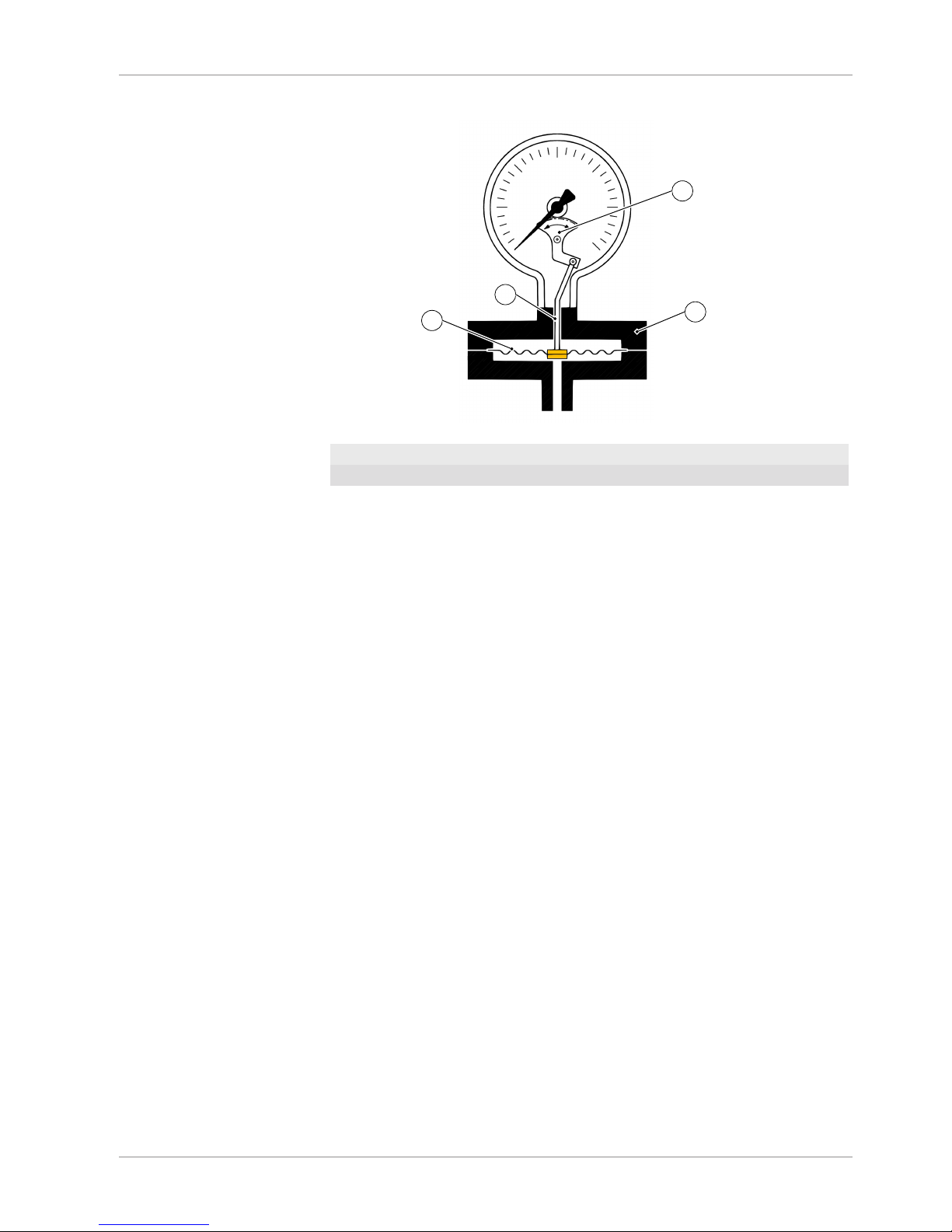
4.2 Zero point correction
The pressure measuring units are set in the factory before delivery so that they
do not usually need to be adjusted at the assembly site.
The zero-point may need to be corrected for some units on site (see order
code).
Units with setting screw
Venting valve
Venting valve
Zero-point correction screw
Fig.9: Zero point correction
1. Depressurize the measuring line or only exert the existing static system
pressure.
2. Open the venting valve as shown in the illustration and carefully remove the
entire valve plug from the casing.
3. Adjust the measurement value pointer using zero point correction screw to
the scale zero point.
4. Refit the valve plug into the casing.
5. Close the venting valve.
Unit with micro adjustment indicator
Micro adjustment indicators can only be used in units without a fluid filling.
Fig.10: Micro adjustment indicator
1. Open the casing by releasing the bayonet ring.
2. Set the indicator to zero with a screwdriver.
3. Close the casing.
Page 18

4 | Commissioning FISCHER Mess- und Regeltechnik GmbH
18 / 36 BA_EN_MA15_ATEX
4.3 Switch point setting
There is an adjustment lock attached to the front pane of the measuring unit on
units with installed limit signal encoders. Using the detachable adjustment key,
the contacts attached to the target indicators can be set to any point along the
scale.
To facilitate switching precision and the service life of the mechanical measuring system, the switching points should lie between 10% and 90% of the measuring range.
Set-point display
Drive pin
Drive arm
Adjustment key
Adjusting lock
Fig.11: Contact element
1. Place the adjustment key on the axle of the adjusting lock
2. Press axle inwards until the drive arm reaches behind the setting pin of the
target value indicator.
3. Set the target value indicator to the required switch point by turning the key.
4. Relieve the axle, remove the adjustment key
Contact function
Function 1: Close contacts for increasing display in clockwise direction.
Function 2: Open contacts for increasing display in clockwise direction.
Contact assignment:
Up to three contacts are available depending on the unit version.
1. Contact left target indicator
2. Contact middle target indicator
3. Contact right target indicator
4.4 Units with a rotation angle transducer
The capacitive rotation angle transducer records the angle setting of the indicator in a contact-free manner and changes this into an measurement that is proportional to the AC current signal. The device is configured in the factory before
delivery and cannot be reset on site.
Page 19

FISCHER Mess- und Regeltechnik GmbH Servicing | 5
BA_EN_MA15_ATEX 19 / 36
5 Servicing
5.1 Maintenance
To ensure reliable operation and a long service life, we recommend carrying out
the following test on a regular basis:
• Check the reading.
• Checking the switch function in connection with the downstream components.
• Checking the pressure lines for leaks.
• Checking the electrical connections (terminal connection of the cable).
The precise test cycles and operating and ambient conditions need to be adjusted. If several components of the unit interact, all operating instructions of the
other units also need to be observed.
WARNING
Dust deposits
The device must be cleaned with a damp cloth a regular intervals to prevent
heat build-up. Cleaning intervals depend on the amount of local dust.
5.2 Transport
The measuring device must be protected against impacts. It should be transported in the original packaging or a suitable transport container.
5.3 Service
All defective or faulty devices should be sent directly to our repair department.
Please coordinate all shipments with our sales department.
WARNING
Process media residues
Process media residues in and ondismantled devices can be a hazard to
people, animals and the environment. Take adequate preventive measures. If
required, the devices must be cleaned thoroughly.
Return the device in the original packaging or a suitable transport container.
5.4 accessories
• Siphons MZ1###
• Capillary throttle coil MZ400#
• Settable damping reactor MZ410#
• Manometer shutoff valves MZ5###, MZ6###
Please see here the data sheet MZ measuring devices accessories. Here you
will find more detailed information about the technical data and the order codes
of the accessory parts MZ.
You can request the data sheet on request or via our webserver www.fischer-
messtechnik.de.
Page 20

5 | Servicing FISCHER Mess- und Regeltechnik GmbH
20 / 36 BA_EN_MA15_ATEX
5.5 Disposal
WARNING
Incorrect disposal may pose a risk to the environment.
Please help to protect the environment by always disposing of the work pieces
and packaging materials in compliance with the valid national waste and recycling guidelines or reuse them.
Page 21

FISCHER Mess- und Regeltechnik GmbH Technical Data | 6
BA_EN_MA15_ATEX 21 / 36
6 Technical Data
6.1 Standard version
The measuring variable is pressure and/or under-pressure in gaseous, liquid,
aggressive, highly viscous or soiled media.
The diaphragm manometer fulfils the requirements of the standard EN 837-3.
Measuring range
0 …16 mbar to 0 … 250mbar Flange diameter 160 mm
0 … 400 mbar bar to 0 … 25 bar Flange diameter 100 mm
-1 … 0 to -1 … 24 bar
Pressure load
Admissible overload 5x Scale upper value (max. 40 bar)
Idle load Scale upper value
Alternating load 0.9 x Scale upper value
Max. pressure (flange screw connec-
tion)
160 mm 10 bar
100 mm 40 bar
Process connection
Connecting shanks G½B, G¼B, G⅜B
¼-18 NPT, ½-14 NPT
M20 x 1.5
Connection flange DIN EN DN20, DN25, DN50 PN40
Connection flange ANSI 1ʺ, 2ʺ, 3ʺ 150 lbs, 300 lbs
open connection flange with loose col-
lare flange
*)
DN 50 PN40
*)
only for measuring ranges ≥400mbar
Accuracy class
1.6
2.5 Units with coated / cladded measuring system
Permissible temperature
Increase ambient temperature -20 °C … +60 °C
Media temperature ≤ 85 °C
Storage temperature -40 °C … +70 °C
Temperature influence
If there is a reference temperature difference of +20 °C on the measuring system:
≤ ±0.8 % /10 K of the respective scale upper value
Housing
Bayonet ring housing Ø 100 or 160 mm
Safety housing
Page 22

6 | Technical Data FISCHER Mess- und Regeltechnik GmbH
22 / 36 BA_EN_MA15_ATEX
Protection
IP66 acc. to EN 60529 / IEC 60529
Materials
Housing CrNi Steel 1.4404
Motion train CrNi steel 1.4301
Dial face and needle Aluminium (painted)
Inspection disk Safety laminated glass
Connecting port (contact with medium) CrNi-steel 1.4404 (AISI 316L)
Connection flange (contact with me-
dium)
CrNi-steel 1.4404 (AISI 316L)
Diaphragm (contact with medium)
- Measuring range ≤ 250 mbar CrNi steel 1.4571 (AISI 316T)
- Measuring ranges ≥ 400 mbarr NiCrCo alloy (DURATHERM®)
Seals (contact with medium) VITON
®
6.2 Options
Additional electrical attachments
Limit signal transmitters of the type KE and capacitive rotation angle transducer
of the type KE09 can be fitted into a housing enlarged by a corresponding bayonet ring. The electrical connection is usually realised via a cable connection
socket mounted to the side of the casing.
Please refer to the data sheets KE and KE09 for technical data. You can receive the data sheet on request or download them from our webserver
www.fischermesstechnik.de.
Fluid charging
The housing can be filled with glycerine if the casing is to operate under aggravated operating conditions such as vibrations and extreme pressure fluctuations,
or in order to avoid condensate formation if used outdoors.
• Silicone oil is used in units with switch contacts.
• Paraffin oil is used in units with inductive proximity switches.
• Filling is not possible in units with a capacitive rotation angle transducer.
Needle
• Marker indicator
Settable indicator for marking the limit value in the disk.
• Drag indicator
The drag indicator is 'dragged' by the measured value indicator. As there is
no fixed connection between the two needles, one-off maximum values are
stored. The trailing needle can be reset using an adjusting dial in the window.
Page 23

FISCHER Mess- und Regeltechnik GmbH Technical Data | 6
BA_EN_MA15_ATEX 23 / 36
Measuring system
• O2applications 'Oil and grease'
In compliance with the requirements of the Chemical Professional Association, all parts that come into contact with the medium are cleaned (see order code filling fluids)
• PTFE cladding and/or PFA coating of the measuring system
In the case of highly aggressive media, all parts that come into contact with
the medium are coated with a protective sheath of PFA or PTFE. A FEP
covered O-Ring made of FKM is used for the flange seal. A suitable seal
needs to be used on the system side to seal the cladded units.
• Material
Optionally, the measuring system incl. the process connection is also made
of HastelloyC.
Zero point correction
• with a setting screw
• with a micro adjustment indicator
6.3 Dimensional drawings
All dimensions in mm unless otherwise stated
6.3.1 Model without contacts
B
NG
b1
h
Ød1
Fig.12: Dimension drawing MA15F without contacts
Housing NG B h b1 Ød1
Bayonet ring housing 100 53 130 19 100
160 53 160 19 157
Safety housing 100 63 130 26 100
160 65 160 26 157
Page 24

6 | Technical Data FISCHER Mess- und Regeltechnik GmbH
24 / 36 BA_EN_MA15_ATEX
6.3.2 Model with contacts
NG
B
h
Ød1
b1
e
Fig.13: Dimension drawing MA15F with contacts
Housing NG B h b1 Ød1 e
Bayonet ring housing 100 100 130 19 100 90
160 100 160 19 157 120
Safety housing 100 109 130 26 100 90
160 109 160 26 157 120
6.3.3 Process connection
6.3.3.1 Version with collar flange
The dimensions stated apply for all housing models NG100 and NG160.
h
h1
DN 50
Ø104
Ø165
Ø125
Hole circle (LK)
NG
Fig.14: Collar flange
Measuring range ≥ 400
mbar
DN PN NG h h1 LK
No. Borehole
50 40 100 94 91 4 18
160 124 121 4 18
Page 25

FISCHER Mess- und Regeltechnik GmbH Technical Data | 6
BA_EN_MA15_ATEX 25 / 36
6.3.3.2 Version with DIN connection flange
The dimensions stated apply for all housing models NG100 and NG160.
h
DN
Ød2
LK
ØD
NG
Fig.15: Connection flange
Measuring range ≤ 400
mbar
DN PN ØD Ød2 h LK
Ø No. Thread
20 40 157 58 111 75 4 M12
25 40 157 68 110 85 4 M12
50 40 165 102 108 125 4 M16
Measuring range ≥ 0.6
bar
20 40 105 58 106 75 4 M12
25 40 115 68 103 85 4 M12
50 40 165 102 108 125 4 M16
6.3.3.3 Version with ANSI connection flange
Dimension drawing, see Version with DIN connection flange [}25]. The dimensions stated apply for all housing models NG100 and NG160.
Measuring range ≤ 400
mbar
ØD Ød2 h LK
Ø No. Thread
1ʺ 150 lbs 157 50.8 118 79.2 4 ½-13 UNC
1ʺ 300 lbs 157 50.8 120 88.9 4 ⅝-11 UNC
2ʺ 150 lbs 157 91.9 123 120.7 4 ⅝-11 UNC
3ʺ 150 lbs 165 92.1 114 127 8 ⅝-11 UNC
Measuring range ≥ 0.6
bar
1ʺ 150 lbs 108 50.8 118 79.2 4 ½-13 UNC
1ʺ 300 lbs 123 50.8 124 88.9 4 ⅝-11 UNC
2ʺ 150 lbs 152 91.9 107 120.7 4 ⅝-11 UNC
3ʺ 150 lbs 190.5 127 119 152.4 4 Ø19.1
Page 26

6 | Technical Data FISCHER Mess- und Regeltechnik GmbH
26 / 36 BA_EN_MA15_ATEX
6.3.3.4 Connecting shanks
DIN 837 ANSI B1.20.1
G
d1
d2
l1
l2
Centring pin
l1
G
NPT
AF
Fig.16: Connecting shanks
G (Thread) d1 d2 l1 l2 SW
G¼B 5 9.5 13 2 19
G⅜B 5.5 13 16 3 22
G½B 6 17.5 20 3 22
M20 x 1.5 6 17.5 20 3 22
¼-18 NPT 15 19
½-14 NPT 19 22
Page 27

FISCHER Mess- und Regeltechnik GmbH Order Codes | 7
BA_EN_MA15_ATEX 27 / 36
7 Order Codes
Process connection
Rated pressure of the
measuring system
Design of the measuring system
Housing
Special functions
M A 1 5
Type
Measuring range
F
1 2 5 6 7 8 9 10 11 123 4Code no.
Fluid charging
ATEX model
[2.3] Measuring range
55 0 … 16 mbar
56 0 … 25 mbar
57 0 … 40 mbar
58 0 … 60 mbar
59 0 … 100 mbar
60 0 … 160 mbar
82 0 … 250 mbar
83 0 … 400 mbar
01 0 … 0.6 bar
02 0 … 1 bar
03 0 … 1.6 bar
04 0 … 2.5 bar
05 0 … 4 bar
06 0 … 6 bar
07 0 … 10 bar
08 0 … 16 bar
09 0 … 25 bar
31 -1 … 0 bar
32 -1 … 0.6 bar
33 -1 … 1.5 bar
34 -1 … 3 bar
35 -1 … 5 bar
36 -1 … 9 bar
37 -1 … 15 bar
28 -1 … 24 bar
Page 28

7 | Order Codes FISCHER Mess- und Regeltechnik GmbH
28 / 36 BA_EN_MA15_ATEX
[4] Rated pressure of the measuring system
E 10 bar (Measuring ranges ≤ 250 mbar)
H 40 bar (Measuring ranges ≥ 400 mbar)
[5] Design of the measuring system
V CrNi Steel 1.4404
S CrNi steel 1.4404 with diaphragm in Hastelloy C
T CrNi steel 1.4404 with PFA coating
P CrNi steel 1.4404 with PTFE coating
[6.7] Process connection
85 Connection shanks with external thread G¼B acc. to DIN EN 837
86 Connection shanks with external thread G⅜B acc. to DIN EN 837
87 Connection shanks with external thread G½B acc. to DIN EN 837
88 Connecting port G½ with outer thread ¼-18 NPT
89 Connecting port G½ with outer thread ½-14 NPT
S2 Connection shanks with external thread M20 x 1.5 acc. to DIN EN
3852
FL open flange with collar attachment flange DN50 PN40
*)
F1 Connection flange DN20, PN40
F2 Connection flange DN25, PN40
F5 Connection flange DN50, PN40
D3 ANSI flange 1ʺ 150 lbs
D8 ANSI flange 1ʺ 300 lbs
D6 ANSI flange 2ʺ 150 lbs
D5 ANSI flange 3ʺ 150 lbs
*)
only for measuring ranges from 400 mbar
[8] Housing
L Bayonet ring housing NG100
C Bayonet ring housing NG160
0 Safety housing NG100
P Safety housing NG160
[9] Fluid charging
0 Without fluid filling
1 Glycerine Unit without contacts
4 Paraffin Unit with inductive contacts
5 Silicone oil
Please note that units can only be filled with fluid from a measuring range of
100 mbar. Units with an installed rotation angle transducer cannot be filled.
Page 29

FISCHER Mess- und Regeltechnik GmbH Order Codes | 7
BA_EN_MA15_ATEX 29 / 36
[10] Special functions
1 Zero-point correction with setting
screw
2 Zero-point correction micro adjust-
ment indicator
3 Zero-point correction with setting
screw
Adjustable marker needle
4 Zero-point correction with setting
screw
Resettable drag needle
♣)
5 Zero-point correction micro adjust-
ment indicator
Adjustable marker needle
6 Zero-point correction micro adjust-
ment indicator
Resettable drag needle
♣)
♣)
only for measuring ranges from 60 mbar
[11.12] ATEX
0A Non-electrical unit
(without switch contacts)
II 2G Ex h IIC T4 Gb
II 2D Ex h IIICT95°C Db
1B Unit with magnetic spring contacts
KE##M##0B4H2
Simple electrical operating equipment acc.
to DIN EN 60079-11
II 2G Ex h IIC T4 Gb
1C Unit with inductive contacts KE##I##0C0H2 II 2G Ex h IIC T4 Gb
II 2D Ex h IIIC T95°C Db
2D Unit with capacitive rotation angle trans-
ducer KE0905#9
II 2G Ex h IIC T4 Gb
Page 30

8 | Attachments FISCHER Mess- und Regeltechnik GmbH
30 / 36 BA_EN_MA15_ATEX
8 Attachments
8.1 EU Declarations of conformity
Fig.17: CE_DE_MA15F_1B_Page1
Page 31

FISCHER Mess- und Regeltechnik GmbH Attachments | 8
BA_EN_MA15_ATEX 31 / 36
Fig.18: CE_DE_MA15F_1B_Page2
Page 32

8 | Attachments FISCHER Mess- und Regeltechnik GmbH
32 / 36 BA_EN_MA15_ATEX
Fig.19: CE_DE_MA15F_1C_Page1
Page 33

FISCHER Mess- und Regeltechnik GmbH Attachments | 8
BA_EN_MA15_ATEX 33 / 36
Fig.20: CE_DE_MA15F_1C_Page2
Page 34

8 | Attachments FISCHER Mess- und Regeltechnik GmbH
34 / 36 BA_EN_MA15_ATEX
Fig.21: CE_DE_MA15F_2D_Page1
Page 35

FISCHER Mess- und Regeltechnik GmbH Attachments | 8
BA_EN_MA15_ATEX 35 / 36
Fig.22: CE_DE_MA15F_2D_Page2
Page 36

8 | Attachments FISCHER Mess- und Regeltechnik GmbH
36 / 36 BA_EN_MA15_ATEX
Fig.23: CE_DE_MA15F_0A
 Loading...