

Page 1
DELTASCOPE® FMP10
ISOSCOPE® FMP10
DUALSCOPE® FMP20
Guidelines
Coating Thickness Material TestingMicrohardnessMaterial Analysis
Page 2

Page 3
Please study the safety information in the operator’s
manual as well.
Observe the warnings and hints in th e opera tor’s manual
in order to avoid injury and damage to the instrument!
Table of Contents
1 Notes . . . . . . . . . . . . . . . . . . . . . . . . . . . . . . . . . . . . . . . . . . . 1
2 Areas of Application . . . . . . . . . . . . . . . . . . . . . . . . . . . . 2
3 Description of the Instrument . . . . . . . . . . . . . . . . . . . 3
3.1 LCD Display . . . . . . . . . . . . . . . . . . . . . . . . . . . . . . . . . . 4
3.2 Control Panel Key Functions . . . . . . . . . . . . . . . . . . . . 5
4 Probe handling . . . . . . . . . . . . . . . . . . . . . . . . . . . . . . . . . 6
5 The Path to the First Measurement . . . . . . . . . . . . . 6
6 System Setup . . . . . . . . . . . . . . . . . . . . . . . . . . . . . . . . . . 7
6.1 Install the batteries/rechargeable batteries . . . . . . . . . . 7
6.2 Probe connection . . . . . . . . . . . . . . . . . . . . . . . . . . . . . . 8
6.3 Instrument On/Off . . . . . . . . . . . . . . . . . . . . . . . . . . . . . 9
7 Adjusting Instrument and Probe . . . . . . . . . . . . . . . 11
7.1 Assigning a New Probe . . . . . . . . . . . . . . . . . . . . . . . . 11
7.2 Normalization . . . . . . . . . . . . . . . . . . . . . . . . . . . . . . . . 12
7.3 Corrective Calibration . . . . . . . . . . . . . . . . . . . . . . . . . 13
7.4 Reference Measurements . . . . . . . . . . . . . . . . . . . . . . 16
8 Measuring . . . . . . . . . . . . . . . . . . . . . . . . . . . . . . . . . . . . . 16
9 Service Functions . . . . . . . . . . . . . . . . . . . . . . . . . . . . . 17
Order number: Version 1.0
901-095 08/08
Page 4
1Notes
This brief guide offers a first, brief overview of your instrument's operation and
provides quick steps towards your first measurement results. An extensive operator's manual can be found on the CD-ROM that is supplied with the instrument.
The following symbols are used in this brief guide.
Indicates safety information referring to danger for persons and warnings regarding damage to the measuring
instrument or to accessories.
Indicates particularly important information and hints.
Indicates a reference to a page or chapter in this guide.
Notes
Brief Guide FMP10 / FMP20 Page 1
Page 5

2 Areas of Application
The instrument is used for coating thickness measurements.
The following table lists the measurement methods that are used in the various
FMP instruments.
Instrument Area of application
Areas of Application
DELTASCOPE
ISO-
SCOPE
Determination of the thickness of non-magnetic
coatings on steel or iron. E.g, chrome, copper, zinc
as well as paint, lacquer, enamel or plastic coatings on steel or iron.
Determination of the thickness of electrically nonconducting, non-magnetic coatings on non-ferromagnetic electrically conducting base materials.
Paint, lacquer or plastic coatings on, for example,
aluminum, copper, zinc, etc. as well as anodized
coatings on aluminum.
Determination of the thickness of non-magnetic
coatings on steel or iron. E.g, chrome, copper, zinc
as well as paint, lacquer, enamel or plastic coatings.
Measurement method /
Probe type
Magnetic Induction Method
According to DIN EN ISO
2178.
Probe: e.g., FGAB1.3
Amplitude-Sensitive Eddy
Current Method According to
DIN EN ISO 2360.
Probe: e.g., FTA3.3
Magnetic Induction Method
According to DIN EN ISO
2178.
Probe: e.g., FD10
DUALSCOPE
Determination of the thickness of electrically nonconducting, non-magnetic coatings on non-ferromagnetic electrically conducting base materials.
Paint, lacquer or plastic coatings on, for example,
aluminum, copper, zinc, etc. as well as anodized
coatings on aluminum.
Amplitude-Sensitive Eddy
Current Method According to
DIN EN ISO 2360.
Probe: e.g., FD10
The instrument has the capability of setting up up to 1000 readings to save.
Page 2 Brief Guide FMP10 / FMP20
Page 6
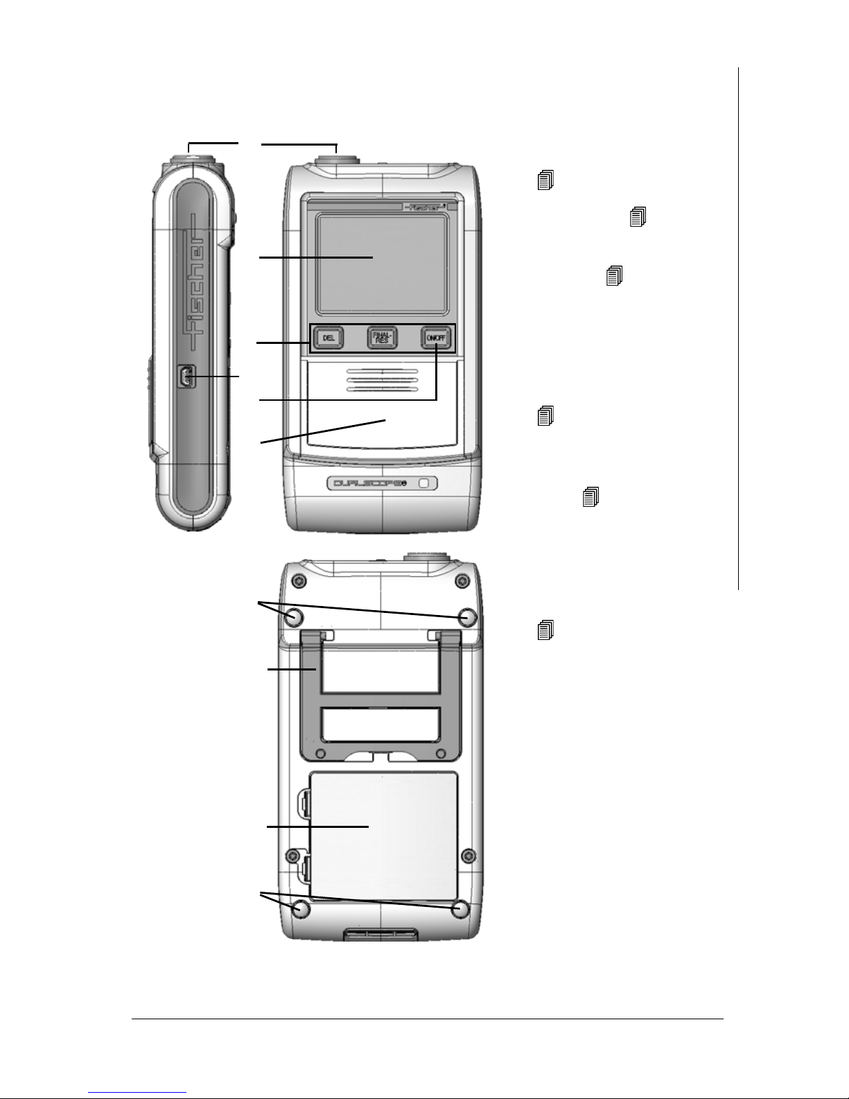
3 Description of the Instrument
1 Probe connector socket,
Page 8
2 LCD Display, Page 4
3 Keys for directly retrieving
functions, Page 5
4 USB port for connecting a
PC
5 ON/OFF key to turn the in-
strument on or off,
Page 9
6 Cover; additional function
keys can be found under the
cover, Page 5
7 Non-slip rubber supports
8 Foldable instrument stand
9 Battery compartment,
Page 7
1
2
3
4
5
6
7
8
9
7
Description of the Instrument
Fig. 3-1 Front and rear view of the instrument, connections
Brief Guide FMP10 / FMP20 Page 3
Page 7
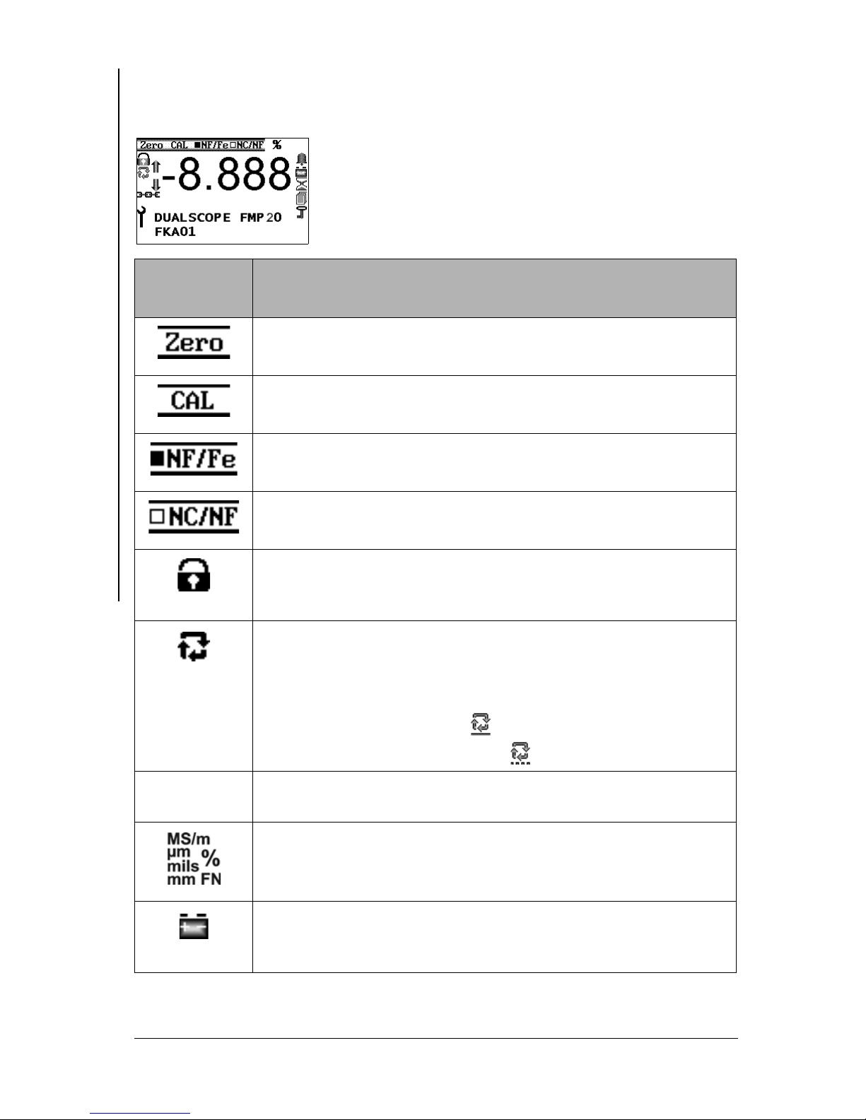
3.1 LCD Display
The LCD display consists of several display elements.
When powering up the instrument using ON/OFF, all
display elements will appear briefly at the same time.
Display
element
Description of the Instrument
Explanation
A normalization is performed (on the uncoated specimen =
base material).
A calibration is carried out.
The measurement uses the magnetic induction method.
The measurement uses the e dd y curre n t me th od .
Padlock:
Restricted operating mode is enabled, i.e., the keys ZERO and
CAL are not active, the service functions cannot be retrieved.
Arrow circle: “Free-running” display is enabled, measurements
are displayed continuously when the probe is placed on the
specimen
Alternatively:
Area measurement display
Automatic measurement display
-8.8.8.8
Page 4 Brief Guide FMP10 / FMP20
Numeric elements for presenting readings, errors and warning
messages.
Unit of measurement for the displayed reading.
Battery: The battery must be replaced or the rechargeable battery must be charged because the voltage has dropped below a
minimum value.
Page 8

Display
element
Explanation
Hourglass: Measurements are currently not possible because
an instrument-internal routine is running.
...SCOPE ...
FKA...
Information lines:
Instrument type
Instrument-internal software version
3.2 Control Panel Key Functions
Key Function
DEL z Deletes the last measured reading
z Returns to the previous menu or
z Cancels the procedure
FINAL-RES Retrieves the final result
ON/OFF Turns the instrument on and off
ZERO Retrieves the normalization
CAL Retrieves the corrective calibration
∧
z Changes the information shown on the LCD display.
Description of the Instrument
z The display will change faster if
3 seconds.
∨
SEND Transfers the values to a connected computer.
ENTER Confirms entries
z Changes the information shown on the LCD display.
z Turns the “free-running” display mode on/off.
z The display will change faster if
3 seconds.
5 x ENTER: Calls the service functions
The instrument settings in the
password-protected. “157” will be displayed after pressing EN-
TER 5 times. Press ∧ 2 times to increase this value to the factory-default
ENTER.
password “159” and confirm the entry with
∧ is pressed for longer than
∨ is pressed for longer than
Service Functions menu are
Brief Guide FMP10 / FMP20 Page 5
Page 9

4 Probe handling
z Always hold the probe at its grip sleeve (right figure).
z Always place the probe gently and at a right angle on
Probe handling
the specimen surface.
z Slide the grip sleeve to the specimen surface such that
the sleeve rests on the specimen (center and bottom
Figure, right).
z With the default setting, a beep will signal the mea-
surement capture.
z Lift the probe off the specimen before making the
next measurement.
Avoid hard impacts.
Do not allow the probe to hover directly above
the surface. Doing so will lead to erroneous
readings.
Do not bend the probe connector cable! Doing
so can lead to broken wires.
5 The Path to the First Measurement
z Instrument Start Up ( 6 ‘System Setup’, beginning on Page 7)
insert the batteries, connect the probe and turn on the instrument
z Adjust the instrument and probe to the base material to be measured
( 7 ‘Adjusting Instrument and Probe’, beginning on Page 11) Normalization and Calibration
z Make measurements on the specimen ( 8 ‘Measuring’, beginning on
Page 16)
Page 6 Brief Guide FMP10 / FMP20
Page 10

6 System Setup
1.
-
+
-
-
-
+
+
+
LR6 1.5V
LR6 1.5V
LR6 1.5V
LR6 1.5V
Observe the cor-
rect polarity when
installing the bat-
teries.
2.
3.
6.1 Install the batteries/rechargeable batteries
Use only type MIGNON, 1.5 V, LR6 - AA - AM3 - MN1500 batteries or 4
individual rechargeable batteries 1.2 V 2400 mAh Type AA.
Using other batteries may lead to instrument damage.
Use only non-damaged batteries/rechargeable batteries.
System Setup
Fig. 6-1 Installing batteries
If the battery voltage is too low, the instrument will turn off
automatically!
Brief Guide FMP10 / FMP20 Page 7
Page 11

6.2 Probe connection
1.
Probe connector plug
Connector socket
Instrument
2.
A measurement probe must be connected to the instrument to make coat ing thickness measurements. This must be an appropriate probe suitable for the base material.
Connect probes only when the instrument is off!
System Setup
To turn the instrument off: Press the ON/OFF key on the right side of the
control panel. The LCD display is not backlit and no characters are visible.
Protect the instrument and accessories from electrostatic
charges!
Electrical discharges may damage internal components or
delete internal memories.
Such discharges may occur, for example, when connecting the probe to
the instrument. Thus, please ensure that the person connecting a probe
is properly grounded.
It is recommended to store the instrument with the connected probe.
Fig. 6-2 Connecting a probe
Page 8 Brief Guide FMP10 / FMP20
Page 12

6.3 Instrument On/Off
Turning the instrument on
Detail of the LCD
Explanation
display
Press the ON/OFF key to turn on the instrument.
An audible signal will sound.
A monitoring routine will run automatically. All display ele-
ments of the LCD display will appear briefly at the same
time ( Page 4).
At the end of the monitoring routine, the instrument is
ready to make measurements. The icon of the measurement method of the connected probe is displayed
( Page 10).
[μm] or [mm] or [mils]:
Unit of measurement for the displayed reading
[Thickn.]: Measurement program “Coating thickness”
(alternative display options can be set from the service
functions in menu option Measurement/Display)
System Setup
[n=]: Number of the stored measurements
Brief Guide FMP10 / FMP20 Page 9
Page 13

Measurement Method of the Connected Probe
Display Explanation
[NF/Fe] Magnetic induction probe connected.
[NC/NF] Eddy current probe connected
System Setup
[NF/Fe NC/NF] Dual probe connected and dual method [both] set (i.e., in
the open application, both measurement methods can be
used to make measurements).
[NF/Fe NC/NF] Dual probe connected and dual method [NF/Fe] set (i.e.,
in the open Application, only the magnetic induction method can be used to make measurements). Or: The probe
was last placed on an Fe base material.
[NF/Fe NC/NF] Dual probe connected and dual method [NC/NF] set (i.e.,
in the open Application, only the eddy current method can
be used to make measurements).
Or: The probe was last placed on an NF base material.
Turning Off the Instrument
Press the ON/OFF key to turn the instrument off manually.
The instrument shuts down automatically if for about 5 minutes no measurements
are made or no key is pressed.
Page 10 Brief Guide FMP10 / FMP20
Page 14

7 Adjusting Instrument and Probe
The following options exist after the instrument is turned on:
1.
The instrument recognizes the connected probe. The measurement screen
appears on the LCD display. The display of the measurement method does
not flash. In this case, you can start immediately making measurements.
2.
If the instrument is turned on and a probe other than the one used last is
connected, the following display will appear: “W006 Probe changed”. The
probe must be assigned ( Chapter 7.1).
7.1 Assigning a New Probe
Key sequ. /
Action
Detail of the LCD
display
Explanation
This warning appears briefly after powerup if a probe other than the last one used
is connected to the instrument.
Adjusting Instrument and Probe
After a brief time, the display to the left will
appear.
Example: FD10 = Name of the connected
probe
DEL: Probe assignment starts
ENTER: Probe will not be assigned, mea-
surement method display flashes
DEL DEL: All stored readings will be deleted.
ENTER: The probe will not be assigned,
measurement method display continues to
flash
ZERO and CAL appear on the display. A
normalization and a corrective calibration
must be performed
Page 12).
( beginning on
Brief Guide FMP10 / FMP20 Page 11
Page 15

7.2 Normalization
With the normalization, a new zero point is established for the calibration curve
and stored in the instrument.
Required materials
Reference part: Uncoated part from the production.
Procedure
Key sequ. /
Action
ZERO Use ZERO to start the normalization.
Adjusting Instrument and Probe
Detail of the LCD
display
Explanation
ZERO appears and remains on the LCD
display while the normalization is performed.
[s]: Standard deviation
[n]: Number of measurements
[Base material (Fe/NF)]: Measurements
should be performed on an uncoated specimen (Fe or NF display for the type of base
material).
When using dual probes, the type of base
material will be displayed only after the 1st
measurement is completed.
Perform measurements on the uncoated
specimen (base material).
Make measurements at various points of
the reference area.
The mean value of all readings obtained
for the normalization will be displayed.
ENTER A confirmation indicating that the normal-
Page 12 Brief Guide FMP10 / FMP20
ization has been carried out successfully
appears.
Pressing ENTER confirms the message.
Page 16

Key sequ. /
Action
ENTER The new characteristic will be computed
Detail of the LCD
display
Explanation
automatically and stored. The instrument
is again ready to make measurements.
7.3 Corrective Calibration
Options
One-point calibration with one calibration standard: A new zero point and
one additional point are established for the calibration curve and stored in the instrument.
Two-point calibration with two calibration standards: A new zero point and
two additional points are established for the calibration curve and st ored in the
instrument.
Adjusting Instrument and Probe
Required materials
z Reference part (uncoated part from the production)
z Calibration Standards
Selecting the Calibration Standards for the Corrective Calibration
A corrective calibration using the calibration standards included with the probe
shipment provides the best measuring precision for the entire measurement range
of the probe.
Brief Guide FMP10 / FMP20 Page 13
Page 17

Procedure
Key sequ. /
Action
CAL Use CAL to start the corrective calibration.
Adjusting Instrument and Probe
Detail of the LCD
display
Explanation
CAL appears and remains on the LCD dis-
play while the corrective calibration is performed.
[s]: Standard deviation
[n]: Number of measurements
[base material (Fe/NF)]: Measurements
should be performed on an uncoated specimen (Fe or NF display for the type of base
material), i.e., a Normalization is carried
out.
When using dual probes, the type of base
material will be displayed only after the 1st
measurement is completed.
Perform measurements on the uncoated
specimen (base material) (normalization).
Make measurements at various points of
the reference area.
The mean value of all readings obtained
for the normalization will be displayed.
ENTER
Page 14 Brief Guide FMP10 / FMP20
[Entry:
nominal thickness value of the calibration
standard. The rated value is printed onto
the calibration standard.
The rated value can be set faster if a measurement is performed on the calibration
standard and then the rated value is corrected using the arrow keys.
[CAL Nom. v . 1: 23.70]: Display of the set
rated value for the thickness of the calibration standard (Example: 23.7 µm)
∧∨]: Use the arrow keys to set the
Page 18

Key sequ. /
Action
Detail of the LCD
display
Explanation
Place the calibration standard 1 (in the example with a thickness of 23.7 µm) on the
uncoated specimen and perform measurements.
Make individual measurements at various
points of the reference area. Displayed is
the mean value of all measurements performed for this step.
∧ or ∨ [Entry: ∧∨]: Use the arrow keys to set the
nominal thickness value of the calibration
standard. The rated value is printed onto
the calibration standard. The rated value
can be set faster if a measurement is performed on the calibration standard and
then the rated value is corrected using the
arrow keys.
This step is not required if - as shown in
the example - the rated value for the thickness of the calibration standard coincides
with the stored thickness.
Adjusting Instrument and Probe
ENTER If a corrective calibration is desired with 2
standards, proceed in the same manner
with calibration standard #2.
Otherwise: Use ENTER to end the corrective calibration.
The new characteristic will be computed
automatically and stored.
The instrument is again ready to make
measurements.
ENTER A confirmation indicating that the correc-
tive calibration has been carried out successfully appears.
Pressing ENTER confirms the message.
Brief Guide FMP10 / FMP20 Page 15
Page 19

7.4 Reference Measurements
z Perform several reference measurements by measuring the thickness of a
calibration standard placed on the uncoated reference area in order to verify
a correct normalization or corrective calibration. The thickness of the stan-
Measuring
dard should be close to the nominal thickness value of the coating to be measured.
z If the obtained mean value is within the guaranteed error limits stated on the
foil, delete the readings of the reference measurement before starting with
the measurements on your specimens.
z If the mean value is not within the guaranteed error limits, perform a correc-
tive calibration, or repeat the corrective calibration, respectively.
8 Measuring
The information stated in the operators's manual must be
observed when making measurements!
To make a measurement, place the probe at a right angle on the specimen surface.
The probe can be lifted off after the measurement acquisition, i.e., after the reading appears on the LCD display. The instrument is again ready to make measurements.
Observe the following during the measurement:
z Measurements should be made within the reference area.
z To avoid erroneous readings, do not allow the probe to hover above the spec-
imen.
z How high the probe should be lifted off depends on the measurement range
of the probe. To obtain a correct air value, the distance to the specimen
should be at least 3 to 4 times the max. measurable coating thickness.
z To allow sufficient time for a measurement acquisition, the time between
individual measurements must be greater than 0.5 seconds.
Page 16 Brief Guide FMP10 / FMP20
Page 20

9 Service Functions
How to access the “Service function” menu
Key sequ. /
Action
ON/OFF
5 x ENTER
2 x ∧
ENTER The Service settings menu will be dis-
Detail of the LCD
display
Explanation
Use ON/OFF to turn the instrument on
After pressing ENTER 5 times, the identification number 157 appears on the LCD
display.
Enter the identification number 159 by
pressing the arrow key ∧ 2 times.
Use ENTER to confirm the setting.
played.
Press the arrow keys
desired service function.
∧ or ∨ to select the
How to exit the “Service functions” menu
Service Functions
Key sequ. /
Action
DEL Press the DEL key to exit the Service func-
Explanation
tions menu.
The instrument is ready to make measurements.
Brief Guide FMP10 / FMP20 Page 17
Page 21

Service Functions Overview
Service menu Functions
System Language
Contrast
Lighting
Autom. off
Initialization
Service Functions
USB Send free-running mode
Instrument mode Restr. Mode
Analog display
Measurement Audible signal
Measurement effect
External start
Measuring mode - Standard/
Area measurement/Autom atic measurement
Display
dual method
Units metric/imperial
Storage mode save/don't save/delete on off
Master calibration Performing a master calibration
About ... Information about the instrument configuration
Page 18 Brief Guide FMP10 / FMP20
Page 22

Sales and Service Departments
DKD-D-33101
Accredited acc. to
DIN EN ISO/IEC 17025
Valid for Helmut Fischer AG and
Branch Offices
- all around the world -
GERMANY
HELMUT FISCHER GMBH
Industriestraße 21
D-71069 Sindelfingen
: +49 (0) 70 31 / 30 3-0
Fax: +49 (0) 70 31 / 30 3-79
mail@helmut-fischer.de
www.helmut-fischer.com
GREAT BRITAIN
FISCHER INSTRUMENTATION
(G.B.) LTD.
Gordleton Industrial Park
Hannah Way · Pennington
GB-Lymington/Hants SO41 8JD
: (+44) 15 90 68 41 00
Fax: (+44) 15 90 68 41 10
mail@fischergb.co.uk
www.fischergb.co.uk
SWITZERLAND
HELMUT FISCHER AG
Moosmattstrasse 1 · Postfach · CH-6331 Hünenberg
: (+41) 41 785 08 00 · Fax: (+41) 41 785 08 01
switzerland@helmutfischer.com
www.helmutfischer.com
Branch Offices of Helmut Fischer AG, Switzerland:
SPAIN
FISCHER INSTRUMENTS, S.A.
C/Almogàvers 157 · 3a Planta
E-08018 Barcelona
: (+34) 93 309 79 16
Fax: (+34) 93 485 05 94
spain@helmutfischer.com
www.helmutfischer.com
ITALY
HELMUT FISCHER S.R.L.
Tecnica di Misura
Via Columella 40 · I-20128 Milano
: (+39) 0 22 55 26 26
Fax: (+39) 0 22 57 00 39
italy@helmutfischer.com
www.helmutfischer.com
USA
FISCHER TECHNOLOGY, INC.
750 Marshall Phelps Road
Windsor, CT 06095 USA
: (+1) 86 06 83 07 81
Fax: (+1) 86 06 88 84 96
Watts 800 243 84 17
info@fischer-technology.com
www.fischer-technology.com
JAPAN
FISCHER INSTRUMENTS K.K.
Shinmei 1-9-16· Souka-shi
Saitama-ken 340-0012 · Japan
: (+81) 489 29 34 55
Fax: (+81) 489 29 34 51
japan@helmutfischer.com
www.helmutfischer.com
FRANCE
FISCHER INSTRUMENTATION
ELECTRONIQUE
Parc d'Activités Nord du Pas
du Lac · 5, rue Michaël Faraday
F-78180 Montigny le Bretonneux
BP 289 · F-78053 St Quentin en
Yvelines Cedex
: (+33) (0) 1 30 58 00 58
Fax: (+33) (0) 1 30 58 89 50
france@helmutfischer.com
www.helmutfischer.com
CHINA
NANTONG FISCHER
INSTRUMENTATION LTD.
7F, No. 2 Building
2601 Songhuajiang Road
Shanghai 200437 · P.R.C.
: (+86) 21 65 55 74 55
Fax: (+86) 21 65 55 24 41
china@helmutfischer.com
www.helmutfischer.com
HONG KONG
FISCHER INSTRUMENTATION
(FAR EAST) LTD.
Unit 2901 · Level 29
Metroplaza Tower 2
223 Hing Fong Road
Kwai Chung, N.T.
Hong Kong
: (+852) 24 20 11 00
Fax: (+852) 24 87 02 18
hongkong@helmutfischer.com
www.helmutfischer.com
SINGAPORE
FISCHER INSTRUMENTATION (S)
PTE LTD.
102 E Pasir Panjang Road #04-04
Citilink Warehouse Complex
Singapore 118529
: (+65) 62 76 67 76
Fax: (+65) 62 76 76 67
singapore@helmutfischer.com
www.helmutfischer.com
THE NETHERLANDS
HELMUT FISCHER
MEETTECHNIEK B.V.
Tarasconweg 10
NL-5627 GB Eindhoven
Postbus 1828
NL-5602 CA Eindhoven
: (+31) 40 248 22 55
Fax: (+31) 40 242 88 85
netherlands@helmutfischer.com
www.helmutfischer.com
INDIA
FISCHER MEASUREMENT
TECHNOLOGIES (INDIA) PVT. LTD.
Florida Amenity
S. No. 41, Keshav Nagar
Mundhwa
IN-Pune 411036
: (+91) 20 26 82 20 65
Fax: (+91) 20 26 82 20 75
india@helmutfischer.com
www.helmutfischer.com
Page 23

 Loading...