

Page 1

Operators Manual
FERITSCOPE® FMP30
Coating Thickness Material TestingMicrohardnessMaterial Analysis
Page 2

Page 2 Operators Manual FERITSCOPE® FMP30
Page 3

Order number: Version 1.0
902-097 08/08
FERITSCOPE® FMP30
Operators Manual
Determination the ferrite content
of austenitic and DUPLEX stainless steel and
determination of the ratio of
martensite in austenitic stainless steels
© 2008 Copyright by
Helmut Fischer GmbH
Institut für Elektronik und Messtechnik, Sindelfingen (Germany).
All rights reserved. No part of this manual may be reproduced by any
means (print, photocopy, microfilm, or any other method) or processed,
multiplied or distributed by electronic means without the written consent
of Helmut Fischer GmbH Institut für Elektronik und Messtechnik.
Operators Manual FERITSCOPE® FMP30 Page 3
Page 4

Table of Contents
1 Important Information . . . . . . . . . . . . . . . . . . . . . . . . . . 9
1.1 Trademarks and Liabilities . . . . . . . . . . . . . . . . . . . . . . . 9
1.2 Symbols and Conventions Used in the Manual . . . . . . . 9
1.3 Intended Use . . . . . . . . . . . . . . . . . . . . . . . . . . . . . . . . 10
1.4 General Information . . . . . . . . . . . . . . . . . . . . . . . . . . . 10
1.5 Requirements on the Operating Personnel . . . . . . . . . 10
1.6 Power Connection . . . . . . . . . . . . . . . . . . . . . . . . . . . . 11
1.7 Environmental Conditions . . . . . . . . . . . . . . . . . . . . . . 11
1.8 Probe Handling . . . . . . . . . . . . . . . . . . . . . . . . . . . . . 12
1.9 Handling, Storage and Transport of the Base and
the Calibration Standards . . . . . . . . . . . . . . . . . . . . . . 13
1.10 Instrument Repairs . . . . . . . . . . . . . . . . . . . . . . . . . . . 14
1.11 Warranty . . . . . . . . . . . . . . . . . . . . . . . . . . . . . . . . . . . 14
2 Description of the Instrument . . . . . . . . . . . . . . . . . . 15
2.1 LCD-Display . . . . . . . . . . . . . . . . . . . . . . . . . . . . . . . . 16
2.2 Control Panel Key Functions . . . . . . . . . . . . . . . . . . . 18
2.3 Accessories . . . . . . . . . . . . . . . . . . . . . . . . . . . . . . . . . 23
2.3.1 Probes . . . . . . . . . . . . . . . . . . . . . . . . . . . . . . . . . . . 23
2.3.2 Base and Calibration Standards . . . . . . . . . . . . . . . . 24
2.3.3 Printer . . . . . . . . . . . . . . . . . . . . . . . . . . . . . . . . . . . . 25
2.4 Technical Data . . . . . . . . . . . . . . . . . . . . . . . . . . . . . . . 26
2.5 Contents of Shipment and Options . . . . . . . . . . . . . . . 27
2.5.1 Standard Contents of Shipment of the Instrument . . . 27
2.5.2 Options . . . . . . . . . . . . . . . . . . . . . . . . . . . . . . . . . . . 28
3 System Setup, Maintenance and Cleaning . . . . . 29
3.1 Voltage supply . . . . . . . . . . . . . . . . . . . . . . . . . . . . . . . 30
3.1.1 Power Connection . . . . . . . . . . . . . . . . . . . . . . . . . . . 30
3.1.2 Installing or Replacing Batteries . . . . . . . . . . . . . . . . 31
3.2 Connecting Probes . . . . . . . . . . . . . . . . . . . . . . . . . . . 33
Page 4 Operators Manual FERITSCOPE® FMP30
Page 5

3.3 Instrument: On/Off . . . . . . . . . . . . . . . . . . . . . . . . . . . 36
3.3.1 Measurement Method of the Connected Probe . . . . 36
3.3.2 Power Up . . . . . . . . . . . . . . . . . . . . . . . . . . . . . . . . . 37
3.3.3 Measured Variables . . . . . . . . . . . . . . . . . . . . . . . . . 40
3.3.4 Switching Off the Instrument . . . . . . . . . . . . . . . . . . 41
3.4 Cleaning . . . . . . . . . . . . . . . . . . . . . . . . . . . . . . . . . . . 41
4 Probe Handling . . . . . . . . . . . . . . . . . . . . . . . . . . . . . . . . 42
4.1 Handling During Measurements . . . . . . . . . . . . . . . . . 42
4.2 Assigning a New Probe . . . . . . . . . . . . . . . . . . . . . . 43
5 Applications . . . . . . . . . . . . . . . . . . . . . . . . . . . . . . . . . 45
5.1 Setting Up an Application . . . . . . . . . . . . . . . . . . . . . . 45
5.2 Selecting the Desired Application . . . . . . . . . . . . . . . 48
5.3 Deleting an Application . . . . . . . . . . . . . . . . . . . . . . . . 49
5.4 List of Set Up Applications . . . . . . . . . . . . . . . . . . . . . 50
5.5 Assigning Application Designations . . . . . . . . . . . . . . 52
5.6 Application Specific Settings . . . . . . . . . . . . . . . . . . . . 52
5.6.1 Tolerance Limits . . . . . . . . . . . . . . . . . . . . . . . . . . . 54
5.6.2 Measurement Display Resolution . . . . . . . . . . . . . . 56
5.6.3 Automatic Block Size and Block Creation . . . . . . . . . 57
5.6.4 Auto-Averaging Mode . . . . . . . . . . . . . . . . . . . . . . . . 58
5.6.5 Outlier rejection . . . . . . . . . . . . . . . . . . . . . . . . . . . . 60
5.6.6 Measured Variables . . . . . . . . . . . . . . . . . . . . . . . . . 61
5.7 Linking Applications . . . . . . . . . . . . . . . . . . . . . . . . . . 63
5.7.1 Application Linking Procedure . . . . . . . . . . . . . . . . . . 63
5.7.2 Enabling and Disabling the Linking Mode . . . . . . . . . 64
5.7.3 Example for Linked Applications . . . . . . . . . . . . . . . . 64
6 Normalization, Calibration and Master
Calibration . . . . . . . . . . . . . . . . . . . . . . . . . . . . . . . . . . . . 67
6.1 Information Regarding Normalization, Calibration
and Master Calibration . . . . . . . . . . . . . . . . . . . . . . . . . 67
6.2 Normalization . . . . . . . . . . . . . . . . . . . . . . . . . . . . . . . . 68
6.2.1 Normalization Procedure . . . . . . . . . . . . . . . . . . . . . 69
6.2.2 Documenting the Normalization with a Printer . . . . . 70
Operators Manual FERITSCOPE® FMP30 Page 5
Page 6

6.3 Corrective Calibration . . . . . . . . . . . . . . . . . . . . . . . . . 71
6.3.1 Selecting the Calibration Standards for the
Corrective Calibration . . . . . . . . . . . . . . . . . . . . . . . . . 71
6.3.2 Corrective Calibration Procedure . . . . . . . . . . . . . . . 72
6.3.3 Deleting a Corrective Calibration . . . . . . . . . . . . . . . . 75
6.3.4 Documenting the Corrective Calibration with a
Printer . . . . . . . . . . . . . . . . . . . . . . . . . . . . . . . . . . . 76
6.4 Master Calibration . . . . . . . . . . . . . . . . . . . . . . . . . . . . 77
6.4.1 Selecting the Calibration Standards . . . . . . . . . . . . . 78
6.4.2 Performing a User Master Calibration . . . . . . . . . . . . 78
6.4.3 Master Calibration Procedure . . . . . . . . . . . . . . . . . 79
6.4.4 Displaying Xn Ranges for Calibration Standards
for the Master Calibration . . . . . . . . . . . . . . . . . . . . 83
6.4.5 Documenting the Master Calibration with a Printer . 84
6.5 Determination of the Normalized Countrate Xn of a
Calibration Standard During a Master Calibration . . . 85
7 Measuring . . . . . . . . . . . . . . . . . . . . . . . . . . . . . . . . . . . . . 86
7.1 Preparing for a Measurement . . . . . . . . . . . . . . . . . . 86
7.2 Parameters That Influence the Ferrite Content
Measurement . . . . . . . . . . . . . . . . . . . . . . . . . . . . . . . . 87
7.3 Making a Measurement . . . . . . . . . . . . . . . . . . . . . . . 87
7.3.1 Measurement Acquisition . . . . . . . . . . . . . . . . . . . . 89
7.3.2 Measurements With External Start Enabled . . . . . . . 90
7.3.3 Automatic Measurement Acquisition . . . . . . . . . . . . 90
7.3.4 Audible Signals After the Measurement Acquisition 93
7.3.5 Measurements With Tolerance Limits Enabled . . . . 94
7.3.6 Measurements With a Fixed Block Size . . . . . . . . . . 94
7.3.7 Measurements in Auto-Averaging Mode . . . . . . . . . 96
7.3.8 Measurements With Outlier Rejection Enabled . . . . 97
7.4 Documenting the Measurement with a Printer . . . . . . . 98
7.5 Erroneous Readings . . . . . . . . . . . . . . . . . . . . . . . . . 101
7.5.1 Deleting Erroneous Readings . . . . . . . . . . . . . . . . 101
7.5.2 Deleting All Readings of a Block That Has
Not Been Closed . . . . . . . . . . . . . . . . . . . . . . . . . . 101
7.5.3 Deleting All Readings of an Application . . . . . . . . . 101
7.5.4 Overwriting Individual Erroneous Measurements
at a Later Time . . . . . . . . . . . . . . . . . . . . . . . . . . . . 102
7.6 Measurements in the Free-Running Display Mode . 104
Page 6 Operators Manual FERITSCOPE® FMP30
Page 7

7.6.1 Turning the Free-Running Display Mode On/Off . . . 105
7.6.2 Procedure For Making Measurements With the
Free-Running Display Mode . . . . . . . . . . . . . . . . . 106
7.6.3 Analog Display . . . . . . . . . . . . . . . . . . . . . . . . . . . . 107
7.7 Measurements in Standard and
Matrix Measuring Mode . . . . . . . . . . . . . . . . . . . . . . 109
7.7.1 The Standard Measuring Mode . . . . . . . . . . . . . . . . 109
7.7.2 Making Measurements in the
Standard Measuring Mode . . . . . . . . . . . . . . . . . . . 110
7.7.3 The Matrix Measuring Mode . . . . . . . . . . . . . . . . . 111
7.7.4 Making Measurements in the
Matrix Measuring Mode . . . . . . . . . . . . . . . . . . . . . . 112
7.7.5 Assigning Block Designations . . . . . . . . . . . . . . . . 115
7.8 Correction Factors . . . . . . . . . . . . . . . . . . . . . . . . . . . 116
7.8.1 Influence of the Specimen Curvature . . . . . . . . . . . 116
7.8.2 Influence of the Specimen Thickness . . . . . . . . . . . 119
7.8.3 Influence of the Cladding Thickness . . . . . . . . . . . . 120
7.8.4 Influence of the Edge Distance on the
Measurement Location . . . . . . . . . . . . . . . . . . . . . . 122
8 Evaluation . . . . . . . . . . . . . . . . . . . . . . . . . . . . . . . . . . . . 124
8.1 Evaluation of the Current Block “Block Result” . . . . 125
8.1.1 Documenting the Block Result With a Printer . . . . . 128
8.1.2 Printout of the List of Single Readings . . . . . . . . . . . 129
8.1.3 Computed parameters - Block result . . . . . . . . . . . . 130
8.2 Evaluation of the Open Application “Final Result” . . 131
8.2.1 Documenting the Final Result with a Printer . . . . . 133
8.2.2 Computed Parameters - Final Result . . . . . . . . . . . 135
8.2.3 Histogram . . . . . . . . . . . . . . . . . . . . . . . . . . . . . . . 136
9 Data Transfer Using USB . . . . . . . . . . . . . . . . . . . . 138
9.1 USB Connection to a PC . . . . . . . . . . . . . . . . . . . . . 139
9.2 Installing the USB Drivers . . . . . . . . . . . . . . . . . . . . . 139
9.3 Transfer of the Measurement Data to the Computer 140
9.3.1 Online Operation . . . . . . . . . . . . . . . . . . . . . . . . . . . 140
9.3.2 Offline Operation . . . . . . . . . . . . . . . . . . . . . . . . . . . 141
9.3.3 Transferring Data With a Group Separator . . . . . . . 141
9.4 Transmission from the PC to the Instrument . . . . . . . 141
9.4.1 Transfer Formats . . . . . . . . . . . . . . . . . . . . . . . . . . 141
Operators Manual FERITSCOPE® FMP30 Page 7
Page 8

9.4.2 Control Commands . . . . . . . . . . . . . . . . . . . . . . . . . 142
9.5 Connecting a Printer . . . . . . . . . . . . . . . . . . . . . . . . 146
9.5.1 Print Output . . . . . . . . . . . . . . . . . . . . . . . . . . . . . . . 146
10 Instrument Settings - Service Function Menu 147
10.1 Service Menu Overview . . . . . . . . . . . . . . . . . . . . . . . 148
10.2 System . . . . . . . . . . . . . . . . . . . . . . . . . . . . . . . . . . . . 149
10.2.1 Language . . . . . . . . . . . . . . . . . . . . . . . . . . . . . . . . 149
10.2.2 Time . . . . . . . . . . . . . . . . . . . . . . . . . . . . . . . . . . . . 150
10.2.3 Date . . . . . . . . . . . . . . . . . . . . . . . . . . . . . . . . . . . . 151
10.2.4 Date format . . . . . . . . . . . . . . . . . . . . . . . . . . . . . . . 152
10.2.5 Contrast . . . . . . . . . . . . . . . . . . . . . . . . . . . . . . . . . 153
10.2.6 Lighting . . . . . . . . . . . . . . . . . . . . . . . . . . . . . . . . . . 154
10.2.7 Automatic Switch Off . . . . . . . . . . . . . . . . . . . . . . . 156
10.2.8 Re-Initialization of the Instrument . . . . . . . . . . . . . . 157
10.3 Evaluation . . . . . . . . . . . . . . . . . . . . . . . . . . . . . . . . . 159
10.3.1 Block Result . . . . . . . . . . . . . . . . . . . . . . . . . . . . . . 159
10.3.2 Histogram . . . . . . . . . . . . . . . . . . . . . . . . . . . . . . . . 160
10.4 USB . . . . . . . . . . . . . . . . . . . . . . . . . . . . . . . . . . . . . . 161
10.4.1 Output . . . . . . . . . . . . . . . . . . . . . . . . . . . . . . . . . . 161
10.4.2 Group Separator . . . . . . . . . . . . . . . . . . . . . . . . . . 162
10.4.3 Send Free-Running Mode . . . . . . . . . . . . . . . . . . . 163
10.5 Printing . . . . . . . . . . . . . . . . . . . . . . . . . . . . . . . . . . . . 164
10.5.1 Printer Selection . . . . . . . . . . . . . . . . . . . . . . . . . . 164
10.5.2 Left Margin Setting . . . . . . . . . . . . . . . . . . . . . . . . . . 165
10.5.3 Print Individual Single Readings . . . . . . . . . . . . . . . 166
10.5.4 Block Result . . . . . . . . . . . . . . . . . . . . . . . . . . . . . . . 167
10.5.5 Final Result . . . . . . . . . . . . . . . . . . . . . . . . . . . . . . . 168
10.5.6 Histogram . . . . . . . . . . . . . . . . . . . . . . . . . . . . . . . . 169
10.5.7 Auto Formfeed . . . . . . . . . . . . . . . . . . . . . . . . . . . . . 170
10.6 Instrument Mode . . . . . . . . . . . . . . . . . . . . . . . . . . . 171
10.6.1 Restricted Operating Mode . . . . . . . . . . . . . . . . . . . 171
10.6.2 Analog Display . . . . . . . . . . . . . . . . . . . . . . . . . . . . 173
10.6.3 Matrix Mode . . . . . . . . . . . . . . . . . . . . . . . . . . . . . . 174
10.6.4 Linking Applications . . . . . . . . . . . . . . . . . . . . . . . . . 177
10.7 Measurement . . . . . . . . . . . . . . . . . . . . . . . . . . . . . . . 178
10.7.1 Audible Signal . . . . . . . . . . . . . . . . . . . . . . . . . . . . . 178
10.7.2 Measurement Effect . . . . . . . . . . . . . . . . . . . . . . . . 179
10.7.3 External Start . . . . . . . . . . . . . . . . . . . . . . . . . . . . . 180
Page 8 Operators Manual FERITSCOPE® FMP30
Page 9

10.7.4 Measuring Mode - Standard/Area Measurement/
Automatic Measurement . . . . . . . . . . . . . . . . . . . . 182
10.7.5 Unit . . . . . . . . . . . . . . . . . . . . . . . . . . . . . . . . . . . . . 184
10.7.6 Measured Variable . . . . . . . . . . . . . . . . . . . . . . . . 185
10.8 Storage Mode . . . . . . . . . . . . . . . . . . . . . . . . . . . . . 187
10.9 Performing a Master Calibration . . . . . . . . . . . . . . . . 187
10.10 About ... . . . . . . . . . . . . . . . . . . . . . . . . . . . . . . . . . . . 188
10.11 Documentation of the Instrument Configuration . . . 188
11 Malfunctions and Messages . . . . . . . . . . . . . . . . . . 190
11.1 Malfunctions . . . . . . . . . . . . . . . . . . . . . . . . . . . . . . . 190
11.2 Messages on the LCD Display . . . . . . . . . . . . . . . . . 194
12 Glossary . . . . . . . . . . . . . . . . . . . . . . . . . . . . . . . . . . . 205
12.1 Terms and Formula Symbols . . . . . . . . . . . . . . . . . . . 205
12.2 Additional Literature . . . . . . . . . . . . . . . . . . . . . . . . . . 230
12.2.1 Statistics and ferrite content measurement . . . . . . . 230
12.2.2 Standards . . . . . . . . . . . . . . . . . . . . . . . . . . . . . . . . 231
13 Index . . . . . . . . . . . . . . . . . . . . . . . . . . . . . . . . . . . . . . . . . 233
Operators Manual FERITSCOPE® FMP30 Page 9
Page 10

Page 10 Operators Manual FERITSCOPE® FMP30
Page 11

1 Important Information
1.1 Trademarks and Liabilities
FERITSCOPE® is a registered trademark of the Helmut Fischer GmbH Institute
for Electronics and Metrology.
The fact that the trademark characters ® and ™ may be missing
does not indicate that a name is a free trademark.
Great care has been exercised in creating this operator's manual. The Helmut Fischer GmbH Institute for Electronics and Metrology assumes no liability for potentially remaining erroneous or incomplete statements and their results. We
would, however, appreciate if you can make us aware of potentially existing errors or incomplete information.
1.2 Symbols and Conventions Used in the Manual
The following symbols and conventions are used in this manual:
Indicates safety information referring to danger for persons and warnings regarding damage to the measuring
instrument or to accessories.
Indicates particularly important information and hints.
Indicates a reference to a page or chapter in this manual.
1.
Operation to be carried out by the operator at the instrument.
Important Information
z
ENTER Writing convention for instrument keys and command buttons on the
Operators Manual FERITSCOPE® FMP30 Page 9
Listing.
display.
Page 12

1.3 Intended Use
The FERITSCOPE® FMP30 is to be used to determine the ferrite content of austenitic and DUPLEX steel and to determine the portion of deformation martensite
in austenitic materials.
Only accessories recommended and approved by the Helmut Fischer GmbH Institute for Electronics and Metrology ( beginning on Page 23) may be connected to this instrument.
Important Information
1.4 General Information
The values shown for the measured ferrite contents and the texts of the
information lines of the LCD display serve as examples for possible displays. It is entirely possible that different values appear on the LCD display or in the printout without having made any mistakes.
1.5 Requirements on the Operating Personnel
The instrument should be operated only by staff trained for
this purpose!
In addition, basic knowledge of metrology according to DIN 1319 is essential for
performing correct ferrite content measurements and evaluations.
Basic computer knowledge regarding configuration, operation and programing
as well as knowledge of the software in use, which may be obtained from respective instruction manuals, is required when using the instrument in conjunction
with a computer.
Page 10 Operators Manual FERITSCOPE® FMP30
Page 13

1.6 Power Connection
To avoid damage to the instrument or wrong measurement
results due to a wrong line voltage, the instruments must be
connected to a power outlet only via the AC adapter provided by Helmut Fischer GmbH Institute for Electronics and
Metrology. The line voltage must agree with the line voltage
rating stated on the nameplate of the AC adapter.
1.7 Environmental Conditions
EMC
The instrument complies with the laws concerning electromagnetic compatibility
of instruments (2004/108/EC). The measured values are not influenced by the
highest level of interference mentioned in the EN 61000-6-2 Standard (which references the Standards EN 61000-4-2, EN 61000-4-3 and EN 61000-4-4).
In particular, the instrument is shielded effectively from strong electromagnetic
fields (e.g., motors, power lines, radio transmission towers).
Low Voltage
The instrument adheres to the Low Voltage Directive 2006/95/EC.
Ambient Temperature Range During Operation: +10°C ...+40°C
Important Information
Temperature Range During Storage and Transport: +5°C ... +60°C
Temperature behind glass panes (e.g., in cars) in direct sunlight easily rise above 60°C!
To avoid damage from heat, do not store the instrument or
accessories in such places.
The instrument and accessories (in particular the AC
adapter) must not come in direct contact with water! Risk of
electrical shorts! Instruments or accessories may be operated, kept or stored only in places, where the relative humidity is between 30% and 90% (non-condensing).
Operators Manual FERITSCOPE® FMP30 Page 11
Page 14
Because the instrument and accessories are not acid resistant, avoid direct contact with acid or acidic liquids.
The instrument and accessories are not suited for operation
in explosion-hazard areas!
Protect the instrument and accessories from static charges!
Electrical discharges may damage internal components or
Important Information
delete internal memories.
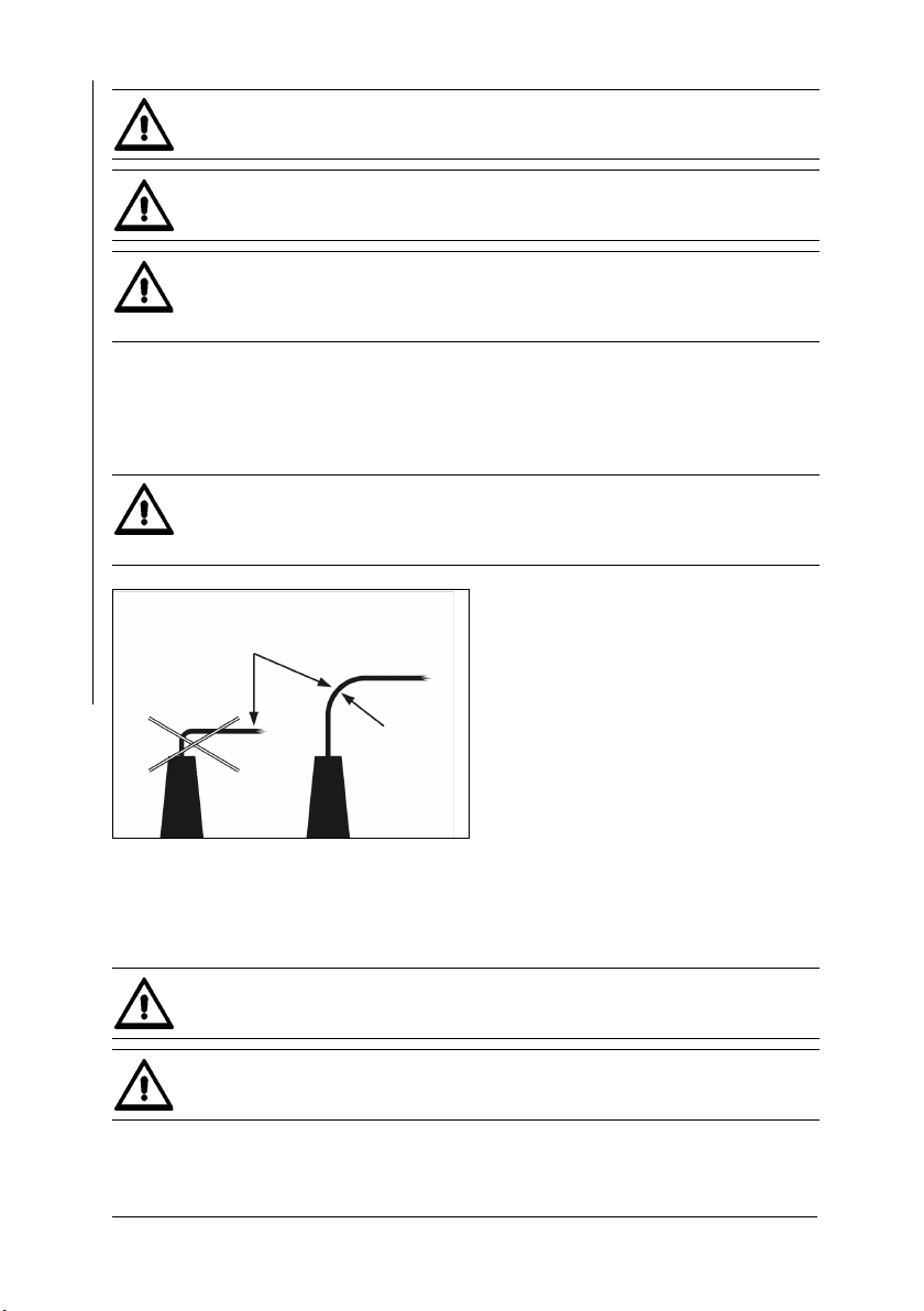
1.8 Probe Handling
To avoid breakage of the wiring, do not bend the probe connector cable! The radius of rolled up probe connector cables
should always be at least 50 mm!
Probeconnector cable
R ≥ 50 mm !
Fig. 1-1 Probe handling
During the measurement, the magnetic poles of the probes are placed directly
onto the specimen. Observe the following to keep wear of the magnetic poles during the contacting measurement to a minimum:
Place the probes speedily yet gently on the specimen surface! Avoid hard impacts!
Do not drag the probe across the specimen surface.
Page 12 Operators Manual FERITSCOPE® FMP30
Page 15

Do not place standard probes on hot or acid-wetted surfaces; do not immerse them in liquids. Special probe models
are available for such applications (ref. the probe data
sheets of the brochure “Measurement Probes and Measurement Aids - Optimized Probes”). You can obtain this brochure from the Helmut Fischer GmbH Institute for
Electronics and Metrology or from your authorized supplier.
1.9 Handling, Storage and Transport of the Base and the Calibration Standards
The instrument is normalized and calibrated using a base and calibration standards (ferrite standards).
Proper condition of the calibration standards is an important prerequisite for a
correct calibration, and thus for a correct measurement.
Observe the following to ensure the proper condition of the calibration standards:
To keep wear of the base and the calibration standards during the contacting measurements to a minimum, use them for the calibration only
and not for test measurements!
Do not soil or scratch calibration standards!
Replace corroded or scratched calibration standards or those with strong
indentations with non-damaged, clean standards.
Important Information
To protect the calibration standards from dirt or damage, keep them in
their supplied case for transporting and storing.
Operators Manual FERITSCOPE® FMP30 Page 13
Page 16

1.10 Instrument Repairs
No repairs should be performed on the instrument.
The instrument may be opened only for replacing rechargeable or regular batteries (
Page 31). Other service opera-
tions on the instrument or the accessories must be
performed only by technical personnel authorized by the
Helmut Fischer GmbH Institute for Electronics and Metrology.
Important Information
1.11 Warranty
The Helmut Fischer GmbH Institute for Electronics and Metrology will assume
no warranties in the following instances:
z Use of instrument or accessories for purposes other than the intended use.
z Connection of accessories not recommended or approved by the Helmut Fis-
cher GmbH Institute for Electronics and Metrology.
z Repairs or structural changes to the instrument or accessories that have not
been carried out by authorized persons.
z Improper handling of instrument or accessories (e.g., use in explosion-haz-
ard or very hot environments).
z Disregard of information in this operator's manual.
Page 14 Operators Manual FERITSCOPE® FMP30
Page 17

2 Description of the Instrument
1
2
3
4
5
6
7
8
9
1 Probe connector socket,
Page 33
2 LCD Display, Page 16
3 Keys for directly retrieving
functions, Page 18
4 USB port for connecting a
printer and a PC
5 ON/OFF key to turn the in-
strument on or off,
Page 36
6 Connector socket for the AC
adapter (included)
7 Cover; additional function
keys can be found under the
cover, Page 18
8 Non-slip rubber supports
9 Foldable instrument stand
10 Battery compartment,
Page 31
Description of the Instrument
10
8
Fig. 2-1 Front and rear view of the instrument, connections
Operators Manual FERITSCOPE® FMP30 Page 15
Page 18

2.1 LCD-Display
The LCD display consists of several display elements. When powering up the instrument using ON/OFF ( Page 36), all display elements will appear briefly at
the same time.
Description of the Instrument
Fig. 2-2 Display elements of the LCD display after power up (example)
Display element Explanation
A normalization is performed (on the base of the calibration standard set) ( beginning on Page 68).
A calibration is carried out ( beginning on Page 71).
Displays the measurement method
Bell:
Tolerance limits are enabled ( beginning on Page 94).
Padlock:
Restricted operating mode is enabled, i.e., the keys
MENU, ZERO and CAL are not active, the service functions cannot be retrieved, applications cannot be deleted
( beginning on Page 171).
Page 16 Operators Manual FERITSCOPE® FMP30
Page 19

Display element Explanation
Arrow circle:
“Free-running display” is enabled, measurements are
displayed continuously when the probe is placed on the
specimen
( beginning on Page 104).
Alternatively:
Area measurement display
Automatic measurement display
-8.8.8.8
Arrow up:
Upper specification limit is exceeded.
Arrow down:
Measurement below lower specification limit.
Both arrows together:
The displayed measurement was recognized as an outlier.
Numeric elements for presenting readings, errors and
warning messages.
Unit of measurement for the displayed reading.
Battery:
The battery must be replaced or the rechargeable battery must be charged because the voltage dropped be-
low a minimum value ( beginning on Page 30).
Hourglass:
Measurements are currently not possible because an instrument-internal routine is running.
Description of the Instrument
Operators Manual FERITSCOPE® FMP30 Page 17
Page 20

Display element Explanation
Chain: Applications that have been set up using the
same probe are linked to each other, i.e., the same normalization and/or corrective calibration is used for determining the measurements for these Applications
( beginning on Page 63).
Sheets: Matrix measuring mode is enabled ( beginning on Page 111).
Key: Measurement block is closed.
Description of the Instrument
Information lines:
...SCOPE ...
FKA...
Instrument type:
Instrument-internal software version
2.2 Control Panel Key Functions
For easier opening of the cover:
1.
Press on the corners of the cover
and then
2.
slide the cover downwards.
Fig. 2-3 Opening the cover of the control panel keys
Page 18 Operators Manual FERITSCOPE® FMP30
Page 21

The following overview provides a brief description of the functions of the individual control panel keys:
Key Function
DEL Deletes the last measured reading
Repeated pressing of DEL: Deletes the readings of the open
block in succession.
2 x DEL: Deletes all readings
.. during normalization:
1x DEL - Deletes the last reading,
2x DEL - Deletes the measurement series of the base material
.. during calibration:
1x DEL - Deletes the last reading,
2x DEL - Deletes the measurement series of the current cali-
bration standard.
Repeated pressing of DEL: Deletes the measurement series
of the previous calibration standard ( beginning on
Page 101).
.. in all menus:
DEL - Returns to the previous menu or cancels the procedure.
FINAL-RES
Retrieving the final result ( beginning on Page 131)
Repeated pressing of FINAL-RES:
Displays the individual components of the final result (mean
value, standard deviation, etc.) in succession.
.. and then ENTER:
Ends the display of the final result (return to the measurement
screen) without deleting the stored values (the current measurement block will not be closed).
.. and then DEL:
Ends the display of the final result (return to the measurement
screen) and deletes the values stored in the open Application.
.. during calibration or normalization:
Enabling and disabling the “free-running” display mode (display of the normalized countrates of the readings; readings will
not be stored and will not be integrated in the calibration or
normalization) or with external start enabled: Triggers a measurement.
Description of the Instrument
Operators Manual FERITSCOPE® FMP30 Page 19
Page 22

Key Function
BLOCK-RES
Description of the Instrument
ON/OFF
Retrieves the block result ( beginning on Page 125
Repeated pressing of BLOCK-RES:
Displays the individual components of the block result (mean
value, standard deviation, etc.) in succession.
.. and then
Ends the display of the block result (return to the measurement
screen) without closing the open measurement block (the cur-
rent measurement series can be continued).
.. and then
Displays the block result of the previous or following measurement block of the open Application.
All block results of the open Application can be retrieved in
succession through repeated pressing of ∨.
.. and then PRINT:
Prints the displayed block result.
.. and then MENU:
Displays the single readings of the evaluated measurement
data block (then all single readings can be displayed by press-
∧ or ∨ ). Pressing MENU again ends the single reading
ing
display.
.. and then DEL:
Deletes the readings of the last measurement data block that
has not been concluded and ends the display of the block result (return to the measurement screen).
.. and then ENTER:
Ends the display of the block results (return to the measurement screen) and closes the current block. The next measurement opens a new block.
Turns the instrument on and off ( beginning on Page 36)
∧:
∨:
ZERO
CAL
Page 20 Operators Manual FERITSCOPE® FMP30
Retrieves the normalization ( beginning on Page 68)
Retrieves the corrective calibration ( beginning on
Page 71)
.. and then CAL:
Cancels the corrective calibration.
.. and then DEL:
Deletes the corrective calibration of the open Application.
Page 23

Key Function
∧
∨
APPL No Selects the desired Application.
With Application selection and tolerance limit input:
Changes the information displayed on the LCD display.
With the calibration: Sets the target value of the used calibration standard that will be displayed after the “CAL Target” notification.
With parameter selection: Selects the desired parameters.
The display will change faster if
seconds.
with external start enabled: Triggers a measurement.
Turns the “free-running” display mode on/off.
With Application selection and tolerance limit input:
Changes the information displayed on the LCD display.
With the calibration: Sets the target value of the used calibration standard that will be displayed after the “CAL Target” notification.
With parameter selection: Selects the desired parameters.
The display will change faster if
seconds.
.. and then DEL:
Deletes the selected Application;
.. and then APPL No:
Displays the probes assigned to the Applications.
.. and then
Selects the desired Application.
.. and then ENTER:
Confirms the selection of the desired Application and returns to
the measurement screen.
∧ or ∨:
∧ is pressed for longer than 3
∨ is pressed for longer than 3
Description of the Instrument
Operators Manual FERITSCOPE® FMP30 Page 21
Page 24

Key Function
MENU Displaying and entering of the application-specific set-
tings:
z Tolerance Limits
z Resolution
z Block size
z i individual values
z Outlier
.. and then
Description of the Instrument
PRINT Output of the values stored in the selected application (includ-
ENTER Confirms entries
Selects the settings to be edited
.. and then PRINT:
Prints or displays a print form of the instrument configuration.
.. and then ENTER:
Confirms the selection of the setting to be edited.
.. and then DEL:
Exits the application-specific settings and returns to the measurement screen.
ing the block results) to a printer or transfer of these values to
a connected computer.
5 x ENTER:
Calls the service functions
The instrument settings in the
password-protected. “157” will be displayed after pressing EN-
TER 5 times. Press ∧, 2 times to increase this value to the fac-
tory-default
ENTER.
∧ or ∨:
Service Functions menu are
password “159” and confirm the entry with
Page 22 Operators Manual FERITSCOPE® FMP30
Page 25

2.3 Accessories
2.3.1 Probes
All probes that can be connected to the instrument are equipped
with a memory chip, a so-called EEPROM, in their connector
plug. Probe-specific information (such as probe type, production number, measurement method or coefficients of the master
characteristic, for example) is stored permanently - even without power supply - in this memory chip, which can be overwritten as many times as desired.
When powering up the instrument, this information is automatically retrieved and processed by the instrument; the instrument “recognizes” the connected probe.
Correct measurements can be performed only if the probe that
is assigned to the open Application is used for the measurement.
( Chapter 4.2 ‘Assigning a New Probe’, beginning on
Page 43).
Fig. 2-4
Probe plug of an
FGAB 1.3-Fe
probe
Various probe models are available for measurements on objects with different
shapes and different surface properties. Special probes with different measurement ranges are available for the following areas of application, for example:
z particularly rough or abrasive surfaces
z Particularly soft surfaces
z damp, acidic contamination on the surface
z particularly thick or thin coatings
z hot surfaces
z Coatings in pipes and bore holes
For available probe models and the probe model best suited for your application,
see the respective probe data sheets of the brochure “Measurement Probes and
Measurement Aids - Optimized Probes”. You can obtain this brochure from
Helmut Fischer GmbH or from your authorized supplier.
Description of the Instrument
Operators Manual FERITSCOPE® FMP30 Page 23
Page 26

2.3.2 Base and Calibration Standards
A so-called base is used for the normalization; for the corrective calibration, one,
two or three calibration standards (ferrite standards) are used in addition to the
base.
Different calibration standard sets (corrective sets) are available for the corrective calibration of the instrument for the different measurement ranges. The calibration standard sets include:
z Base
z 3 calibration standards with ferrite contents according to the desired mea-
surement range
A probe-specific calibration standard set for the master calibration (can be or-
Description of the Instrument
dered as an option) and a probe-specific calibration standard set for the corrective
calibration (included with the probe) are available for each probe model and have
been compiled specifically for this probe model.
You can obtain additional calibration standards on request from Helmut Fischer
GmbH Institute for Electronics and Metrology or from your authorized supplier.
Calibration standards
(Ferrite standards)
Base
Ferrite con-
tent informaSet number of
the calibration
standard set
Fig. 2-5 Calibration standard set (example)
tion
The measurements for the corrective calibration must be performed on
the base and on the calibration standard! Measurements on the plastic
surrounding the base or calibration standard will lead to erroneous measurements.
Page 24 Operators Manual FERITSCOPE® FMP30
Page 27

The measurements for the normalization and for the calibration should
be made within a radius of 10 mm from the center of the base or the calibration standard, respectively.
You can obtain information about available calibration standard sets from the
Helmut Fischer GmbH Institute for Electronics and Metrology or from your authorized supplier.
Certification of the Calibration Standards
The Helmut Fischer GmbH Institute for Electronics and Metrology supplies calibration standard sets complete with a valid certificate.
The certificate includes information about warranties and monitoring of
the test devices.
2.3.3 Printer
For an overview of printers suitable to be connected to the instrument see the
menu Service Functions
/ PRINT ( Chapter 10.5.1 ‘Printer Selection’, be-
ginning on Page 164).
Description of the Instrument
For information about operation, maintenance and care of the printer,
consult the instruction manual of the printer.
Operators Manual FERITSCOPE® FMP30 Page 25
Page 28

2.4 Technical Data
Instrument model
Display Graphical backlit LCD display
Measurable coat-
ings
Measuring modes Magnetic induction measurement method
Dimensions z Instrument: 170 mm x 90 mm x 35 mm (L x W x H)
Description of the Instrument
Weight approx. 340 g (without probe, ready to operate)
Permissible ambi-
ent temperature
during operation
Permissible storage temperature
Permissible relative air humidity
Power
supply
Power consumption
Connectors z Probe:10-pin round plug
Minimum
time between two
measurements
Minimum
lift-off distance
between two measurements
FERITSCOPE
z Ferrite content measurements in weld seams and clad-
dings made of austenitic or duplex steel
z Determination of the portion of deformation martensite
in austenitic materials
z LCD display: 44 mm x 57 mm (L x W)
+10 °C ... +40 °C
+ 5 C°... + 60 °C
30 ... 90% (non-condensing)
z 4 x 1.5 V batteries with about 50 h service life,
(Size AA or Mignon) or
z 4 x 1.5 V NiMH rechargeable batteries with about 45 h
service life at 2100 mAh, (Size AA or Mignon)
z AC adapter 9 V 150 mA, 100V - 230 V
z 0.3 W with the LCD display not illuminated
z 0.5 W with the LCD display illuminated
z AC adapter:2-pin barrel connector
z Mini USB port for connecting a printer and a PC
About 0.2 seconds in the free-running mode
min. 25 mm
®
FMP30
Page 26 Operators Manual FERITSCOPE® FMP30
Page 29

Measurement
range, trueness
and repeatability
precision
Depends on the connected probe
(These and other probe characteristics can be obtained
from the brochure “Measurement Probes and Measurement Aids - Optimized Probes”) of Helmut Fischer GmbH
Institute for Electronics and Metrology or can be requested from your authorized supplier or directly from Helmut
Fischer GmbH Institute for Electronics and Metrology.)
2.5 Contents of Shipment and Options
After receiving the shipment, packaging and content should be checked for potential damage. If the packaging, the content or the accessories show signs of
damage, retain the packaging. It might be needed to assert a claim for damages
versus the shipping company.
It is also advisable to keep the packaging for future transport.
Also verify that all components of the standard content of the shipment and all
ordered options are present. Notify your authorized supplier or he Helmut Fischer
GmbH Institute for Electronics or Metrology if this is not the case.
2.5.1 Standard Contents of Shipment of the Instrument
The standard contents of shipment of the instrument includes:
z Instrument
z Batteries
z Interface cable FMP/PC,
z Carrying and storage case, carrying strap
z CD-ROM with operator's manual and USB drivers
z Brief guide (short form operator's manual)
Description of the Instrument
Operators Manual FERITSCOPE® FMP30 Page 27
Page 30

2.5.2 Options
Available options are:
z AC adapter
z Various measurement probes
z Master and corrective calibration standards sets %Fe/FN
z 1.5 V NiMh rechargeable battery (4 each/unit)
z Charger for NiMh battery
z Support stand V12 for reproducible positioning of measurement
probes on the specimen
z Jig for angle probes for use in the support stand V12 (e.g., for probe
FGABW 1.3)
Description of the Instrument
z Jig for inside probes for use in the support stand V12 (e.g., for probe
FGABI 1.3-150 mm)
z Support stand V12-AM for motor-controlled touch-down and lift-off
of measurement probes
z Guide device V5GW2/TW3 for angle probes for measurements at
recessed or hard to reach areas
z PC-Datex software for transferring measurement data from the instru-
ment to a Microsoft® Excel spreadsheet (add-in module for Microsoft® Excel beginning with Version 95 under Windows® 95 to
Windows
®
Vista)
Page 28 Operators Manual FERITSCOPE® FMP30
Page 31

3 System Setup, Maintenance and Clean-
ing
Connect or disconnect plug-type connectors only when the
instrument is switched off in order to avoid electrical discharge. Connecting the AC adapter or inserting a battery
should be done carried out with the unit turned off as well!
Even a small discharge can delete the instrument memory.
Do not tilt the plug when inserting or unplugging them;
doing so could damage the contact pins of the plugs.
The information in the chapter “1 Important Information” must be
observed!
System setup consists of the following steps:
z Providing the power supply for the instrument
( 3.1 ‘Voltage supply’, beginning on Page 30)
z Connecting a measurement probe to the instrument
( 3.2 ‘Connecting Probes’, beginning on Page 33)
z Connecting a printer (where applicable) to the instrument
( 9.5 ‘Connecting a Printer’, beginning on Page 146)
z Connecting a computer (if desired) to the instrument
( 9 ‘Data Transfer Using USB’, beginning on Page 138)
z Selecting the language for the instrument if your language has not been set
when the instrument was shipped
( 10.2.1 ‘Language’, beginning on Page 149)
System Setup, Maintenance and Cleaning
Operators Manual FERITSCOPE® FMP30 Page 29
Page 32

3.1 Voltage supply
Electrical power can be supplied to the instrument in the following ways:
z with AC adapter (9 V 150 mA, 100 V - 230 V),
z 4 x 1.5 V batteries (AA or mignon) or
z 4 x 1.5 V NiMh rechargeable batteries, 2100 mAh (AA or mignon).
3.1.1 Power Connection
To avoid damage to the instrument or wrong measurement results
due to a wrong line voltage, the instruments must be connected to
a power outlet only via the AC adapter provided by Helmut Fischer
GmbH Institute for Electronics and Metrology. The line voltage
must agree with the line voltage rating stated on the nameplate of
the AC adapter.
To connect the instrument to the line voltage via the AC adapter, the AC adapter
System Setup, Maintenance and Cleaning
must be connected to the instrument and to the line power outlet. The instrument
must be switched off for this purpose!
Page 30 Operators Manual FERITSCOPE® FMP30
Page 33

3.1.2 Installing or Replacing Batteries
Procedure Battery Replacement
1.
2.
Indicator for battery replacement. Batteries or rechargeable batteries should be replaced.
If the battery voltage is too low, the instrument will turn
off automatically.
Use ON/OFF ( Page 36) to switch the instrument off (if not yet done).
Place the instrument with its back pointing up on the table. Open and
remove the battery compartment cover on the rear of the instrument as
depicted below.
System Setup, Maintenance and Cleaning
Fig. 3-1 Opening the battery compartment cover
3.
If old batteries are in the instrument, remove them from the unit. Otherwise, install new batteries directly; observe the correct polarity of the bat-
teries
Disposal: Do not dispose of batteries with regular household waste!
Place damaged or used batteries / rechargeable batteries in designated
collection containers! Please observe the guidelines in your region concerning proper handling of waste electrical and electronic equipment and
accessories.
Operators Manual FERITSCOPE® FMP30 Page 31
Page 34

4.
Close the battery compartment cover.
Observe the cor-
rect polarity when
installing the bat-
teries.
-
-
+
LR6 1.5V
LR6 1.5V
System Setup, Maintenance and Cleaning
Fig. 3-2 Inserting the batteries and closing the battery compartment cover
Use only type MIGNON, 1.5 V, LR6 - AA - AM3 - MN1500 batteries or 4
individual rechargeable batteries 1.2 V 2400 mAh Type AA.
Using other batteries may lead to instrument damage.
LR6 1.5V
LR6 1.5V
+
-
-
+
+
Use only non-damaged batteries/rechargeable batteries.
Page 32 Operators Manual FERITSCOPE® FMP30
Page 35

3.2 Connecting Probes
Connect probes only when the instrument is off!
To turn the instrument off: Press the ON/OFF key on the right side of the
control panel. The LCD display is not backlit and no characters are visible.
Protect the instrument and accessories from electrostatic
charges!
Electrical discharges may damage internal components or
delete internal memories.
Such discharges may occur, for example, when connecting the probe to
the instrument. Thus, please ensure that the person connecting a probe
is properly grounded.
It is recommended to store the instrument with the connected probe.
1.
Use ON/OFF ( Page 36) to switch the instrument off (if not yet done).
2.
If the probe connected to the instrument is to be replaced, unscrew the
knurled nut of the probe plug completely and pull the probe plug carefully
from the connector socket of the instrument.
3.
Plug the probe plug of the new probe into the probe connector socket of
the instrument.
System Setup, Maintenance and Cleaning
Operators Manual FERITSCOPE® FMP30 Page 33
Page 36

When inserting the plug, ensure that the key of the plug fits
into the groove of the socket. Otherwise, an erroneous connection between the instrument and the plug may occur or
the contact pins of the probe plug may be damaged.
Groove (socket)Key (plug)
Fig. 3-3 Probe plug and probe connector socket
4.
Tighten the knurled nut of the probe plug.
System Setup, Maintenance and Cleaning
Hold the plug tight to avoid an unintentional turning of the probe plug.
To avoid damage to the contact pins of the probe plug, only
the knurled nut may be turned! The probe plug must not be
turned in the connector socket.
Page 34 Operators Manual FERITSCOPE® FMP30
Page 37

1.
2.
Probe connector plug
Connector socket
Instrument
Fig. 3-4 Connecting a probe
5.
Use ON/OFF to turn the instrument on again. The instrument automatically recognizes the type of probe connected to it.
Exception: A flashing symbol for the measurement method on the LCD display
indicates that the instrument does not recognize the connected probe. In such a
case:
z A new Application must be set up for the connected probe
( 5.1 ‘Setting Up an Application’, beginning on Page 45) and/or
z The probe must be assigned to the instrument or to the respective Applica-
tion, respectively ( 4.2 ‘Assigning a New Probe’, beginning on Page 43)
or
z The probe that has been linked to the respective Application thus far must be
reconnected.
.
A new corrective calibration must be performed after the probe has been
assigned (
Page 71)!
System Setup, Maintenance and Cleaning
Operators Manual FERITSCOPE® FMP30 Page 35
Page 38
3.3 Instrument: On/Off
To avoid erroneous readings, no metallic objects must be in close
proximity to the probe tip when powering up the instrument.
The minimum distance is 25 mm.
3.3.1 Measurement Method of the Connected Probe
After powering up the instrument, the measurement method [Ferrite] appears on
the LCD display. The unit of measurement for displaying the readings of the current Application is displayed next to it ( 10.7.5 ‘Unit’, beginning on
Page 184).
Unit Explanation
Fe % Ferrite content in ferrite percent
FN Ferrite content in ferrite numbers
System Setup, Maintenance and Cleaning
If [Ferrite] flashes on the display, an Application has not yet been set up
using the connected probe. It is not possible to make measurements
when the display is flashing.
To make measurements, an Application must be set up using the connected probe
5.1 ‘Setting Up an Application’, beginning on Page 45).
(
Page 36 Operators Manual FERITSCOPE® FMP30
Page 39

3.3.2 Power Up
Key sequence
ON/OFF Press the ON/OFF key to power up the in-
Detail of the LCD
display
Explanation
strument.
An audible signal will sound.
A monitoring routine will run. All display elements of the LCD display will appear
briefly at the same time ( Page 16).
At the end of the monitoring routine, the
Application that was used the last time to
make measurements with the connected
probe will open automatically and the instrument is ready to make measurements.
The last reading of the last not closed
block appears.
[%] or [FN]:
Unit of measurement for the displayed
reading (Setting: 10.7.5 ‘Unit’, beginning on Page 184)
[Appl:]: No. of the open Application
System Setup, Maintenance and Cleaning
[Blck:]: Number of the current block
[n=]: Number of single readings stored in
the current block
Alternatively to the LCD displays presented above, the following displays may
appear after power-up:
Operators Manual FERITSCOPE® FMP30 Page 37
Page 40

Detail of the LCD
display
Explanation of the LCD displays after power up
No reading appears after powering up the instrument because the last not closed block does not contain any readings.
If the settings in the Service function Storage mode are
[do not save] or [delete upon off], no reading will appear upon power up as well because the readings have
either not been stored at all or have been deleted when
the instrument was switched off.
( 10.8 ‘Storage Mode’, beginning on Page 187)
A designation (in this case “sheet”) has been assigned to
the open Application.
( 5.5 ‘Assigning Application Designations’, beginning
on Page 52)
System Setup, Maintenance and Cleaning
Once a designation has been assigned to an Application,
it appears in the information lines of the LCD display,
where applicable alternating with the Application number.
The tolerance limits are enabled in the open Applica-
tion:
( 5.6.1 ‘Tolerance Limits’, beginning on Page 54 and
7.3.5 ‘Measurements With Tolerance Limits Enabled’, beginning on Page 94).
The open Application is set to automatic block creation
( 5.6.3 ‘Automatic Block Size and Block Creation’, beginning on Page 57 and 7.3.6 ‘Measurements With a
Fixed Block Size’, beginning on Page 94).
[n=]: Number of the single readings stored in the current /
Block size
Page 38 Operators Manual FERITSCOPE® FMP30
Page 41

Detail of the LCD
display
Explanation of the LCD displays after power up
The open Application is set to auto-averaging mode (
5.6.4 ‘Auto-Averaging Mode’, beginning on Page 58 and
7.3.7 ‘Measurements in Auto-Averaging Mode’, beginning
on Page 96).
[i=]: Number of single readings measured using the autoaveraging / set number of single readings to be combined
The open Application is set to the “free-running” display
mode:
( 7.6 ‘Measurements in the Free-Running Display
Mode’, beginning on Page 104)
The open Application is set to the “free-running” display
mode:
( 7.6 ‘Measurements in the Free-Running Display
Mode’, beginning on Page 104 and 10.6.2 ‘Analog Dis-
play’, beginning on Page 173).
[10.00 11.00]: Limits of the analog display (example)
Matrix measuring mode is enabled:
and analog display is enabled
System Setup, Maintenance and Cleaning
( 7.7 ‘Measurements in Standard and Matrix Measuring Mode’, beginning on Page 109 and 10.6.3 ‘Matrix
Mode’, beginning on Page 174).
Matrix measuring mode is enabled:
( 7.7 ‘Measurements in Standard and Matrix Measuring Mode’, beginning on Page 109 and 10.6.3 ‘Matrix
Mode’, beginning on Page 174).
In addition, a designation each has been assigned to the
open Application (“sheet”) and to the current block (“back
side”) ( 5.5 ‘Assigning Application Designations’, beginning on Page 52 and 7.7.5 ‘Assigning Block Designa-
tions’, beginning on Page 115).
Operators Manual FERITSCOPE® FMP30 Page 39
Page 42

Detail of the LCD
display
System Setup, Maintenance and Cleaning
Explanation of the LCD displays after power up
This error message appear briefly after power-up if no
probe is connected to the instrument, if the probe is not
connected properly or if the connected probe is defective.
It is not possible to make measurements without a connected probe.
( 3.2 ‘Connecting Probes’, beginning on Page 33).
This warning appears briefly after power-up if a probe other than the last one used is connected to the instrument.
( 4.2 ‘Assigning a New Probe’, beginning on Page 43).
The current Application has not yet been set up. To make
ferrite content measurements, an Application must be set
up using the connected probe
( 5.1 ‘Setting Up an Application’, beginning on
Page 45).
3.3.3 Measured Variables
( Chapter 10.7.6 ‘Measured Variable’, beginning on Page 185)
Depending on the measured variable selected for display,
z Fe % or FN (display of the ferrite content in ferrite percent or in ferrite num-
bers),
z normalized countrate X
z Countrate X
z Fe % / FN and Xs
z Xn and Xs
may appear on the display.
Page 40 Operators Manual FERITSCOPE® FMP30
Page 43

3.3.4 Switching Off the Instrument
Press the ON/OFF key switch the instrument off manually.
The instrument shuts down automatically if for about 5 minutes no measurements
are made or no key is pressed.
3.4 Cleaning
To avoid damage to the instrument due to electrical shock, the line
plug of the AC adapter must be pulled before cleaning the instrument or the accessories!
Soiled instruments or accessories should be cleaned using a plastic care product
and a soft cloth.
The following should be observed during cleaning:
Risk of electrical shorts!
Water or other liquids must not enter the instrument or the accessories! Do not immerse or place the instrument or accessories into
liquids to loosen dirt through soaking! Do not pour liquids of the
instrument or accessories!
System Setup, Maintenance and Cleaning
Wipe off dirt immediately to avoid it from drying onto the surface!
Do not use aggressive agents to clean the instrument or the accessories
because they could attack the plastic housing!
To prevent damage, avoid scraping as a means of cleaning off dirt, in
particular in the area of the probe tip.
Do not use aggressive agents to clean the calibration standards because
they could damage the calibration standards! The use of damaged calibration standards (e.g., soiled or scratched standards) will lead to wrong
measurement results! (Additional information: 1.9 ‘Handling, Storage
and Transport of the Base and the Calibration Standards’, beginning on
Page 13)
Operators Manual FERITSCOPE® FMP30 Page 41
Page 44

4 Probe Handling
4.1 Handling During Measurements
Probe Handling
z Always hold the probe at its grip sleeve (right fig-
ure).
z Always place the probe gently and at a right angle
on the specimen surface.
z Slide the grip sleeve to the specimen surface such
that the sleeve rests on the specimen (center and bottom Figure, right).
z With the default setting, a beep will signal the mea-
surement capture.
z Lift the probe off the specimen before making the
next measurement.
Avoid hard impacts.
Do not allow the probe to hover directly above the surface. Doing so
will lead to erroneous readings.
Do not bend the probe connector cable! Doing so can lead to broken
wires.
Example:
Probe
FGAB1.3
Grip sleeve
Specimen
Page 42 Operators Manual FERITSCOPE® FMP30
Page 45

4.2 Assigning a New Probe
The instrument recognizes if the probe connected to the unit is different than the
one expected according to the probe identification in the current Application.
Reason: Each individual probe has a name that is comprised of the identification
number and the model designation (e.g., FGAB 1.3F). The probe must be “registered” in the instrument under this name.
Potential Causes of the Problem:
z The probe received a different identification number after a repair.
z A newly purchased probe has not yet been assigned.
z If a user has more than one probe of the same probe model, a problem occurs
if a not yet assigned probe is connected to the instrument. In such a case, it is
advisable to identify the probes and/or instruments with numbers.
If the measurements of an opened Application have not been made with the connected probe, [Ferrite] will flash on the display.
The corrective calibrations are deleted when the probe is assigned
to one or more Applications; the user will have to perform a new cor-
rective calibration for each of these Applications (
6.3 ‘Corrective Calibration’, beginning on Page 71
).
Probe Handling
How to assign a probe to an Application:
1.
Use ON/OFF ( Page 41) to switch the instrument off.
2.
Connect the new probe ( Page 33).
3.
Use ON/OFF to turn the instrument on ( Page 37).
Key sequ. /
Action
Operators Manual FERITSCOPE® FMP30 Page 43
Detail of the LCD
display
Explanation
This warning appears briefly after powerup if a probe other than the last one used
is connected to the instrument. After that,
the display of the measurement method
flashes.
Page 46
Key sequ. /
Action
Detail of the LCD
display
Explanation
4.
ZERO
Probe Handling
5.
DEL
6.
DEL
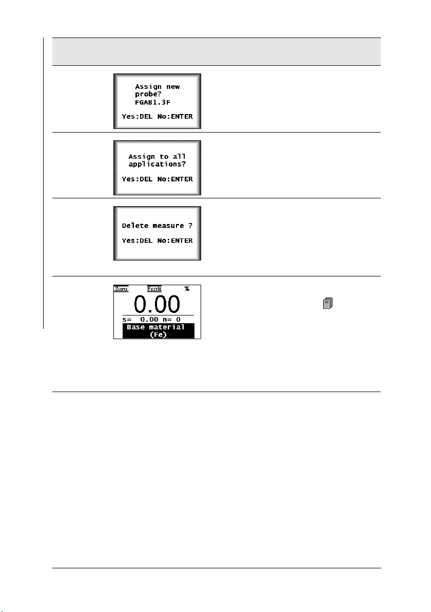
7.
Example: FGAB1.3F = Name of the connected probe
DEL: Probe assignment starts
ENTER: Probe will not be assigned, mea-
surement method display flashes
DEL: Probe will be assigned to all Applications
ENTER: The probe will be assigned only to
the current Application
DEL: All stored readings will be deleted;
the probe will be assigned to the current
Application / all Applications
ENTER: The probe will not be assigned,
measurement method display continues to
flash
ZERO appears on the display.
A normalization is required ( beginning
on Page 68).
[Base material (Fe)]: The measurements
for the normalization should be made on
base.
ENTER: Cancels the normalization.
Page 44 Operators Manual FERITSCOPE® FMP30
Page 47

5 Applications
All relevant settings and parameters for a measuring application as well as the
captured measurement data are stored in a file - we refer to this file as an Application.
The instrument has the capability of setting up up to 100 different Applications.
A maximum of 20,000 readings can be stored in these Applications. The measurements can be combined in up to 4,000 blocks.
Due to the magnetic induction measuring method, which captures
all ferromagnetic components in the same manner, the measurements are always stated in ferrite. No distinction is made between
the different material components, such as ferrite and martensite.
An Application consists of:
z Single readings,
z Application-specific settings, and the
z Coefficients that have been determined during the normalization and
corrective calibration (used for adapting the master characteristic
stored in the probe plug to the current measuring application).
5.1 Setting Up an Application
Applications
A probe must be connected and an application must be set up before measurements can be made in an Application.
From the service function Measurement/Unit ( Page 184), specify the unit of measurement for measuring the ferrite contents of an
Application that is to be set up.
Once the linking mode is enabled (indicated by: on the LCD display),
an automatic check will be carried out to see, whether one or more Applications
have already been set up with the connected probe. If this is the case, no normalization is required when setting up the Application. Instead, the normalization
and corrective calibration of the Application(s) that has/have been set up with this
probe will be used.
Operators Manual FERITSCOPE® FMP30 Page 45
Page 48
Applications
Procedure
As long as the restricted operating mode is enabled (indicated by
on the LCD display), only Applications that have already been
set up can be selected, i.e., it is not possible to set up new Applica-
tions ( 10.6.1 ‘Restricted Operating Mode’, beginning on
Page 171).
Key sequ. /
Action
APPL No Use APPL No to start the selection of the
APPL No Use APPL No to start or continue the se-
∧ or ∨
Detail of the LCD
display
Explanation
Application.
[Appl:]: Application number
[sheet:]: Assigned Application designation
(Example; appears only if an Application
designation has been assigned
( 5.5 ‘Assigning Application Designations’, beginning on Page 52). If an Appli-
cation designation has not been assigned,
the following will appear immediately on
the LCD display:
lection of the Application.
[Appl:]: Application number
[n=]: Number of the measurements stored
in the Application
Use the arrow keys to select an Application that has not yet been set up.
Page 46 Operators Manual FERITSCOPE® FMP30
Page 49

Key sequ. /
Action
ENTER if [always ask] is selected from the service
ENTER Use ENTER to start setting up the Applica-
Detail of the LCD
display
Explanation
function Measurement/Unit
( 10.7.5 ‘Unit’, beginning on Page 184),
select the unit of measurement for making
the measurements in the Application at
this point:
Use the arrow keys to select the unit.
[Fe%]: The ferrite content will be measured in ferrite percent.
[FN]: The ferrite content will be measured
in ferrite numbers.
[OK: ENTER]: Use ENTER to confirm the
selection.
tion.
ZERO appears on the LCD display.
[Base material (Fe)]: The measurements
for the normalization should be made on
base.
Applications
ENTER: Cancels the normalization.
Performing the normalization: begin-
Page 68.
ning on
Operators Manual FERITSCOPE® FMP30 Page 47
Page 50

5.2 Selecting the Desired Application
To make ferrite content measurements, a probe must be connected and an Application must be selected that has been set up using the connected probe before
measurements can be made.
Applications
If [Ferrite] flashes on the LCD Display after instrument power-up or
after selecting an Application, an Application has not yet been set
up using the connected probe. It is not possible to make measurements when the display is flashing.
The following options exist if an Application has not yet been set up using the
connected probe:
z Setting up a new Application using the connected probe ( 5.1 ‘Setting Up
an Application’, beginning on Page 45),
z Overwriting an existing Application using the connected probe
( 5.3 ‘Deleting an Application’, beginning on Page 49),
z Connecting a probe that has already been used to set up an Application
( 3.2 ‘Connecting Probes’, beginning on Page 33).
Procedure Selecting an Application
Key sequ. /
Action
APPL No Use APPL No to start the selection of the
Detail of the LCD
display
Explanation
Application.
[Appl:]: Application number
[n=]: Number of the measurements stored
in the Application
∧ or ∨
Page 48 Operators Manual FERITSCOPE® FMP30
Use the arrow keys to select the desired
Application.
Page 51

Key sequ. /
Action
ENTER Use ENTER to confirm the selected Appli-
Detail of the LCD
display
Explanation
cation. The selected Application will be retrieved. The last reading of the last not
closed block is displayed. The instrument
is ready to make measurements.
5.3 Deleting an Application
As long as the restricted operating mode is enabled (indicated by
on the LCD display), the DEL key will not be enabled, i.e., it is
not possible to delete Applications ( 10.6.1 ‘Restricted Operating
Mode’, beginning on Page 171).
When deleting an Application, all readings as well as the normalization and corrective calibration coefficients stored in the Application
will be deleted. Thus, this Application memory is free for a new measuring application.
Applications
Key sequ. /
Action
APPL No Use APPL No to start the selection of the
∧ or ∨
Operators Manual FERITSCOPE® FMP30 Page 49
Detail of the LCD
display
Explanation
Application.
[Appl:]: Application number
[n=]: Number of the measurements stored
in the Application
Use the arrow keys to select the Application to be deleted or leaf through the pages
using CAL +
∨.
Page 52

Key sequ. /
Action
DEL Use DEL to start the deletion process.
Applications
Detail of the LCD
display
Explanation
Pressing DEL again: Deletes the Application.
ENTER: Cancels the deletion.
It is now possible to select a different Ap-
plication ( Page 48) or to set up a new
Application ( Page 45).
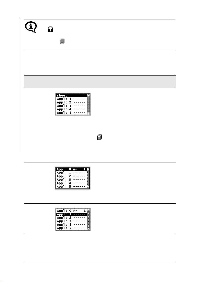
5.4 List of Set Up Applications
Key sequ. /
Action
APPL No Use APPL No to start the selection of the
Page 50 Operators Manual FERITSCOPE® FMP30
Detail of the LCD
display
Explanation
Application.
[sheet]: Assigned Application designation
(Example; appears only if an Application
designation has been assigned
( 5.5 ‘Assigning Application Designations’, beginning on Page 52). If an Appli-
cation designation has not been assigned,
the following will appear immediately on
the LCD display:
[Appl:]: Application number
[n=]: Number of the measurements stored
in the Application
Page 53

Key sequ. /
Action
Print Use PRINT to start the printout of the list of
Detail of the LCD
display
Explanation
set up Applications.
The list of set up applications will print if a
printer is connected and switched on
(Fig. 5-1).
It is now possible to select a different Ap-
plication ( Page 48) or to set up a new
Application ( Page 45).
FISCHER FERITSCOPE FMP30 23.07.08
Applications:
0 sheet
FGAB1.3Fe Fe % 23.07.08 n= 7
1 face
FGAB1.3Fe Fe % n= 3
2 level
FGAB1.3Fe Fe % n= 0
Applications
Fig. 5-1 List of set up Applications (Example
Explanations to Fig. 5-1:
FISCHER FERITSCOPE FMP30
2008-07-23 Current date
0, 1, 2 (1st column) Number of the Application
sheet, face ... Application designation (appears only if an Applica-
FGAB1.3Fe ... Short form designation for the probe that has been
Fe% ... Unit (Fe% or FN)
Operators Manual FERITSCOPE® FMP30 Page 51
Instrument type:
tion designation has been assigned ( Page 52).
used to set up the Application.
Page 54

2008-07-23 End of block - Date of the last block closure of this
Application (if no date is shown, the Application does
not contain a closed block!).
n= Number of measurements stored in this Application
Applications
5.5 Assigning Application Designations
A customer-specific designation that can be comprised of a max. of 16 ASCII
characters can be assigned to every Application.
Assigning the Application designation can be carried out in the following manner:
z Use of the optional software MPNAME (the software is available from your
authorized supplier or directly from the Helmut Fischer GmbH Institute for
Electronics and Metrology.)
z Transmitting the command “SAN” via the USB port ( 9.4.2 ‘Control
Commands’, beginning on Page 142)
When making measurements in the matrix measuring mode, each block can be
assigned a designation as well ( Page 115).
Once Application or block designations have been assigned, the
designations appear in the information lines of the LCD display,
where applicable, alternating with the respective numbers. On printouts, the Application or block designation will appear in place of the
Application or block number.
5.6 Application Specific Settings
The following settings apply only to the settings of the open Application, i.e.,
they are Application-specific:
z Settings that are entered after pressing the MENU key.
z Measurement program ( Page 61)
z Unit ( Page 184)
After pressing the MENU key, the following application-specific settings can be
made:
Page 52 Operators Manual FERITSCOPE® FMP30
Page 55

Key sequ. /
Action
Detail of the LCD
display
Explanation
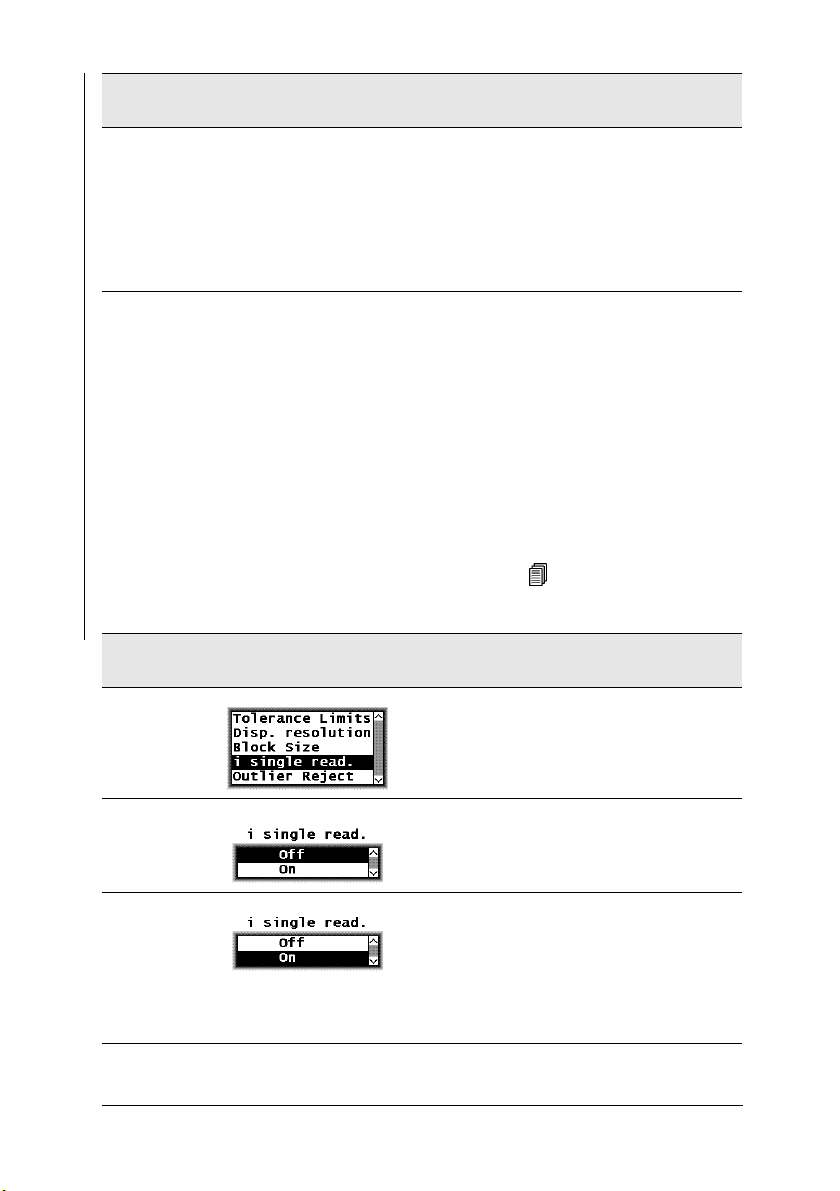
MENU
Selects a menu option by pressing ∧ or ∨:
z Tolerance Limits ( Page 54)
z Measurement display resolution
( Page 56)
z Automatic block size and block creation
( Page 57)
z Number of single readings to be mea-
sured in auto-averaging mode before an
individual value is generated from them
by averaging ( Page 58)
z Outlier rejection ( Page 60)
Pressing ENTER confirms the selection.
Pressing DEL or performing a measurement exits the MENU.
As long as the restricted operating mode is enabled (indicated by
on the LCD display), the MENU key will not be enabled, i.e., it is
not possible to modify these application-specific settings
( 10.6.1 ‘Restricted Operating Mode’, beginning on Page 171)!
Applications
Operators Manual FERITSCOPE® FMP30 Page 53
Page 56

5.6.1 Tolerance Limits
Having the tolerance limits enabled allows for a simple and quick determination
if the measured ferrite contents are within specified limits
( 7.3.5 ‘Measurements With Tolerance Limits Enabled’, beginning on
Page 94).
Applications
Key sequ. /
Action
MENU Use MENU to start Settings.
ENTER Use ENTER to confirm the “tolerance lim-
∧ or ∨
ENTER Use ENTER to confirm the value for the
Detail of the LCD
display
Explanation
its”.
To activate the tolerance limits:
use the arrow keys to select limits “on” or
to deactivate the tolerance limits: Select
limits “off”.
lower specification limit or:
specify a new lower limit by pressing
∧ or
∨.
ENTER
∧ or ∨
Use ENTER to confirm the value for the
upper specification limit or:
specify a new upper limit by pressing
∧ or
∨.
It is also possible to set the upper and lower specification limits by
making a measurement on an object that corresponds approximately to the specification limits to be set.
Page 54 Operators Manual FERITSCOPE® FMP30
Page 57

ENTER Press ENTER to confirm the entry.
The tolerance limits are now set and enabled. Press DEL to return to the measurement screen.
The instrument is ready to make measurements.
Applications
As long as the tolerance limits are enabled,
LCD display.
will appear on the
If the upper and lower specification limits are mixed up when entering the settings, the instrument will automatically select the lower values as the lower specification limit and the higher value as the upper specification limit.
Operators Manual FERITSCOPE® FMP30 Page 55
Page 58

5.6.2 Measurement Display Resolution
The measurement display resolution specifies the resolution for displaying the
readings on the LCD display.
Example: Reading 18.61
Applications
Display with resolution setting “low”:19
Display with resolution setting “standard”: 18.6
Display with resolution setting “high”: 18.61
Resolution 0.0 ...0.999 1.0 ...9.99 10 ...99.99 100 ...999.9 1000 ...9999
low 0.9 9.9 99 999 9999
medium 0.99 9.9 99.9 999 9999
high 999 9.99 99.99 999.9 9999
Key sequ. /
Action
MENU
∨
ENTER
∧ or ∨
ENTER Press ENTER to confirm the selection and
Detail of the LCD
display
Explanation
Use MENU to start Settings and select
“Disp. resolution” using the arrow key
Use ENTER to confirm the selection “Disp.
resolution”.
Use the arrow keys
desired resolution.
return to the menu to enter additional settings.
Press DEL to return to the measurement
screen.
The instrument is ready to make measurements.
∧ or ∨ to select the
∨ .
Page 56 Operators Manual FERITSCOPE® FMP30
Page 59

5.6.3 Automatic Block Size and Block Creation
“Automatic block creation” must be enabled and a block size must be defined for
a certain number of readings to be combined in a block automatically during the
measurement. The block size must be between 2 and 99 ( 7.3.6 ‘Measurements
With a Fixed Block Size’, beginning on Page 94).
Automatic block creation is not available in the matrix measuring
mode.
Applications
Key sequ. /
Action
MENU
∨
ENTER Use ENTER to confirm the selection “Block
∧ or ∨
Enter Press DEL to delete the readings of the
Detail of the LCD
display
Explanation
Use MENU to start Settings.
Press the arrow key ∨, until “Block size” is
highlighted.
size”.
To activate “Block size”:
Use the arrow keys to select Automatic
block result “on” or
to deactivate block size: select Automatic
block result “off”.
open Application.
If measurements have already been made
without a fixed block size, these measurements must be deleted because the subsequent statistical evaluation of the blocks
is correct only if the number of readings is
the same for each block.
When pressing ENTER, the fixed block
size mode will not be enabled.
∧ or ∨
Operators Manual FERITSCOPE® FMP30 Page 57
Use the arrow keys to set the desired block
size.
Page 60
Key sequ. /
Action
ENTER Press ENTER to confirm the selection and
Applications
Detail of the LCD
display
Explanation
return to the menu to enter additional settings.
Press DEL to return to the measurement
screen.
The instrument is ready to make measurements.
The block size can be modified even if automatic block creation has already been
enabled. However, the prompt for deleting previously made measurements will
appear again because the subsequent statistical evaluation does not permit blocks
containing different numbers of readings.
5.6.4 Auto-Averaging Mode
With measurements made in auto-averaging mode, the mean value generated
from a number of single readings is stored in place of the single readings. The
number of single readings must be between 2 and 20 ( 7.3.7 ‘Measurements in
Auto-Averaging Mode’, beginning on Page 96).
Key sequ. /
Action
MENU
∨
ENTER Use ENTER to confirm the selection “i sin-
∧ or ∨
Page 58 Operators Manual FERITSCOPE® FMP30
Detail of the LCD
display
Explanation
Use MENU to start Settings.
Press the arrow key ∨, until “i single read.”
is highlighted on the LCD display.
gle read.”.
To activate the auto-averaging mode:
use the arrow keys to select i single read.
“on” or
to deactivate the auto-averaging mode:
select i single read. “off”.
Use ENTER to confirm the selection.
Page 61

Key sequ. /
Action
Detail of the LCD
display
Explanation
Enter
∧ or ∨
ENTER If the “i” value is modified during a test se-
ENTER Press ENTER to confirm the selection and
If the “i” value is modified during a test series, the prompt to delete
all readings obtained before will appear here as well - for statistical
reasons. If this is not carried out, it will not be possible to modify the
“i” value.
Use Enter to confirm the value for the
number of single readings or:
specify a new value by pressing the arrow
∧ or ∨.
keys
ries, all readings obtained before must be
deleted.
Press ENTER to return to the menu to enter additional settings.
Press DEL to delete all readings of the
open Application.
return to the menu to enter additional settings.
Press DEL to cancel the procedure.
Applications
Operators Manual FERITSCOPE® FMP30 Page 59
Page 62

5.6.5 Outlier rejection
With outlier rejection enabled, recognized outliers will be indicated on the LCD
display and announced through an audible signal ( 7.3.8 ‘Measurements With
Outlier Rejection Enabled’, beginning on Page 97).
The following methods are available for the outlier rejection function:
Applications
z Grubbs Test ( Glossary)
z Specification of a known spread (Sigma) ( Glossary)
Key sequ. /
Action
MENU
∨
ENTER Use ENTER to confirm the selection “Outli-
∧ or ∨
Enter Use ENTER to confirm the method “Auto-
Detail of the LCD
display
Explanation
Use MENU to start Settings.
Press the arrow key ∨, until “Outlier Reject” is highlighted on the LCD display.
er Reject”.
To activate outlier rejection:
use the arrow keys to select Outlier Reject
“on” or
to deactivate outlier rejection:
Select Outlier Reject “off”.
matic”.
or:
∨ Press the arrow key ∨ to specify the
method “Sigma”.
Press the arrow keys to set the desired
Sigma value.
Page 60 Operators Manual FERITSCOPE® FMP30
Page 63

Key sequ. /
Action
ENTER Press ENTER to confirm the selection/en-
Detail of the LCD
display
Explanation
try and return to the menu to enter additional settings.
Press DEL to return to the measurement
screen.
The instrument is ready to make measurements.
5.6.6 Measured Variables
The readings will be displayed on the LCD screen corresponding to the set measured variables.
The following measured variables can be set from the Service function
( 10.7.6 ‘Measured Variable’, beginning on Page 185):
z Fe % or FN (display of the ferrite content in ferrite percent or in ferrite num-
bers),
z normalized countrate X
z Countrate X
z Fe % / FN and Xs
Applications
z Xn and Xs
Explanation of the measured variables: Glossary
The measured variable can be set differently in each Application.
The settings of the measured variables of the other Applications will
not be affected.
With every modification of the measured variable, a prompt for
deleting readings already stored in the open Application will appear
because it is not possible to evaluate different types of measured
variables statistically. This prevents erroneous interpretations of the
measurement results.
Operators Manual FERITSCOPE® FMP30 Page 61
Page 64

Measurement program
Detail of the LCD
display
Explanation
Ferrite con-
Applications
tent
% or FN
Ferrite content display in
[%]: Ferrite percent
[FN]: Ferrite numbers
The ferrite content will be displayed in Fe%
or FN corresponding to the set unit
( 10.7.5).
norm.
countrate
Countrate Displays the countrate X of the measured
Fe % / FN
and Xs
Displays the normalized countrate Xn of
the measured value.
value.
Display of ferrite content and saturation
countrate Xs (countrate for probe in air).
The ferrite content will be displayed in % or
FN corresponding to the set unit
( 10.7.5).
Xn and Xs Displays the normalized countrate Xn of
the measured value and the saturation
countrate Xs.
Page 62 Operators Manual FERITSCOPE® FMP30
Page 65

5.7 Linking Applications
( 10.6.4 ‘Linking Applications’, beginning on Page 177)
If the linking mode is enabled, all applications that have set up using the same
probe (identified by the same serial number) will be linked with each other. Applications that have been linked to each use the same normalization and/or corrective calibration to determine measurements.
Example:
If a separate Application has been set up for each batch of a component (using
the same probe each time), it is useful to link the Applications to each other in
order to compare the Applications to each other. Because these are the same kind
of components, only from different batches, the same normalization and/or corrective calibration should be used every time.
5.7.1 Application Linking Procedure
1.
Enable the instrument function “Linking mode” ( 10.6.4 ‘Linking
Applications’, beginning on Page 177).
2.
Perform a normalization to set up all Applications to be linked. The measurement probe is assigned to the Application ( 5.1 ‘Setting Up an
Application’, beginning on Page 45).
Applications
3.
Perform a careful normalization or calibration on a typical uncoated component ( 6.2 ‘Normalization’, beginning on Page 68 and
6.3 ‘Corrective Calibration’, beginning on Page 71).
This as well as all subsequent normalizations or calibrations will be
applied o all linked Applications; the normalization stored when setting up
the respective Application will be overwritten.
I
Applications that have been set up with different probes of the same
probe model (indicated by the same model designation but different
serial numbers) will not be linked.
Operators Manual FERITSCOPE® FMP30 Page 63
Page 66

5.7.2 Enabling and Disabling the Linking Mode
The linking mode is enabled or disabled from the Service functions of the instrument ( 10.6.4 ‘Linking Applications’, beginning on Page 177).
As long as the linking mode is enabled will appear on the
Applications
LCD display.
After disabling the linking mode, all Applications will again be independent of each other!
Each Application can again be normalized and.or calibrated separately.
5.7.3 Example for Linked Applications
1
2
3
4
Fig. 5-2 Explanation to Fig. 5-3
1 .. Appl 1: Application number
3 .. Serial number of the probe
[%]: Readings are shown in ferrite
percent
2 .. Probe model of the probe that has
been used to set up this Application
Page 64 Operators Manual FERITSCOPE® FMP30
4 .. Norm1: Normalization 1
Cal 1 Corrective calibration 1
Page 67

Applications
Fig. 5-3 Example for linking of applications
Operators Manual FERITSCOPE® FMP30 Page 65
Page 68

Immediately following the linking procedure:
Because a normalization or a corrective calibration has not yet been
carried out immediately following the linking procedure, the normalizations and corrective calibrations of the linked Applications still differ from each other.
Applications
z Applications 4 and 6 are also linked to each other , because they
have been set up with the same FGABW1.3-FE probe (serial number 505).
z Even though Applications 1 and 3 have been set up with the same FGAB1.3-
FE probe (serial number 101), they are not linked to each other because the
readings in Application 1 are displayed in ferrite percent [%] and the readings in Application 3 in ferrite numbers [FN].
z Application 5 is not linked to these two Applications because it has been set
up with the FGAB1.3-FE probe with the serial number 909.
z Application 2 is not linked to any other Application because no other Appli-
cation has been set up with the FGABI1.3_150FE probe (serial number 303).
After the corrective calibration of Application 6:
z Because Applications 4 and 6 are linked with each other, after the correc-
tive calibration of Application 6, the new corrective calibration (Norm 6n,
Cal 6n, grayed out in Fig. 5-3) will be stored in Application 4 as well. The
previous normalization and corrective calibration (Norm 4/6 and Cal 4/6)
will be overwritten.
The normalization and corrective calibration of all other Applications
remains unchanged in spite of linking, because a normalization or
corrective calibration has not yet been carried out with these probes.
Page 66 Operators Manual FERITSCOPE® FMP30
Page 69

6 Normalization, Calibration and Master
Calibration
The following factors influence the readings of a ferrite content measurement:
z Geometry of the specimen (size of the reference area, curvature, distance of
the measurement location from the edge of the specimen, sheet thickness,
cladding thickness)
The correction of these influencing quantities should be carried out based on
the correction factors listed beginning on Page 116.
Creating user-specific calibration standards to determine, for example the influence of the curvature or thickness of the specimen is not
recommended because the ferrite content of the starting material
can be altered even with most careful mechanical processing, especially in the surface area that is registered by the probe.
z Probe tip wear
To a certain degree, probe tip wear can be corrected through a corrective calibration ( beginning on Page 71) or even better, through a master calibra-
tion beginning on Page 77). Too much probe tip wear, which becomes
noticeable through an increased scatter of the readings on a specimen with a
homogeneous ferrite content distribution (e.g., a calibration standard), cannot be corrected. In such a case, the probe must be sent to your authorized
distributor or directly to the Helmut Fischer GmbH Institute for Electronics
and Metrology for repair.
Normalization, Calibration and Master Calibration
6.1 Information Regarding Normalization, Calibration and Master Calibration
z The information in Chapter ““1 ‘Important Information’, beginning on
Page 9“should be observed with every normalization, calibration and master
calibration!
z All measurements should be performed with great care! Only in this manner
can the trueness specified for the used probe be ensured during the subsequent measurements.
Operators Manual FERITSCOPE® FMP30 Page 67
Page 70
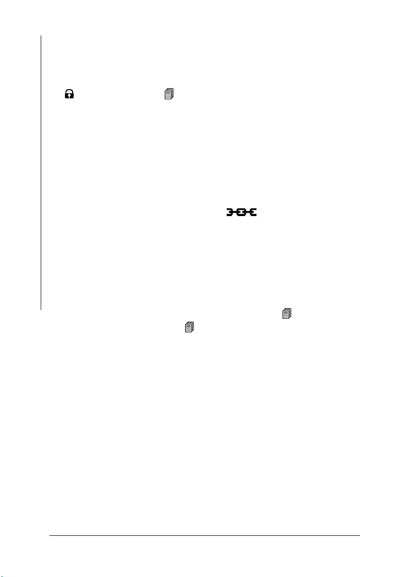
z Reference measurements should be performed after every normalization and
calibration to verify the normalization and calibration.
z It is not possible to start a normalization, corrective calibration or a master
calibration as long as the restricted operating mode is enabled (indicated by
on the LCD display) ( 10.6.1 ‘Restricted Operating Mode’, beginning
on Page 171)!
z A new block starts automatically after every normalization or calibration.
The measurements stored in the Applications will not be deleted after a normalization or calibration. If required, these measurements may need to be
deleted prior to the next measurement.
z The normalization and corrective calibration affects only the open Applica-
tion. The other applications are not affected. The coefficients of the master
characteristic stored in the EEPROM of the probe plug are also not affected.
However, if the linking mode is enabled ( on the LCD display), the
normalization and the corrective calibration affect all Applications that are
linked with the open Application.
z With external start enabled, a measurement acquisition can be triggered dur-
ing a normalization or calibration by:
- Pressing the FINAL-RES key,
- Transmitting one of the ASCII characters “G0”, “ES”, “EN” or
Normalization, Calibration and Master Calibration
- the control character “ESC?” via the USB port (ESC = ASCII27).
Enabling externally triggered measurement acquisition: 10.7.3 ‘External
Start’, beginning on Page 180; 9.4.2 ‘Control Commands’, beginning on
Page 142
6.2 Normalization
With the normalization, a new zero point is established for the calibration curve
of the open Application and stored in the open Application. The coefficients of
the master characteristic stored in the EEPROM of the probe plug are not affected.
Required materials
Base from the calibration standard set
Page 68 Operators Manual FERITSCOPE® FMP30
Page 71

6.2.1 Normalization Procedure
Key sequ. /
Action
ZERO Use ZERO to start the normalization of the
Base
Detail of the LCD
display
Explanation
open Application.
ZERO appears and remains on the LCD
display while the normalization is performed.
[s]: Standard deviation
[n]: Number of measurements
[Base material (Fe]: The measurements
should be made on the base material of
the calibration standard set.
[Cancel: ENTER]: Using ENTER cancels
the normalization.
Make about 5 measurements at different
locations of the base.
The mean value of all readings obtained
for the normalization will be displayed.
[Delete: DEL]: Use DEL to delete the last
measurement DEL, 2x DEL to delete all
readings obtained for the normalization.
[OK: ENTER]: Using ENTER ends the
normalization.
Normalization, Calibration and Master Calibration
ENTER A confirmation indicating that the normal-
ization has been carried out successfully
appears.
Pressing ENTER confirms the message.
PRINT: A print form of the normalization
will be printed if a printer is connected and
switched on ( Page 70).
Operators Manual FERITSCOPE® FMP30 Page 69
Page 72

Key sequ. /
Action
ENTER The new characteristic will be computed
z To verify a correct normalization, perform several reference measurements
Detail of the LCD
display
Explanation
automatically and stored. The instrument
is again ready to make measurements.(
)2.1 ‘LCD-Display’, beginning on
Page 16.
on certified calibration standards. A corrective calibration must be performed if the mean values obtained from several single readings are not
within the guaranteed error limit stated on the calibration standards.
6.2.2 Documenting the Normalization with a Printer
FISCHER FERITSCOPE FMP30 23.07.08
NORMALIZATION 23.07.08 12:38
Appl.No.: 3 Probe: FGAB1.3Fe
Fe
Normalization, Calibration and Master Calibration
fe.= 98.86 Fe% s= 0.321 Fe%
Fig. 6-1 Print form of a normalization (example)
Explanations to Fig. 6-1:
FISCHER FERITSCOPE FMP30
2008-07-23 Current date
NORMALIZATION Normalization will be documented
Date Time Date and time of the normalization
Appl. No. Number of the Application
Probe Probe that has been used to perform the normalization
Fe Applied measurement method
fe. Mean value of all readings obtained for the normalization.
s Standard deviation of the readings obtained for the nor-
Page 70 Operators Manual FERITSCOPE® FMP30
Instrument type:
malization.
Page 73

6.3 Corrective Calibration
With a corrective calibration, a new zero point and one additional point (onepoint calibration with one calibration standard) or two additional points (twopoint calibration with two calibration standards) are established for the calibration curve of the open Application and are stored in the open Application. The
coefficients of the master characteristic stored in the EEPROM of the probe plug
are not affected.
Required materials
z Suitable calibration standard set for the corrective calibration (in the desired
measurement range)
6.3.1 Selecting the Calibration Standards for the Corrective Calibra-
tion
Calibration standards are suitable for corrective calibrations only if their normalized countrates Xn are between the following Xn ranges:
z The normalized countrate Xn of the first calibration standard must be
between 0.02 and 0.9 (0.02 ≤ Xn calibration standard 1 ≤ 0.9).
z The normalized countrate of the second calibration standard (for a two-point
calibration) must be between 0.12 and 0.98 (0.12 < Xn calibration standard 2
≤ 0.98).
z The difference of the normalized countrates of the two calibration standards
that are used for the two-point calibration must be greater than 0.1 (Xn calibration standard 2 - Xn calibration standard 1 = DXn > 0,1).
Determination of the countrate Xn: Page 85.
Operators Manual FERITSCOPE® FMP30 Page 71
Normalization, Calibration and Master Calibration
Page 74

6.3.2 Corrective Calibration Procedure
Key sequ. /
Action
CAL Use CAL to start the corrective calibration
Normalization, Calibration and Master Calibration
Base
Detail of the LCD
display
Explanation
of the open Application.
CAL appears and remains on the LCD display while the corrective calibration is performed.
[s]: Standard deviation
[n]: Number of measurements
[Base material (Fe)]: The measurements
should be made on base.
[Delete cal: DEL]: Using DEL deletes the
corrective calibration ( Page 75).
[Skip: ENTER]: Using ENTER skips the
normalization (the stored normalization is
retained unchanged).
[Cancel: CAL]: Using CAL cancels the
corrective calibration (the stored corrective
calibration is retained unchanged).
Make about 5 measurements at different
locations of the base.
[Delete: DEL]: Use DEL to delete the last
measurement DEL, 2x DEL to delete all
readings obtained for the normalization.
[Cancel: CAL]: Using CAL cancels the
corrective calibration (the stored corrective
calibration is retained unchanged).
[OK: ENTER]: Use ENTER to end and
store the normalization.
Page 72 Operators Manual FERITSCOPE® FMP30
Page 75

Key sequ. /
Action
Detail of the LCD
display
Explanation
ENTER
Calibration standard
[Entry:
rated ferrite content value of the calibration
standard.
The rated value can be set faster if a measurement is performed on a calibration
standard that is within the tolerance range,
and then the rated value is corrected using
the arrow keys.
[CAL-rat. 1: 0.680]: Display of the set rated value for the ferrite content of the calibration standard (Example: 0.680 Fe%)
[Cancel: ENTER]: Using ENTER cancels
the calibration procedure
Make about 5 measurements at different
locations of the calibration standard.
Displayed is the mean value of all measurements performed for this step.
[Delete: DEL]: Use DEL to delete the last
measurement DEL, 2x DEL to delete all
readings obtained for the calibration.
[OK: ENTER]: Use ENTER to end the current calibration step.
∧∨]: Use the arrow keys to set the
Normalization, Calibration and Master Calibration
ENTER If a corrective calibration is desired with 2
or 3 standards, proceed in the same manner with calibration standards 2 and 3.
Otherwise: Use ENTER to end the corrective calibration.
The new characteristic will be computed
automatically and stored.
The instrument is again ready to make
measurements.
Operators Manual FERITSCOPE® FMP30 Page 73
Page 76

Key sequ. /
Action
ENTER A confirmation indicating that the correc-
ENTER The new characteristic will be computed
z To verify a correct calibration, perform several reference measurements on
Detail of the LCD
display
Explanation
tive calibration has been carried out successfully appears.
Pressing ENTER confirms the message.
PRINT: A print form of the corrective calibration will be printed if a printer is con-
nected and switched on ( Page 76).
automatically and stored. The instrument
is again ready to make measurements.(
)2.1 ‘LCD-Display’, beginning on
Page 16.
certified calibration standards. The corrective calibration must be repeated if
the mean values obtained from several single readings are not within the
guaranteed error limit stated on the calibration standards, o if the deviations
are unacceptable again, a master calibration must be performed.
Normalization, Calibration and Master Calibration
Page 74 Operators Manual FERITSCOPE® FMP30
Page 77

6.3.3 Deleting a Corrective Calibration
When deleting the corrective calibration, only the corrective calibration of the open Application will be deleted. The corrective calibrations of the other Applications are retained. However, if the linking
mode is enabled ( on the LCD display), the corrective calibrations of all Applications that are linked with the open Application
will be deleted.
Key sequ. /
Action
CAL Use CAL to start the corrective calibration
DEL [Yes: DEL]: The corrective calibration will
DEL The corrective calibration will be deleted.
Detail of the LCD
display
Explanation
of the open Application.
[Delete cal: DEL]: Using DEL deletes the
corrective calibration.
[Cancel: CAL]: Using CAL cancels the
corrective calibration (the stored corrective
calibration is retained unchanged).
be deleted.
[No: ENTER]: Cancels the delete procedure.
The instrument is again ready to make
measurements.
Normalization, Calibration and Master Calibration
Operators Manual FERITSCOPE® FMP30 Page 75
Page 78

6.3.4 Documenting the Corrective Calibration with a Printer
FISCHER FERITSCOPE FMP30 23.07.08
CALIBRATION 23.07.08 12:43
Appl.No.: 3 Probe:FGAB1.3Fe
Fe
fe.= 104.2 Fe% s= 1.671 Fe%
Measurements on
Base
Fe: 0.680 Fe%
fe.= 0.646 Fe% s= 0.010 Fe%
Fe: 3.08 Fe%
fe.= 3.054 Fe% s= 0.038 Fe%
Fe: 10.90 Fe%
fe.= 10.35 Fe% s= 0.014 Fe%
Fig. 6-1 Print form of a corrective calibration (example)
Explanations to Fig. 6-1:
Normalization, Calibration and Master Calibration
FISCHER FERITSCOPE FMP30
2008-07-23 Current date
CALIBRATION Corrective calibration is being documented
Date Time Date and time of the corrective calibration
Appl. No. Number of the Application
Probe Probe that has been used to perform the calibration
Fe Applied measurement method
Fe: Confirmed rated value for the ferrite content of the calibra-
fe. Mean value of all readings obtained for this step of the
s Standard deviation of the readings obtained for this step
Instrument type:
tion standards.
calibration.
of the calibration.
Measurements on
Calibration standard # 1
Measurements on
Calibration standard # 2
Measurements on
Calibration standard # 3
Page 76 Operators Manual FERITSCOPE® FMP30
Page 79

6.4 Master Calibration
The master calibration determines the coefficients of the master characteristic
and stores them in the EEPROM of the probe plug. These coefficients determine
the master characteristic, i.e., the correlation between the measurement signal of
the probe and the ferrite content.
The EEPROM of the probe plug includes memories for the coefficients of two
master calibrations. These two master calibrations differ in the following manner:
Factory master calibration
One master calibration (factory master calibration) is performed at the facility of
the Helmut Fischer GmbH Institute for Electronics and Metrology with a very
high precision using 5 calibration standards (incl. 1 base). It cannot be deleted or
overwritten by the user.
User Master Calibration
You can set up the user master calibration by yourself using 5 calibration standards. This memory is empty when a new probe is supplied. Once the user has
set up his “own” master calibration in the manner described below, he can overwrite or even deleted this calibration, if needed.
5 calibration standards are required to set up a user master calibration. They are
part of the optional probe-specific master calibration standard set. The Xn values
of one of these calibration standards must be within the prescribed Xn range of
the master calibration for all 4 Xn ranges to be “occupied”.
Normalization, Calibration and Master Calibration
To increase the measuring precision in a certain measurement interval of the
probe, up to 4 additional calibration standards with ferrite contents in this interval
can be used. This means that max. 5 calibration standards can be in an Xn range
of the user master calibration.
If the user master calibration is deleted and an new one is not set up, the factory
master calibration will be used automatically to make measurements.
After setting up or deleting a user master calibration, all corrective
calibrations that have been set up with the respective probe will be
deleted. This means that after deleting the user master calibration
and continued measurements using the factory master calibration, a
new corrective calibration should be performed for each Application,
if necessary.
Operators Manual FERITSCOPE® FMP30 Page 77
Page 80
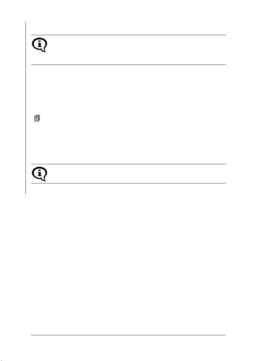
6.4.1 Selecting the Calibration Standards
For the user master calibration, the master calibration standard set available from the Helmut Fischer GmbH Institute for Electronics and Metrology as an option should be used! Only in this manner can the specified
trueness be ensured during the subsequent measurements.
During the user master calibration, the master characteristic can be determined
only if suitable calibration standards are used. If the master calibration standards
of the Helmut Fischer GmbH Institute for Electronics and Metrology are not
used, the normalized countrates Xn of the master calibration standards used in
their place must be within the specific Xn ranges. The Xn values can be displayed
after the 1st step of the user master calibration (normalization)
( 6.4.4 ‘Displaying Xn Ranges for Calibration Standards for the Master Calibration’, beginning on Page 83).
6.4.2 Performing a User Master Calibration
A user master calibration (hereafter simply referred to as a master calibration) must be performed only by experienced users.
Normalization, Calibration and Master Calibration
z The master calibration applies to all Applications that have been set up with
the same probe that has been used for the master calibration (because the
coefficients have been stored in the probe plug of the EEPROM)! This
applies to both an enabled and a disabled linking mode.
z After a master calibration is completed, the normalizations and corrective
calibrations of all Applications that have been set up with the same probe
that has been used for the master calibration will be deleted automatically.
Required materials
z Calibration standard set of the Helmut Fischer GmbH Institute for Electron-
ics and Metrology or
z other suitable certified standards
Page 78 Operators Manual FERITSCOPE® FMP30
Page 81

6.4.3 Master Calibration Procedure
The probe tip should be checked for potential wear prior to a master calibration.
Too much probe tip wear becomes noticeable through an increased
scatter of the readings on a specimen with a homogeneous ferrite content distribution (e.g., a calibration standard).
In such a case, the probe must be sent to your authorized distributor or
directly to the Helmut Fischer GmbH Institute for Electronics and Metrology for repair.
During the master calibration, the master characteristic can be determined only if suitable calibration standards are used.
The calibration standards are suited for the master calibration only if
their normalized countrates Xn are within pre-established Xn ranges.
The limits of the Xn ranges can be queried during the master calibration
without affecting the calibration.
The master calibration is retrieved from the service function menu
( 10.9 ‘Performing a Master Calibration’, beginning on Page 187).
Key sequ. /
Action
5 x ENTER
2 x ∧
Operators Manual FERITSCOPE® FMP30 Page 79
Detail of the LCD
display
Explanation
Press ENTER 5 times to retrieve the “Service Function” menu and set the identification umber 159 of the service functions
using the arrow keys
Retrieve the master calibration from the
Service functions menu and use ENTER to
start the procedure.
∧.
Normalization, Calibration and Master Calibration
Page 82

Key sequ. /
Action
ENTER ZERO + CAL appear and remain on the
If you press DEL again after deleting the master calibration in order to
Normalization, Calibration and Master Calibration
exit the menu, subsequent measurements will be made with the factory
master calibration - without a corrective calibration.
Detail of the LCD
display
Explanation
LCD display while the master calibration is
performed.
[s]: Standard deviation
[n]: Number of measurements
[Base material (Fe)]: The measurements
(normalization) should be made on base.
[MCL Delete: DEL]: Use DEL to delete an
existing master calibration (appears only if
a master calibration has already been performed). Use CAL if you do not wish to delete the master calibration.
[Cancel: CAL]: Use CAL to cancel the
master calibration.
Key sequ. /
Action
Base
Page 80 Operators Manual FERITSCOPE® FMP30
Detail of the LCD
display
Explanation
Make about 5 measurements at different
locations of the base.
The mean value of all readings obtained
for the normalization will be displayed.
[Base material (Fe)]: The measurements
should be made on base.
[Delete: DEL]: Use DEL to delete the last
measurement DEL, 2x DEL to delete all
readings obtained for the normalization.
[OK: ENTER]: Use ENTER to end and
store the normalization. The previous normalization will be overwritten.
Page 83

Key sequ. /
Action
Detail of the LCD
display
Explanation
ENTER
[Entry:
rated ferrite content value of the calibration
standard.
The rated value can be set faster if a measurement is performed on the calibration
standard and then the rated value is corrected using the arrow keys.
[CAL-rat. 1: 680]: Display of the set rated
value for the ferrite content of the calibration standard (Example: 0.680 Fe%)
[Cancel: ENTER]: Using ENTER cancels
the calibration procedure
Pressing FINAL-RES:
Determination of the Normalized Countrate
Xn of a Calibration Standard During a Mas-
ter Calibration Page 85.
Pressing BLOCK-RES:
Displaying Xn Ranges for Calibration Standards for the Master
Calibration Page 83.
Make about 5 measurements at different
locations of the calibration standard.
∧∨]: Use the arrow keys to set the
Normalization, Calibration and Master Calibration
[Delete: DEL]: Use DEL to delete the last
Calibration standard
Operators Manual FERITSCOPE® FMP30 Page 81
measurement DEL, 2x DEL to delete all
readings obtained for the normalization.
[OK: ENTER]: Use ENTER to end and
store the calibration step.
Page 84

Key sequ. /
Action
Detail of the LCD
display
Explanation
∧ or ∨ Use the arrow keys ∧ or ∨ to set the rated
ferrite content value of the calibration standard.
The rated value can be set faster if a measurement is performed on the calibration
standard and then the rated value is cor-
rected using the arrow keys
This step is not required if the rated value
for the ferrite content coincides with the
stored (displayed) value.
[OK: ENTER]: Using ENTER ends the current calibration step.
ENTER Proceed with calibration standard #2 in the
same as described for calibration standard
#1. The same for all subsequent calibration steps.
ENTER After the last calibration step has been
Normalization, Calibration and Master Calibration
concluded using ENTER, the new calibration curve will be computed automatically
and stored, and a confirmation indicating
that the master calibration has been carried out successfully appears.
Pressing ENTER confirms the message.
PRINT: A print form of the master calibration will be printed if a printer is connected
and switched on ( Page 84).
∧ or ∨.
Please note the information regarding the number of calibration stan-
dards under 6.4 on Page 77.
z To verify a correct master calibration, perform several reference measure-
ments.
Now, it is possible to make measurements in the open Application. Delete the
readings of the reference measurement before starting with the measurements on
your specimens.
Page 82 Operators Manual FERITSCOPE® FMP30
Page 85

6.4.4 Displaying Xn Ranges for Calibration Standards for the
Master Calibration
During the master calibration, the master characteristic can be determined only if
suitable calibration standards are used.
The calibration standards are suited for the master calibration only if their normalized countrates Xn are within pre-established Xn ranges. They can be queried
during the master calibration without affecting the calibration.
Key sequ. /
Action
5 x ENTER
2 x ∧
BLOCK-RES Use BLOCK-RES to display the Xn range
BLOCK-RES Use BLOCK-RES to display the Xn range
BLOCK-RES Use BLOCK-RES to display the Xn range
BLOCK-RES Use BLOCK-RES to display the Xn range
Detail of the LCD
display
Explanation
Retrieve the master calibration from the
Service functions menu and use ENTER to
start the procedure. Relevant explanations
beginning on
for calibration standard #1.
[0.0300<Xn<0.2500]: The normalized
countrates Xn of calibration standard #1
must be within these limits of the Xn range.
for calibration standard #2
[0.3000<Xn<0.7000].
for calibration standard #3
[0.5000<Xn<0.0000].
for calibration standard #4
[0.8000<Xn<0.9900].
Page 79.
Normalization, Calibration and Master Calibration
BLOCK-RES Use BLOCK-RES to end the display of the
Xn range.
It is now possible to continue the master
calibration.
Or: Press CAL + DEL to return to the measuring mode.
Operators Manual FERITSCOPE® FMP30 Page 83
Page 86

6.4.5 Documenting the Master Calibration with a Printer
FISCHER FERITSCOPE FMP30 23.07.08
MASTER CALIBRATION 23.07.08 13:34
Appl.No.: 4 Probe: FGAB1.3Fe
Fe
fe.= 104.2 Fe% s= 1.671 Fe%
Measurements on
uncoated specimen
(base material)
Fe: 0.680 Fe%
fe.= 0.646 Fe% s= 0.010 Fe%
Fe: 3.08 Fe%
fe.= 3.054 Fe% s= 0.038 Fe%
Fe: 10.90 Fe%
fe.= 10.35 Fe% s= 0.014 Fe%
Fe: 17.08 Fe%
fe.= 17.034 Fe% s= 0.032 Fe%
Fe: 23.70 Fe%
Normalization, Calibration and Master Calibration
fe.= 23.63 Fe% s= 0.014 Fe%
Fig. 6-2 Print form of a master calibration (example)
Measurements on
Master calibration
standard # 1
Measurements on
Master calibration
standard # 2
Measurements on
Master calibration
standard # 3
Measurements on
Master calibration
standard # 4
Measurements on
Master calibration
standard # 5
Explanations to Fig. 6-2:
FISCHER FERITSCOPE FMP30
2008-07-23 Current date
MASTER
CALIBRATION
Date Time Date and time of the master calibration
Appl. No. Number of the Application
Probe Probe that has been used to perform the calibration
Fe Applied measurement method
Fe: Confirmed rated value for the ferrite content of the calibra-
Instrument type:
Master calibration will be documented
tion standards.
Page 84 Operators Manual FERITSCOPE® FMP30
Page 87

fe. Mean value of all readings obtained for this step of the
calibration.
s Standard deviation of the readings obtained for this step
of the calibration.
6.5 Determination of the Normalized Countrate Xn of a
Calibration Standard During a Master Calibration
The normalized countrate Xn of a calibration standard can be determined as described below during a master calibration without affecting the calibration.
Because FINAL-RES triggers an externally triggered measurement
acquisition if external start is enabled, is not possible to determine the
normalized countrate if external start is enabled during a calibration!
Key sequ. /
Action
FINAL-RES Retrieve the master calibration from the
Calibration stan-
dard
FINAL-RES [off: FINAL-RES]: Use FINAL-RES to re-
Detail of the LCD
display
Explanation
Service functions menu and use ENTER to
start the procedure. Relevant explanations
beginning on
Press FINAL-RES to start the procedure.
Place the probe whose normalized countrate Xn shall is to be determined on the
calibration standard. The normalized countrate Xn of the calibration standard will be
displayed (the normalized countrate will
not be stored!).
turn the free-running display mode to the
disabled state.
It is now possible to continue the calibration.
Page 79.
Normalization, Calibration and Master Calibration
Operators Manual FERITSCOPE® FMP30 Page 85
Page 88

7 Measuring
The information stated in
Measuring
7.1 Preparing for a Measurement
The instrument and the measurement area must be prepared in the following
manner before measurements can be made:
z Agreement on the reference areas (determination on where several single
readings are to be taken), according to DIN EN ISO 2064.
z Ensuring that the reference areas are free of interfering contaminants (e.g.,
moisture, dirt or grease) and are not damaged.
z Carrying Out the System Setup ( Page 29).
z Connecting a printer and if applicable switching it on (if a printer is available
and a printout is desired).
z Switching on the instrument ( Page 37).
Chapter 1 ‘Important Information’, beginning on Page 9
must be observed when making measurements!
z Selecting an Application that is suitable for the specimen ( beginning on
Page 45).
z Determining the instrument configuration ( beginning on Page 147).
z Determining the application-specific settings ( beginning on Page 52).
z Checking the normalization and calibration through measurements on cali-
bration standards.
Page 86 Operators Manual FERITSCOPE® FMP30
Page 89

7.2 Parameters That Influence the Ferrite Content Mea-
surement
The following factors influence the readings of a ferrite content measurement:
z Specimen curvature
z Specimen thickness
z Cladding thickness
z Edge distance of the measurement location
The influence of the specimen's shape can be corrected by multiplying the measured ferrite contents with the respective correction factors ( beginning on
Page 116).
Typically, a correction of these influences is necessary only if
z the curvature diameter of a convex curvature of the specimen is less than 50
mm, or
z the curvature diameter of a concave curvature of the specimen is less than 80
mm, or
z the thickness of the specimen is less than 2 mm, or
z the cladding thickness is less than 2 mm, or
z the distance of the measurement location from the edge is less than 2 mm.
Measuring
For very low ferrite contents, in particular the influence of the thickness
should be determined specific to the measurement application.
7.3 Making a Measurement
To make a measurement, place the probe at a right angle on the specimen surface
( Page 42). The probe can be lifted off after the measurement acquisition, i.e.,
after the reading appears on the display. The instrument is ready to make measurements.
Operators Manual FERITSCOPE® FMP30 Page 87
Page 90

Observe the following during the measurement:
z Measurements should be made within the reference area.
z To avoid erroneous readings, do not allow the probe to hover above the spec-
imen.
Measuring
z To obtain a correct air value, the distance to the specimen should be at least
25 mm.
z To allow sufficient time for a measurement accept, the time between individ-
ual measurements must be greater than 0.5 seconds.
1. Place the probe:
Measurement Object
Fig. 7-1 Measurement using an axial probe
2. Lift the probe off:
1. Place the probe: 2. Lift the probe off:
Measurement Object
Fig. 7-2 Measurement using an angle probe
Page 88 Operators Manual FERITSCOPE® FMP30
Page 91

7.3.1 Measurement Acquisition
As long as automatic measurement acquisition is enabled, measurement acquisition occurs automatically immediately after the probe is placed on the specimen.
An audible signal will sound after the measurement acquisition (unless it has
been disabled) ( 7.3.4 ‘Audible Signals After the Measurement Acquisition’,
beginning on Page 93).
With the “free-running display mode on, measurement acquisition can be triggered in the following manner ( 7.6 ‘Measurements in the Free-Running Display Mode’, beginning on Page 104):
z Pressing the ENTER key
z Transmitting one of the ASCII characters “G0”, “ES”, “EN” or
z Transmitting the control character “ESC?” via the USB port (ESC =
ASCII27)
( 9.4.2 ‘Control Commands’, beginning on Page 142)
Regardless of how the measurement acquisition occurred, the reading will appear
on the LCD display following the measurement acquisition.
Measuring
Operators Manual FERITSCOPE® FMP30 Page 89
Page 92

7.3.2 Measurements With External Start Enabled
When an automatic measurement acquisition is not desired, e.g., when making
measurements in pipes, boreholes or grooves, external start should be enabled
and automatic measurement acquisition disabled (Enabling externally triggered
Measuring
measurement acquisition and disabling automatic measurement acquisition:
Page 180).
Externally triggered measurement acquisition is recommended when the ferrite
content is to be documented in a fixed, pre-specified lateral grid. In this manner,
a measurement is registered even if the ferrite content is too low for an automatic
measurement acquisition, i.e., when it is near or equal to zero.
With external start enabled, the measurement acquisition can be triggered manually in the following ways once the probe is positioned on the measurement location:
z Press the ∧ key
(not with a normalization or calibration)
z Press the FINAL-RES key
(only during a normalization or calibration)
z Transmitting the “ES” command via the USB port
( 9.4.2 ‘Control Commands’, beginning on Page 142)
With externally triggered measurement acquisition, the measurement
acquisition can be delayed by up to 2.5 sec ( 10.7.3 ‘External Start’,
beginning on Page 180)
7.3.3 Automatic Measurement Acquisition
A description of the two acquisition modes will follow under modes for automatic start of measurements after placing the probe). However, both methods will
also work with externally triggered measurement acquisition ( Page 90), but
not in the free-running-mode ( Page 104)!
Measurement Capture Through Area Measurements
With area measurements, the single readings are taken as fast as possible until the
probe is lifted off. Only the determined mean value is stored.
Page 90 Operators Manual FERITSCOPE® FMP30
Page 93

This measuring mode is advantageous if a mean values of the ferrite content distribution is to be determined quickly within a reference area. This mean value is
added to a measurement series as a single reading.
With online output of the single readings via the USB port enabled, only this
mean value will be output as well.
The magnetic poles are subject to increased wear when moving the
probe across a surface.
Measuring
Key sequ. /
Action
Detail of the LCD
display
Explanation
Switch area measurement on from the
menu Service Functions/Measurement/
Measuring Mode ( 10.7.4 ‘Measuring
Mode - Standard/Area Measurement/Auto-
matic Measurement’, beginning on
Page 182) and place the probe on the
specimen.
The LCD displays the symbol for as
long as the probe is on the specimen. In
addition, an audible signal sounds when
the probe is placed on the specimen.
Move the probe with a slight and uniform
pressure across the specimen.
[Appl:]: Application number
[Fe%]: Displays ferrite contents in ferrite
percent (measured variable of the open
Application 10.7.6 ‘Measured Variable’, beginning on Page 185)
[Blck:]: Number of the current block
[n=]: Number of the measurements / block
size stored in the Application
Lift the probe off the specimen.
An audible signal indicates the end of the
measurement.
Operators Manual FERITSCOPE® FMP30 Page 91
Page 94

Measurement Capture Through Automatic Measurements
With automatic measurements, a specified number of readings is taken with a selectable time interval between 2 measurements. In contrast to the area measurement, all single readings will be stored ( Page 90).
Measuring
This measuring mode can be advantageous, for example, when the ferrite content
distribution shall be determined along a line. If the probe is moved by hand or a
suitable mechanical device at a consistent speed along a line, then the measurement points will be at equal distances.
Key sequ. /
Action
Detail of the LCD
display
Explanation
Switch “Autom. Measurement” on from the
menu Service functions/Measurement/
Measuring Mode and select the desired
number of measurements and the time interval of the measurements
( 10.7.4 ‘Measuring Mode - Standard/
Area Measurement/Automatic Measure-
ment’, beginning on Page 182).
Place the probe on the specimen. The
LCD displays the symbol for as long
as the probe is on the specimen.
An audible signal sounds for every measurement that occurred. All measurement
data are evaluated statistically.
Lift the probe off the specimen.
[Appl:]: Application number
[Fe%]: Displays ferrite contents in ferrite
percent (measured variable of the open
Application 10.7.6 ‘Measured Variable’, beginning on Page 185)
[Blck:]: Number of the current block
[n=]: Number of the measurements / block
size stored in the Application
Page 92 Operators Manual FERITSCOPE® FMP30
Page 95
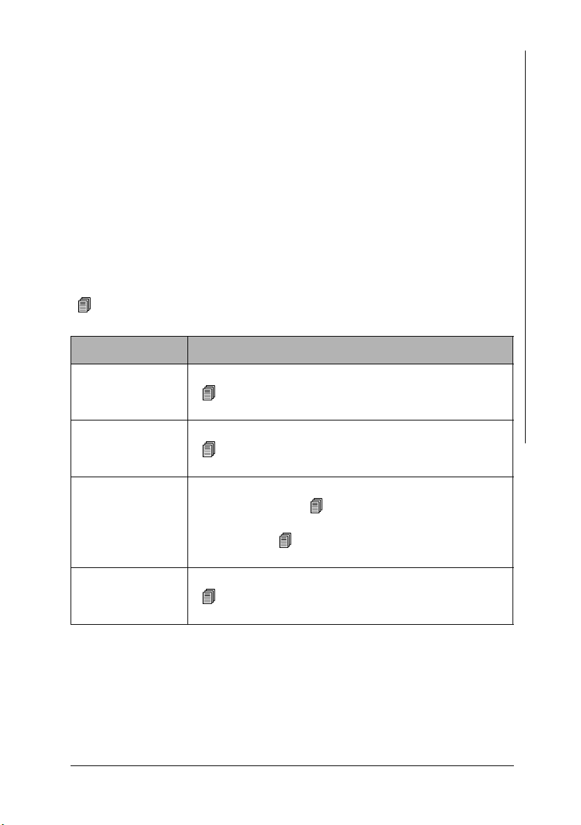
7.3.4 Audible Signals After the Measurement Acquisition
An audible signal will sound after the measurement acquisition (unless it has
been disabled). The measurement acquisition signal indicates that a signal arriving from the probe has been recognized and that the probe can be lifted off the
specimen.
In addition to measurement acquisition signal, the audible signals listed in the
following Table may sound. Where applicable, the signals may sound in succession.
For example, if at a measurement with a fixed block size the last reading of a
block has exceeded the upper specification limit, the measurement acquisition
signal will sound followed by two short signals for exceeding the upper specification limit and one finally a long signal indicating the end of the block.
As an option, the measurement acquisition signal can be disabled
( 10.7.1 ‘Audible Signal’, beginning on Page 178).
The other audible signals cannot be disabled!
Signal Meaning
1 x short Measurement below lower specification limit.
( 7.3.5 ‘Measurements With Tolerance Limits Enabled’, beginning on Page 94)
2 x short Upper specification limit is exceeded.
( 7.3.5 ‘Measurements With Tolerance Limits Enabled’, beginning on Page 94)
1 x long The block was concluded automatically and the block re-
sult was generated ( 7.3.6 ‘Measurements With a
Fixed Block Size’, beginning on Page 94) or the block
was changed ( 10.6.3 ‘Matrix Mode’, beginning on
Page 174“)
2 x long The measurement was recognized as an outlier
( 7.3.8 ‘Measurements With Outlier Rejection Enabled’,
beginning on Page 97).
Measuring
Operators Manual FERITSCOPE® FMP30 Page 93
Page 96

7.3.5 Measurements With Tolerance Limits Enabled
Having the tolerance limits enabled allows for a simple and quick determination
if the measured ferrite contents are within specified limits ( Page 54).
Measuring
As long as the tolerance limits are enabled, will appear on the LCD
display.
Detail of the LCD
display
Explanation
After a measurement is taken that violates the lower
specification limit, appears in front of the reading on
the LCD display. In addition, a brief audible signal
sounds after the measurement acquisition to indicated
the violation of the tolerance limit.
After a measurement is taken that violates the upper
specification limit, appears in front of the reading on
the LCD display. In addition, two brief audible signals
sound after the measurement acquisition to indicate the
violation of the tolerance limit.
If the measurement acquisition signal has been disabled, only the signal, or the
signals, for violating the tolerance limits will sound.
With outlier rejection enabled, the audible signals indicating an outlier measurement will sound when an outlier is recognized. In this case, the violation of the
tolerance limit will not be indicated acoustically.
7.3.6 Measurements With a Fixed Block Size
When making measurements with a fixed block size,
z the block creation is carried out automatically after an adjustable number of
measurements has been performed by the instrument (Setting the Block
Size: Page 57).
z appears on the LCD display after the last measurement of the block has
been taken, and
Page 94 Operators Manual FERITSCOPE® FMP30
Page 97

z the closure of the block is indicated by a long audible signal (if the measure-
ment acquisition signal has been disabled, only the signal to indicated the
block closure will sound).
With a connected and powered up printer, it is now possible to print the block result automatically after the block closure or upon ( 10.5.4 ‘Block Result’, beginning on Page 167).
Measuring
Key sequ. /
Action
Detail of the LCD
display
Explanation
Make a measurement. The reading will appear on the LCD display.
[Appl:]: Application number
[Fe%]: Displays ferrite contents in ferrite
percent (measured variable of the open
Application 10.7.6 ‘Measured Variable’, beginning on Page 185)
[Blck:]: Number of the current block
[n=]: Number of the measurements / block
size stored in the Application
Perform the number of measurements required for an automatic block closure.
[]:Block is closed; no more measure-
ments can be taken in this particular block.
A new blocks starts automatically when the
next measurement is taken.
Individual readings / erroneous measurements can be overwritten in a
closed block ( 7.5.4 ‘Overwriting Individual Erroneous Measurements
at a Later Time’, beginning on Page 102).
Operators Manual FERITSCOPE® FMP30 Page 95
Page 98

7.3.7 Measurements in Auto-Averaging Mode
With measurements made in auto-averaging mode, the mean value generated
from a number of single readings is stored in place of the single readings. Thus,
this mode is particularly well suited for rough surfaces.
Measuring
(For setting the number of single readings from which the average of the readings
to be stored is determined: 5.6.4 ‘Auto-Averaging Mode’, beginning on
Page 58)
In the auto-averaging mode and with outlier rejection enabled, the single readings
that are recognized as outliers will not be integrated in the measurement calculation! For example, if an outlier is recognized at i = 5, only the 4 remaining readings will be used to generate the mean value.
Key sequ. /
Action
Detail of the LCD
display
Explanation
Make a measurement. The reading will appear on the LCD display.
[Appl:]: Application number
[i=]: Number of single readings measured /
set number of single readings to be combined
[Blck:]: Number of the current block
[n=]: Number of the measurements stored
in the Application
Perform the number of measurements required for the number of stored measurements to be increased by one ([i=0/n] will
be displayed.) The mean value of the performed single readings will be displayed
and stored.
Page 96 Operators Manual FERITSCOPE® FMP30
Page 99

7.3.8 Measurements With Outlier Rejection Enabled
When making measurements with outlier rejection enabled:
z the outlier measurements recognized by the instrument will appear on the
LCD display and will be indicated acoustically ( 5.6.5 ‘Outlier rejection’,
beginning on Page 60),
Measuring
Detail of the LCD
display
Explanation
z
and will appear in front of the reading on the
LCD display after a measurement has been taken that
has been recognized by the instrument as an outlier,
z two long audible signals will sound to indicated the outlier measurement in
addition to the audible signal for the measurement acquisition,
z recognized outliers will not be integrated in the evaluation of the current
block or the current Application.,
z only the signals for indicating the outlier measurements will sound if the
measurement acquisition signal has been disabled,
z outlier measurements recognized in the auto-averaging mode will not be
integrated in the measurement calculation, and
z only the audible signals indicating an outlier measurement will sound when
an outlier is recognized (a violation f the tolerance limits will not be indicated).
Detail of the LCD
display
Explanation
Outlier! appears briefly in the information lines of the
LCD display in addition to the audible signal if a past
reading with the number n (in the example, n = 1) is recognized as an outlier measurement (thereafter, the measurement just taken will appear).
Operators Manual FERITSCOPE® FMP30 Page 97
Page 100

7.4 Documenting the Measurement with a Printer
With a connected and powered up printer, it is possible to print individual readings by pressing the PRINT key
( Fig. 7-3 and Fig. 7-4). [Print single readings on] must be set from the
Measuring
Service Functions/Print menu ( 10.5.3 ‘Print Individual Single Readings’, beginning on Page 166).
Application No. 3 Block No.: 1
n= 1 fe = 10.8%
n= 2 fe = 10.8%
n= 3 fe = 10.8%
n= 4 fe = 10.8%
n= 5 fe = 3.1%
n= 6 fe = 10.8%
n= 7 fe = 10.8%
Fig. 7-3 Printout of the readings (example)
If tolerance limits are enabled when making measurements, the readings will be
entered between or next to the tolerance limits on the printout ( Fig. 7-4).
Measurement
below lower
n LSL USL
10.8% 11.0%
1|<<| | | 10.8
2| |* | | 10.8
3| |* | | 10.8
4| |* | | 10.8
5|<<| | | 3.1
6| |* | | 10.8
7|<<| | | 10.8
Fig. 7-4 Printout of the reading with tolerance limits (example)
For measurements in auto-averaging mode, only the mean value computed from
the single readings will be printed and stored. The individual readings are not
stored.
Page 98 Operators Manual FERITSCOPE® FMP30
Application No. 3 Block No.: 1
 Loading...