

Page 1

D
Fahrradträger »Dachlift«
– für den sicheren liegenden Transport von zwei Fahrrädern –
Originalbetriebsanleitung Art.-Nr.: 18092 Stand 02/2015
Inhalt
1. Sicherheitshinweise ....................................................................................... 2
2. Bestimmungsgemäßer Gebrauch ................................................................ 3
3. Werkzeug für den Zusammenbau ................................................................ 3
4. Teileliste Dachlift-Fahrradträger .................................................................. 4
5. Allgemeine Vorab-Informationen ................................................................. 7
6. Zusammenbauen ........................................................................................... 9
7. Service, Hersteller ........................................................................................ 20
Dach
GB
Bicycle rack »Roof lift« .........................................................
– for safe transport of two bicycles in horizontal position –
F
Porte-vélos avec aide au »levage sur le toit« .....................
– pour le transport sûr et couché de deux bicyclettes –
IT
Portabici »Tetto auto« ........................................................... 61
– per il trasporto sicuro di 2 biciclette in posizione orizzontale –
PL
Bagażnik na rowery »Dachowego bagażnika« ...................
– do bezpiecznego przewożenia maks. dwóch rowerów (w pozycji leżącej) –
18092_Betriebsanleitung_D_GB_F_IT_PL.indd 1 13.02.15 11:25
21
41
81
Page 2

Sehr geehrte Kunden,
Vielen Dank, dass Sie sich für den FISCHER Dachlift-Fahrradträger entschieden haben.
Mit diesem Dachlift-Fahrradträger können Sie einfach und sicher zwei Fahrräder liegend
mit Ihrem PKW transportieren. Dieser Dachlift-Fahrradträger wird als Bausatz geliefert.
Sie müssen diesen Dachlift-Fahrradträger vor der ersten Verwendung sorgfältig anhand
dieser Betriebsanleitung montieren.
1. Sicherheitshinweise
HINWEIS: Lesen Sie unbedingt diese Betriebsanleitung sorgfältig durch, bevor Sie mit der
Montage des Dachlift -Fahrradträgers beginnen! Beachten Sie besonders die Sicherheitshinweise!
• Betriebsanleitung während der Lebensdauer des Produktes aufbewahren
• Betriebsanleitung an die nachfolgenden Besitzer und Nutzer des Produktes weitergeben
WICHTIG: Beachten Sie die Angaben Ihres PKW-Herstellers zur höchstzulässigen Dachlast.
Dieser Fahrradträger wurde mit Sorgfalt und entsprechend den Sicherheitsvorschriften der Norm
entwickelt, gebaut und geprüft.
Warnung
• Verschraubungen regelmäßig vor Fahrtantritt kontrollieren.
• Nach 10 km Fahrt und dann in regelmäßigen Abständen Befestigungen des Trägers und der
Fahrräder überprüfen.
• Fahrweise und Geschwindigkeit dem Transport anpassen. Da sich das fahrdynamische Verhalten bei Fahrzeugen mit beladenem Dachträger stark verändert müssen wir empfehlen, die
maximale Höchstgeschwindigkeit von 130 km/h nicht zu überschreiten. Für Schäden, die in
Extrem situationen wegen überhöhter Geschwindigkeit auftreten, kann keine Haftung übernom-
men werden.
• Leerfahrten vermeiden! Wenn keine Fahrräder transportiert werden, Träger demontieren.
• Laut STVO ist der Fahrer für die ausreichende Sicherung der Ladung verantwortlich.
• Eigengewicht des Fahrradträgers: 13,8 kg; maximale Beladung mit zwei Fahrrädern (je 15 kg).
• Beachten Sie unbedingt die Tragfähigkeit des Grundträgers.
Tragkraft = Fahrradträger + Fahrräder
• Die Angaben des Fahrzeugherstellers über die zulässige Dachlast sind unbedingt zu beachten.
Dachlast = Grundträger + Fahrradträger + Fahrräder.
• Beachten Sie die veränderte Gesamthöhe des Fahrzeuges insbesondere bei niedrigen Durchfahrtshöhen (Garagen, Tiefgaragen, Brücken). Aufbauhöhe auf Grundträger ca. 60 cm.
• Träger und Fahrräder dürfen nicht über den Umriß des Fahrzeuges ragen.
• Zu Ihrer Sicherheit beim Be- und Entladen der Fahrräder empfehlen wir den Träger so zu montieren, daß er auf der Beifahrerseite abgesenkt werden kann.
• Ersatzschlüssel für abschließbares Handrad an getrenntem Ort gut aufbewahren.
• Bewahren Sie die Montageanleitung auf.
• Bei Nichtbeachtung der Montageanweisungen und Sicherheitshinweise und daraus folgenden
Schäden an Fahrzeug und/oder Fahrrädern wird jegliche Haftung seitens des Vertreibers und
des Herstellers abgelehnt.
2
18092_Betriebsanleitung_D_GB_F_IT_PL.indd 2 13.02.15 11:25
Page 3

2. Bestimmungsgemäßer Gebrauch
Der Dachlift-Fahrradträger dient zum Transport von zwei Fahrrädern auf dem Dach eines PKW.
Der Dachlift-Fahrradträger muss entsprechend dieser Betriebsanleitung zusammengebaut
werden. Im Fahrbetrieb müssen die entsprechenden gesetzlichen Bestimmungen (erlaubte
Höchstgeschwindigkeit, höchst zulässiges Gesamtgewicht, etc.) eingehalten werden.
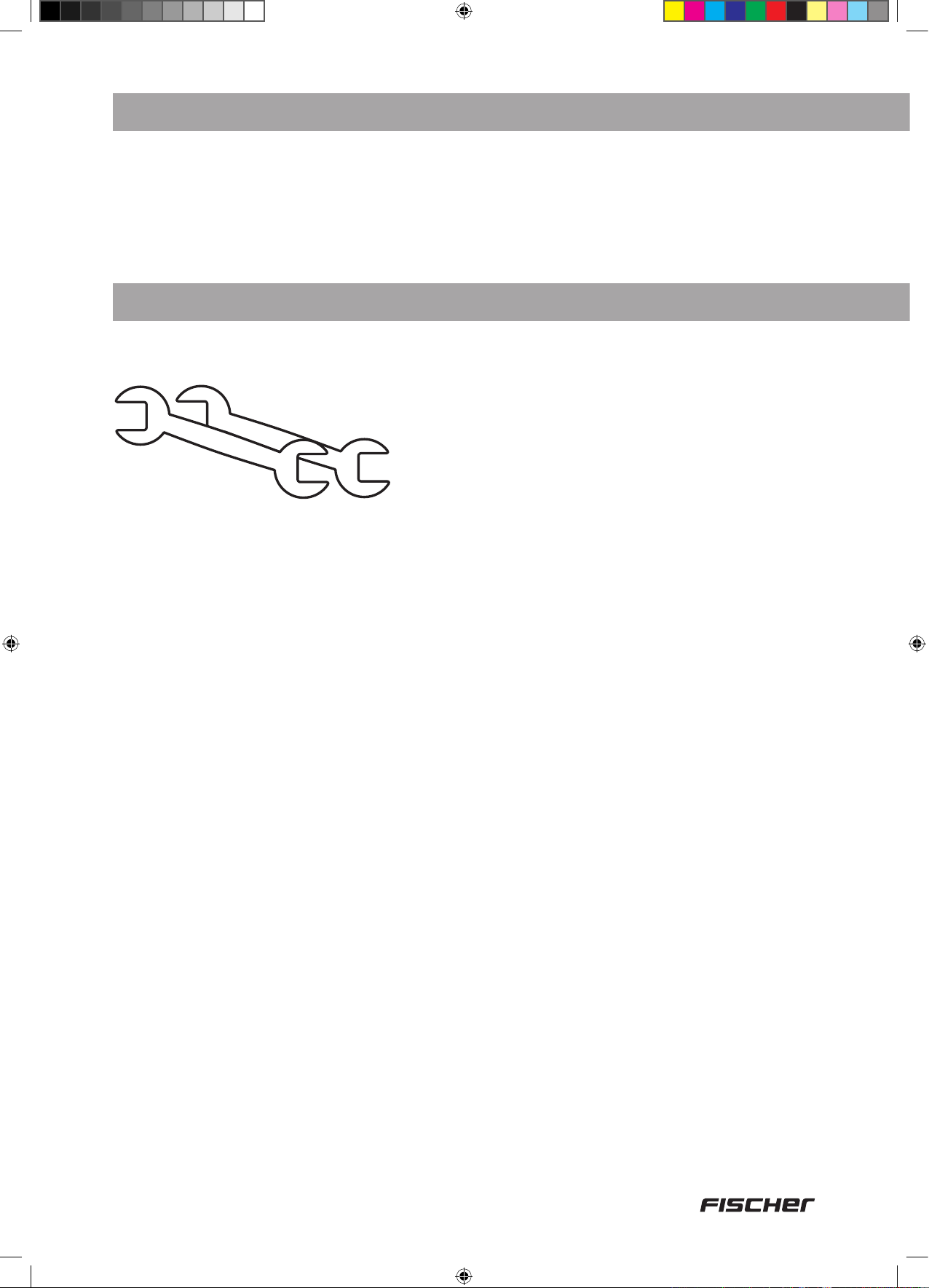
3. Werkzeug für den Zusammenbau
Für den Zusammenbau benötigen Sie folgendes Werkzeug:
2 x Ø 10 mm
3
18092_Betriebsanleitung_D_GB_F_IT_PL.indd 3 13.02.15 11:25
Page 4
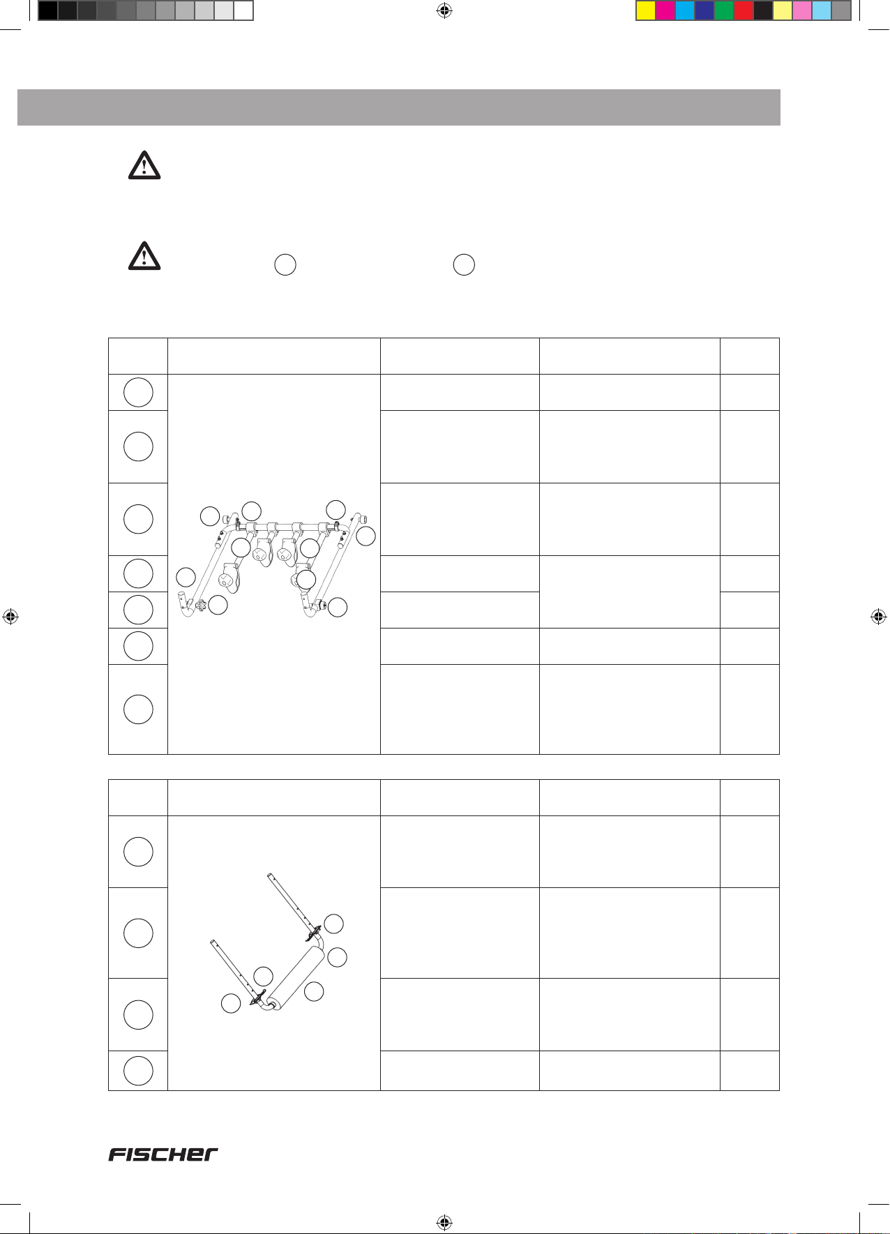
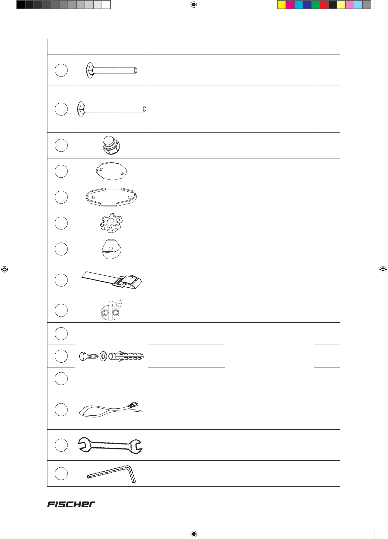
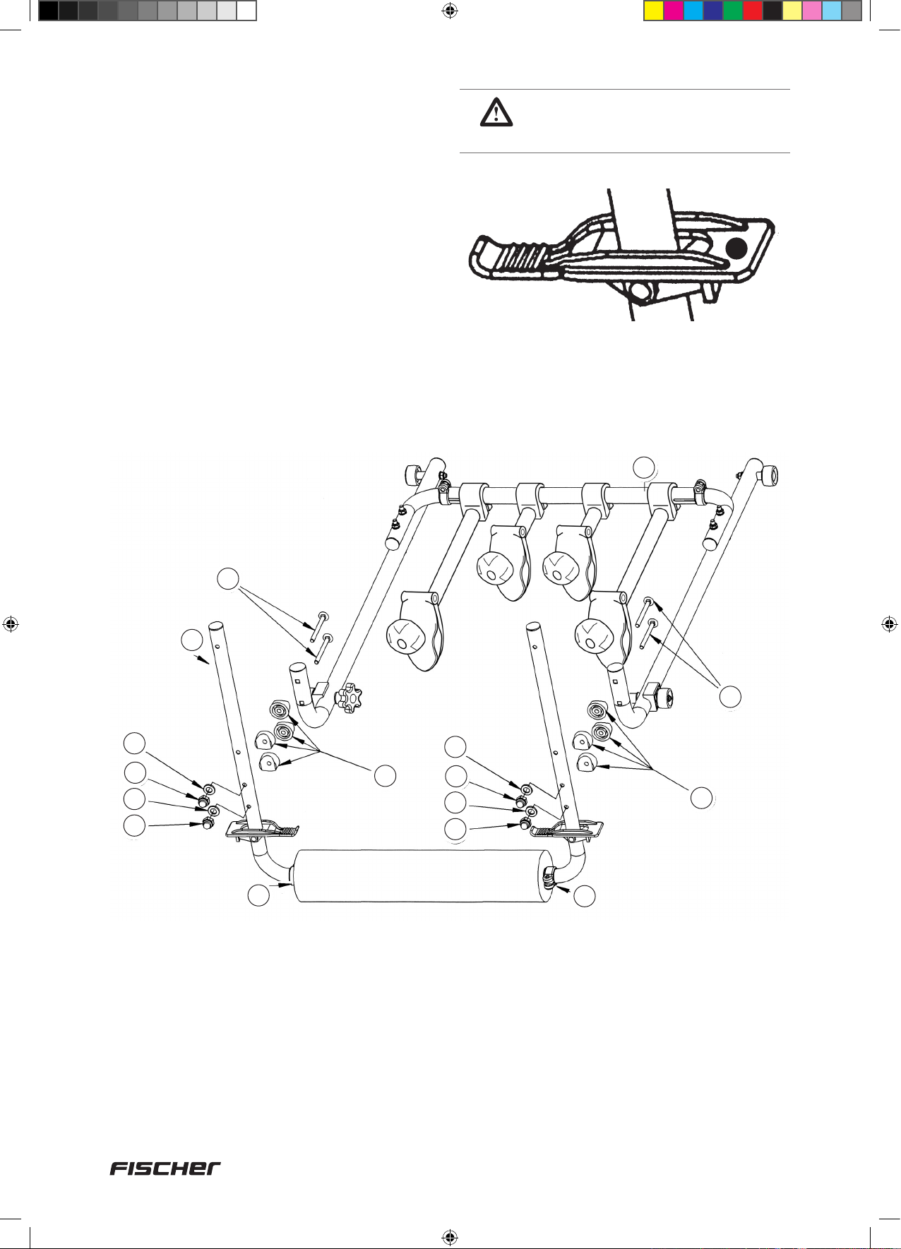
4. Teileliste Dachlift-Fahrradträger
Achtung: Wenn Sie mit diesen Einzelteilen arbeiten, achten Sie darauf, dass
keine Kleinkinder in der Nähe sind. Der Dach-Fahrradträger enthält Kleinteile,
die verschluckt werden können!
Basiseinheit
Teile Nr. Abbildung Bezeichnung Funktion / Verwendung Anzahl
1
1a
1b
1d
1e
1a
+ Fahrrad-Tragebügel
1
1e
1b
1d
Basiseinheit
Fahrrad-Haltearm
290 mm,
1× abschließbar
Fahrrad-Haltearm
100 mm
= Trageeinheit
2
Befestigung äußeres
Rad (vormontiert an
Basiseinheit)
Befestigung inneres
Rad (vormontiert an
Basiseinheit)
1
2
2
1c
1d
1e
1f
Teile Nr. Abbildung Bezeichnung Funktion / Verwendung Anzahl
1c
1f
1f
1c
2
2a
2a
2c
2b
2a
2c
2b
Führungsrolle vorne Führung Basiseinheit
in Führungsschienen
Führungsrolle hinten
Schellen Breiteneinstellung
Handrad
FahrradTragebügel
Sicherungsklammer
Schaumstoff-
Prol
(vormontiert)
Sicherung der Basiseinheit in Führungs-
schienen, vormontiert
an Basiseinheit
Aufnahme Fahrräder
(Montage an Basiseinheit)
Zusatzsicherung für Trageeinheit (vormontiert
an Basiseinheit) mit „L“
und „R“ gekennzeichnet
Polsterung an Fahrzeugseite (vormontiert an
Fahrrad-Tragebügel)
2
2
2
2
1
2
1
2c
Schellen Breiteneinstellung
2
4
18092_Betriebsanleitung_D_GB_F_IT_PL.indd 4 13.02.15 11:25
Page 5
Teile Nr. Abbildung Bezeichnung Funktion / Verwendung Anzahl
3
3a
3b
3c
Teile Nr. Abbildung Bezeichnung Funktion / Verwendung Anzahl
4
4a
Die Stützrolle (3a)
liegt rechts
3b
3a
Die Stützrolle (4a)
liegt rechts
4a
4b
3c
4c
Führungsschiene
links
Stützrolle
Grundplatte vorne Auage auf Grund-
Grundplatte hinten
Führungsschiene
rechts
Stützrolle
Führung Trageeinheit /
Montage auf Grundträger
Führung der ausgezogenen Trageeinheit
(vormontiert an
Führungsschiene)
träger (vormontiert an
Führungsschiene)
Führung Trageeinheit /
Montage auf Grundträger
Führung der ausgezogenen Trageeinheit
(vormontiert an
Führungsschiene)
1
2
1
1
1
2
4b
4c
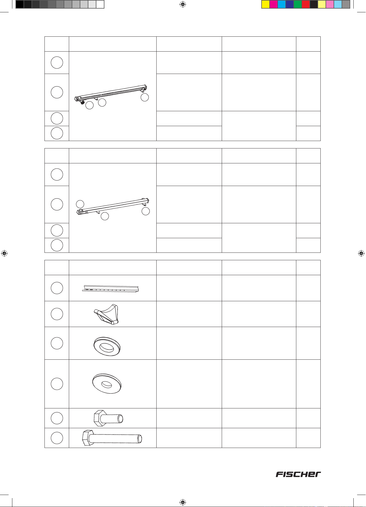
Teile Nr. Abbildung Stückbeschreibung Funktion/ Verwendung Anzahl
5
6
7
8
Grundplatte vorne
Grundplatte hinten
FahrradProlschiene
750 mm
Schutzkappe für
Fahrrad-Prolschiene
Unterlegscheibe,
6,5 mm, klein
Unterlegscheibe,
6,5 mm, groß
Auage auf Grundträger (vormontiert an
Führungsschiene)
Aufnahme der Fahrräder,
Montage an Fahrrad-
Tragebügel
Kantenschutz für
Prolschiene, Montage
an Fahrrad-Prolschiene
Montage Fahrrad-Prolschiene an Trageeinheit (4×)
Montage Fahrrad-Tragebügel an Basiseinheit (4×)
Verbindung Fahrrad-Prolschienen (8×) Montage
Fahrrad-Prolschiene an
Trageeinheit (4×) Montage
Führungsschienen auf
Grundträger (8×)
1
1
4
4
8
20
9
10
Schraube M6 × 16 mm
Schraube M6 × 35 mm
Verbindung FahrradProlschienen
Montage Fahrrad-Prolschiene an Trageeinheit
4
4
5
18092_Betriebsanleitung_D_GB_F_IT_PL.indd 5 13.02.15 11:25
Page 6

Teile Nr. Abbildung Stückbeschreibung Funktion/ Verwendung Anzahl
11
12
13
14
15
16
Schlossschraube
M6 × 50 mm
Schlossschraube
M6 x 70 mm
Hutmutter M6
Befestigungsplatte
Schutzprol für
Befestigungplatte und
Grundplatte
Rändelmutter M6
Montage Führungsschiene
auf Grundträger mit Barrenhöhe bis 35 mm
Montage Fahrrad-Tragebügel
an Basiseinheit (4
Montage Führungsschiene
auf Grundträge mit Barrenhöhe größer als 35 mm (8
Schraubverbindungen
(außer bei Führungsschiene)
Montage an Unterseite
Grundträger
Montage an
Befestigungsplatte
Befestigung Führungsschiene auf Grundträger
×
)
×
)
8
12
12
4
8
8
17
18
19
20a
20b
20c
21
Abstandhalter
Fahrrad-Sicherungs-
gurt, 330 mm
Haken Aufhängung Trageeinheit
Dübel, 6 mm
Schraube M6 × 45 mm
Unterlegscheibe 6,5 mm
Fahrrad-Sicherungsgurt, 5 m
Montage zwischen FahrradTragebügel und Basiseinheit
Sicherung Fahrräder auf
Prolschienen Montage an
Fahrradfelgen und Prol-
schiene
Befestigung Haken (19)
Verbindung FahrradProlschienen
Sicherung Fahrräder auf
Prolschienen
8
8
2
4
4
4
1
Für alle Schraubverbindungen am Fahrradträger
(Schlüsselweite 10 mm)
Für Einstellung der
Auschlagpuffer
1
1
22
23
Doppelmaulschlüssel,
10/13 mm
Inbus-Schlüssel, 5 mm
6
18092_Betriebsanleitung_D_GB_F_IT_PL.indd 6 13.02.15 11:25
Page 7

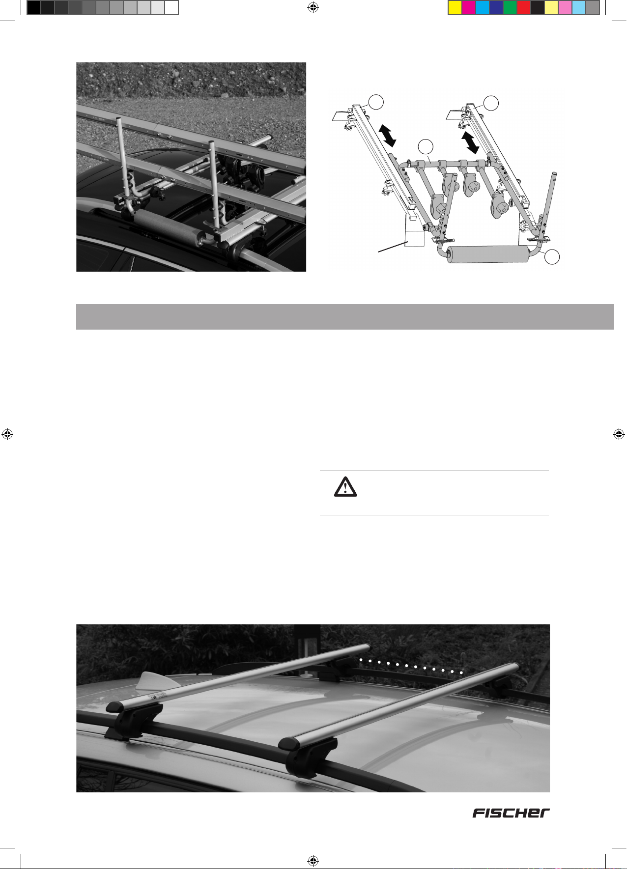
Die Trageeinheit kann in den Führungsschienen
(3+4) nach vorne und nach hinten verschoben
werden.
3
1
4
Grundträger
5. Allgemeine Vorab-Informationen
Schritt 1
Der Grundträger – Voraussetzung für die einwandfreie Funktion des
Dachlift-Fahrradträgers
Zunächst muss der Grundträger auf das
Fahrzeugdach montiert werden.
Unbedingt Beachten!
Beide Tragebarren müssen parallel zueinander
und im gleichen Abstand montiert werden
Bei vielen Fahrzeugen sind die Montagepunkte
vom Fahrzeughersteller durch Markierungen
fest vorgegeben.
Bei Fahrzeugen z.B. mit Regenrinne oder Dachreling sind keine fixen Punkte vom Hersteller
vorgesehen. Hier soll der Barrenabstand mind.
70 cm jedoch max. 87 cm betragen.
Hinweis: Benutzen Sie ein Metermaß um die
Barren abstände zu kontrollieren.
Abstand mindestens 70 cm, maximal 87 cm
WICHTIG! Tragebarren parallel
in gleichen Abstand montieren.
2
70 – 87 cm
7
18092_Betriebsanleitung_D_GB_F_IT_PL.indd 7 13.02.15 11:25
Page 8
Schritt 2
Vorbereitung des Trägers für die Montage, Trennung der Basis einheit (1) von den
Führungsschienen (3+4)
Bei Lieferung ist die Basiseinheit (1) zum Schutz
der Führungsrollen (1c+1d) in die Führungsschienen eingeschoben. Vor der Montage auf
das Fahrzeug müssen Basiseinheit und Führungs-
schienen getrennt werden.
1. Handrad (1f) links und rechts lösen
(nicht vollständig abdrehen!)
2. Führungsschienen (3+4) nach hinten drü-
cken, bis vordere Führungsrolle (1c) in der
Öffnung der Schiene anschlägt und durch
die Öffnung nach oben aushängen.
3. Führungsschiene (3+4) weiter nach hinten
drücken, bis hintere Führungsrolle (1d) in
der Öffnung der Schiene anschlägt und
Basiseinheit durch die Öffnung nach oben
aushängen.
1
3
1f
drücken
4
2
3
8
18092_Betriebsanleitung_D_GB_F_IT_PL.indd 8 13.02.15 11:25
Page 9

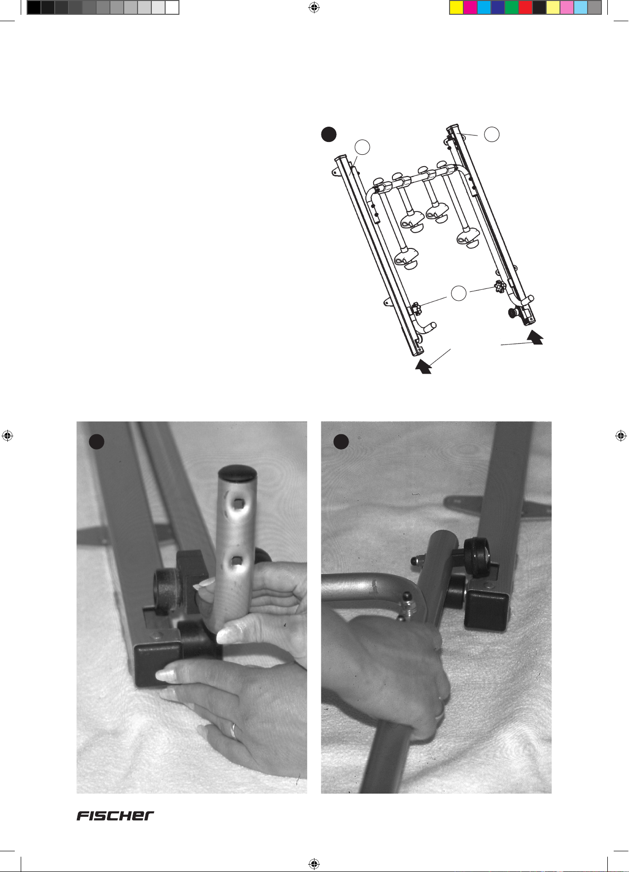
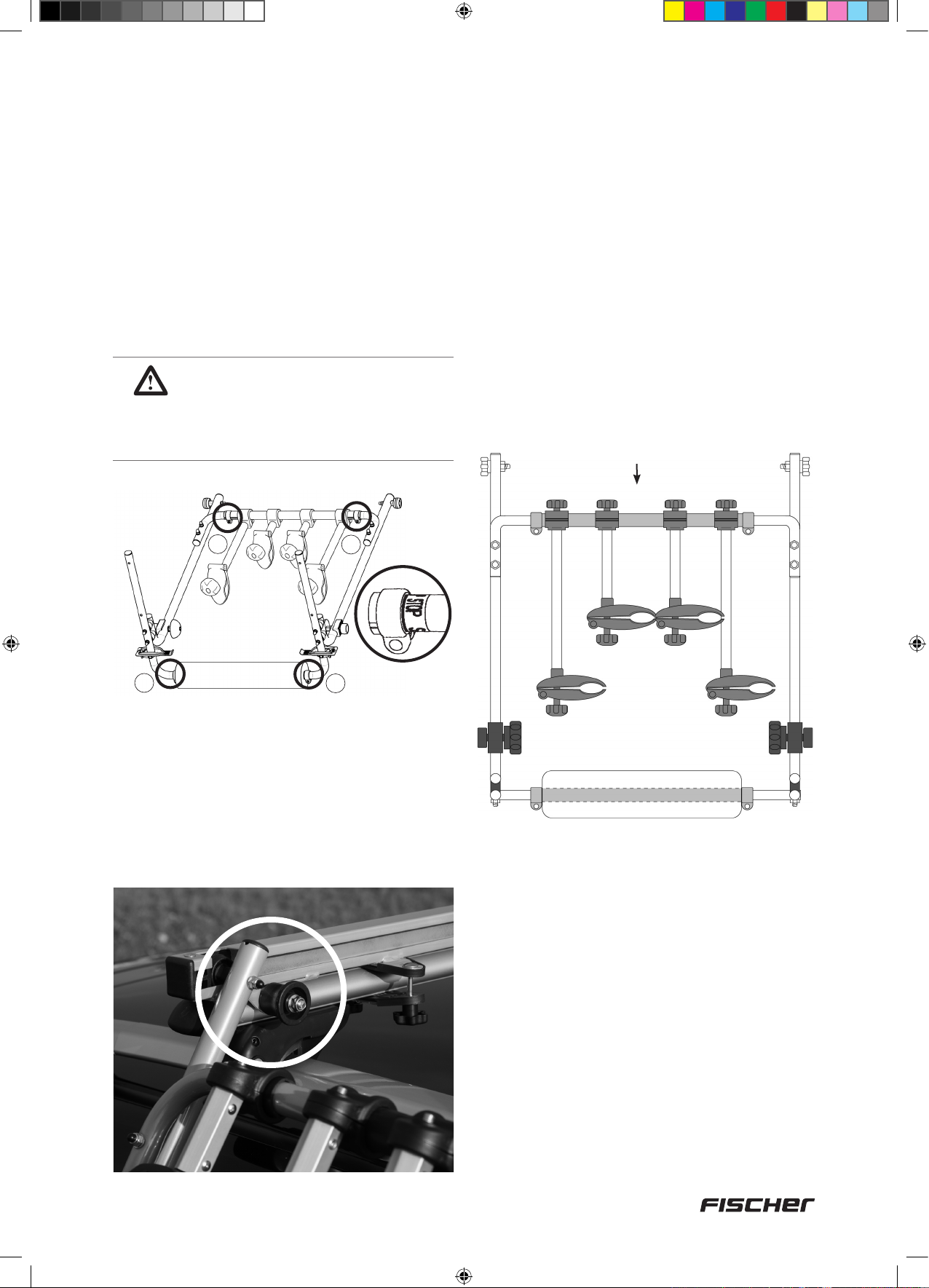
6. Zusammenbauen
Schritt 3
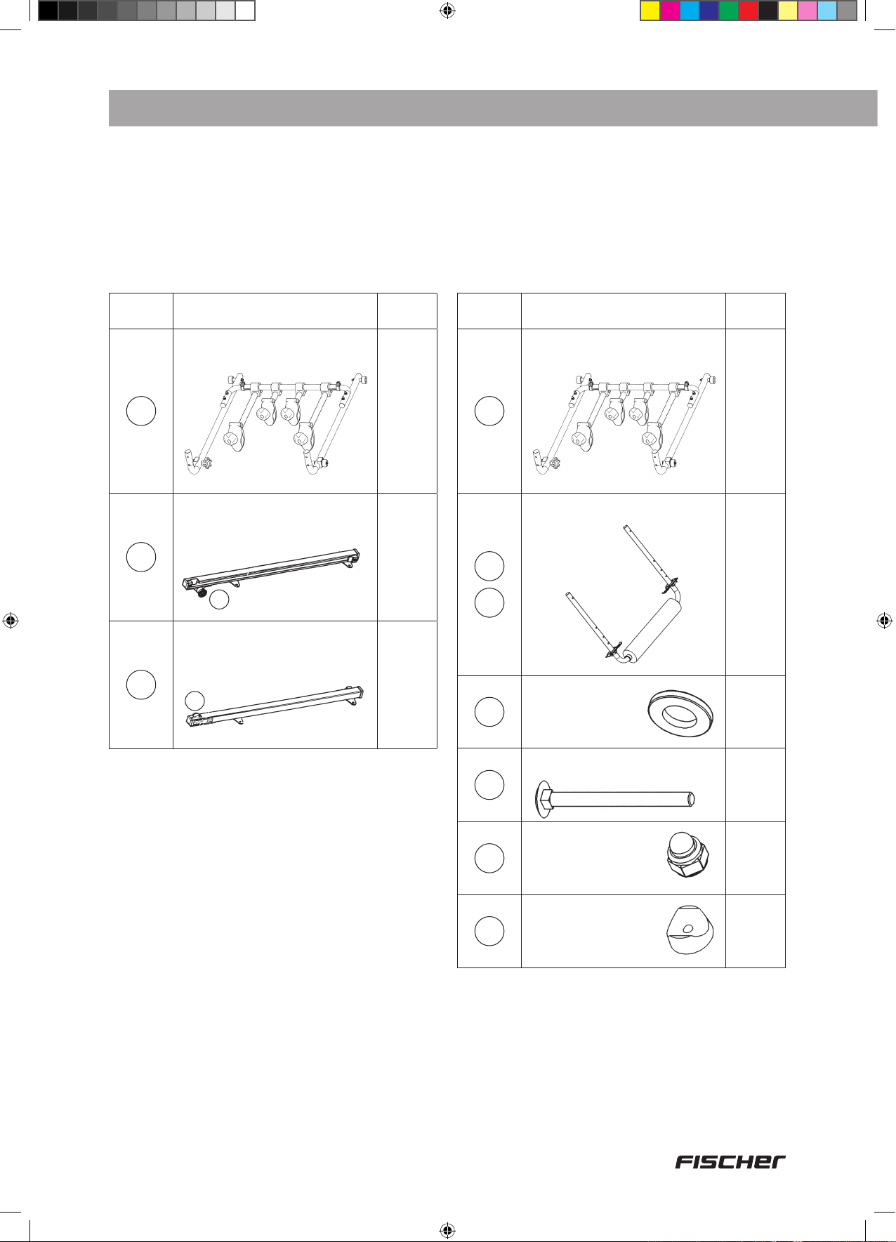
Nun sind Basiseinheit und Führungsschienen voneinander getrennt.
Vor Ihnen liegen die Teile:
Teile Nr. Abbildung Anzahl
Basiseinheit (1)
1
Führungsschiene links (3)
(Stützrolle (3a) liegt rechts)
3
3a
1
1
Schritt 4
Vormontage des Fahrrad-Tragebügels (2) an die Basiseinheit (1)
Für diesen Aufbauschritt benötigen Sie
folgende Bauteile:
Teile Nr. Abbildung Anzahl
Basiseinheit (1)
1
Fahrradtragebügel (2)
inkl. Schellen
2
2c
1
1
Führungsschiene rechts (4)
(Stützrolle (4a) liegt links)
4
4a
1
7
12
13
17
Unterlegscheibe,
6,5 mm, klein
Schlossschraube M6 x 70 mm
Hutmutter M6
Abstandhalter
4
4
4
2
9
18092_Betriebsanleitung_D_GB_F_IT_PL.indd 9 13.02.15 11:25
Page 10

1. Vor der Montage Schellen (2c) am Fahrrad-
Tragebügel lösen (nicht vollständig abdrehen). Zur Anpassung der Breite des FahrradTragebügels (2) an die Breite der Basiseinheit (1) die Rundrohre links und rechts aus
dem Überwurfrohr ziehen bzw. einschieben.
2. Schlossschraube (12) an der Innenseite der
Basiseinheit durch die Bohrungen stecken
3. An Außenseite Abstandhalter (17) und
Fahrrad-Tragebügel durch innere Bohrungen
aufstecken.
4. Auf der Gegenseite Unterlegscheibe (7)
aufstecken und Hutmutter (13) aufschrauben.
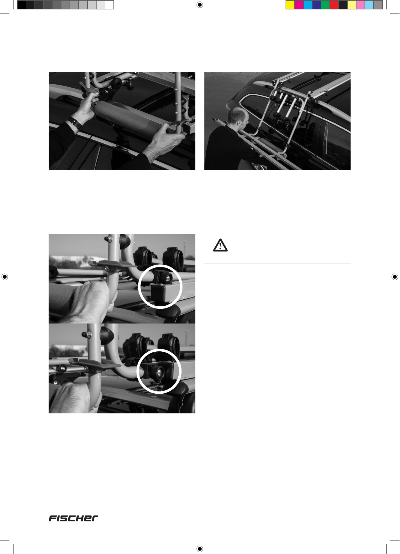
UNBEDINGT BEACHTEN!
Rechte Sicherungsklammer –
rechts Linke Sicherungsklammer
– links
(Ausschnitt rechte Sicherungsklammer)
1
R
13
13
12
2
12
7
17
7
2c
13
13
7
7
2c
17
10
18092_Betriebsanleitung_D_GB_F_IT_PL.indd 10 13.02.15 11:25
Page 11
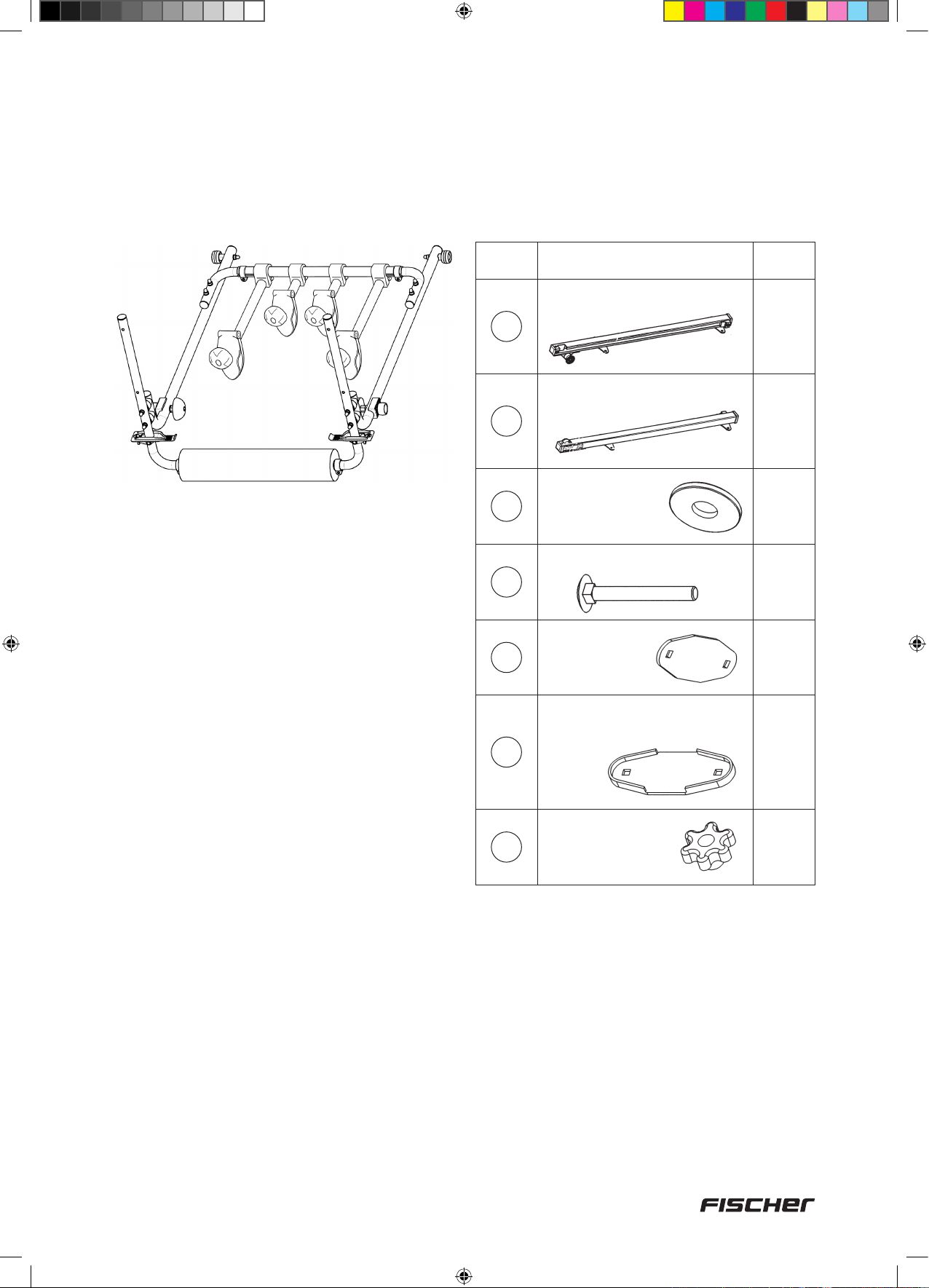
Schritt 5
Schritt 6
Vor Ihnen liegt die Trageeinheit
Montage der Führungsschienen (3+4)
auf den Grundträger
Für diesen Aufbauschritt benötigen Sie
folgende Bauteile:
Teile Nr. Abbildung Anzahl
Führungsschiene links
3
Führungsschiene rechts
4
Unterlegscheibe,
8
6,5 mm, groß
1
1
8
Schlossschraube M6 × 50 mm
11
14
15
16
Befestigungsplatte
Schutzprol für
Befestigungplatte und Grund-
platte
Rändelmutter M6
8
4
8
8
Beide Tragebarren des Grundträgers sind aus-
gerichtet, d. h. parallel in gleichen Abstand.
Empfehlens wert ist, dass der Dachlift auf der
Beifahrerseite abgesenkt wird (SICHERHEIT
IM STRASSEN VERKEHR).Deshalb erfolgt
die Montage der Führungsschienen von der
Beifahrerseite aus.
11
18092_Betriebsanleitung_D_GB_F_IT_PL.indd 11 13.02.15 11:25
Page 12

1. Schutzprofile (15) auf Grundplatte der
Führungs schiene (3b+c/4b+c) und
Befestigungsplatte (14) aufdrücken.
3. Schlossschraube (11) – bei Grundträgern mit
Barrenhöhe größer als 35 mm Schlossschrauben (12) verwenden – von oben in
Bohrung der Grund platten (3b+c/4b+c)
stecken, von unten Befes ti gungs platte (14)
mit Gummi profil nach oben und Unterlegscheibe (8) aufstecken. Rändelmutter (16)
aufschrauben. Vordere Be festi gungs platten
fest aufschrauben. Hintere Befesti gungs-
platten nur locker anschrauben.
15
15
14
2. Führungsschiene (3+4) mit der Öffnung nach
vorne auf den Tragebarren auflegen.
Bei Grundträgern mit Barrenhöhe größer als 35 mm
11
Schloss
schrauben (12)
verwenden
8
Grundträger
16
HINWEIS:
Die hinteren Befesti gungsplatten
werden nur locker an geschraubt,
damit sich die Füh rungsschienen
beim Ein schie ben der Trageeinheit
ausrichten können.
12
WICHTIG!
Die Stützrolle (3a+4a) muss mindestens auf Höhe der Dachkante (nicht
weiter innen) liegen.
TIP:
Zur Erleichterung der Be festigung
der Führungs schienen auf dem
Grundträger die Befestigungsplat-
ten an einer Seite vormontieren.
18092_Betriebsanleitung_D_GB_F_IT_PL.indd 12 13.02.15 11:25
Page 13

Schritt 7
Breitenanpassung der Trageeinheit an Breite der Führungsschienen.
Die Führungsschienen sind auf den
Grundträger montiert.
1. Schellenschrauben (1e+2c) an Trageeinheit
lösen (nicht vollständig abschrauben).
Die eingesteckten Rundrohre lassen sich
verschieben.
ACHTUNG!
Mindest-Einstecktiefe beträgt
65 mm. Bei Erreichen der
maximalen Breite erscheint eine
Markierung.
1e
1e
3. Trageeinheit vorsichtig mit SchaumstoffProfil (2b) an die Fahrzeugseite anlehnen
und überprüfen, dass das Überwurf-Rohr
mittig
oniert
zwischen linker und rechter Seite positi-
ist, gegebenenfalls mittig verschieben.
Nochmals prüfen, dass die maximale Breite
nicht überschritten ist (Markierung beachten).
4. Schellenschrauben (1e) an Trageeinheit
festdrehen.
Überwurfrohr
2c
2. Hintere Führungsrolle (1d) der Trageeinheit
auf einer Seite in die Öffnung der Führungs-
schiene einhängen, andere Seite so lange
verschieben bis die Führungs rolle (1d) in
die Öffnung der Führungsschiene passt und
ebenfalls einhängen.
5. Trageeinheit, wie in Schritt 10. beschrieben,
hochliften und Breite des Fahrrad-Tragebügels so einstellen, dass die vorderen
Führungsrollen (1c) in die Öffnungen der
Führungs schienen passen. Danach
Schellenschrauben (2c) festdrehen und
Trage ein heit, wie in Schritt 11. be schrie ben
wieder an die Fahrzeugseite absenken.
13
18092_Betriebsanleitung_D_GB_F_IT_PL.indd 13 13.02.15 11:25
Page 14

Schritt 8
Zusammenstecken der Profilschienen (5)
Für diesen Aufbauschritt benötigen Sie
folgende Bauteile:
Teile Nr. Abbildung Anzahl
Fahrrad-Prolschiene 750 mm
13
5
Schutzkappe für Fahr-
6
8
9
rad-Prolschiene
Unterlegscheibe,
6,5 mm, groß
Schraube
M6 × 16 mm
Hutmutter M6
4
8
8
8
8
1. Jeweils 2 Profilschienen (5) in der Mitte
zusammen legen.
2. Schraube (9) zuerst durch Unterleg scheibe
(8), dann an der Innenseite der Profil schiene
durch die Lochung stecken.
3. An Außenseite Unterleg scheibe (8) aufsetzen
und Hutmutter (13) aufschrauben.
4. Schutzkappen (6) auf beide Enden stecken.
5
9
8
5
8
13
6
14
18092_Betriebsanleitung_D_GB_F_IT_PL.indd 14 13.02.15 11:25
Page 15

Schritt 9
Montage der Profilschiene (5) auf Trageeinheit
Für diesen Aufbauschritt benötigen Sie
folgende Bauteile:
Teile Nr. Abbildung Anzahl
Fahrrad-Prolschiene 750 mm
5
Unterlegscheibe,
7
6,5 mm, klein
2
4
8
10
13
Unterlegscheibe,
6,5 mm, groß
Schraube M6 × 35 mm
Hutmutter M6
4
4
4
Die Trageeinheit ist in der Breite angepaßt und
in die Führungs schienen (3+4) eingehängt.
Jetzige Position:
Trageeinheit an Fahrzeugseite angelehnt.
1. Profilschiene (5) an Oberseite des FahrradTragebügels anhalten.
2. Schraube (10) zuerst durch Unterlegscheibe
(8), dann von oben nach unten durch
Bohrung des Fahrrad-Tragebügels stecken.
3. Auf Unterseite Unterlegscheibe (7) auf setzen
und Hutmutter (13) aufschrauben.
10
5
510
8
8
7
13
13
7
HINWEIS:
Beachten Sie, dass der Überstand
der Prolschiene links und rechts
gleich ist.
15
18092_Betriebsanleitung_D_GB_F_IT_PL.indd 15 13.02.15 11:25
Page 16

Schritt 10
Hochliften der Trageeinheit auf das Fahrzeugdach
Für diesen Aufbauschritt benötigen Sie
folgende Bauteile:
Teile Nr. Abbildung Anzahl
Inbus-Schlüssel, 5 mm
23
1
Die Profilschienen sind montiert. Die komplette
Trageeinheit kann nun auf das Fahrzeugdach
geliftet werden.
3. Trageeinheit vorne leicht anheben und
vordere Führungsrollen in Öffnung der
Führungs schienen absenken.
1. Trageeinheit links und rechts neben
Schaumstoffprofil (2b) greifen und nach
oben ziehen.
2. Bei Erreichen der waagrechten Position
Trageeinheit nach hinten drücken, bis
vordere Führungsrollen (1c) an die
Führungsschienen (3+4) anschlagen.
4. Trageeinheit weiter nach hinten drücken,
bis Sicherungsklammern (2a) selbständig in
Öffnung der Führungsschienen einrasten.
Handrad (1f) links und rechts festdrehen.
5. Nachdem die Trageeinheit in die Schienen
eingeschoben wurde muss der Anschlag-
punkt auf der Gegenseite exakt eingestellt
werden.
16
18092_Betriebsanleitung_D_GB_F_IT_PL.indd 16 13.02.15 11:25
Page 17

Inbusschrauben (5 mm) an den Anschlagpuffern lösen (nicht vollständig abschrauben).
Die An schlagpuffer können nun verschoben
werden.
Richtige Einstellung:
Rundrohr der
Trageeinheit
Nur nach Erstmontage:
Inbusschlüssel
5 mm
23
Anschlagpuffer
Die Rundrohre der Trage einheit müssen bündig an den Anschlag puffern anschlagen. Nach
korrekter Einstellung Inbus schraube wieder
festdrehen.
HINWEIS:
1. Falls keine Fahrräder geladen
sind, vor dem Hochliften der Tra-
geeinheit beide Fahrrad-Haltearme
(1a+1b) senkrecht stellen und
Handräder festdrehen. So können
die Haltearme das Fahrzeugdach
und die Seitenscheiben nicht berühren.
2. Falls Fahrräder geladen sind,
vor dem Hochliften der Trageeinheit
beide Fahrräder mit den FahrradSicherungsgurten (18) an den Fahrradfelgen sichern!
6. In Schritt 6.3 wurden die hinteren
Befestigungsplatten (14) nur locker angeschraubt (für Ausrichtung der Führungsschienen). Jetzt können die hinteren
Befestigungsplatten festgeschraubt werden.
17
18092_Betriebsanleitung_D_GB_F_IT_PL.indd 17 13.02.15 11:25
Page 18
Schritt 11
Absenken der Trageeinheit vom Fahrzeugdach an die Fahrzeugseite
1. Handrad (1f) links und rechts lösen (nicht
vollständig abdrehen!). Trageeinheit links und
rechts neben Schaumstoff-Profil (2b) greifen
und Sicherungsklammern (2a) mit dem
Daumen nach unten drücken.
3. Trageeinheit weiter nach vorne ziehen, bis
hintere Führungsrollen (1d) in der Führungsschiene anschlagen und langsam absenken,
bis Schaumstoff-Profil (2b) an Fahrzeugseite
anliegt.
HINWEIS:
Schaumstoff-Prol vor jedem
Anlegen auf Sauberkeit prüfen.
2. Trageeinheit nach vorne ziehen, bis vordere
Führungs rollen (1c) in der Führungs schiene
anschlagen. Vordere Führungsrollen (1c)
durch leichtes Anheben der Trageeinheit aus
den Öffnungen der Führungsschiene heben,
weiter nach vorne ziehen und vor den
Führungs schienen ablegen.
18
18092_Betriebsanleitung_D_GB_F_IT_PL.indd 18 13.02.15 11:25
Page 19

Schritt 12
Beladen der Fahrräder
1. Beim Beladen von 2 Rädern: Vor dem
Be laden des inneren Fahr rades den Lenker
drehen. Beladung mit Lenker nach rechts,
Lenker des Fahr rades nach rechts drehen.
Beladung mit Lenker nach links, Lenker des
Fahr rades nach links drehen. Der Fahrradlenker darf das Fahrzeugdach nicht berüh-
ren!
ACHTUNG!
Beim Beladen von 2 Fahrrädern:
Die langen Haltearme zwischen
dem Rahmen des ersten Fahrrades
waagerecht stellen! Pedalstellung
des ersten Fahrrades beachten
(Pedale zwischen Rahmen des
2. Fahrrades).
2. Trageeinheit, wie in Schritt 11. beschrieben,
an die Fahrzeugseite absenken, Handrad
am Fahrzeughaltearm lösen (nicht vollständig abschrauben!) und Fahrrad in die
Profilschiene (5) stellen. Die Rahmenklammer
am Fahrrad-Haltearm (1a+1b) muss um
das Rahmenrohr des Fahrrades greifen. Die
Flucht des Fahrrad-Halte armes soll gerade
zur Trageeinheit verlaufen.
3. Je zwei Fahrrad-Sicherungsgurte (18) um
Radfelge und Profilschiene legen und festzurren. Die Gurte müssen möglichst außen
angebracht werden.
4. Beide Fahrräder mit Sicherungsgurt (21)
sichern.
5. Dachlift wie in Schritt 10. hochliften und
Sicherungsschrauben (1f) festziehen.
3. Beachten Sie, dass sich die Fahrräder nicht gegenseitig berühren! Gegebenenfalls
4. Aufbauten am Fahrrad (z. B. Kindersitz) vor dem Beladen demontieren.
WICHTIGE HINWEISE!
1. Wird nur ein Fahrrad transportiert, die äußere Prolschiene benutzen.
2. Bei niedrigen Grundträgern muss gegebenenfalls auch bei dem äußeren Fahrrad
der Lenker leicht gedreht werden.
müssen entsprechende Einstellungen (z.B. Sattel) vorgenommen werden.
19
18092_Betriebsanleitung_D_GB_F_IT_PL.indd 19 13.02.15 11:25
Page 20

Schritt 13
Abnehmen und Aufbewahren der beladenen Trageeinheit
Für diesen Aufbauschritt benötigen Sie
folgende Bauteile:
Teile Nr. Abbildung Anzahl
19
20a
20b
20c
Haken
2
4
4
4
Mit beiliegenden Schraubhaken 6 mm und
Dübeln 6 mm kann die beladene Trageeinheit
an geeigneter Stelle (Keller- oder Garagenwand) platz sparend aufgehängt werden.
Die Trageeinheit wie in Schritt 11. beschrieben an die Fahrzeugseite absenken und
mit Hilfsperson aus Öffnungen in den
Führungsschienen heben.
7. Service, Hersteller
21
PAP
INTER-UNION Technohandel GmbH
Klaus-von-Klitzing-Straße 2 · 76829 Landau · Germany · Tel. (0 63 41) 2 84-0 · www.inter-union.de
20
18092_Betriebsanleitung_D_GB_F_IT_PL.indd 20 13.02.15 11:25
Page 21

DE
Fahrradträger »Dachlift« ........................................................
– für den sicheren liegenden Transport von zwei Fahrrädern –
GB
Bicycle rack »Roof lift« .........................................................
– for safe transport of two bicycles in horizontal position –
Original instructions Art. no.: 18092 Version 02/2015
21
Table of contents
1. Safety instructions ....................................................................................... 22
2. Intended use ................................................................................................. 23
3. Assembly tools ............................................................................................. 23
4. Parts list for roof lift bike rack .................................................................... 24
5. General preliminary information ................................................................ 27
6. Assembly ....................................................................................................... 29
7. Service, manufacturer ................................................................................. 40
F
Porte-vélos avec aide au »levage sur le toit« .....................
– pour le transport sûr et couché de deux bicyclettes –
41
2
IT
Portabici »Tetto auto« ........................................................... 61
– per il trasporto sicuro di 2 biciclette in posizione orizzontale –
PL
Bagażnik na rowery »Dachowego bagażnika« ...................
– do bezpiecznego przewożenia maks. dwóch rowerów (w pozycji leżącej) –
18092_Betriebsanleitung_D_GB_F_IT_PL.indd 21 13.02.15 11:25
81
Page 22

Dear customer,
Thank you for choosing the FISCHER Roof Lift Bike Rack. With this roof lift bike rack,
you can easily and safely transport two horizontally positioned bicycles with your vehicle.
The roof lift bike rack is delivered as an assembly set.
Before use, you must first assemble the roof lift bike rack carefully, following these
operating instructions.
1. Safety instructions
NOTE: Read these operating instructions carefully before beginning assembling the roof lift bike
rack! Observe all safety instructions!
• Keep the operating instructions for the duration of the product‘s service life
• Include the operating instructions if you give the product to any other person, either for use or
to own
IMPORTANT: Please review the max. permissible roof bearing capacity as indicated by your
vehicle manufacturer. This bike rack was developed, manufactured and tested with the utmost
care and in compliance with all applicable safety standards.
• Check screw connections regularly before departure.
• After having driven 10 km and then at regular intervals, check to make sure the rack and
bicycles are still rmly fastened.
• Drive with a style and speed appropriate for transport. A vehicle‘s dynamic handling changes
greatly when the roof rack is loaded. We therefore strongly recommend not exceeding the
max. speed limit of 130 kph. We accept no liability for damages incurred in extreme situations
due to excessive speed.
• Avoid empty running! Disassemble the bike rack when it is not in use.
• As the driver, the law requires you to secure all loads appropriately.
• Bike rack dead weight: 13.8 kg; max. load: two bikes (15 kg each).
• Make sure that the base support has the appropriate bearing capacity.
Bearing capacity = Bike rack + bikes
• You must observe the manufacturer‘s information about the max. permissible roof load.
Roof load = base support + bike rack + bikes.
• Please bear in mind that the increased total height of your vehicle, especially in low clearance
heights (garages, underground garages, bridges). Assembly height of base support
approx. 60 cm.
• The rack and bikes may not project from the sides of the vehicle.
• For your own safety when loading and unloading bikes, we recommend assembling the rack to
lower on the passenger‘s side.
• Store the replacement key for the lockable hand wheel at a separate location.
• Keep the assembly instructions.
• The distributor and manufacturer accept no liability for any vehicle and/or bicycle damaging
resulting from failure to observe the assembly instructions and safety instructions.
Warning
22
18092_Betriebsanleitung_D_GB_F_IT_PL.indd 22 13.02.15 11:25
Page 23

2. Intended use
The roof lift bike rack is used to transport two bicycles on a vehicle roof. The roof lift bike rack
must be assembled according to these operating instructions. Observe all applicable regulations
(max. speed limit, max. permissible total weight, etc.) when driving.
3. Tools required for assembly
The following tools are required for assembly:
2 x Ø 10 mm
23
18092_Betriebsanleitung_D_GB_F_IT_PL.indd 23 13.02.15 11:25
Page 24

4. Parts list for roof lift bike rack
Caution: Make sure no children are in the vicinity when working with these individual
parts. The bike rack contains small parts that pose a choking hazard!
Base unit
Parts No. Image Label Function / Use Quantity
1
1a
1b
1d
1a
+ bike carrying bracket
1
1e
1e
1d
1b
Base unit
Bike bracket arm,
290 mm, 1x lockable
Bike bracket arm,
100 mm
= carrying unit
2
Fastening outer wheel
(preassembled on base
unit)
Fastening inner wheel
(preassembled on base
unit)
1
2
2
1c
1d
1e
1f
Parts No. Image Label Function / Use Quantity
1c
1f
1f
1c
2
2a
2a
2c
2b
2a
2c
2b
Front guide roller
Back guide roller
Clamps Width adjustment
Hand wheel
Bike carrying
bracket
Safety clamp
Foam prole
Base unit guide in guide
rails (preassembled)
Base unit safety lock in
guide rails (preassembled
on base unit)
Bike uptake (assembly
on base unit)
Additional safety lock
for carrying unit (preassembled on base unit)
with „L“ and „R“ markings
Padding on driver‘s side
(preassembled to bike
carrying bracket)
2
2
2
2
1
2
1
2c
Clamps Width adjustment
2
24
18092_Betriebsanleitung_D_GB_F_IT_PL.indd 24 13.02.15 11:25
Page 25

Parts No. Image Label Function / Use Quantity
3
3a
3b
3c
Parts No. Image Label Function / Use Quantity
4
4a
The support roller (3a) is on
the right
3b
3a
The support roller (4a) is on
the right
4a
4b
3c
4c
Left guide rail
Support roller
Front base plate Rest on base support
Back base plate
Right guide rail
Support roller
Base unit guide /
Assembly on base support
Guide for extended
carrying unit (preassembled on guide rail)
(preassembled on guide
rails)
Base unit guide /
Assembly on base support
Guide for extended
carrying unit (preassembled on guide rail)
1
2
1
1
1
2
4b
4c
Parts No. Image Label Function / Use Quantity
5
6
7
8
Front base plate
Back base plate
Bike prole guide
750 mm
Protective cap for
bike prole guide
Washer,
6.5 mm, small
Washer,
6.5 mm, large
Rest on base support
(preassembled on guide
rails)
Bike uptake (assembly on
bike carrying bracket)
Prole guide edge
protection (assembly on
bike prole guide)
For assembly of bike prole
guide on carrying unit (4x)
For assembly of bike
carrying bracket on base
unit (4x)
Connection for bike prole
guides (8x), For assembly
of bike prole guides on
carrying unit (4x), For
assembly of guide rails
on base support (8x)
1
1
4
4
8
20
9
10
Screw M6 x 16 mm
Screw M6 x 35 mm
Connection for bike
prole guides
For assembly of bike prole
guides on carrying unit
4
4
25
18092_Betriebsanleitung_D_GB_F_IT_PL.indd 25 13.02.15 11:25
Page 26
Parts No. Image Label Function / Use Quantity
11
12
13
14
15
16
Carriage bolt
M6 x 50 mm
Carriage bolt
M6 x 70 mm
Cap nut M6
Mounting plate
Protective prole for
mounting plate and base
plate
Lock nut M6
For assembly of guide rail
on base support with bar
height up to 35 mm
For assembly of bike carrying
bracket on base unit (4x)
For assembly of guide rail on
base support with bar height
great than 35 mm (8x)
Screw connections
(except on guide rail)
Assembly on the bottom of
base support
Assembly to mounting plate
For mounting guide rail to
base support
8
12
12
4
8
8
17
18
19
20a
20b
20c
21
Spacer
Bike safety belt,
330 mm
Hook
Wall anchor, 6 mm
Screw M6 x 45 mm
Washer 6.5 mm
Bike safety belt, 5 m
For assembly between bike
carrying bracket and base unit
For securing bikes to prole
guides, for assembly on bike
rims and prole guide
For suspension of
carrying unit
Hook fastening (19)
connection for bike
prole guides
For securing bikes to prole
guides.
8
8
2
4
4
4
1
22
23
Open-end wrench,
10/13 mm
Hex key, 5 mm For setting bump stops
For all screw connections on
bike rack (wrench size 10 mm)
1
1
26
18092_Betriebsanleitung_D_GB_F_IT_PL.indd 26 13.02.15 11:25
Page 27
The carrying unit can be moved forward and
backward in the guide rails (3+4).
3
1
base support
4
5. General preliminary information
Step 1
base support – Prerequisite for proper functioning of the roof lift bike rack
2
The base support must first be mounted to the
vehicle roof.
Please observe the following!
Both carrying bars must be mounted parallel
to one another and at the same distance.
With many vehicles, the mounting position
is predetermined by the manufacturer and
indicated by markings.
Vehicles with a rain gutter or roof rails do not
have any set mounting position predetermined
by the manufacturer. In this case, the bar
distance should be at least 70 cm and not
exceed 87 cm.
Note: Use a tape measure to check the
distance between bars.
Distance at least 70 cm, max. 87 cm
IMPORTANT! Mount carrying bars
parallel to one another and at the
same distance.
70 – 87 cm
27
18092_Betriebsanleitung_D_GB_F_IT_PL.indd 27 13.02.15 11:25
Page 28

Step 2
Preparing the rack for assembly, remove the base unit (1) from the guide
rails (3+4)
On delivery, the base unit (1) is inserted
into the guide rollers to protect the guide
rollers (1c+1d). Before being mounted to the
vehicle, the base unit and guide rails must be
separated.
1. Loosen the hand wheel (1f) left and right (do
not screw off completely!)
2. Push the guide rails (3+4) back until the front
guide roller (1c) hits the opening in the rail
and projects from the opening.
3. Push the guide rails (3+4) further back until
the back guide roller (1d) hits the opening
in the rail and base unit projects from the
opening.
1
3
1f
4
push
2
3
28
18092_Betriebsanleitung_D_GB_F_IT_PL.indd 28 13.02.15 11:25
Page 29
6. Assembly
Step 3
Now the base unit and guide rails are
separated.
Parts in front of you:
Parts No. Image Quantity
Base unit (1)
1
Left guide rail (3)
(Support roller (3a) is on the
3
right)
3a
1
1
Step 4
Preassembling the bike carrying
bracket (2) on the base unit (1)
The following parts are required for this
assembly step:
Parts No. Image Quantity
Base unit (1)
1
Bike carrying bracket (2)
incl. clamps
2
2c
1
1
Right guide rail (4)
(Support roller (4a) is on the
4
left)
4a
1
7
12
13
17
Washer,
6.5 mm, small
Carriage bolt M6 x 70 mm
Cap nut M6
Spacer
4
4
4
2
29
18092_Betriebsanleitung_D_GB_F_IT_PL.indd 29 13.02.15 11:25
Page 30
1. Before assembly, loosen the clamps (2c) on
the bike carrying bracket (do not screw off
completely). To adjust the width of the bike
carrying bracket (2) to the width of the base
unit (1) pull out/push in the round tubes on
the left and right of the retaining tube.
2. Insert the carriage bolt (12) on the bottom
of the base unit through the holes.
3. On the outside, attach the spacer (17)
and bike carrying bracket through the
inner holes.
FOLLOW THIS STEP!
Right safety clamp - right Left safety clamp - left
R
4. On the other side, attach the washer (7)
and screw on the cap nut (13).
12
2
7
(Notch right safety clamp)
1
12
7
30
13
13
17
7
2c
13
13
7
2c
17
18092_Betriebsanleitung_D_GB_F_IT_PL.indd 30 13.02.15 11:25
Page 31

Step 5
Step 6
The carrying unit is in front of you
Assembling the guide rails (3+4)
to the base support
The following parts are required for this
assembly step:
Parts No. Image Quantity
Left guide rail
3
Right guide rail
4
Washer,
8
6.5 mm, large
1
1
8
Carriage bolt, M6 x 50 mm
11
14
15
16
Mounting
plate
Protective prole for mounting
plate and base plate
Lock nut M6
8
4
8
8
Both carrying bars on the base support are
adjusted, parallel and at the same distance.
It is recommended to lower the roof lift on the
passenger‘s side (SAFETY IN TRAFFIC).
So assemble the guide rails from the
passenger‘s side.
31
18092_Betriebsanleitung_D_GB_F_IT_PL.indd 31 13.02.15 11:25
Page 32

1. Push the protective profile (15) onto the base
plate of the guide rails (3b+c/4b+c)
and mounting plate (14).
3. Insert carriage bolt (11) - for use with base
supports with a bar height greater than 35
mm, use carriage bolt (12) - from above into
the hole on the base plates (3b+c/4b+c),
attach mounting plate (14) from below with
the rubber profile facing upward and washer
(8). Screw on lock nut (16). Screw the front
mounting plate on securely. Screw the back
mounting plates on loosely.
15
15
14
2. Place the guide rail (3+4) on the carrying
bars with the opening facing forward.
For use with base supports
11
with a bar height greater than
35 mm use carriage bolt (12)
8
base support
16
NOTE:
The back mounting plates should
be screwed on loosely so that
the guide rails can align when the
carrying unit is pushed in.
IMPORTANT!
The support roller (3a+4a) must be
at least at a level with the roof edge
(not further inward).
TIP:
To ease mounting the guide rails
on the base support, premount the
mounting plate on one side.
32
18092_Betriebsanleitung_D_GB_F_IT_PL.indd 32 13.02.15 11:25
Page 33

Step 7
Adjusting the width of the carrying unit to the width of the guide rails.
The guide rails are mounted to the base
support.
1. Loosen clamp screws (1e+2c) on the
carrying unit (do not screw off completely).
The inserted round tubes can be moved.
CAUTION!
The minimum inserted length is
65 mm. A marking is visible when
the maximum width is reached.
1e
1e
3. Carefully lean the carrying unit with foam
profile (2b) on the side of the vehicle and
verify that the retaining tube is directly in
the middle of the left and right side – move
to the middle if necessary. Again verify that
the maximum width is not exceeded (heed
marking).
4. Fasten clamp screws (1e) on the carrying
unit.
Retaining tube
2c
2. Insert in the back guide roller (1d) on the
carrying unit on one side into the opening on
the guide rail move the other side until the
guide roller (1d) fits into the opening on the
guide rail and insert.
5. As described in Step 10, lift the carrying
unit and set the width of the bike carrying
bracket so that the front guide rollers (1c)
fit into the openings on the guide rails.
Then fasten clamp crews (2c) and lower the
carrying unit, as described in Step 11, back
onto the side of the vehicle.
33
18092_Betriebsanleitung_D_GB_F_IT_PL.indd 33 13.02.15 11:25
Page 34

Step 8
Connecting the profile guides (5)
The following parts are required for this
assembly step:
Parts No. Image Quantity
Bike prole guide 750 mm
5
6
8
9
13
Protective cap for bike
prole guide
Washer,
6.5 mm, large
Screw
M6 × 16 mm
Cap nut M6
4
8
8
8
8
1. Place 2 profile guides (5) together in the
middle.
2. Insert screw (9) first through the washer (8)
then through the hole on the inside of the
profile guide.
3. Attach washer (8) to the outside and screw
on cap nut (13).
4. Place protective caps (6) on both ends.
5
9
8
5
8
13
6
34
18092_Betriebsanleitung_D_GB_F_IT_PL.indd 34 13.02.15 11:25
Page 35

Step 9
Assembling the profile guides (5) on the carrying unit
The following parts are required for this
assembly step:
Parts No. Image Quantity
Bike prole guide 750 mm
5
Washer,
7
6.5 mm, small
2
4
8
10
13
Washer,
6.5 mm, large
Screw M6 × 35 mm
Cap nut M6
4
4
4
The width of the carrying unit is adjusted
properly and the carrying unit is inserted
through the guide rails (3+4).
Current position:
Carrying unit leaning on side of vehicle.
1. Hold the profile guide (5) to the top of the
bike carrying bracket.
10
5
510
8
8
2. Insert screw (10) first through the washer
(8), then from above through the hole on the
bike carrying bracket.
13
13
7
7
3. Attach the washer (7) to the bottom and
screw on cap nut (13).
NOTE:
Please note that the overhang of
the prole guide is the same on the
left and right.
35
18092_Betriebsanleitung_D_GB_F_IT_PL.indd 35 13.02.15 11:25
Page 36

Step 10
Lifting the carrying unit onto the vehicle roof
The following parts are required for this
assembly step.
Parts No. Image Quantity
Hex key, 5 mm
23
1
The profile guides are mounted. The entire
carrying unit can now be lifted onto the roof of
the vehicle.
3. Slightly lift the carrying unit at the front and
lower the front guide rollers into the opening
on the guide rails.
1. Hold the carrying unit on the left and right
near the foam profile (2b) and lift upward.
2. When you reach the horizontal position,
push the carrying unit back until the front
guide rollers (1c) hit the guide rails (3+4).
4. Push the carrying unit further back until the
safety clamps (2a) click into the opening on
the guide rails themselves. Tighten the hand
wheel (1f) left and right.
5. After the carrying unit is inserted into the
rails, you need to set the attachment point
on the opposite side exactly.
36
18092_Betriebsanleitung_D_GB_F_IT_PL.indd 36 13.02.15 11:25
Page 37

Loosen the hex screws (5 mm) on the bump
stops (do not screw off completely).
The bump stops can now be adjusted.
Correct setting:
Round tube on
carrying unit
Only after first assembly:
Hex key,
5 mm
23
Bump stop
The round tubes on the carrying unit should
be flush with the guide rails. After making the
correct setting, tighten the hex screw.
NOTE:
1. If no bikes are loaded, set both
bike bracket arms (1a+1b) vertically
before lifting the carrying unit and
tighten the hand wheels. In this
way, the bracket arms cannot touch
the vehicle roof and side windows.
2. If bikes are loaded, secure both
bikes using the bike safety belts
(18) on the bikes‘ rims before lifting
the carrying unit!
6. In Step 6.3, the back mounting plates (14)
were screwed on loosely (to adjust the guide
rails). The back mounting plates can now be
tightened.
37
18092_Betriebsanleitung_D_GB_F_IT_PL.indd 37 13.02.15 11:25
Page 38

Step 11
Lower the carrying unit from the vehicle roof onto the vehicle side
1. Loosen the hand wheel (1f) left and right (do
not screw off completely!). Hold the carrying
unit on the left and right near the foam
profile (2b) and push the safety clamps (2a)
down with your thumb.
3. Pull the carrying unit further forward until
the front guide rollers (1d) stop in the guide
rail and lower slowly until the foam profile
(2b) is resting on the side of the vehicle.
NOTE:
Check the foam prole before
resting to make sure it is clean.
2. Pull the carrying unit forward until the front
guide rollers (1c) stop in the guide rails.
Remove the front guide rollers (1c) from
the openings in the guide rail by lifting the
carrying unit slightly, pull forward and place
in front of the guide rails.
38
18092_Betriebsanleitung_D_GB_F_IT_PL.indd 38 13.02.15 11:25
Page 39

Step 12
Loading bikes
1. When loading 2 bikes: Before loading the
inner bike, turn the handlebars. To load
with the handlebars on the right, turn the
bike handlebars to the right. To load with
the handlebars on the left, turn the bike
handlebars to the left. The bike handlebars
may not touch the vehicle roof!
CAUTION!
When loading 2 bikes: Place the
long bracket arms horizontally
between the frame of the rst bike!
Check the position of the pedals of
the rst bike (pedals between the
frame of the second bike).
2. As described in Step 10, lower the carrying
unit onto the side of the vehicle, loosen the
hand wheel on the vehicle bracket arm
(do not loosen completely!) and place bike in
the profile guide (5). The frame clamp on the
bike bracket arm (1a+1b) should fit around
the bike‘s frame tube. The bike bracket arm
should be parallel with the carrying unit.
3. Place two bike safety belts (18) over the bike
rim and profile guides and tie down firmly.
The safety belts shall face outwards.
4. Secure both bikes using safety belt (21).
5. As described in Step 10, lift roof lift and
fasten safety screws (1f).
2. When used with low base supports, you will also need to turn the handlebar of the
3. Make sure that the bikes do not touch! It may be necessary to make appropriate
4. Remove all structures mounted to the bike (such as children‘s seats) before
IMPORTANT NOTES!
1. If you are transporting just one bike, use the outer prole guide.
outer bike.
adjustments (e.g. seat).
loading.
39
18092_Betriebsanleitung_D_GB_F_IT_PL.indd 39 13.02.15 11:25
Page 40

Step 13
Remove and store the loaded carrying unit
The following parts are required for this
assembly step.
Parts No. Image Quatity
Hook
19
20a
20b
20c
2
4
4
4
Using the included screw hook 6 mm and
wall anchors 6 mm, the loaded carrying unit
can be suspended in a suitable location
(basement or garage wall) with minimum space
requirements.
As described in Step 11, lower the carrying unit
onto the side of the vehicle and, with the aid
of a second person, lift it from the openings in
the guide rails.
7. Service, manufacturer
21
PAP
INTER-UNION Technohandel GmbH
Klaus-von-Klitzing-Straße 2 · 76829 Landau · Germany
Phone (+49 63 41) 2 84-0 · www.inter-union.de
40
18092_Betriebsanleitung_D_GB_F_IT_PL.indd 40 13.02.15 11:25
Page 41

w
D
Fahrradträger »Dachlift« ........................................................
– für den sicheren liegenden Transport von zwei Fahrrädern –
GB
Bicycle rack »Roof lift« .........................................................
– for safe transport of two bicycles in horizontal position –
F
Porte-vélos avec aide au »levage sur le toit« .....................
– pour le transport sûr et couché de deux bicyclettes –
Mode d’emploi original Art. no° 18092 Version 02/2015
21
41
Table des matières
1. Consignes de sécurité ................................................................................. 42
2. Utilisation conforme aux prescriptions ..................................................... 43
3. Outil pour l‘assemblage .............................................................................. 43
4. Liste des pièces du porte-vélos avec levage sur le toit .......................... 44
5. Informations générales préalables ............................................................ 47
6. Assemblage .................................................................................................. 49
7. Service, fabricant ......................................................................................... 60
2
IT
Portabici »Tetto auto« ........................................................... 61
– per il trasporto sicuro di 2 biciclette in posizione orizzontale –
PL
Bagażnik na rowery »Dachowego bagażnika« ...................
– do bezpiecznego przewożenia maks. dwóch rowerów (w pozycji leżącej) –
18092_Betriebsanleitung_D_GB_F_IT_PL.indd 41 13.02.15 11:25
81
Page 42

Cher client, chère cliente,
Merci beaucoup d’avoir choisi un porte-vélos FISCHER avec un système de levage sur
le toit. Avec ce porte-vélos et son système de levage sur le toit, vous pouvez transporter
facilement et en toute sécurité deux bicyclettes couchés sur votre voiture. Ce porte-vélos
avec levage sur le toit est livré en kit de montage.
Avant la première utilisation, vous devez assembler soigneusement le porte-vélos avec
levage sur le toit en vous reportant à ce mode d’emploi.
1. Consignes de sécurité
REMARQUE : lisez toujours attentivement ce mode d’emploi avant de commencer avec le
montage du porte-vélos avec levage sur le toit ! Respectez particulièrement toutes les consignes
de sécurité !
• Conservez le mode d’emploi durant toute la durée de vie du produit !
• Transmettez toujours le mode d‘emploi aux futures propriétaires et utilisateurs du produit !
IMPORTANT : respectez les indications du fabricant de votre voiture concernant la charge
maximale admissible sur le toit. Ce porte-vélos a été développé, fabriqué et vérifié avec soin et
répond aux prescriptions de la norme de sécurité.
• Vériez régulièrement tous les boulonnages avant d’effectuer un trajet !
• Après 10 km de trajet ainsi qu’à intervalles réguliers, vériez toutes les xations du porte-vélos
et des bicyclettes.
• Adaptez votre conduite et la vitesse au transport. Puisque le comportement dynamique
durant la conduite d’un véhicule avec un porte-vélos chargé est fortement modié, nous vous
recommandons de ne pas dépasser la vitesse maximale de 130 km/h. Pour des dommages
qui apparaissent dans des situations extrêmes dues à une vitesse excessive, aucune
responsabilité ne peut être assumée.
• Éviter les parcours à vide ! Si aucune bicyclette n‘est transportée, démontez le porte-vélos.
• Le conducteur est responsable de son chargement et doit assurer une sécurité sufsante.
• Poids net du porte-vélos : 13,8 kg ; charge maximale avec deux bicyclettes (chacune de 15 kg).
• Respectez absolument la capacité de charge admissible des barres du porte-vélos.
Capacité de charge = porte-vélos + bicyclettes
• Les indications du constructeur automobile sur la charge admise sur le toit doivent absolument
être respectées. Charge sur le toit = barres du toit + porte-vélos+ bicyclettes.
• Pensez toujours à la hauteur totale du véhicule modiée par sa charge, particulièrement
lorsque vous passez à des endroits dont la hauteur est basse (garages, garages en sous-sol,
ponts). Hauteur de construction à partir des barres de toit d’env. 60 cm
• Le porte-vélos et les bicyclettes ne doivent pas dépasser le contour du véhicule.
• Pour votre sécurité lors du chargement et déchargement des bicyclettes, nous vous
recommandons de monter le porte-vélos an qu‘il puisse être basculé du côté passager.
• Les clés de réserve pour la molette verrouillable doivent être conservées dans un autre endroit.
• Conservez la notice de montage.
• Le distributeur autant que le fabricant décline toute responsabilité lors de l’apparition de
dommages sur le véhicule et/ou sur les bicyclettes qui pourraient résulter du non-respect des
instructions de montage et des consignes de sécurité.
Avertissement
42
18092_Betriebsanleitung_D_GB_F_IT_PL.indd 42 13.02.15 11:25
Page 43
2. Utilisation conforme aux prescriptions
Le porte-vélos avec système de levage sur le toit sert au transport de deux bicyclettes sur le toit
d‘une voiture. Le porte-vélos avec levage sur le toit doit être assemblé conformément à ce mode
d’emploi. Pendant la conduite du véhicule, toutes les règlementations régies par la loi (vitesse
maximale autorisée, poids total maximal admis, etc.) doivent être respectées.
3. Outil pour l‘assemblage
Pour le montage, vous aurez besoin de l’outil suivant :
2 x Ø 10 mm
43
18092_Betriebsanleitung_D_GB_F_IT_PL.indd 43 13.02.15 11:25
Page 44

4. Liste des pièces du porte-vélos avec levage sur le toit
Attention : lorsque vous travaillez avec toutes les pièces, veillez à ce qu‘aucun enfant
en bas âge ne se trouve à proximité. Le porte-vélos avec levage sur le toit contient
des petites pièces qui peuvent être avalées !
Élément de base
Pièce n° Illustration Désignation Fonction/utilisation Quantité
1
1a
1b
1c
1d
1d
1c
1e
1a
1f
+ étrier de transport pour bicyclette
1
élément de base
bras de support pour
bicyclette, 290 mm,
1 xation
1e
1b
1f
1c
bras de support pour
bicyclette, 100 mm
1d
Galet de guidage
avant
Galet de guidage
arrière
verrouillable de la roue
extérieure, (préassemblée
sur l’élément de base)
Fixation de la roue interne,
(préassemblée sur
l’élément de base)
Guidage de l’élément de
base dans les rails de
guidage (préassemblé)
= élément de transport
2
1
2
2
2
2
1e
1f
Pièce n° Illustration Désignation Fonction/utilisation Quantité
2
2a
2a
2c
2b
2a
2c
2b
Bride Réglage de la largeur
Sécurité de l’élément de
Molette
Étrier de transport
pour bicyclette
Clip de sécurité
Prolé avec
rembourrage en
mousse
base dans les rails de
guidage, préassemblé
sur l’élément de base
Insertion des bicyclettes
(montage sur l’élément
de base)
Sécurité supplémentaire
- élément de transport,
(préassemblé sur l’élément
de base) marqué avec
« L » ou « R »
Rembourrage du côté du
véhicule, (préassemblé
sur l’étrier de transport
pour bicyclette)
2
2
1
2
1
2c
Bride Réglage de la largeur
2
44
18092_Betriebsanleitung_D_GB_F_IT_PL.indd 44 13.02.15 11:25
Page 45

Pièce n° Illustration Désignation Fonction/utilisation Quantité
3
3a
3b
3c
Pièce n° Illustration Désignation Fonction/utilisation Quantité
4
4a
Roulette d‘appui (3a) se
trouvant à droite
3b
3a
Roulette d‘appui (4a) se
trouvant à droite
4a
4b
3c
4c
Rail de guidage
gauche
Roulette d‘appui
Socle avant Revêtement sur les barres
Socle arrière
Rail de guidage
droit
Roulette d‘appui
Guidage de l’élément de
transport/montage sur les
barres de toit
Guidage de l’élément
de transport enlevé
(préassemblé sur le rail
de guidage)
de toit (préassemblées sur
les rails de guidage)
Guidage de l’élément de
transport/montage sur les
barres de toit
Guidage de l’élément
de transport enlevé
(préassemblé sur le rail
de guidage)
1
2
1
1
1
2
4b
4c
Pièce n° Illustration Désignation Fonction/utilisation Quantité
5
6
7
8
Socle avant
Socle arrière
Rail prolé pour
bicyclette 750 mm
Clapet de protection
pour rail prolé pour
bicyclettes
Rondelle plate,
6,5 mm, petite
Rondelle plate,
6,5 mm, grande
Revêtement sur les barres
de toit (préassemblées sur
les rails de guidage)
Insertion des bicyclettes,
montage sur l’étrier de
transport de la bicyclette
Protection des arêtes pour
rail prolé, montage sur le
rail prolé pour bicyclettes
Montage du rail prolé pour
bicyclette sur l’élément de
transport (4x), Montage de
l’étrier de transport pour
bicyclette sur l’élément de
base (4x)
Raccordement des rails
prolés pour bicyclette (8x),
Montage des rails prolés
pour bicyclette sur l’élément
de transport (4x), Montage
des rails de guidage sur les
barres de toit (8x)
1
1
4
4
8
20
9
10
Vis M6 x 16 mm
Vis M6 x 35 mm
Raccordement des rails
prolés pour bicyclette
Montage des rails prolés
pour bicyclette sur
l’élément de transport
4
4
45
18092_Betriebsanleitung_D_GB_F_IT_PL.indd 45 13.02.15 11:25
Page 46

Pièce n° Illustration Désignation Fonction/utilisation Quantité
11
12
13
14
15
16
Vis à tête bombée
M6 x 50 mm
Vis à tête bombée
M6 x 70 mm
Écrou borgne M6
Plaque de xation
Prolé de protection
pour plaque de
xation et socle
Écrou moleté M6
Montage des rails de guidage sur
les barres de toit avec hauteur des
barres jusqu’à 35 mm
Montage de l’étrier de transport
pour bicyclette sur l’élément de
base (4x), Montage du rail de
guidage sur barres de galerie sur
hauteur des barres plus grande
que 35 mm (8×)
Raccordements boulonnés
(exception faite des rails de
guidage)
Montage en-dessous des barres
de toit
Montage sur la plaque
de xation
Fixation du rail de guidage sur
barres de toit
8
12
12
4
8
8
17
18
19
20a
20b
20c
21
Entretoise séparatrice
Sangle de sécurité
pour bicyclette,
330 mm
Crochet
Cheville, 6 mm
Vis M6 x 45 mm
Rondelle 6,5 mm
Sangle de sécurité
pour bicyclette, 5 m
Montage entre l’étrier de
transport pour bicyclette et
l’élément de base
Sécurité des bicyclettes sur les
rails prolés, Montage sur les
jantes des bicyclettes et sur le
rail prolé
Suspension de l’élément de
transport
Fixation du crochet (19)
Raccordement des rails prolés
pour bicyclette
Sécurité des bicyclettes sur les
rails prolés
8
8
2
4
4
4
1
Pour tous les raccordements
boulonnés sur le porte-vélos
(ouverture de la clé 10 mm)
Pour le réglage de l’amortisseur
d‘amplitude
1
1
22
23
Clé à fourche double,
10/13 mm
Clé hexagonale,
5 mm
46
18092_Betriebsanleitung_D_GB_F_IT_PL.indd 46 13.02.15 11:25
Page 47

L‘élément de transport peut être décalé vers l’avant
et vers l‘arrière dans les rails de guidage (3+4).
3
1
Barres de toit
4
5. Informations générales préalables
ère
1
étape
Les barres de toit – condition pour le fonctionnement parfait du porte-vélos
avec levage sur le toit
2
D‘abord, les barres de toit doivent être
installées sur le toit du véhicule.
À respecter absolument ! Les deux barres
de support doivent être installées parallèle
l’une à l’autre et montées à la même distance.
Sur de nombreux véhicules, les endroits de
montage sont indiqués par le constructeur
automobile grâce à des marquages.
Avec des véhicules p. ex. avec gouttière ou
barre de toit, aucun point fixe n‘est prévu par le
fabricant. Ici, la distance des barres doit avoir
au moins 70 cm et un maximum de 87 cm.
Remarque : utilisez un mètre afin de contrôler
la distance entre les barres !
Distance d’au moins 70 cm, maximum de
87 cm
IMPORTANT !
Les barres de support doivent être
montées parallèle avec le même
intervalle.
70 – 87 cm
47
18092_Betriebsanleitung_D_GB_F_IT_PL.indd 47 13.02.15 11:25
Page 48

2e étape
Préparation du porte-vélos pour le montage – Séparation de l‘élément de
base (1) des rails de guidage (3+4)
À la livraison, l’élément de base (1) est inséré
dans les rails de guidage afin de protéger les
galets de guidage (1c+1d). Avant le montage
sur le véhicule, l’élément de base et les rails
de guidage doivent être séparés.
1. Desserrez la molette (1f) à gauche et à
droite (ne pas dévisser complètement) !
2. Appuyez les rails de guidage (3+4) vers
l’arrière, jusqu‘à ce que le galet de guidage
avant (1c) passe dans l‘ouverture sur le rail
et se présente au travers de celle-ci à la
verticale.
3. Appuyez toujours les rails de guidage (3+4)
vers l’arrière, jusqu‘à ce que le galet de
guidage avant (1d) passe dans l‘ouverture
sur le rail et l’élément de base se détache
de l’ouverture en direction verticale.
1
3
1f
presser
4
2
3
48
18092_Betriebsanleitung_D_GB_F_IT_PL.indd 48 13.02.15 11:25
Page 49

6. Assemblage
3e étape
Maintenant, l’élément de base et les
rails de guidage sont séparés l‘un de
l‘autre
Ces pièces se trouvent devant vous :
Pièce n° Illustration Quantité
Élément de base (1)
1
Rail de guidage gauche (3)
(roulette d‘appui (3a) se
3
trouvant à droite)
3a
1
1
4e étape
Pré-assemblage de l’étrier de
transport pour bicyclette (2) sur
l‘élément de base (1)
Pour cette étape d’assemblage, vous avez
besoin des pièces suivantes :
Pièce n° Illustration Quantité
Élément de base (1)
1
2
2c
Étrier de transport pour
bicyclette (2)
y compris les
brides
1
1
Rail de guidage droit (4)
(roulette d‘appui (4a) se
4
trouvant à gauche)
4a
1
7
12
13
17
Rondelle
6,5 mm,
petite
Vis à tête bombée
M6 x 70 mm
Écrou borgne M6
Entretoise
séparatrice
4
4
4
2
49
18092_Betriebsanleitung_D_GB_F_IT_PL.indd 49 13.02.15 11:25
Page 50

1. Avant le montage, démontez les brides (2c)
de l’étrier de transport pour bicyclette (ne
pas démonter complètement). Pour adapter
la largeur de l’étrier de transport pour
bicyclette (2) à la largeur de l‘élément de
base (1), tirez et/ou insérez les tubes ronds
à gauche et à droite du tube de raccord.
2. Mettez la vis à tête bombée (12) sur la face
interne de l‘élément de base au travers des
perforations.
3. Sur la face extérieure, mettez l’entretoise
(17) et l’étrier de transport pour bicyclette
à l’intérieur des perforations.
4. Sur le côté opposé, mettez la rondelle plate
(7) et vissez l’écrou borgne (13).
À RESPECTER ABSOLUMENT !
Clip de sécurité droit – à droite
Clip de sécurité gauche – à gauche
(découpe du clip de sécurité droit)
1
R
13
13
12
2
12
7
17
7
2c
13
13
7
7
2c
17
50
18092_Betriebsanleitung_D_GB_F_IT_PL.indd 50 13.02.15 11:25
Page 51

5e étape
6e étape
L’élément de transport se trouve
devant vous
Montage des rails de guidage (3+4)
sur les barres de toit
Pour cette étape d’assemblage, vous avez
besoin des pièces suivantes :
Pièce n° Illustration Quantité
Rail de guidage gauche
3
Rail de guidage droit
4
Rondelle plate,
8
6,5 mm, grande
1
1
8
Vis à tête bombée,
11
14
15
16
M6 x 50 mm
Plaque de
xation
Prolé de protection pour
plaque de xation et socle
Écrou moleté M6
8
4
8
8
Les deux barres de support de la galerie sont
alignées, c’est-à-dire parallèlement, au même
intervalle. Il est recommandé que le levage
sur le toit soit abaissé du côté du passager
(SÉCURITÉ DURANT LA CIRCULATION
ROUTIÈRE). Par conséquent, le montage des
rails de guidage s’effectue du côté du siège du
passager.
51
18092_Betriebsanleitung_D_GB_F_IT_PL.indd 51 13.02.15 11:25
Page 52

1. Ouvrez le profilé de protection (15) sur le
socle du rail de guidage (3b+c/4b+c) et la
plaque de fixation (14).
3. Vis à tête bombée (11) – pour les barres de
toit avec une hauteur de barres plus grande
que 35 mm, utilisez les vis à tête bombée
(12) – d‘en haut mettez le socle (3b+c/4b+c)
sur la perforation ; raccordez d‘en bas, la
plaque de fixation (14) avec un profil en
caoutchouc d‘en haut et la rondelle plate (8).
Vissez l‘écrou moleté (16). Vissez la plaque
de fixation avant. Revissez les plaques de
fixation arrières qui sont lâches.
15
15
14
2. Mettez le rail de guidage (3+4) avec
l‘ouverture vers l’avant sur la barre de
support.
Utilisation de vis à tête bombée
(12) pour des barres de toit
11
avec une hauteur de barres
plus grande que 35 mm.
8
Base de la
16
REMARQUE :
Les plaques de xation arrières
sont seulement revissées mais
encore lâches car les rails de
guidage peuvent ainsi être alignés
lors de l’insertion de l’élément de
transport.
barre de toit
52
IMPORTANT !
La roulette d‘appui (3a+4a) doit
se trouver au moins à la hauteur
du bord du toit (pas plus loin à
l‘intérieur).
CONSEIL :
Pour faciliter la xation des rails de
guidage sur la base des barres de
toit, préassemblez les plaques de
xation d’un côté.
18092_Betriebsanleitung_D_GB_F_IT_PL.indd 52 13.02.15 11:25
Page 53
7e étape
Réglage de la largeur de l‘élément de transport à la largeur des rails de
guidage
Les rails de guidage sont installés sur la base
des barres de toit.
1. Desserrez les vis des brides (1e+2c) de
l’élément de transport (ne pas dévisser
complètement). Les tubes ronds encastrés
se laissent ainsi bouger.
ATTENTION !
La profondeur d’insertion minimale
est de 65 mm. Lorsque vous avez
atteint la largeur maximale, un
marquage apparaît.
1e
1e
3. Appuyez avec précaution l’élément de
transport avec le profilé et son rembourrage
en mousse (2b) sur le côté du véhicule et
vérifiez que le tube de raccord soit placé
au milieu entre le côté gauche et droit,
éventuellement le décaler vers le centre.
Vérifiez de nouveau que la largeur maximale
ne soit pas dépassée (observer
le marquage).
4 Serrez les vis des brides (1e) sur ’élément de
transport.
Tube de raccord
2c
2. Sur un côté, accrochez le galet de guidage
arrière (1d) de l‘élément de transport dans
l‘ouverture du rail de guidage, de l‘autre
côté faites glisser aussi longtemps que
nécessaire jusqu’à ce que le galet de
guidage (1d) passe dans l‘ouverture du rail
de guidage et qu’il s’accroche lui aussi.
5. Comme décrit dans la 10e étape, levez
l’élément de transport et réglez la largeur
de l’étrier de transport pour bicyclette afin
que les galets de guidage (1c) passent dans
les ouvertures des rails de guidage. Ensuite,
serrez les vis des brides (2c) et de l’élément
de transport ; comme décrit dans la 11
étape, abaissez de nouveau du côté du
véhicule.
e
53
18092_Betriebsanleitung_D_GB_F_IT_PL.indd 53 13.02.15 11:25
Page 54

8e étape
Assemblage des rails profilés (5)
Pour cette étape d’assemblage, vous avez
besoin des pièces suivantes :
Pièce n° Illustration Quantité
Rail prolé pour bicyclette,
5
6
8
9
13
750 mm
Capuchon de
protection pour
rail prolé
Rondelle plate,
6,5 mm, grande
Vis
M6 × 16 mm
Écrou borgne
M6
4
8
8
8
8
1. Installez ensemble respectivement 2 rails
profilés (5) au milieu.
2. Insérez d’abord la vis (9) au travers de la
rondelle (8), ensuite, mettez l’ensemble
à l‘intérieur du rail profilé au travers de
l‘orifice.
3. Posez à l‘extérieur une rondelle plate (8) et
vissez un écrou borgne (13).
4. Insérez les capuchons de protection(6) aux
deux extrémités.
5
9
8
5
8
13
6
54
18092_Betriebsanleitung_D_GB_F_IT_PL.indd 54 13.02.15 11:25
Page 55

9e étape
Montage du rail profilé (5) sur l’élément de transport
Pour cette étape d’assemblage, vous avez
besoin des pièces suivantes :
Pièce n° Illustration Quantité
Rail prolé pour bicyclette,
5
750 mm
2
7
8
10
13
Rondelle plate,
6,5 mm, petite
Rondelle plate,
6,5 mm, grande
Vis M6 × 35 mm
Écrou borgne
M6
4
4
4
4
L’élément de transport est ajusté dans la
largeur et accroché dans les rails de guidage
(3+4).
Position actuelle :
élément de transport appuyé sur un côté du
véhicule.
10
5
510
8
8
1. Maintenez le rail profilé (5) sur le côté
supérieur de l’étrier de transport pour
bicyclette.
2. Faites d’abord passer la vis (10) au travers
de la rondelle plate (8), ensuite insérez du
haut vers le bas, au travers de la perforation
de l’étrier de transport pour bicyclette.
3. Posez en dessous une rondelle plate (7) et
vissez un écrou borgne (13).
REMARQUE :
Assurez-vous que la saillie du rail
prolé soit exactement la même à
droite comme à gauche.
13
13
7
7
55
18092_Betriebsanleitung_D_GB_F_IT_PL.indd 55 13.02.15 11:25
Page 56

10e étape
Levage de l’élément de transport sur le toit du véhicule
Pour cette étape d’assemblage, vous avez
besoin des pièces suivantes :
Pièce n° Illustration Quantité
Clé hexagonale, 5 mm
23
1
Les rails profilés sont installés. L’élément de
transport dans son ensemble peut maintenant
être levé sur le toit du véhicule.
1. Tenez l’élément de transport à droite et à
gauche, à côté du profilé avec rembourrage
en mousse (2b) et poussez vers le haut.
3. Soulevez légèrement l’élément de transport
à l’avant et abaissez les galets de guidage
avant dans l‘ouverture des rails de guidage.
4. Appuyez toujours vers l‘arrière sur l’élément
de transport, jusqu‘à ce que les clips
de sécurité (2a) s’engagent seul dans
l‘ouverture des rails de guidage. Serrez la
molette (1f) à gauche et à droite.
2. Lorsque vous arrivez à une position
horizontale, appuyez sur l’élément de
transport vers l‘arrière, jusqu‘à ce que les
5. Après que l‘élément de transport ait été
glissé dans les rails, le point d’accrochage
doit être exactement ajustée de l’autre côté.
galets de guidage avant (1c) s’enclenchent
sur les rails de guidage (3+4).
56
18092_Betriebsanleitung_D_GB_F_IT_PL.indd 56 13.02.15 11:25
Page 57

Desserrez les vis à tête à six pans (5 mm)
sur l‘appui de butée (ne pas dévisser
complètement). Les appuis de butée peuvent
maintenant être décalés.
Réglage correct :
Clé à
6-pans,
5 mm
23
Tube rond de
l‘élément de
transport
Appuis de
butée
Seulement après le premier montage :
Les tubes ronds de l‘élément de transport
doivent être bien posés sur les appuis de
butée. Après avoir effectué un réglage correct,
serrez de nouveau la vis à tête six pans.
REMARQUE :
1. Si aucune bicyclette n‘est
chargée, mettez les deux bras de
support pour bicyclette (1a+1b)
verticalement avant le levage de
l’élément de transport et serrez les
molettes. Ainsi, les bras de support
ne peuvent pas toucher le toit du
véhicule et les vitres latérales.
2. Si des bicyclettes sont chargées,
sécurisez avant le levage de l‘élément
de transport les deux bicyclettes
par les jantes avec les sangles de
sécurité pour bicyclette (18).
6. À l‘étape 6.3, les plaques de fixation
arrières (14) sont un peu dévissées
(pour l‘alignement des rails de guidage).
Maintenant, les plaques de fixation arrières
peuvent être vissées.
57
18092_Betriebsanleitung_D_GB_F_IT_PL.indd 57 13.02.15 11:25
Page 58

11e étape
Abaisser l‘élément de transport du toit du véhicule sur le côté du véhicule
1. Desserrez la molette (1f) à gauche et à droite
(ne pas desserrer complètement) ! Saisissez
l’élément de transport à gauche et à droite, à
côté du profilé avec rembourrage en mousse
(2b) et appuyez, vers le bas, avec les pouces
sur les clips de sécurité (2a).
3. Continuez à tirer vers l’avant l’élément de
transport, jusqu‘à ce que les galets de
guidage (1d) buttent dans le rail de guidage
et s’abaissent lentement, jusqu‘à ce que le
profilé avec rembourrage en mousse (2b)
soit à côté du véhicule.
REMARQUE :
Avant de poser le prolé avec
rembourrage en mousse, examinezle pour vérier s’il est propre.
2. Tirez vers l’avant sur l’élément de transport
jusqu‘à ce que les galets de guidage avants
(1c) passent dans le rail de guidage. Levez
les galets de guidage avants (1c) par un
léger soulèvement de l’élément de transport
des ouvertures du rail de guidage ; ensuite,
tirez toujours vers l’avant pour déposer les
rails de guidage.
58
18092_Betriebsanleitung_D_GB_F_IT_PL.indd 58 13.02.15 11:25
Page 59
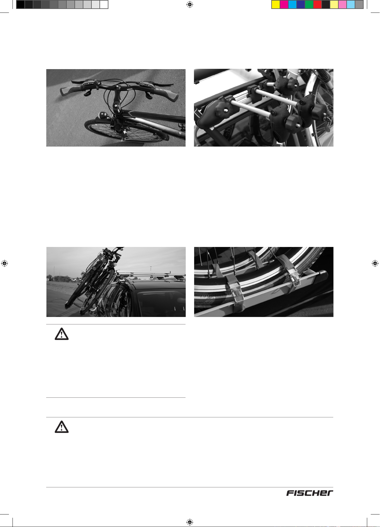
12e étape
Chargement des bicyclettes
1. Lors du chargement de 2 vélos : tournez
le guidon avant de charger la bicyclette
interne. Chargement avec guidon vers la
droite, guidon de la bicyclette à tourner vers
la droite. Chargement avec guidon vers la
gauche, guidon de la bicyclette à tourner
vers la gauche. Le guidon de la bicyclette ne
doit pas toucher le toit du véhicule.
ATTENTION !
Lors du chargement de 2
bicyclettes : placez horizontalement
les longs bras de supports entre
le cadre de la première bicyclette
! Faites attention à la position de
la pédale de la première bicyclette
(pédales entre les cadres de la 2e
bicyclette).
2. Abaissez l’élément de transport, comme
décrit dans la 11e étape, sur le côté du
véhicule ; dévissez la molette du bras de
support (ne pas dévisser complètement) !
Positionnez la bicyclette sur le rail profilé
(5). Le clip du cadre sur le bras de support
pour bicyclette (1a+1b) doit être positionné
autour du tube du cadre de la bicyclette.
L‘alignement du bras de support pour
bicyclette doit passer tout droit jusqu’à
l‘élément de transport.
3. Installez pour chaque bicyclette deux
sangles de sécurité pour bicyclette (18)
autour des jantes de la roue et des rails
et arrimez bien. Les sangles de sécurité
doivent être montés vers l’extérieur.
4. Les deux bicyclettes doivent être sécurisées
avec une sangle de sécurité (21) de 5 m.
5. Levez l’ensemble grâce au système de levage
sur le toit comme décrit dans la 10e étape et
serrez les vis de sécurité (1f).
2. Si la base des barres de toit est basse, le guidon de la bicyclette extérieure doit
3. Assurez-vous que les bicyclettes ne se touchent pas ! Éventuellement des
4. Retirez toutes les structures montées sur le vélo (notamment les sièges pour
MISES EN GARDE IMPORTANTES !
1. Si une seule bicyclette est transportée, utilisez donc le rail prolé extérieur.
être aussi légèrement tourné.
ajustements sont à effectuer (p. ex. pour la selle).
enfants) avant tout chargement.
59
18092_Betriebsanleitung_D_GB_F_IT_PL.indd 59 13.02.15 11:25
Page 60
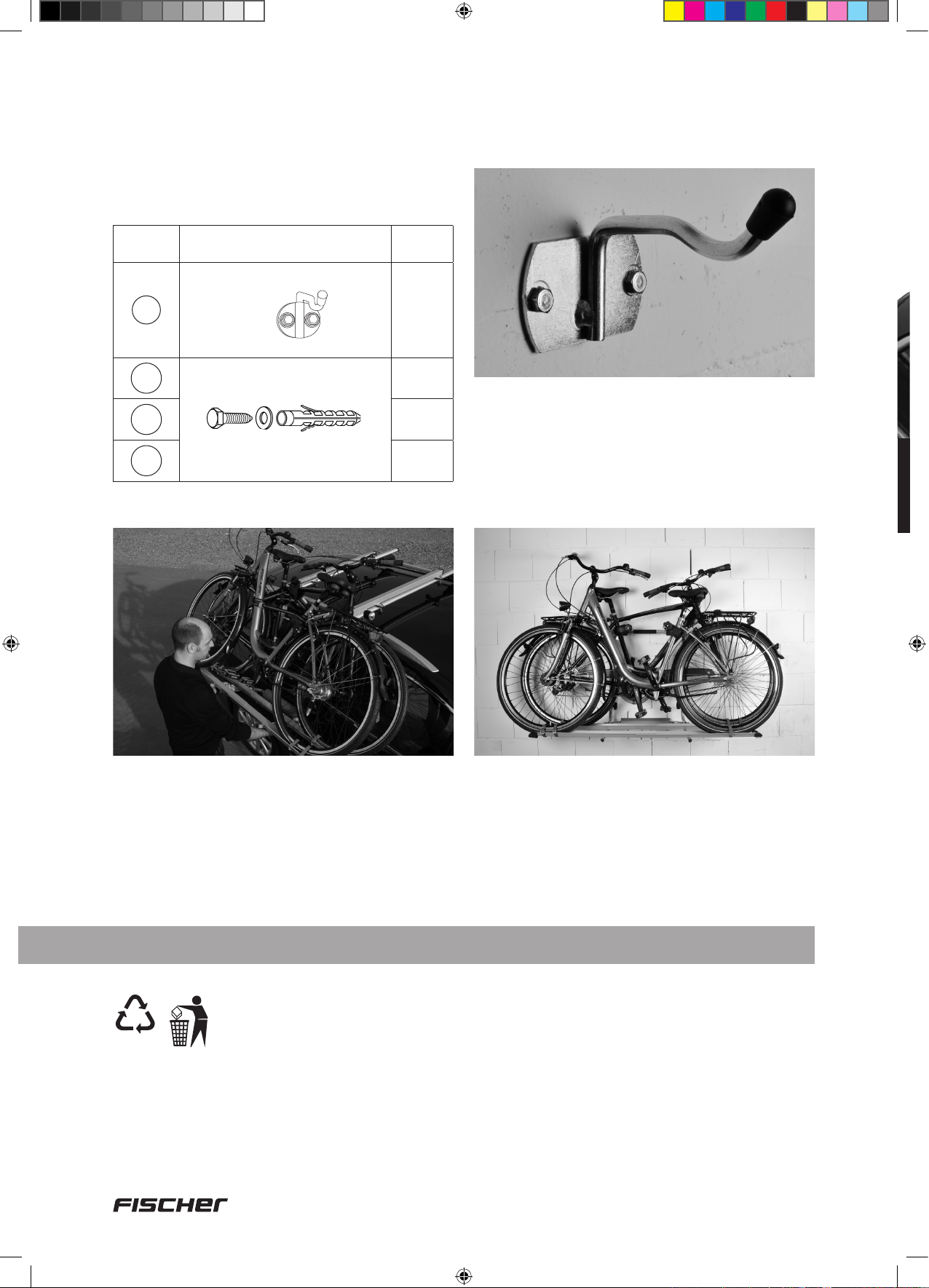
13e étape
Enlever et conserver l‘élément de transport chargé
Pour cette étape d’assemblage, vous avez
besoin des pièces suivantes :
Pièce n° Illustration Quantité
19
20a
20b
20c
Crochet
2
4
4
4
Avec les crochets à pas de vis de 6 mm
et de chevilles de 6 mm, l’élément de
transport chargé peut être suspendu à un
endroit approprié (mur de garage ou de
cave) permettant ainsi un rangement à faible
encombrement.
Abaissez l‘élément de transport, comme décrit
dans la 11e étape, sur le côté de véhicule et
avec l’aide d’une autre personne, soulevez
l’ensemble des ouvertures dans les rails de
guidage.
7. Service, fabricant
21
PAP
INTER-UNION Technohandel GmbH
Klaus-von-Klitzing-Strasse 2 · 76829 Landau · Allemagne
Tél. +49 63 41 2 84-0 · www.inter-union.de
60
18092_Betriebsanleitung_D_GB_F_IT_PL.indd 60 13.02.15 11:25
Page 61
D
Fahrradträger »Dachlift« ........................................................
– für den sicheren liegenden Transport von zwei Fahrrädern –
GB
Bicycle rack »Roof lift« .........................................................
– for safe transport of two bicycles in horizontal position –
F
Porte-vélos avec aide au »levage sur le toit« .....................
– pour le transport sûr et couché de deux bicyclettes –
IT
Portabici »Tetto auto« ........................................................... 61
– per il trasporto sicuro di 2 biciclette in posizione orizzontale –
Manuale d’uso originale Articolo N°: 18092 Versione 02/2015
21
41
Contenuto
1. Precauzioni di sicurezza ............................................................................. 62
2. Uso previsto ................................................................................................. 63
3. Strumento per il montaggio ........................................................................ 63
4. Elenco parti del portabici per tetto auto ................................................... 64
5. Informazioni generali preliminari ............................................................... 67
6. Montaggio .................................................................................................... 69
7. Assistenza, produttore ................................................................................ 80
2
PL
Bagażnik na rowery »Dachowego bagażnika« ...................
– do bezpiecznego przewożenia maks. dwóch rowerów (w pozycji leżącej) –
18092_Betriebsanleitung_D_GB_F_IT_PL.indd 61 13.02.15 11:26
81
Page 62
Gentili clienti,
Grazie per aver scelto il portabici per tetto auto FISCHER. Con questo portabici per tetto
auto potrete trasportare in modo facile e sicuro due biciclette in posizione orizzontale con
la vostra auto. Questo portabici per tetto auto viene fornito in kit di montaggio.
Prima del primo utilizzo è necessario installare il portabici per tetto auto seguendo
attentamente queste istruzioni.
1. Precauzioni di sicurezza
NOTA: Si raccomanda di leggere attentamente questo manuale prima di iniziare a montare il
portabici per tetto auto! Rispettare in particolare le istruzioni di sicurezza!
• Conservare il manuale per l’intera durata di utilizzo del prodotto
• Trasmettere il manuale al successivo proprietario e utilizzatore del prodotto
IMPORTANTE: Si prega di leggere le indicazioni del costruttore dell’auto sul carico massimo
ammissibile sul tetto. Questo portabici è stato sviluppato, costruito e testato con cura e in
conformità con gli standard di sicurezza.
• Controllare regolarmente i raccordi prima della partenza.
• Vericare i ssaggi del portabici e delle biciclette dopo 10 km e poi a intervalli regolari.
• Adattare lo stile di guida e la velocità al trasporto. Poiché in caso veicoli caricati con
portabagagli il comportamento dinamico di guida varia notevolmente, dobbiamo raccomandare
di non superare la velocità massima di 130 km/h. Non può essere assunta nessuna
responsabilità per danni che si verichino in situazioni estreme a causa di eccesso di velocità.
• Evitare viaggi a vuoto! Se non si trasportano biciclette, smontare il bici.
• Secondo il codice della strada il conducente è responsabile dell’adeguata messa in sicurezza
del carico.
• Peso a vuoto del portabici: 13,8 kg; carico massimo con due biciclette (15 kg ciascuna).
• Rispettare la capacità di carico del supporto di base. Capacità di carico = portabici+ biciclette
• Devono essere rispettate le speciche del costruttore del veicolo riguardo al carico ammesso
sul tetto. Carico sul tetto = supporto di base + portabici+ biciclette.
• Osservare il cambiamento dell’altezza totale del veicolo, soprattutto in caso di bassa altezza
libera (garage, parcheggi sotterranei, ponti). Altezza di montaggio sul supporto di base circa 60
cm.
• Il portabici e bicicletta non devono sporgere oltre il prolo del veicolo.
• Per la sicurezza durante il carico e scarico delle biciclette si consiglia di montare il portabici in
modo da poter essere abbassato sul lato passeggero.
• Conservare bene le chiavi di ricambio per la manopola con serratura in un posto separato.
• Conservare il manuale d’installazione.
• In caso di inosservanza delle istruzioni di installazione e delle informazioni di sicurezza e di
conseguenti danni al veicolo e/o alle biciclette si declina ogni responsabilità da parte del
distributore e del produttore.
Avviso
62
18092_Betriebsanleitung_D_GB_F_IT_PL.indd 62 13.02.15 11:26
Page 63

2. Uso Previsto
Il portabici per tetto auto serve a trasportare due biciclette sul tetto di un’automobile. Il portabici
per tetto auto deve essere assemblato secondo questo manuale. Durante la guida vanno
osservate le pertinenti disposizioni di legge (velocità massima consentita, peso complessivo
massimo ammesso, etc.).
3. Strumento per il montaggio
Per il montaggio è necessario il seguente strumento:
2 x Ø 10 mm
63
18092_Betriebsanleitung_D_GB_F_IT_PL.indd 63 13.02.15 11:26
Page 64

4. Elenco parti del portabici per tetto auto
Attenzione: Se si sta lavorando con queste parti, accertarsi che non vi siano bambini
piccoli nelle vicinanze. Il portabici per tetto auto contiene piccole parti che possono
essere ingerite!
Unità di base
Num.
parti
Figura Denominazione Funzione / Uso Quantità
1
1a
1b
1c
1d
1e
1c
1d
+ Staffa di supporto della bicicletta
1
Unità di base
Braccio di supporto
biciclette, 290 mm,
1 con serratura
1e
1a
1f
1e
1b
1f
1c
Braccio di supporto
biciclette, 100 mm
1d
Rullo di guida
anteriore
Rullo di guida
posteriore
Fascette
= Unità di supporto
2
Fissaggio ruota esterna
(premontato sull’unità di
base)
Fissaggio ruota interna
(premontato sull’unità di
base)
Guida unità di base
nelle rotaie di guida
(premontata)
Regolazione della
larghezza
1
2
2
2
2
2
1f
Num.
parti
2
2a
2b
2c
Fissaggio dell’unità di
Manopola
Figura Denominazione Funzione / Uso/utilisation Quantità
Staffa di supporto
della bicicletta
2a
2c
2a
2b
2c
Clip di ssaggio
Prolo in schiuma
Fascette
base ne ll e rotaie di gui da,
premontato sull’unità di
base
Inserimento biciclette
(montaggio sull’unità di
base)
Protezione supplementare
per l’unità di supporto
(premontata sull’unità di
base) contressegnata con
“L” e “R”
Imbottitura sul lato veicolo
(premontata sulla staffa di
supporto della bicicletta)
Regolazione della
larghezza
2
1
2
1
2
64
18092_Betriebsanleitung_D_GB_F_IT_PL.indd 64 13.02.15 11:26
Page 65

Num.
parti
3
3a
3b
3c
Figura Denominazione Funzione / Uso Quantità
Il rullo di supporto (3a) è sulla
destra
3c
3a
3b
Rotaia di guida
sinistra
Rullo di supporto
Piastra di base
anteriore
Piastra di base
posteriore
Guida dell’unità di supporto
/ Montaggio sul supporto
di base
Guida dell’unità di
supporto estratta
(premontata sulle rotaie
di guida)
Strato sul supporto di
base (premontato sulle
rotaie di guida)
1
2
1
1
Num.
parti
4
4a
4b
4c
Num.
parti
5
6
Figura Denominazione Funzione / Uso Quantità
Il rullo di supporto (4a) è sulla
destra
4a
4c
4b
Figura Denominazione Funzione / Uso Quantità
Rotaia di guida
destra
Rullo di supporto
Piastra di base
anteriore
Piastra di base
posteriore
Guida prolata
bicicletta 750 mm
Coperchio protettivo
per guida prolata
bicicletta
Guida dell’unità di supporto
/ Montaggio sul supporto
di base
Guida dell’unità di
supporto estratta
(premontata sulle rotaie
di guida)
Strato sul supporto di
base (premontato sulla
rotaia di guida)
Inserimento delle
biciclette, montaggio sulla
staffa di supporto della
bicicletta
Protezione bordi per guida
prolata, montaggio sulla
guida prolata bicicletta
1
2
1
1
4
4
7
8
9
10
Rondella piana,
6,5 mm, piccola
Rondella piana,
6,5 mm, grande
Vite M6 x 16 mm
Vite M6 x 35 mm
Montaggio della guida
prolata bicicletta sull’unità
di supporto (4)
Montaggio della staffa di
supporto della bicicletta
sull’unità di base (4)
Raccordo guide prolate
bicicletta (8), Montaggio
della guida prolata
bicicletta sull’unità di
supporto (4), Montaggio
delle rotaie di guida sul
supporto di base (8)
Raccordo guide prolate
bicicletta
Montaggio della guida
prolata bicicletta sull’unità
di supporto
8
20
4
4
65
18092_Betriebsanleitung_D_GB_F_IT_PL.indd 65 13.02.15 11:26
Page 66

Num.
parti
Figura Denominazione Funzione / Uso/utilisation Quantità
11
12
13
14
15
16
Vite a testa tonda
M6 x 50 mm
Vite a testa tonda
M6 x 70 mm
Dado cieco M6
Piastra di ssaggio
Prolo di protezione
per piastra di ssaggio
e piastra di base
Dado zigrinato M6
Montaggio della rotaia di guida
sul supporto di base con altezza
barre no a 35 mm
Montaggio della staffa di
supporto della bicicletta sull’
unità di base (4), Montaggio
della rotaia di guida sul supporto
di base con altezza barre
superiore a 35 mm (8)
Raccordi a vite (tranne che per
la rotaia di guida)
Montaggio sul fondo del
supporto di base
Montaggio sulla piastra di
ssaggio
Fissaggio della rotaia di guida
sul supporto di base
8
12
12
4
8
8
17
18
19
20a
20b
20c
21
Montaggio tra la staffa di
Distanziali
Cintura di sicurezza
della bicicletta,
330 mm
Gancio Aggancio dell’unità di supporto
Tasselli, 6 mm
Vite M6 x 45 mm
Rondella 6,5 mm
Cintura di sicurezza
della bicicletta, 5 m
supporto della bicicletta e
l’unità di base
Protezione biciclette sulle guide
prolate, montaggio su cerchi di
biciclette e guida prolata
Fissaggio del gancio (19)
Raccordo guide prolate
bicicletta
Protezione biciclette sulle guide
prolate
8
8
2
4
4
4
1
22
23
Chiave a bocca
doppia,10/13 mm
Chiave a brugola,
5 mm
Per tutte le viti sul portabici
(larghezza 10 mm)
Per la regolazione dei tamponi
d’arresto
1
1
66
18092_Betriebsanleitung_D_GB_F_IT_PL.indd 66 13.02.15 11:26
Page 67

L’unità di supporto può essere spostata nelle rotaie
di guida (3 + 4) in avanti e indietro.
3
1
Supporto di base
4
5. Informazioni generali preliminari
Punto 1
Il supporto di base – un requisito essenziale per il corretto funzionamento del
portabici per tetto auto
2
Innanzitutto, il supporto di base deve essere
installato sul tetto del veicolo.
Prestare attenzione! Entrambe le barre di
supporto devono essere montate parallele fra
loro e alla stessa distanza.
In molti veicoli i punti di fissaggio sono
predefiniti dal costruttore del veicolo mediante
dei contrassegni.
Per i veicoli ad esempio con grondaie o
mancorrenti sul tetto non vengono forniti dal
produttore dei punti fissi. Qui, tuttavia, la
distanza tra le barre deve essere min. 70 cm
e max. 87 cm.
Si prega di notare: Utilizzare un metro a
nastro per verificare le distanze tra le barre.
Distanza minima 70 cm, massima 87 cm
IMPORTANTE!
Montare le barre di supporto
parallele e alla stessa distanza.
70 – 87 cm
67
18092_Betriebsanleitung_D_GB_F_IT_PL.indd 67 13.02.15 11:26
Page 68

Punto 2
Preparazione del supporto per il montaggio – Separazione dell’unità di base
(1) dalle rotaie di guida (3 + 4)
Alla consegna, l’unità di base (1) è inserita nelle
rotaie di guida per proteggere i rulli di guida
(1c+1d). Prima del montaggio sul veicolo, l’unità
di base e le rotaie di guida devono essere
separate.
1. Allentare la manopola (1f) a sinistra e a
destra (non girare completamente!)
2. Premere le rotaie di guida (3+4) all’indietro
finché il rullo di guida anteriore (1c) non si
arresti nell’apertura della rotaia e sganciare
verso l’alto attraverso l’apertura.
3. Premere la rotaia di guida (3+4)
ulteriormente all’indietro finché il rullo
di guida posteriore (1d) non si arresti
nell’apertura della rotaia e sganciare l’unità
di base verso l’alto attraverso l’apertura.
1
3
1f
premere
4
2
3
68
18092_Betriebsanleitung_D_GB_F_IT_PL.indd 68 13.02.15 11:26
Page 69

6. Montaggio
Punto 3
Ora l’unità di base e le rotaie di guida
sono separate
Di fronte a voi vi sono le seguenti parti:
Num.
parti
1
3
Figura Quantità
Unità di base (1)
1
Rotaia di guida sinistra (3)
(Il rullo di supporto (3a) è sulla
destra)
3a
1
Punto 4
Premontaggio della staffa di
supporto della bicicletta (2) sull’unità
di base (1)
Per questo passaggio sono necessari i
seguenti componenti:
Num.
parti
1
2
2c
Figura Quantità
Unità di base (1)
1
Staffa di supporto della
bicicletta (2)
incl. fascette
1
Rotaia di guida destra (4)
(Il rullo di supporto (4a) è
4
sulla sinistra)
4a
1
7
12
13
17
Rondella
6,5 mm,
piccola
Vite a testa tonda M6 x 70 mm
Dado cieco M6
Distanziali
4
4
4
2
69
18092_Betriebsanleitung_D_GB_F_IT_PL.indd 69 13.02.15 11:26
Page 70

1. Prima del montaggio allentare le fascette
(2c) sulla staffa di supporto della bicicletta
(non girare completamente). Per adattare
la larghezza della staffa di supporto della
bicicletta (2) a quella dell’unità di base (1),
estrarre o introdurre nel tubo di giunzione i
tubi circolari a sinistra e a destra.
2. Inserire la vite a testa tonda (12) all’interno
dell’unità di base attraverso i fori.
3. Sul lato esterno ssare i distanziali (17) e la
staffa di supporto della bicicletta attraverso i
fori interni.
4. Sul lato opposto ssare la rondella (7) e
avvitare il dado cieco (13).
PRESTARE ATTENZIONE!
Clip di ssaggio destra - a destra
Clip di ssaggio sinistra - a sinistra
R
(particolare della clip di fissaggio destra)
1
13
13
12
2
12
7
17
7
2c
13
13
7
7
2c
17
70
18092_Betriebsanleitung_D_GB_F_IT_PL.indd 70 13.02.15 11:26
Page 71

Punto 5
Punto 6
Di fronte a voi vi è l’unità di supporto
Montaggio delle rotaie di guida (3+4)
sul supporto di base
Per questo passaggio sono necessari i
seguenti componenti:
Num.
parti
3
4
8
Figura Quantità
Rotaia di guida sinistra
1
Rotaia di guida destra
1
Rondella,
6,5 mm,
grande
8
Vite a testa tonda,
11
14
15
16
M6 x 50 mm
Piastra di
ssaggio
Prolo di protezione per
piastra di ssaggio e piastra
di base
Dado zigrinato M6
8
4
8
8
Entrambe le barre del supporto di base sono
allineate, cioè parallele e alla stessa distanza.
Si consiglia che il tetto auto venga abbassato
sul lato passeggero (SICUREZZA NELLA
CIRCOLAZIONE STRADALE). Pertanto il
montaggio delle rotaie di guida avviene dal lato
passeggero.
71
18092_Betriebsanleitung_D_GB_F_IT_PL.indd 71 13.02.15 11:26
Page 72

1. Premere i profili di protezione (15) sulla
piastra di base della rotaia di guida
(3b+c/4b+c) e la piastra di fissaggio (14).
15
3. Inserire la vite a testa tonda (11) – per
supporti di base con altezza barre superiore
a 35 mm utilizzare viti a testa tonda (12)
– da sopra nel foro delle piastre di base
(3b+c/4b+c), fissare la piastra di fissaggio
(14) da sotto con il profilo in gomma verso
l’alto e la rondella piana (8). Avvitare il
dado zigrinato (16). Avvitare saldamente
la piastra di fissaggio anteriore. Avvitare
solo leggermente le piastre di fissaggio
posteriori.
15
14
2. Posizionare la rotaia di guida (3+4) con
l’apertura in avanti sulle barre di supporto.
IMPORTANTE!
Il rullo di supporto (3a+4a) deve
essere almeno all’altezza del
bordo del tetto (non ulteriormente
all’interno).
Per supporti di base con
altezza barre superiore a
11
35 mm utilizzare viti a testa
tonda (12)
8
Supporto
16
NOTA:
Le piastre di ssaggio posteriori
vengono avvitate solo leggermente,
in modo che le rotaie di guida
possano allinearsi all’inserimento
dell’unità di supporto.
di base
Suggerimento:
Per facilitare il ssaggio delle rotaie
di guida sul supporto di base,
premontare le piastre di ssaggio
su un lato.
72
18092_Betriebsanleitung_D_GB_F_IT_PL.indd 72 13.02.15 11:26
Page 73

Punto 7
Adattamento della larghezza dell’unità di supporto a quella delle rotaie
di guida
Le rotaie di guida sono montate sul supporto
di base.
1. Allentare le viti delle fascette (1e+2c)
sull’unità di supporto (non svitare
completamente). I tubi circolari inseriti
possono essere spostati
ATTENZIONE!
La profondità minima di inserimento
è di 65 mm. Al raggiungimento
della larghezza massima appare un
marchio.
1e
1e
3. Appoggiare delicatamente l’unità di
supporto con il profilo in schiuma (2b) sul
lato del veicolo e verificare che il tubo di
giunzione sia posizionato centralmente
tra il lato sinistro e destro, eventualmente
spostare al centro. Controllare nuovamente
che la larghezza massima non venga
superata (osservare la marcatura).
4. Serrare le viti delle fascette (1e) sull’unità di
supporto.
Tubo di giunzione
2c
2. Agganciare il rullo di guida posteriore
(1d) dell’unità di supporto su un lato
nell’apertura della rotaia di guida, spostare
l’altro lato finché il rullo di guida (1d) non si
inserisca nell’apertura della rotaia di guida e
agganciare.
5. Sollevare l’unità di supporto come descritto
al punto 10 e regolare la larghezza della
staffa di supporto della bicicletta in modo
che i rulli di guida anteriori (1c) si inseriscano
nelle aperture delle rotaie di guida. Poi
serrare le viti delle fascette (2c) e abbassare
nuovamente l’unità di supporto sul lato del
veicolo come descritto al punto 11.
73
18092_Betriebsanleitung_D_GB_F_IT_PL.indd 73 13.02.15 11:26
Page 74
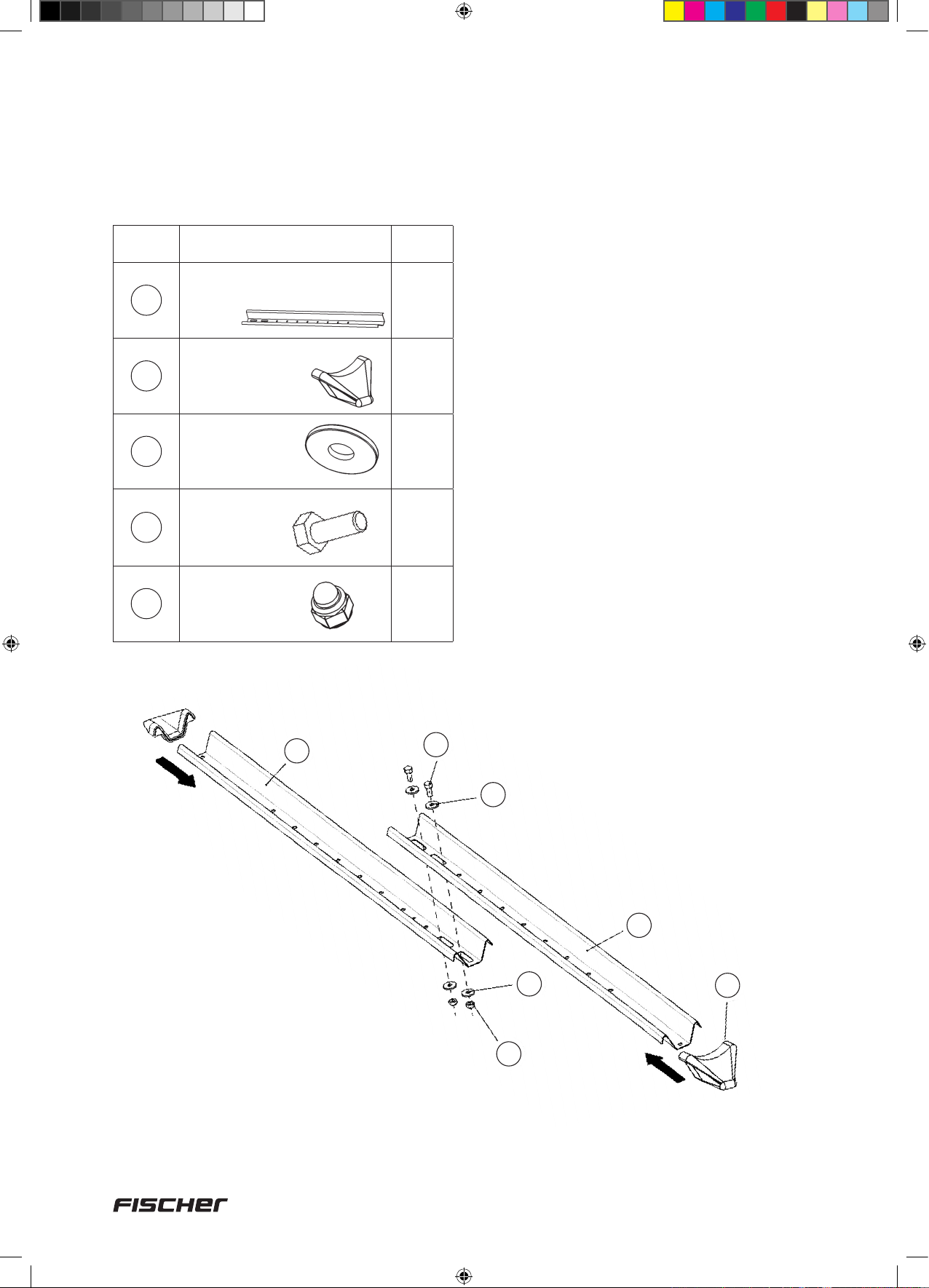
Punto 8
Unione delle guide profilate (5)
Per questo passaggio sono necessari i
seguenti componenti:
Num.
parti
5
6
8
9
13
Figura Quantità
Guida prolata bicicletta,
750 mm
Coperchio protettivo
per guida prolata
bicicletta
Rondella,
6,5 mm, grande
Vite
M6 × 16 mm
Dado cieco M6
1. Unire 2 guide profilate (5) al centro.
2. Inserire la vite (9) dapprima attraverso
la rondella (8), poi all’interno della guida
profilata attraverso il foro.
4
3. Sul lato esterno mettere la rondella (8) e
avvitare il dado cieco (13).
4. Inserire i coperchi protettivi (6) su entrambe
8
le estremità.
8
8
8
5
9
8
5
8
13
6
74
18092_Betriebsanleitung_D_GB_F_IT_PL.indd 74 13.02.15 11:26
Page 75

Punto 9
Montaggio della guida profilata (5) sull’unità di supporto
Per questo passaggio sono necessari i
seguenti componenti:
Num.
parti
5
7
8
10
13
Figura Quantità
Guida prolata bicicletta,
750 mm
Rondella,
6,5 mm,
piccola
Rondella,
6,5 mm,
grande
Vite M6 × 35 mm
2
4
4
4
Dado cieco M6
4
L’unità di supporto è adattata in larghezza e
agganciata alle rotaie di guida (3+4).
Posizione attuale:
Unità di supporto appoggiata al lato del
veicolo.
1. Fermare la guida profilata (5) sulla parte
superiore della staffa di supporto della
bicicletta.
2. Inserire la vite (10) dapprima attraverso
la rondella (8), poi dall’alto verso il basso
attraverso il foro della staffa di supporto
della bicicletta.
3. Sul lato inferiore mettere la rondella (7) e
avvitare il dado cieco (13).
NOTA:
Si noti che la sporgenza della guida
prolata è la stessa a destra e a
sinistra.
10
5
510
8
8
7
13
13
7
75
18092_Betriebsanleitung_D_GB_F_IT_PL.indd 75 13.02.15 11:26
Page 76

Punto 10
Sollevamento dell’unità di supporto sul tetto del veicolo
Per questo passaggio sono necessari i
seguenti componenti:
Num.
parti
Figura Quantità
Chiave a brugola, 5 mm
23
1
Le guide profilate sono installate. L’unità di
supporto completa può ora essere sollevata
sul tetto dell’auto.
3. Sollevare leggermente l’unità di supporto
anteriore e abbassare i rulli di guida anteriori
nell’apertura delle rotaie di guida.
1. Afferrare l’unità di supporto a destra e a
sinistra del profilo in schiuma (2b) e tirare
verso l’alto.
2. Al raggiungimento della posizione
orizzontale premere l’unità di supporto
all’indietro finché i rulli di guida anteriori (1c)
non si arrestino nelle rotaie di guida (3+4).
4. Premere l’unità di supporto ulteriormente
all’indietro finché le clip di fissaggio (2a) non
scattino da sole nell’apertura delle rotaie di
guida. Serrare la manopola (1f) a sinistra e
a destra.
5. Dopo che l’unità di supporto è stata inserita
nelle rotaie, il punto di arresto sul lato
opposto va regolato in modo esatto.
76
18092_Betriebsanleitung_D_GB_F_IT_PL.indd 76 13.02.15 11:26
Page 77
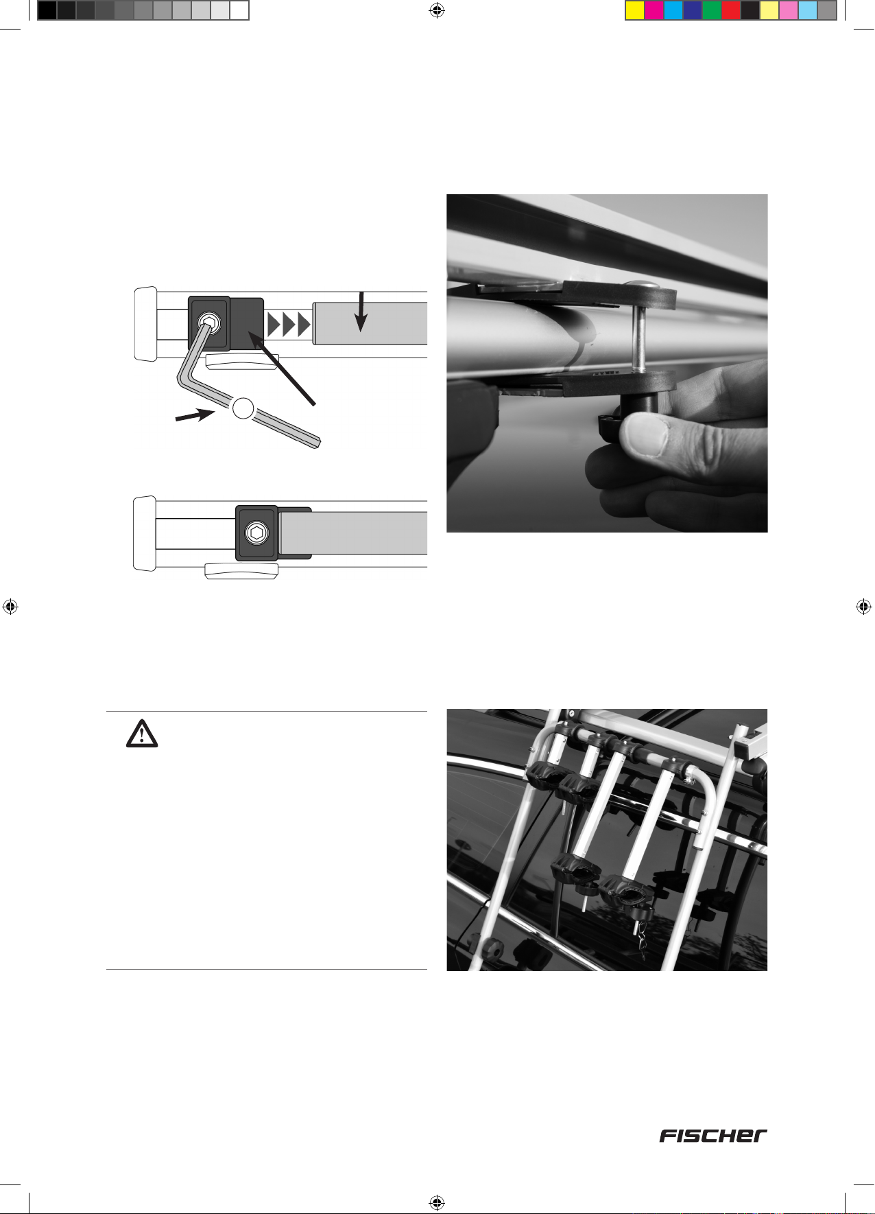
Allentare le viti a brugola (5 mm) sui tamponi
d’arresto (non svitare completamente). I tamponi
d’arresto ora possono essere spostati.
Solo dopo il montaggio iniziale:
Impostazione corretta:
Tubo circolare
dell’unità di
supporto
Chiave
a brugola
5 mm
23
Tampone
d’arresto
I tubi circolari dell’unità di supporto devono
toccare a paro con i tamponi d’arresto. Dopo
la corretta regolazione stringere di nuovo la
vite a brugola.
6. Al punto 6.3, le piastre di fissaggio posteriori
(14) sono state avvitate solo leggermente
(per l’allineamento delle rotaie di guida).
Ora le piastre di fissaggio posteriori
possono essere avvitate saldamente.
NOTA:
1. Se non vengono caricate
biciclette, prima di sollevare l’unità
di supporto mettere i due bracci
di supporto biciclette (1a+1b) in
verticale e stringere le manopole.
Così i bracci di supporto non
potranno toccare il tetto dell’auto e
i vetri laterali.
2. Se vengono caricate biciclette,
prima di sollevare l’unità di
supporto ssare le due bici con le
cinture di sicurezza (18) sui cerchi!
77
18092_Betriebsanleitung_D_GB_F_IT_PL.indd 77 13.02.15 11:26
Page 78

Punto 11
Abbassamento dell’unità di supporto dal tetto al lato del veicolo
1. Allentare la manopola (1f) a sinistra e a destra
(non girare completamente!). Afferrare l’unità
di supporto a destra e a sinistra del profilo
in schiuma (2b) e premere le clip di fissaggio
(2a) con il pollice verso il basso.
3. Tirare l’unità di supporto ulteriormente in
avanti finché i rulli di guida posteriori (1d) non
si arrestino nella rotaia di guida e abbassare
lentamente finché il profilo in schuma (2b)
non aderisca al lato del veicolo.
NOTA:
Controllare il prolo in schiuma
prima di ogni applicazione perché
sia pulito.
2. Tirare l’unità di supporto in avanti finché i
rulli di guida anteriori (1c) non si arrestino
nella rotaia di guida. Sollevare i rulli di guida
anteriori (1c) alzando delicatamente l’unità di
supporto dalle aperture della rotaia di guida,
tirare ancora in avanti e posare davanti alle
rotaie di guida.
78
18092_Betriebsanleitung_D_GB_F_IT_PL.indd 78 13.02.15 11:26
Page 79

Punto 12
Caricamento delle biciclette
1. Prima di caricare la bicicletta interna
ruotare il manubrio. Per il caricamento con
manubrio a destra, ruotare il manubrio della
bicicletta verso destra. Per il caricamento
con manubrio a sinistra, ruotare il manubrio
della bicicletta verso sinistra. Il manubrio
della bicicletta non deve toccare il tetto
dell’auto!
ATTENZIONE!
Per il caricamento di 2 biciclette:
Mettere in orizzontale i bracci di
supporto lunghi in mezzo al telaio
della prima bicicletta! Osservare la
posizione del pedale della prima
bicicletta (Pedali in mezzo al telaio
della 2° bicicletta).
2. Abbassare l’unità di supporto sul lato del
veicolo come descritto al punto 11, allentare
la manopola sul braccio di supporto bici
(non svitare completamente!) e mettere la
bicicletta nella guida profilata (5). La clip del
telaio sul braccio di supporto della bicicletta
(1a+1b) deve fare presa sul tubo del
telaio della bicicletta. La fuga del braccio
di supporto della bicicletta dovrebbe
procedere dritta fino all’unità di supporto.
3. Mettere due cinture di sicurezza per biciclette
(18) intorno al cerchio e alla guida profilata
e stringere. Le cinture di sicurezza devono
essere rivolte verso l’esterno.
4. Fissare entrambe le biciclette con la cintura
di sicurezza (21).
5. Sollevare il tetto auto come al punto 10 e
serrare le viti di bloccaggio (1f).
2. Per supporti di base bassi, eventualmente il manubrio va ruotato leggermente
3. Si noti che le biciclette non si toccano! Eventualmente vanno effettuate regolazioni
4. Rimuovere tutte le strutture montate sulla bicicletta (come ad esempio i sedili per
NOTE IMPORTANTI!
1. Se viene trasportata solo una bicicletta, utilizzare la guida profilata esterna.
anche per la bicicletta esterna.
appropriate (ad es. per la sella).
bambini) prima di caricare.
79
18092_Betriebsanleitung_D_GB_F_IT_PL.indd 79 13.02.15 11:26
Page 80

Punto 13
Rimozione e conservazione dell’unità di supporto caricata
Per questo passaggio sono necessari i
seguenti componenti:
Num.
parti
19
20a
20b
20c
Figura Quantità
Gancio
2
4
4
4
Con i ganci a vite da 6 mm e i tasselli da 6 mm
in dotazione, l’unità di supporto caricata può
essere appesa in un luogo adatto (parete della
cantina o del garage) per risparmiare spazio.
Abbassare l’unità di supporto sul lato del
veicolo come descritto al punto 11 e con l’aiuto
di un’altra persona sollevarla dalle aperture
nelle rotaie di guida.
7. Assistenza, produttore
21
PAP
INTER-UNION Technohandel GmbH
Klaus-von-Klitzing-Strasse 2 · 76829 Landau · Germany
Tél. +49 63 41 2 84-0 · www.inter-union.de
80
18092_Betriebsanleitung_D_GB_F_IT_PL.indd 80 13.02.15 11:26
Page 81

D
Fahrradträger »Dachlift« ........................................................
– für den sicheren liegenden Transport von zwei Fahrrädern –
GB
Bicycle rack »Roof lift« .........................................................
– for safe transport of two bicycles in horizontal position –
FR
Porte-vélos avec aide au »levage sur le toit« .....................
– pour le transport sûr et couché de deux bicyclettes –
IT
Portabici »Tetto auto« ........................................................... 61
– per il trasporto sicuro di 2 biciclette in posizione orizzontale –
PL
Bagażnik na rowery »Dachowego bagażnika« ...................
– do bezpiecznego przewożenia maks. dwóch rowerów (w pozycji leżącej) –
Tłumaczenie oryginalnej instrukcji obsługi nr art.: 18092 – 01/2015
21
41
81
Zawartość
1. Wskazówki dotyczące bezpieczeństwa użytkowania ............................. 82
2. Użytkowanie zgodne z przeznaczeniem ................................................... 83
3. Narzędzia potrzebne do montażu .............................................................. 83
4. Wykaz części dachowego bagażnika rowerowego ................................. 84
5. Informacje ogólne ........................................................................................ 87
6. Montaż............................................................................................................ 89
7. Serwis, producent ...................................................................................... 100
2
18092_Betriebsanleitung_D_GB_F_IT_PL.indd 81 13.02.15 11:26
Page 82

Drodzy Klienci,
Dziękujemy za zakup dachowego bagażnika rowerowego firmy FISCHER. Dzięki temu
bagażnikowi mogą Państwo w łatwy i bezpieczny sposób przewozić rowery samochodem.
Jednocześnie wolno przewozić maksymalnie dwa rowery zamocowane w pozycji leżącej.
Niniejszy dachowy bagażnik do przewożenia rowerów dostarczany jest jako zestaw
przeznaczony do złożenia.
Przed pierwszym użyciem konieczne jest dokładne zmontowanie bagażnika zgodnie ze
wskazówkami podanymi w niniejszej instrukcji obsługi.
1. Wskazówki dotyczące bezpieczeństwa użytkowania
WSKAZÓWKA: Przed rozpoczęciem montażu dachowego bagażnika na rowery należy
uważnie przeczytać niniejszą instrukcję obsługi! W szczególności należy przestrzegać instrukcji
dotyczących bezpieczeństwa!
• Instrukcję obsługi należy przechowywać przez cały okres użytkowania produktu
• Instrukcję obsługi należy przekazać wraz z produktem kolejnemu właścicielowi lub
użytkownikowi
WAŻNE: Należy przestrzegać maksymalnego dopuszczalnego obciążenia dachu podanego
przez producenta pojazdu. Ten bagażnik rowerowy został zaprojektowany, zbudowany i
przetestowany z należytą starannością oraz zgodnie z wszelkimi normami bezpieczeństwa.
• Przed wyruszeniem w drogę należy zawsze sprawdzić połączenia śrubowe.
• Po 10 km jazdy, a następnie w regularnych odstępach należy sprawdzać mocowanie
bagażnika oraz rowerów.
• Przestrzegać przepisów drogowych oraz ograniczeń prędkości. Należy powstrzymać się od
dynamicznego stylu jazdy przy mocno obciążonym bagażniku. Nie zalecamy przekraczania
prędkości 130 km/h. Nie ponosimy odpowiedzialności za szkody powstałe w sytuacjach
ekstremalnych wynikających z przekroczenia dozwolonej prędkości.
• Unikać jazdy z niezaładowanym bagażnikiem! Bagażnik należy zdjąć, jeśli nie są przewożone
żadne rowery.
• Zgodnie z zasadami ruchu drogowego kierowca jest odpowiedzialny za prawidłowe
zabezpieczenie przewożonego ładunku.
• Ciężar własny bagażnika rowerowego: 13,8 kg; dozwolone obciążenie w postaci maks. dwóch
rowerów (15 kg każdy).
• Należy wziąć pod uwagę nośność podstawy nośnej. Obciążenie = bagażnik rowerowy +
rowery
• Należy przestrzegać zaleceń producenta pojazdu dotyczących dopuszczalnego obciążenia.
Obciążenie dachu = podstawa nośna + bagażnik rowerowy + rowery.
• Należy wziąć pod uwagę zmianę całkowitej wysokości pojazdu, zwłaszcza w miejscach o
niskim prześwicie (takich jak garaże, parkingi podziemne, mosty). Wysokość konstrukcji na
podstawie nośnej wynosi ok. 60 cm.
• Bagażnik oraz rowery nie mogą wystawać poza zewnętrzne krawędzie pojazdu.
• W celu zapewnienia własnego bezpieczeństwa podczas załadunku i rozładunku rowerów,
bagażnik należy zamontować w taki sposób, aby można było go opuszczać po stronie
pasażera.
Ostrzeżenie
82
18092_Betriebsanleitung_D_GB_F_IT_PL.indd 82 13.02.15 11:26
Page 83

• Zapasowe kluczyki do zamykanego pokrętła należy przechowywać oddzielnie, w bezpiecznym
miejscu.
• Przestrzegać wskazówek dotyczących montażu.
• Producent oraz dystrybutor wyrobu nie ponoszą odpowiedzialności za uszkodzenia pojazdu
i/lub rowerów wynikłe z nieprzestrzegania wskazówek dotyczących montażu oraz instrukcji
bezpieczeństwa.
2. Użytkowanie zgodne z przeznaczeniem
Dachowy bagażnik rowerowy służy do przewożenia maksymalnie dwóch rowerów na dachu
pojazdu samochodowego. Dachowy bagażnik rowerowy należy zamontować zgodnie z niniejszą
instrukcją obsługi. Podczas jazdy należy przestrzegać obowiązujących przepisów (ograniczeń
prędkości, dopuszczalnego ciężaru całkowitego itp.).
3. Narzędzia potrzebne do montażu
Do montażu potrzebne są następujące narzędzia:
2 x Ø 10 mm
83
18092_Betriebsanleitung_D_GB_F_IT_PL.indd 83 13.02.15 11:26
Page 84

4. Wykaz części dachowego bagażnika rowerowego
Uwaga: Podczas pracy z tymi elementami należy dopilnować, aby w pobliżu nie
znajdowały się dzieci. Dachowy bagażnik rowerowy zawiera małe części, które mogą
zostać połknięte!
Jednostka podstawowa
Nr części Rysunek Opis Funkcja/zastosowanie Liczba
1
1a
1b
1c
1d
1c
1d
1e
1a
1f
1e
1b
1f
1c
+ Uchwyt rowerowy
1
Jednostka bazowa
Ramię z uchwytem
na rower 1x, 290 mm,
zamykane
Ramię z uchwytem
na rower, 100 mm
1d
Rolka prowadząca
przednia
Rolka prowadząca
tylna
= bagażnik
2
Mocowanie koła po
stronie zewnętrznej
(wstępnie zamontowane
na jednostce bazowej)
Mocowanie koła po stronie
wewnętrznej (wstępnie
zamontowane na
jednostce bazowej)
Prowadzi jednostkę
bazową w szynach
prowadzących (wstępnie
zamontowana)
1
2
2
2
2
1e
1f
Nr części Rysunek Opis Funkcja/zastosowanie Liczba
2
2a
2a
2c
2a
2b
2c
2b
Zacisk Regulacja szerokości
Zabezpieczanie
jednostki bazowej w
Pokrętło
Uchwyt rowerowy
Zacisk
zabezpieczający
Profil wykonany z
pianki z tworzywa
sztucznego
s z y n a c h p r o w a d z ą c y c h ,
wstępnie zamontowane
na jednostce bazowej
Mocowanie rowerów
(montaż na jednostce
bazowej)
Dodatkowe
zabezpieczenie bagażnika
(wstępnie zamocowane
na jednostce bazowej) z
oznaczeniami „L” (lewy)
oraz „R” (prawy)
Podkładka po stronie
pojazdu (wstępnie
zamocowana na uchwycie
rowerowym)
2
2
1
2
1
2c
Zacisk Regulacja szerokości
2
84
18092_Betriebsanleitung_D_GB_F_IT_PL.indd 84 13.02.15 11:26
Page 85

Nr części Rysunek Opis Funkcja/zastosowanie Liczba
3
3a
3b
3c
Nr części Rysunek Opis Funkcja/zastosowanie Liczba
4
4a
4b
4c
Krążek podtrzymujący (3a) po
prawej stronie
3b
3a
Krążek podtrzymujący (4a) po
prawej stronie
4a
4b
3c
4c
Szyna prowadząca
lewa
Krążek
podtrzymujący
Przednia płyta
podstawy
Tylna płyta podstawy
Szyna prowadząca
prawa
Krążek
podtrzymujący
Przednia płyta
podstawy
Tylna płyta podstawy
Prowadnik bagażnika/
montaż na podstawie
nośnej
Prowadnik rozłożonego
bagażnika (wstępnie
zamontowany na szynie
prowadzącej)
Podkładka na podstawie nośnej (uprzednio
zamontowana na szynie
prowadzącej)
Prowadnik bagażnika/
montaż na podstawie
nośnej
Prowadnik rozłożonego
bagażnika (wstępnie
zamontowany na szynie
prowadzącej)
Podkładka na podstawie
nośnej (uprzednio
zamontowana na szynie
prowadzącej)
1
2
1
1
1
2
1
1
Nr części Rysunek Opis Funkcja/zastosowanie Liczba
5
6
7
8
9
Profilowana szyna na
rower 750 mm
Osłona ochronna na
profilowaną szynę na
rower
Podkładka mała,
6,5 mm
Podkładka duża,
6,5 mm
Śruba M6 x 16 mm
Do mocowania rowerów,
montaż na uchwycie
rowerowym
Zabezpieczenie krawędzi
profilowanej szyny, montaż
na profilowanej szynie
rowerowej
Mocowanie profilowanej
szyny rowerowej na
bagażniku (4x), Mocowanie
uchwytu rowerowego na
jednostce bazowej (4x)
Łączenie profilowanych
szyn rowerowych (8x),
Mocowanie profilowanych
szyn rowerowych na
bagażniku (4x), Mocowanie
szyn prowadzących na
podstawie nośnej (8x)
Łączenie profilowanych
szyn rowerowych
4
4
8
20
4
Mocowanie profilowanych
10
Śruba M6 x 35 mm
szyn rowerowych na
bagażniku
4
85
18092_Betriebsanleitung_D_GB_F_IT_PL.indd 85 13.02.15 11:26
Page 86

Nr części Rysunek Opis Funkcja/zastosowanie Liczba
11
12
13
14
15
16
Śruba podsadzana
M6 x 50 mm
Śruba podsadzana
M6 x 70 mm
Nakrętka kołpakowa M6Połączenia śrubowe (z wyjątkiem
Płyta montażowa
Profil ochronny do
płyty montażowej oraz
płyty bazowej
Nakrętka radełkowana M6Mocowanie szyny prowadzącej
Mocowanie szyny prowadzącej
na podstawie nośnej z belkami o
wysokości do 35 mm
Mocowanie uchwytu rowerowego
na jednostce bazowej (4x),
Mocowanie szyny prowadzącej
na podstawie nośnej z belkami o
wysokości większej niż 35 mm (8x)
szyny prowadzącej)
Mocowanie na spodniej stronie
podstawy nośnej
Mocowanie na płycie
montażowej
na podstawie nośnej
8
12
12
4
8
8
17
18
19
20a
20b
20c
21
Uchwyt odstępowy
Pas zabezpieczający
rower, 330 mm
Hak Zawieszanie bagażnika
Kołek, 6 mm
Śruba M6 x 45 mm
Podkładka 6,5 mm
Pas zabezpieczający
rower, 5 m
Mocowanie między uchwytem
rowerowym i jednostką bazową
Mocowanie rowerów do
profilowanych szyn, zakładany
na felgi kół oraz na profilowane
szyny
Mocowanie haka (19), łączenie
profilowanych szyn rowerowych
Mocowanie rowerów do
profilowanych szyn
8
8
2
4
4
4
1
Do wszystkich połączeń
22
23
Dwustronny klucz
płaski, 10/13 mm
Klucz imbusowy,
5 mm
śrubowych na bagażniku
rowerowym (szerokość klucza
10 mm)
Do regulowania odbojników
1
1
86
18092_Betriebsanleitung_D_GB_F_IT_PL.indd 86 13.02.15 11:26
Page 87

Bagażnik można przesuwać do przodu i do
tyłu po szynach prowadzących (3+4).
3
1
Podstawa nośna
4
5. Informacje ogólne
Krok 1
Podstawa nośna — element niezbędny, aby zagwarantować prawidłowe
funkcjonowanie dachowego bagażnika rowerowego
2
W pierwszej kolejności należy zamontować
podstawę nośną na dachu pojazdu.
Bezwzględnie przestrzegać! Belki bagażnika
muszą być względem siebie równoległe.
Odległość między nimi musi być identyczna
na całej ich długości. Wiele pojazdów posiada
punkty montażowe, które wyznaczył producent
pojazdu.
Pojazdy z rynnami lub bagażnikiem dachowym
nie posiadają punków montażowych
wyznaczonych przez producenta. W takich
przypadkach odstęp między belkami musi
wynosić minimalnie 70 cm i maksymalnie 87 cm.
Wskazówka: aby sprawdzić odstępy między
belkami, należy użyć metrówki.
Odstęp minimalnie 70 cm i maksymalnie
87 cm
WAŻNE!
Belki bagażnika należy
zamontować równolegle, tak aby
odległość między nimi była taka
sama na całej długości.
70 – 87 cm
87
18092_Betriebsanleitung_D_GB_F_IT_PL.indd 87 13.02.15 11:26
Page 88

Krok 2
Przygotowanie bagażnika do montażu – zdejmowanie jednostki bazowej (1)
z szyn prowadzących (3+4)
W celu zabezpieczenia rolek prowadzących (1c
+ 1d) jednostka bazowa (1) została nasunięta
na szyny prowadzące na czas dostawy. Przed
montażem na pojeździe jednostkę bazową
należy zdjąć z szyn prowadzących.
1. Poluzować pokrętła (1f) po lewej i prawej
stronie (nie odkręcać całkowicie!).
2. Szyny prowadzące (3+4) popchnąć do tyłu,
aż przednia rolka prowadząca (1c) wysunie
się z otworu.
3. Szyny prowadzące (3+4) należy dalej
przesuwać do tyłu, aż tylna rolka
prowadząca (1d) również wysunie się z
otworu.
1
3
1f
naciskać
4
2
3
88
18092_Betriebsanleitung_D_GB_F_IT_PL.indd 88 13.02.15 11:26
Page 89

6. Montaż
Krok 3
Teraz jednostka bazowa oraz szyny
prowadzące są od siebie oddzielone
Części powinny wyglądać w następujący
sposób:
Nr części Rysunek Liczba
Jednostka bazowa (1)
1
Szyna prowadząca lewa (3)
(krążek podtrzymujący (3a)
znajduje się po prawej stronie)
3
3a
1
1
Krok 4
Wstępne mocowanie bagażnika
rowerowego (2) do jednostki
bazowej (1)
Na tym etapie montażu potrzebne będą
następujące części:
Nr części Rysunek Liczba
Jednostka bazowa (1)
1
Uchwyt rowerowy (2) z
zaciskiem
2
2c
1
1
Szyna prowadząca prawa (4)
(krążek podtrzymujący (4a)
znajduje się po lewej stronie)
4
1
7
4a
12
13
17
Podkładka,
6,5 mm,
mała
Śruba podsadzana
M6 x 70 mm
Nakrętka
kołpakowa M6
Uchwyt
odstępowy
4
4
4
2
89
18092_Betriebsanleitung_D_GB_F_IT_PL.indd 89 13.02.15 11:26
Page 90
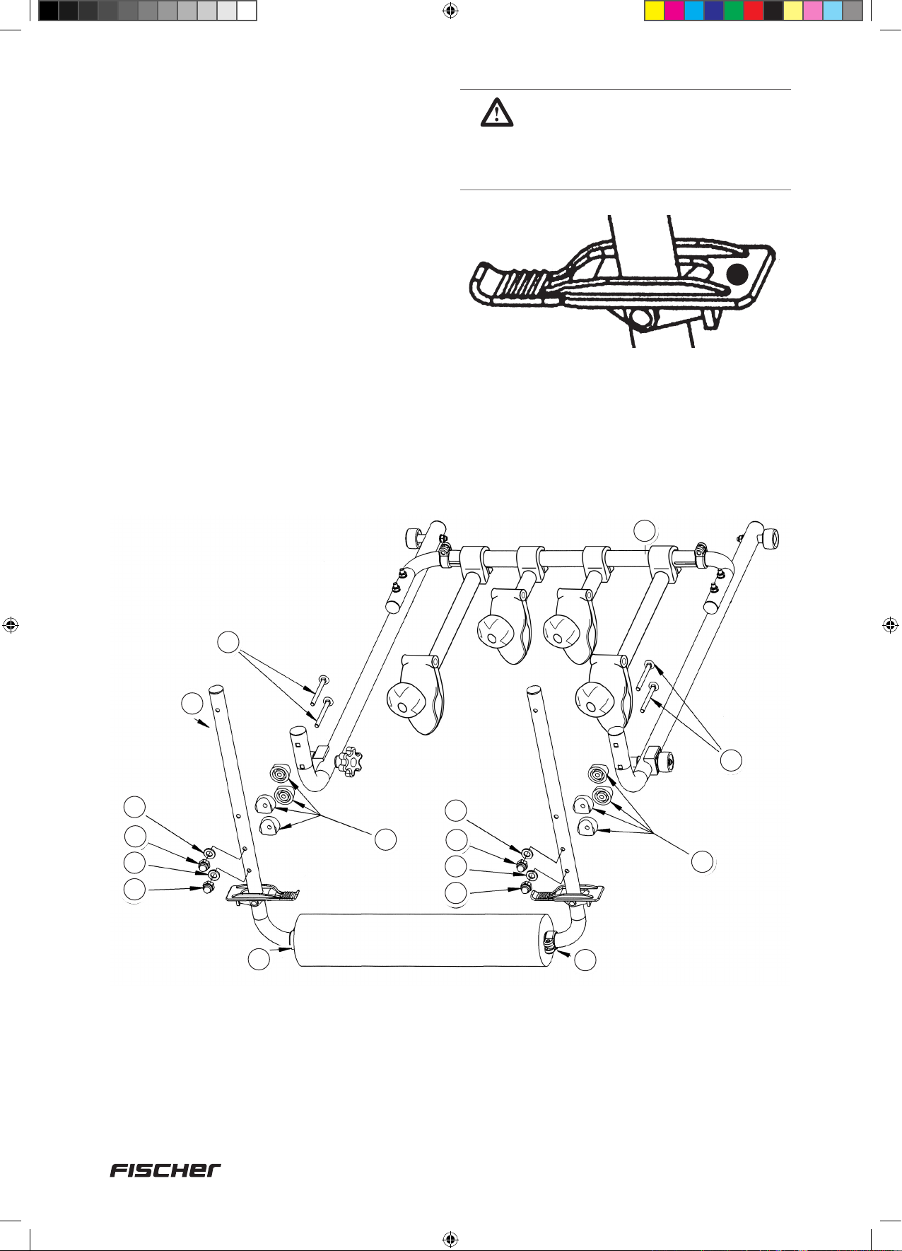
1. Przed montażem należy poluzować zacisk
(2c) na uchwycie rowerowym (nie odkręcać
całkowicie). Aby dopasować szerokość
uchwytu rowerowego (2) do szerokości
jednostki bazowej (1), rury zamocowane po
lewej i prawej stronie należy zdjąć z rury
łączącej.
2. Po wewnętrznej stronie jednostki bazowej
wprowadzić w otwór śrubę podsadzaną (12).
3. W otworach znajdujących się po
wewnętrznej stronie należy osadzić
zewnętrzny uchwyt odstępowy (17) oraz
uchwyt rowerowy.
4. Po przeciwnej stronie nałożyć podkładkę (7)
i przykręcić nakrętkę kołpakową (13).
BEZWZGLĘDNIE
PRZESTRZEGAĆ!
Prawy zacisk zabezpieczający
– po prawej; Lewy zacisk
zabezpieczający – po lewej
(Rysunek przedstawia prawy zacisk
zabezpieczający)
R
13
13
1
12
2
12
7
17
7
13
13
7
7
17
2c
2c
90
18092_Betriebsanleitung_D_GB_F_IT_PL.indd 90 13.02.15 11:26
Page 91
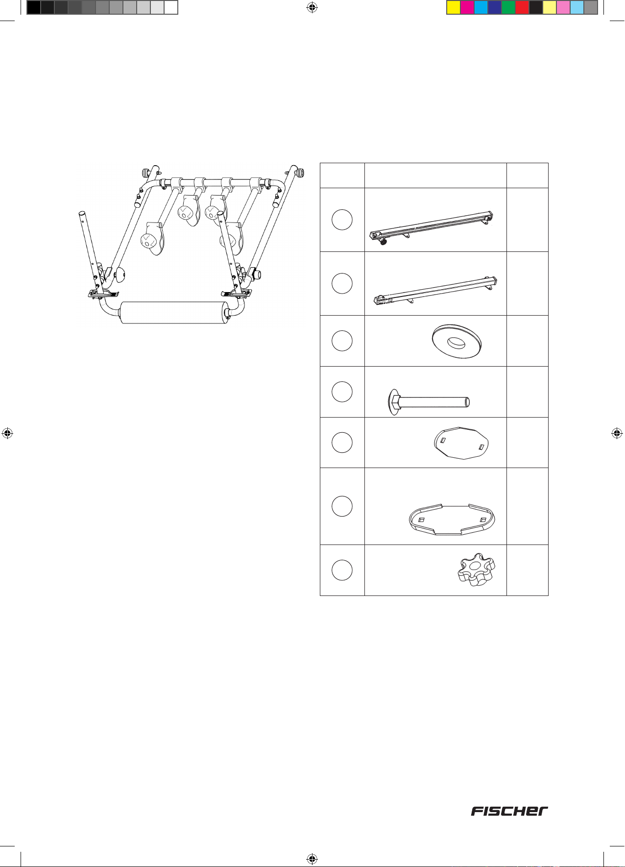
Krok 5
Krok 6
Bagażnik na tym etapie wygląda w
następujący sposób
Mocowanie szyn prowadzących (3+4)
na podstawie nośnej
Na tym etapie montażu potrzebne będą
następujące części:
Nr części Rysunek Liczba
Szyna prowadząca lewa
3
Szyna prowadząca prawa
4
Podkładka,
8
6,5 mm,
duża
1
1
8
Śruba podsadzana,
11
14
15
16
M6 x 50 mm
Płyta
mocująca
Profil ochronny do płyty
mocującej i płyty bazowej
Nakrętka
kołpakowa M6
8
4
8
8
Belki bagażnika muszą być względem siebie
równoległe, tzn. odległość między nimi musi
być taka sama na całej ich długości. Zaleca
się, aby opuszczać bagażnik dachowy po
stronie pasażera (W CELU ZAPEWNIENIA
BEZPIECZEŃSTWA W RUCHU
DROGOWYM). W związku z tym szyny
prowadzące należy zamontować właśnie po
stronie pasażera.
91
18092_Betriebsanleitung_D_GB_F_IT_PL.indd 91 13.02.15 11:26
Page 92

1. Profil ochronny (15) należy docisnąć do płyty
bazowej szyny prowadzącej (3b+c/4b+c)
oraz do płyty mocującej (14).
15
3. Śruba podsadzana (11) – niezbędna w
przypadku mocowania do podstawy nośnej
z belkami o wysokości powyżej 35 mm
Sposób użycia śrub podsadzanych (12)
– wsunąć od góry w otwory w płycie
bazowej (3b+c/4b+c). Pod spodem należy
umieścić płytę montażową (14) z gumowym
profilem, docisnąć do góry i zabezpieczyć
podkładką (8). Przykręcić nakrętkę (16)
kołpakową. Mocno przykręcić przednią
płytę montażową. Tylną płytę montażową
należy natomiast przykręcić luźno.
15
14
2. Szyny prowadzące (3+4) z otworami
skierowanymi do przodu należy nasunąć na
belki bagażnika.
W przypadku podstaw
nośnych z belkami o
wysokości powyżej 35 mm
11
należy zastosować śruby
podsadzane (12).
8
Podstawa
16
WSKAZÓWKA:
Tylną płytę montażową należy
nośna
przykręcić luźno, aby możliwe było
wyrównanie szyn prowadzących
podczas nasuwania ich na
bagażnik.
92
WAŻNE!
Krążek podtrzymujący (3a+4a)
musi znajdować się co najmniej
na wysokości krawędzi dachu
(nie przesuwać go bardziej do
wewnątrz).
R A D A :
Aby ułatwić mocowanie szyn
prowadzących na podstawie
nośnej, płytę mocującą należy
wstępnie zamontować jedynie po
jednej stronie.
18092_Betriebsanleitung_D_GB_F_IT_PL.indd 92 13.02.15 11:26
Page 93
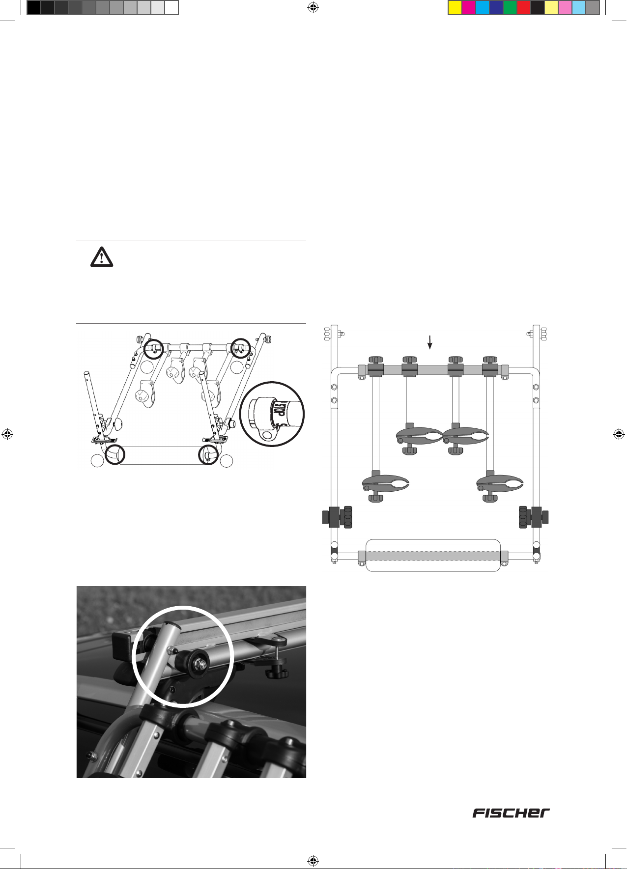
Krok 7
Dopasowywanie szerokości bagażnika do szerokości szyn prowadzących.
Szyny prowadzące należy zamontować na
podstawie nośnej.
1. Poluzować śruby zaciskowe (1e+2c)
przy bagażniku (nie należy odkręcać ich
całkowicie). Po poluzowaniu śrub możliwe
będzie przesuwanie rur.
U W A G A !
Minimalna głębokość, na jaką
szyny muszą pozostać wsunięte
wynosi 65 mm. Po osiągnięciu
maksymalnej szerokości widoczne
będzie oznaczenie.
1e
1e
3. Bagażnik należy ostrożnie oprzeć na
profilu z pianki z tworzywa sztucznego (2b)
po stronie pojazdu i upewnić się, że rura
łącząca znajduje się po środku, między lewą
i prawą stroną. W razie potrzeby przesunąć
rurę tak, aby znalazła się na środku.
Ponownie upewnić się, że nie przekroczono
maksymalnej dozwolonej szerokości
(przestrzegać oznaczeń).
4. Mocno przykręcić śruby zaciskowe (1e+2c)
do bagażnika.
Rura łącząca
2c
2. Tylną rolkę prowadzącą (1d) bagażnika
należy po jednej stronie dopasować do
otworu szyny prowadzącej. W tym celu
należy przesuwać rolkę prowadzącą (1d), aż
wyrówna się z otworem szyny prowadzącej i
tym samym się w nim osadzi.
5. Podnieść bagażnik w sposób opisany
w Kroku 10 i wyregulować szerokość
uchwytu rowerowego tak, aby przednia
rolka prowadząca (1c) dopasowała się do
otworu szyny prowadzącej. Następnie należy
dokręcić śruby dociskowe (2c) i ponownie
podnieść bagażnik, umieszczając go na
dachu pojazdu w sposób opisany w Kroku 11.
93
18092_Betriebsanleitung_D_GB_F_IT_PL.indd 93 13.02.15 11:26
Page 94

Krok 8
Montaż szyn profilowanych (5)
Na tym etapie montażu potrzebne będą
następujące części:
Nr części Rysunek Liczba
Profilowana szyna rowerowa,
5
6
8
9
13
750 mm
Osłona ochronna na
profilowaną szynę
rowerową
Podkładka,
6,5 mm, duża
Śruba
M6 × 16 mm
Nakrętka
kołpakowa M6
4
8
8
8
8
1. Nałożyć na siebie 2 profilowane szyny (5).
2. Śrubę (9) włożyć w podkładkę (8), a
następnie wsunąć w otwór znajdujący się po
wewnętrznej stronie profilowanej szyny.
3. Po zewnętrznej stronie umieścić kolejną
podkładkę (8) i przykręcić nakrętkę
kołpakową (13).
4. Na oba końce założyć ochronne osłony (6).
5
9
8
5
8
13
6
94
18092_Betriebsanleitung_D_GB_F_IT_PL.indd 94 13.02.15 11:26
Page 95
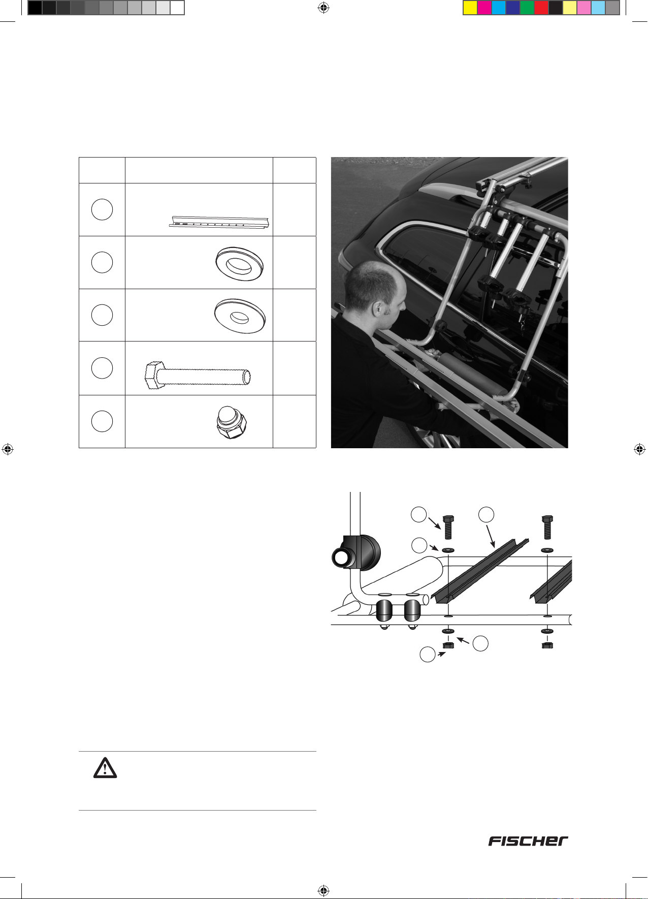
Krok 9
Mocowanie profilowanej szyny (5) na bagażniku
Na tym etapie montażu potrzebne będą
następujące elementy:
Num.
parti
5
7
8
10
13
Figura
Profilowana szyna rowerowa,
750 mm
Podkładka,
6,5 mm, mała
Podkładka,
6,5 mm, duża
Śruba M6 × 35 mm
Nakrętka
kołpakowa M6
Quantità
2
4
4
4
4
Na tym etapie szerokość bagażnika jest
już odpowiednio dopasowana, a bagażnik
odpowiednio założony na szynach
prowadzących (3+4).
Aktualne położenie:
Bagażnik opuszczony po stronie pojazdu.
1. Profilowaną szynę (5) należy umieścić na
uchwycie rowerowym.
2. Śrubę (10) włożyć w podkładkę (8), a
następnie wsunąć ją w otwór uchwytu
rowerowego.
3. Pod spodem nałożyć podkładkę (7) i
przykręcić nakrętkę kołpakową (13).
WSKAZÓWKA:
Należy dopilnować, aby odstęp
między profilowanymi szynami był
taki sam na całej długości.
10
5
510
8
8
7
13
13
7
95
18092_Betriebsanleitung_D_GB_F_IT_PL.indd 95 13.02.15 11:26
Page 96

Krok 10
Podnoszenie bagażnika na dach pojazdu
Na tym etapie montażu potrzebne będą
następujące elementy:
Nr części Rysunek Liczba
Klucz imbusowy, 5 mm
23
1
Profilowane szyny są już zamontowane. W
pełni złożony bagażnik można teraz podnieść
na dach pojazdu.
1. Bagażnik należy chwycić po obu stronach
profilu z tworzywa sztucznego (2b) i
podnieść do góry.
3. Nieznacznie podnieść przednią część
bagażnika i wsunąć przednią rolkę
prowadzącą w otwór szyny prowadzącej.
4. Przesuwać bagażnik do tyłu, aż zatrzaski
zabezpieczające (2a) zaskoczą w otworze
szyny prowadzącej. Pokrętło (1f) należy
mocno przykręcić.
2. Po uzyskaniu odpowiedniego położenia
(położenie poziome) przesunąć bagażnik
do tyłu, aż przednia rolka prowadząca (1c)
5. Po nasunięciu bagażnika na szyny punkt
oporowy musi znajdować się dokładnie po
przeciwnej stronie.
zaskoczy na szynie prowadzącej (3+4).
96
18092_Betriebsanleitung_D_GB_F_IT_PL.indd 96 13.02.15 11:26
Page 97

Poluzować śruby imbusowe (5 mm) przy
odbojniku (nie należy odkręcać ich całkowicie).
Odbojnik można teraz przesunąć.
Prawidłowy montaż:
Rura
bagażnika
Klucz
imbusowy
5 mm
23
Odbojnik
Wyłącznie podczas pierwszego montażu:
Rura bagażnika musi dokładnie zaskoczyć
przy odbojniku. Po prawidłowym ustawieniu
przykręcić śrubę imbusową.
WSKAZÓWKA:
1. Jeśli na bagażniku nie
zamocowano żadnego roweru,
przed podniesieniem bagażnika
oba ramiona uchwytu rowerowego
(1a+1b) należy ustawić w pozycji
pionowej, a następnie mocno
dokręcić pokrętła. Nie wolno
poruszać ramieniem uchwytu ani
bocznymi szynami.
2. Jeśli załadowano rowery, przed
podniesieniem bagażnika należy
zabezpieczyć oba rowery za
pomocą pasów zabezpieczających
(18). Pasy należy przymocować do
felg!
6. W kroku 6.3 tylne płyty montażowe (14)
zostały jedynie lekko przykręcone (aby
umożliwić wyrównanie szyn prowadzących).
Teraz można już dokładnie dokręcić płyty
montażowe.
97
18092_Betriebsanleitung_D_GB_F_IT_PL.indd 97 13.02.15 11:26
Page 98

Krok 11
Zdjąć bagażnik z dachu pojazdu, opuszczając go po stronie pasażera.
1. Poluzować pokrętła po lewej i prawej stronie
(1f) (nie odkręcać całkowicie!). Chwycić
bagażnik po obu stronach. Po bokach profilu
z tworzywa sztucznego (2b) znajdują się
zatrzaski zabezpieczające (2a), które należy
docisnąć do dołu kciukiem.
3. Przesuwać bagażnik do przodu, aż tylna
rolka prowadząca (1d) zaskoczy w szynie
prowadzącej. Następnie należy powoli
opuszczać bagażnik, aż profil z tworzywa
sztucznego (2b) dotknie pojazdu.
WSKAZÓWKA:
Przed każdym załadunkiem należy
sprawdzić czystość profilu z
tworzywa sztucznego.
2. Przesuwać bagażnik do przodu, aż
przednia rolka prowadząca (1c) osadzi się
w szynie prowadzącej. Wyjąć przednią
rolkę prowadzącą (1c) z otworu szyny
prowadzącej, lekko ją unosząc. Następnie
dalej przesuwać do przodu i zdjąć z szyny
prowadzącej.
98
18092_Betriebsanleitung_D_GB_F_IT_PL.indd 98 13.02.15 11:26
Page 99

Krok 12
Ładowanie rowerów
1. W przypadku ładowania 2 rowerów: Przed
załadowaniem roweru, który znajdować
się będzie na spodzie należy przekręcić
jego kierownicę. Jeśli kierownice rowerów
znajdują się po prawej stronie pojazdu,
należy przekręcić je w prawo. Jeśli
kierownice rowerów znajdują się po lewej
stronie pojazdu należy przekręcić je w lewo.
Kierownica roweru nie może dotykać dachu
pojazdu!
UWAGA!
Przy ładowaniu 2 rowerów:
Dłuższe ramię uchwytu należy
umieścić poziomo między ramami
roweru, który załadowano jako
pierwszy! Należy zwrócić uwagę
na położenie pedałów pierwszego
roweru (pedały między ramami 2.
roweru).
2. Zsunąć bagażnik w sposób opisany w Kroku
11 (po stronie pasażera). Poluzować pokrętło
przy ramieniu uchwytu rowerowego (nie
należy odkręcać całkowicie!) i umieścić rower
na profilowanych szynach (5). Zacisk na
ramę znajdujący się przy ramieniu uchwytu
rowerowego (1a+1b) należy zacisnąć na ramie
roweru. Jeśli ramię uchwytu rowerowego
odczepi się, ładunek najprawdopodobniej
spadnie.
3. Oba rowery należy zabezpieczyć pasami (18),
przywiązując felgi kół do profilowanej szyny.
Paski należy umiejscowić jak najbardziej na
zewnątrz, w miarę możliwości.
4. Oba rowery należy przymocować za pomocą
pasów (21).
5. Podnieść bagażnik dachowy w sposób
opisany w kroku 10 i dokręcić śruby
zabezpieczające (1f).
1. Jeśli przewożony będzie wyłącznie jeden rower, należy użyć zewnętrznej
2. W przypadku niskich podstaw nośnych kierownicę roweru załadowanego na
3. Należy dopilnować, aby rowery się ze sobą nie stykały! W razie potrzeby należy
4. Przed załadunkiem należy zdemontoważ zamontowane na rowerze akcesoria
WAŻNA WSKAZÓWKA!
profilowanej szyny.
wierzchu również należy przekręcić lekko do zewnątrz.
zmienić położenie niektórych części (np. siodełka).
(np. fotelik).
99
18092_Betriebsanleitung_D_GB_F_IT_PL.indd 99 13.02.15 11:26
Page 100

Krok 13
Zdejmowanie i przechowywanie bagażnika z załadowanymi rowerami
Na tym etapie montażu potrzebne będą
następujące elementy:
Nr części Rysunek Liczba
Hak
19
20a
20b
20c
2
4
Za pomocą dołączonych gwintowanych haków
4
4
6 mm i kołków rozporowych można powiesić
bagażnik w odpowiednim miejscu (np. w
piwnicy lub w garażu). Rozwiązanie to pozwala
zaoszczędzić miejsce.
100
Zdjąć bagażnik w sposób opisany w Kroku 11
(należy zsunąć go po stronie pasażera).
Z pomocą drugiej osoby wyjąć go z otworów
szyny prowadzącej.
7. Serwis, producent
21
PAP
INTER-UNION Technohandel GmbH
Klaus-von-Klitzing-Strasse 2 · 76829 Landau · Niemcy
Tél. +49 63 41 2 84-0 · www.inter-union.de
18092_Betriebsanleitung_D_GB_F_IT_PL.indd 100 13.02.15 11:26
 Loading...