

Page 1
d e velop i n g s o l u t i o n s
*09005881* BA_EN_EA14M_LCD Rev.A 09/16
*09005881*
Operating manual
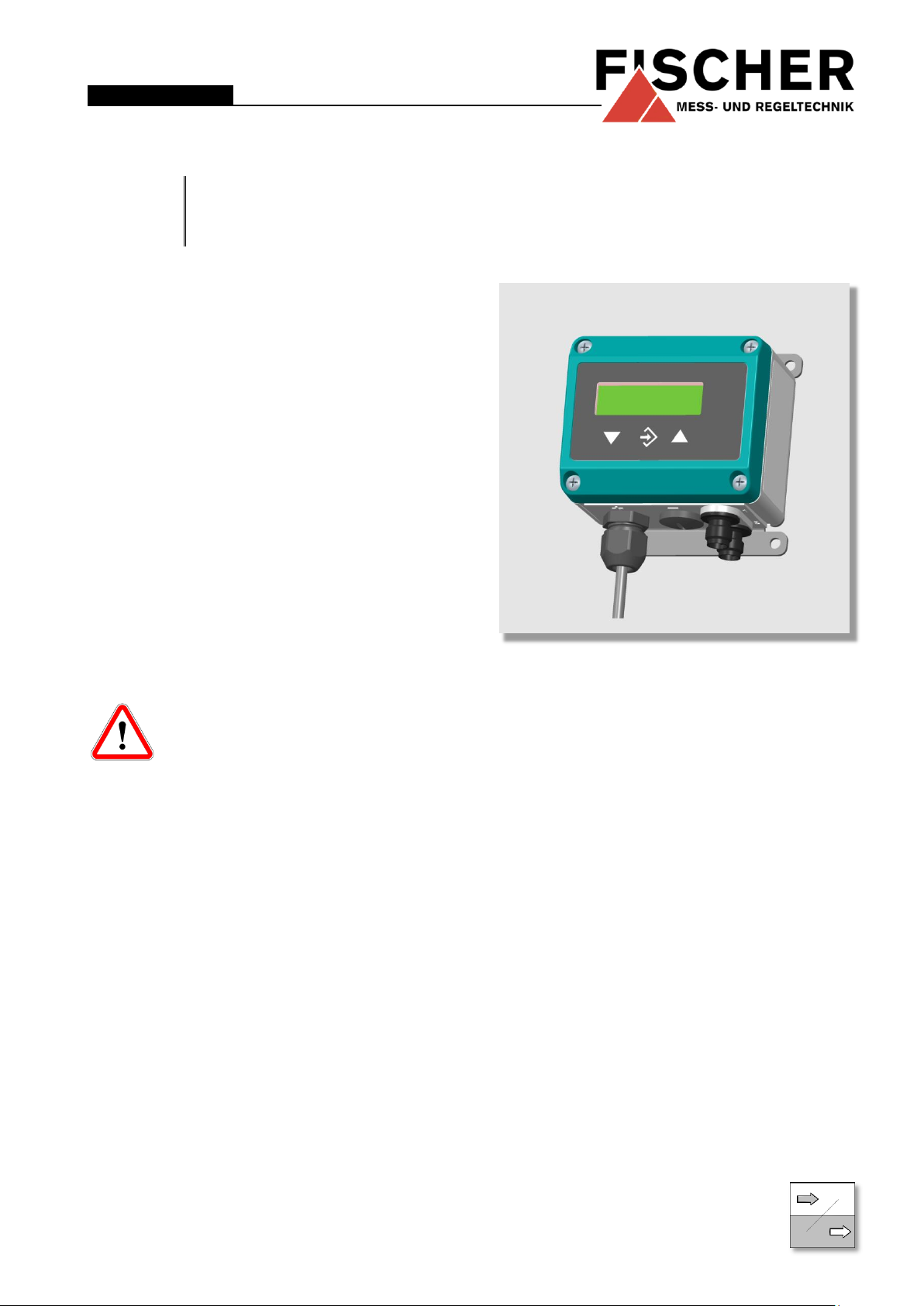
EA14M
Pressure indicator
with colour-changing LCD
Table of Contents
1 Safety guidelines
2 Application purpose
3 Product and functional description
4 Installation and assembly
5 Commissioning
6 Maintenance
7 Transportation
8 Service
9 Accessories
10 Waste Disposal
11 Technical Data
12 Dimensional drawings
13 Order Codes
14 Manufacturer's Declarations and Certificates
1 Safety guidelines
1.1 General
This operating manual contains instructions fundamental to the installation,
operation and maintenance of the de-
vice that must be observed unconditionally. It must be read by the assembler, operator
and the specialized personnel in charge of the device before it is installed and put into operation.
This operating manual is an integral part of the
product and therefore needs to be kept close to the
instrument in a place that is accessible at all times
to the responsible personnel.
The following sections, in particular instructions
about the assembly, commissioning and maintenance, contain important information, nonobservance of which could pose a threat to humans,
animals, the environment and property.
1.1 Personnel Qualification
The device may only be installed and commissioned by specialized personnel familiar with the installation, commissioning and operation of this
product.
Specialized personnel are persons who can assess
the work they have been assigned and recognize
potential dangers by virtue of their specialized train-
ing, their skills and experience and their knowledge
of the pertinent standards.
1.2 Risks due to Non-Observance of Safety Instructions
Non-observance of these safety instructions, the intended use of the device or the limit values given in
the technical specifications can be hazardous or
cause harm to persons, the environment or the
plant itself.
The supplier of the equipment will not be liable for
damage claims if this should happen.
1.3 Safety Instructions for the Operating Company and the Operator
The safety instructions governing correct operation
of the instrument must be observed. The operating
company must make them available to the installation, maintenance, inspection and operating personnel.
Dangers arising from electrical components, energy
discharged by the medium, escaping medium and
incorrect installation of the device must be eliminated. See the information in the applicable national
and international regulations.
In Germany these are the DIN EN, UVV
regulations, specific industrial guidelines
such as DVGW, Ex, GL, etc., the VDE-
Page 2
WARNING!
… indicates a potentially dangerous
situation, non-observance of which
could endanger persons, animals, the
environment or objects.
INFORMATION!
… highlights important information for
efficient and smooth operation.
TIP!
… indicates recommendations that are
not specifically necessary in certain
situations but which could be useful.
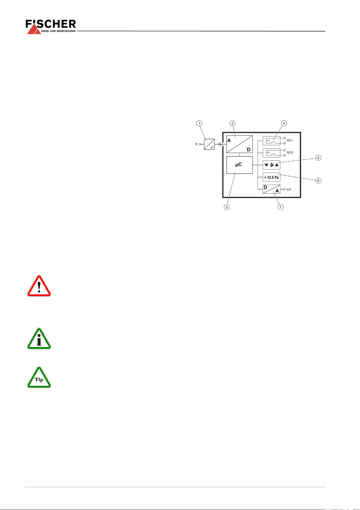
1
Transmitter
with input signal
2
Signal conversion
3
Micro-controller
4
Switch output
5
Keyboard
6
Display
7
Analogue output
regulations and the regulations of the local energy
supply companies.
1.4 Unauthorised Modification
Modifications of or other technical alterations to the
instrument by the customer are not permitted. This
also applies to replacement parts. Any modifications / alterations required must be carried out by
Fischer Mess- und Regeltechnik GmbH only.
1.5 Inadmissible Modes of Operation
The operational safety of this instrument can only
be guaranteed if it is used as intended. The instrument model must be suitable for the medium used
in the system. The limit values given in the technical
data may not be exceeded.
1.6 Safe working practices for maintenance and installation work
The safety instructions given in this operating manual, any nationally applicable regulations on accident prevention and any of the operating company's
internal work, operating and safety guidelines must
be observed.
2 Application purpose
The EA14A can be used as a transmitter and display unit for measuring pressure. The device analyses a signal (current or voltage) that originates
from an external transmitter.
3 Product and functional description
3.1 Function diagram
The operating company is responsible for ensuring
that all required maintenance, inspection and installation work is carried out by qualified specialized
personnel.
1.7 Explanation of symbols
3.2 Design and mode of operation
This device is based on an electronic analysis
switch that analyses the measuring signal of an external transmitter. The main task is to display and
analyse the measured signal. Optionally, an output
signal can be provided that is proportional to the input signal.
The external transmitter is connected to the analysis circuit using a flexible cable with plug connectors which also acts as the power supply. Only the
supplied transmitters may be connected.
4 Installation and assembly
The device is designed for installation onto flat assembly plates. For screw connection to the assembly plate, the device features four assembly bores
on its back, which can be used for Ø 3.5 mm tapping screws. Optionally, the device can be delivered
with a wall-mounting plate.
2 | 16 Page
The enclosure protection type IP 65 is only guaranteed, if a suitable power supply cable is used.
Page 3
+ Ub
Power supply to the unit
- Ub
Power supply to the unit
+ Out
Analogue output
- Out
Analogue output
FE
Functional earth (low-external voltage earth)
SP1
Switching output 1
SP2
Switching output 2
+ UT
Supply ext. Transmitter (output)
- UT
Supply ext. Transmitter (output)
+ Sig
T
Analogue input fir external transmitter signal
- Sig
T
Analogue input fir external transmitter signal
n.c.
not connected
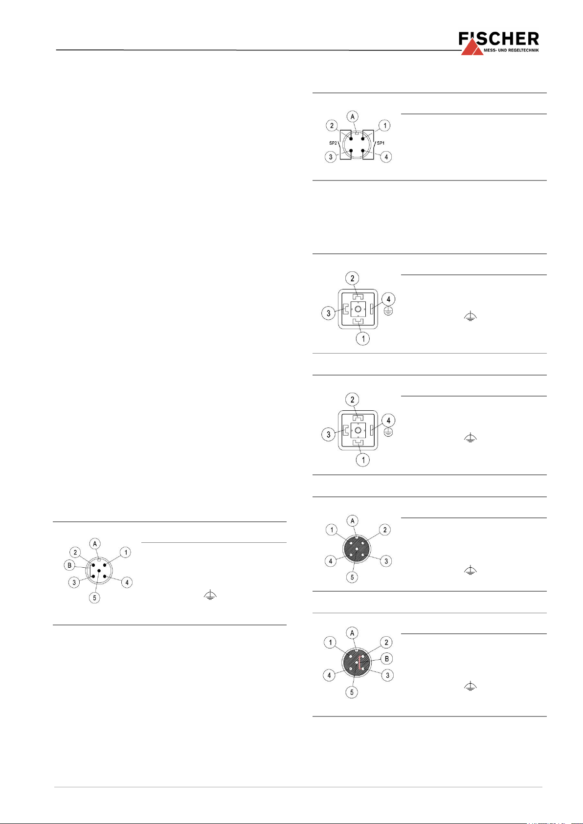
Connector 1
Pin
Signal name
Cable colour
1
+Ub brown
2
- Out white
3
- Ub blue
4
+ Out
black
5
FE green/yellow
A
Coding
B
Internal bridge Pin 2/3
Connector 2
Pin
Signal name
Cable colour
1
SP1 brown
2
SP2 white
3
SP2 blue
4
SP1 black
A Coding
Connector 3
Pin
Signal name
Cable colour
1
+ UT
+ SigT
brown
2
- UT
- SigT
blue
3
n.c. black
4
FE green/yellow
Connector 3
Pin
Signal name
Cable colour
1 + SigT
brown
2
- UT
- SigT
blue
3
+ UT black
4
FE green/yellow
Connector 3
Pin
Signal name
Cable colour
1
+ UT
+ SigT
brown
2
n.c. white
3
n.c. blue 4 - UT
- SigT
black
5
FE green/yellow
A
Coding
Connector 3
Pin
Signal name
Cable colour
1
+ UT brown
2 - SigT
white
3
- UT blue
4 + SigT
black
5
FE green/yellow
A
Coding
B
Internal bridge Pin 2/3
If the device is intended for outdoor use, we recommend permanently protecting the membrane
keypad against UV radiation and using a suitable
enclosure or at least the erection of a sufficiently
dimensioned canopy as a protection measure
against constant rain or snow.
4.1 Process connection
Please note the installation instructions and safety
information relating to the external transmitter.
4.2 Electrical connections
• By authorized and qualified specialized person-
nel only.
• When connecting the device, the relevant na-
tional and international electro-technical rules
must be observed.
• Disconnect the system from the mains, before
electrically connecting the device.
• Switch the consumer-adapted fuses.
• The following signals apply to the signals:
4.2.2 Connection of the switching outputs
4.2.3 Connection of the external transmitter
The external transmitter is connected with a 2 or 3line connection depending on the model.
2L connection standardised plug
4.2.1 Supply and output signal connection
Pin 2 and Pin 4 on units without an output signal
have no function (n.c.).
3L connection standardised plug
2L connection M12 Built-in socket
3L connection M12 Built-in socket
3 | 16 Page
Page 4

1
LC display with back lighting
2
Measurement display 4…6 digits
3
Status display of the switch points
4
Unit 5 Bar chart display
6
Keyboard
1
1
Menu downwards, reduce value
2
Call up menu, save value
3
Menu upwards, increase value
5 Commissioning
All electrical supply, operating and measuring lines,
and the pressure connections must have been correctly installed before commissioning. All supply
lines are arranged so that there are no mechanical
forces acting on the device.
5.1 Configuration
During commissioning there are a number of setting
options that allow the device to be adapted to the
measuring point and measuring task. To facilitate
the input, the individual parameters are placed into
groups in so-called menu levels.
Depending on the device model1 some menu items
are not available. For instance, no switch points can
be set on a device without contacts.
All the device settings can be made
easily on the PC using the transmitter
PC interface. Here, the parameters are
directly visible and accessible. Also, it is
possible to load and save the entire configuration; it
can also be printed out for checking (see accessories).
presentation (see Parameter MB decimal place in
section 5.3.5).).
The unit is shown on the right of the display. If the
device is equipped with contacts, a closed contact
is always symbolised by an inverted text "SP1" or
"SP2".
Various colours can be selected for the back lighting. Depending on the measured value, the colour
of the back lighting can be automatically changed.
This can be used e.g. to depict good/poor differences. The back lighting can also be deactivated.
The measured value can also be shown in a bar
chart. The measured value is also shown in smaller
pictures as a number.
During the programming, the menu items and the
associated parameters are shown on the display.
The device continues to function whilst the parameters are being set; apart from one exception, the
changes come into effect instantly. The exception
here is a change of switching times - here the previously valid time must have run down.
5.2.2 Keyboard
5.2 Control Elements
5.2.1 LC display
The individual menu items and parameters can be
displayed using the buttons þ and ÿ. The respective menu item is selected or the parameters for
making changes are called up via the button û.
If a parameter can be changed, the display flashes.
The change is made via the buttons þ and ÿ. The
value is saved with the button û.
To leave a menu level or the entire menu, select
"Quit" and press û.
In normal mode, the current measured value is
shown on a 4-digit LC display. To show very large
values, it is possible to switch to a 5 or 6-digit
with regard to the transmitter signal, voltage output, current
output, etc.
4 | 16 Page
Example: Setting the switch points
In normal mode, press the button û to enter the
menu. Menu Level Switch points appears in the
display; to change the switch points press the û
button again and the parameter Switch point 1 on
is shown.
The device jumps to the input:
Page 5

SP1 On
SP1 Off
SP1 Delay
SP1 Function
SP2 On
SP2 Off
SP2 Delay
SP2 Function
• The parameter is stated in the first line.
• The value that is to be changed is shown in the
second line, the display flashes.
• The input limits are displayed in the 3rd line (if
there is one).
The required value is set with the buttons þ and ÿ
and then confirmed with û.
5.3 Menu
Description Parameter name
Menu Level Switch points
Switch point 1:
Switch point 1 On ..................... ............ SP1 On
Switch point 1 Off ..................... ............ SP1 Off
Switch point 1 Delay ................. ............ SP1 Delay
Switch point 1 Function ............ ............ SP1 Function
Switch point 2:
Switch point 2 On ..................... ............ SP2 On
Switch point 2 Off ..................... ............ SP2 Off
Switch point 2 Delay ................. ............ SP2 Delay
Switch point 2 Function ............ ............ SP2 Function
Menu Level Input
Damping ................................... ............ Damping
Offset correction ....................... ............ Offset correction
Zero-point window .................... ............ Zero-point window
Menu Level Measuring
Measuring range start .............. ............ Meas. range Start
Measuring range end ............... ............ Meas. range. End
Measuring range unit ................ ............ Unit
Measuring range limit ............... ............ Limit
Menu Level Output
min. output .............................. ............ min. Output
max. output .............................. ............ max. Output
Error signal ............................... ............ Error signal
Menu Level Function
The menu will change depending on the entered value, linear,
square rooted or table:
(a) Value = linear:
Function: ............................ ............ linear
(b) Value = square rooted
Function: ........................... ............ Square rooted
Measuring range decimal places ..... Decimal places MB
Start of measuring range .... ............ MB-start
End of measuring range ..... ............ MB-end
Measuring range unit ......... ............ Unit MB
(c) Value= Table
Function: ........................... ............ Table
Measuring range decimal places ..... Decimal places MB
Start of measuring range .... ............ MB-start
End of measuring range ..... ............ MB-end
Measuring range unit ......... ............ Unit MB
Number of pair(s) ............... ............ Number of pairs
Depending on the input followed by :
Pair 1 ........................... ............ Value pair 1
Pair 2 ........................... ............ Value pair 2
Pair 3 ........................... ............ Value pair 3
•
•
Pair n ........................... ............ Value pair n
Menu Level Display
Colour ....................................... ........... Colour
(a) The menu changes for the value Auto1:
Red-green switchover ......... ........... Red-green switcho.
Green-red switchover ......... ........... Green-red switcho.
Hysteresis........................... ........... Hysteresis
Delay ........................... ........... Delay
Colour ........................... ........... Colour
(a) The menu changes for the value Auto2:
Red-yellow switchover ........ ........... Red-yellow switcho.
Yellow-green switchover ..... ........... Yellow-green switcho.
Green-yellow switchover ..... ........... Green-yellow switcho.
Yellow-red switchover ......... ........... Yellow-red switcho.
Hysteresis........................... ........... Hysteresis
Delay ........................... ........... Delay
Colour ........................... ........... Colour
Lighting time ............................. ........... Lighting
Contrast .................................... ........... Contrast
Bar chart ................................... ........... Bar chart
Menu Level System
Language switchover ................ ........... Language
Device information .................... ........... Software Info
Device information .................... ........... Config Info
Operating time/switch cycles ..... ........... Statistics
Access control .......................... ........... Password
Data backup ............................. ........... Load config.
Data backup ............................. ........... Save config.
5.3.1 Menu Level Switch points
The two switching outputs are configured by four
parameters respectively.
For the switch point 1 these are
Accordingly for switch point 2:
SP1 On defines the activation point, SP1 Off the
deactivation point of switch output 1. The values are
shown in the valid unit and set accordingly. The
values are shown in the valid unit and set accordingly.
Together, the two parameters determine the switch
function of switch output 1:
If SP1 Off < SP1 ON, the output switches on, if the
measured value exceeds SP1 ON. It is only
switched off again if the measured value SP1 Off is
undercut (hysteresis function).
If SP1 On = SP1 Off, the output switches on if the
measured value exceeds SP1 On and off if the
measured value undercuts SP1 Off.
If SP1 Off > SP1 ON, the output switches on, if SP1
On < Measured value < SP1 Off applies (window
function).
5 | 16 Page
Page 6

Damping
Offset correction
Zero-point window
Measuring range Start
Measuring range End
Unit
Limits
x
2x
2x x Pressure
Zero-point window
Both parameters can be set independently over the
entire range.
SP1 Delay allows the reaction of the switch output
1 to be delayed by between 0 and 1800 s. This value applies equally for switching on and off.
SP1 Function changes the function of the switch
output. It is possible here to define whether the contact should work as an open contact (NO) or a
break contact (NC).
5.3.2 Menu Level Input
If there are unsteady pressure readings during operation, you can use the parameters Damping and
Zero-point window to stabilise the reading (and
the output signal).
The effect of parameter Damping (on the reading,
output signal and switching points, if available, but
not on the measuring cell!) corresponds to that of a
capillary throttle. You can set the response time to
pressure jumps in the range 0.0 to 100 s. But with
maximum damping, it will take more than 2 minutes
for the reading to also reach zero after a pressure
jump from nominal pressure (100 %) to zero!
In many cases, unsteady readings are not a problem during normal operating mode, but this is not
true for the idle state, i.e. if a measured value of zero pressure is expected.
The parameter Zero-point window is designed to
solve this. Its value defines a range around zero at
which the measured value is set to zero (see fig.).
The display only stops showing zero when the
pressure leaves the set window. When twice the
window value is reached, the measuring pressure
and the display correspond again. This avoids
jumps in the display.
fore the offset correction, the zero-point window
should be set to zero.
Select the Offset correction parameter and correct
the reading using the buttons þ and ÿ until zero is
shown.
When setting the offset, the current measured value
is displayed. The zero-point window is not active
during the offset setting.
5.3.3 Menu Level Measuring
The transmitter output signal primarily depends on
the sensed pressure. However, you have the option
of adjusting the output signal to a large extent to
suit your requirements.
Note: However the basic measuring
range (indicated on the type label) and
the type of output signal (voltage / current) are not variable.
The parameters Start of measuring range and
End of measuring range initially define the two
pressures between which the output signal will
change at all. Both values are adjustable across the
entire basic measuring range. The set values also
refer to the pressure (in the respective unit). However, the signal values (current / voltage) for Start
of measuring range and End of measuring range
are fixed.
If Start of measuring range is smaller than End of
measuring range, this is called an increasing
characteristic curve; the output signal increases due
to the increasing pressure.
If End of measuring range is smaller than Start of
measuring range, this is a decreasing characteristic curve and the output signal decreases due to
decreasing pressure.
It makes sense to set the Offset (zero-point displacement) if, without pressure (remove measuring
line), the display shows a value that is not zero. Be-
6 | 16 Page
The difference between the values Start of meas-
uring range and End of measuring range must be
at least 25 % of the basic measuring range.
You can select a unit other than the unit of the basic
measuring range with the parameter Unit. The user
should remember however that not every unit is
suitable. The conversion is automatic.
The parameter Limit allows the display to be limited
to the range between Start of measuring range
and End of measuring range.
This makes sense when content is measured to
avoid "negative contents". If Limit is set to "no",
those measured values that are greater or smaller
than the end values are shown.
Page 7

min. output
max. output
error signal
Decimal places MB
MB-start
MB-end
Unit MB
Number of pairs
Value pair 1
Value pair 2
Value pair 3
...
Value pair 30
Value pair 1
+0.0 ... +100.0 mbar
Limits
5.3.4 Menu Level Output
The parameters min. output, max. output and error signal define the limits of the output signal that
may not be undercut or exceeded regardless of the
pressure. The limit values take priority over the
range defined by the Start of measuring range
and End of measuring range!
These parameters primarily serve to prevent error
messages in downstream systems caused by brief
overstepping of measuring ranges.
The parameter Min. output is usually only used for
devices with an output signal 4…20 mA because
frequently values of below 3.8 mA are evaluated as
error signals. The Max. output value can be used
for the voltage and current to limit the maximum
value.
The value defined via the parameter Error signal is
issued if the device detects an internal error and
can no longer work correctly. It should be noted
here that not all potential errors and faults can be
detected by the device itself.
5.3.5 Menu Level Function
TABLE: This function allows the input in the display
and output to be freely adjusted via a table which
has up to 30 support points. Pairs of values comprising the measured value and display value are
issued for the support points.
Caution: When switching from TABLE
to another function, the table is initialised again and the existing values are
lost.
The display range is defined with the parameters
Measuring range decimal points, Start of measuring range and End of measuring range. The
user can select the configuration freely.
Using the parameter decimal place MB, it is possi-
ble to select between a 5 or 6-digit presentation.
The resolution is not increased. Only an extra zero
(in the case of 6 digits, two zeros) are added.
This serves the correct display of larger values. The
measuring range must be positive for the 6 digit
presentation.
The Unit MB gives the user the option of using a
completely independent unit. Letters, numbers or
special characters can be used. The unit can be
max. 4 characters long.
If the function TABLE is selected, then it is also
necessary to state the Number of pairs. It is defined here how many pairs of values (support points)
are used in the table. At least 3, maximum 30 support points are allowed.
The reading and the output signal can be modified
in the Function menu to meet the special requirements.
There are the following functions:
LINEAR: Linear implementation of the input on the
display and the output. The range defined in the
menu "Measuring" serves as the measuring range.
If the function LINEAR is active, the other menu
items are cancelled.
SQUARE ROOTED: Here, the input signal is
square rooted before being sent to the display and
the output. This is necessary e.g. for flow measurements with differential pressure. A free unit can
be defined for the display. To do this, the start and
end of the display range and the number of decimal
points are defined. It is also possible to define the
unit with 4 characters.
Caution: If the number of value pairs is
changed, the table is initialised again
and the existing values are deleted.
The individual value pairs can be seen and
changed with Value pair 1 to (maximum) Value
pair 30.
+0.0 mbar +0.0 %
A value pair comprises a measured value (left side)
and a display value (right side). The measured value must lie within the measuring range and the display value must lie within the defined "free unit".
The respective limits are shown during input. The
table must contain increasing values.
7 | 16 Page
Page 8

Colour
Lighting
Contrast
Bar chart
Red-green switcho.
Green-red switcho.
Hysteresis
Delay
Colour
Lighting
Contrast
Bar chart
Red-yellow switcho.
Yellow-green
switcho.
Green-yellow
switcho.
Yellow-red switcho.
Hysteresis
Delay
Colour
Lighting
Contrast
Bar chart
Parameter name
Description
A
MB-start
Measuring range start
F1
Red-green switcho.
Colour-change red to green
F2
Green-red switcho.
Colour-change green to red
E
MB-end
Measuring range end
Parameter name
Description
A
MB-start
Measuring range start
F1
Red-yellow switcho.
Colour-change red to yellow
F2
Yellow-green
switcho.
Colour-change yellow to green
F3
Green-yellow
switcho.
Colour-change green to yellow
F4
Yellow-red switcho.
Colour-change yellow to red
E
MB-end
Measuring range end
Basic measuring range
Basic measuring range
Basic measuring range
5.3.6 Menu Level Display
Menu change for colour = Auto1:
Menu change for colour = Auto2:
The parameters for influencing the display are
summarised in this menu.
The most important parameter is Colour. A fixed
background colour (red, green, yellow, blue, pink,
and turquoise, white) can be selected here. There
are also two auto-functions with colour switching
available.
Auto-function red-yellow-green (Auto2)
Note: If a range cannot be used, the as-
sociated switch thresholds can be set to
the same value.
Example:
The parameter Colour is set to Auto2. Only the
green, yellow and red ranges are required here. To
fade out the lower ranges red and yellow, the switch
thresholds "red-yellow switching" and "yellow-green
switching" are set to the start of the measuring
range.
Auto1: red-green,
Auto2: red-yellow-green.
Alternatively, the background illumination can be
permanently deactivated.
In the mode with the automatic colour switchover, it
is possible to enter the required switch thresholds
"red-yellow switchover", "yellow-green switchover",
green-yellow switchover, "yellow-red switchover" or
"red-green switchover" and "green-red switchover".
The switching thresholds can be moved within the
measuring range. The series of switch points cannot be altered.
Auto-function red-green (Auto1)
8 | 16 Page
The parameter Hysteresis can be used to prevent
fast and unwanted colour changes. The hysteresis
is set in the range 0.1... 10%.
Note: In the case of large hysteresis
values, steps must be taken to ensure
that the ranges of the individual colours
do not overlap. Otherwise it is possible
that the colour change may not function in the desired way.
The parameter Delay offers a further option to prevent unwanted colour changes.
Page 9

Language
Software info
Config info
Statistics
Password
Load config.
Config. Save
The colour change here can be delayed between
0…1800 s.
If permanent lighting is not required, the parameter
Lighting can be used to define when the lighting
should be switched off after the last time a button is
pressed. In addition to permanent lighting, automatic shut-down after 10…600 s is also possible. The
set time is only valid if the parameter Background
colour is not set to "off".
Amongst other things, the legibility of the display
depends on the temperature and the reading angle.
To ensure optimised legibility, this can be adjusted
using the parameter Contrast. When the contrast is
changed, it is possible that the display appears
empty or almost completely black. In this case, the
contrast must be turned up or down.
The parameter Bar chart is used to switch the display as follows. Either the measured value is displayed with large digits or the display uses small
digits and an additional bar chart to show the
measured value more quickly.
5.3.7 Menu Level System
Caution: The user is not able to delete
a forgotten password!
The user can load a saved configuration
via the menu item Load config. This means that a
functional set of parameters can be loaded after trying out various settings.
Note: If the user has not yet saved a
configuration, the default values (status
on delivery) are loaded. In this case, any
measuring range spreads or switch
points are reset and the device needs to be newly
configured.
The menu item Save config. serves to save the existing parameters in a protected memory area. This
is helpful if the settings of a functional device needs
to be optimised. Save config. and Load config.
can be used to quickly restore the initial status
again.
6 Maintenance
The instrument is maintenance-free.
The user menu can be switched to German, English,
French, Spanish or Italian using the parameter
Language.
The menu items Software - Info and Config - Info
provide information about the device. This information helps to answer questions about the device
quickly.
The device type, controller ID and the firmware version is shown in the software info.
The basic measuring range, the defined output signal and existing contacts are stated in the Config Info.
The Statistics provide information about the operating time and the relay switching cycles from the
time of delivery. The operating time is shown in
days (d) and hours (h)
In the menu item Password the menu can be protected with a password to prevent unauthorised
changes. The password is a figure from 1 to 999.
The input 0 means that no password is active.
The password needs to be set if the user presses
the button in normal mode to enter the menu. If a
wrong password is entered, the system automatically jumps back to normal mode again. If no password is active, the display immediately jumps to the
menu.
We recommend the following regular inspection to
guarantee reliable operation and a long service life:
• Check the reading.
• Check the function in combination with down-
stream components.
• Check the leak-tightness of the pressure con-
nection lines.
• Check the electrical connections.
The exact test cycles need to be adapted to the op-
erating and environmental conditions. If various instrument components interact, the operating instructions of all the other instruments also need to
be observed.
7 Transportation
The measuring device must be protected against
impacts. It may only be transported in packaging
specifically intended for transport.
8 Service
All defective or faulty devices should be
sent directly to our repair department.
Please coordinate all shipments with
our sales department.
Process media residues in and on dismantled devices can be a hazard to people, animals and the
environment. Take adequate preventive measures.
If required, the devices must be cleaned thoroughly.
9 | 16 Page
Page 10

9 Accessories
• Set of cables with M12 connectors (please en-
quire)
10 Waste Disposal
For the sake of the environment ....
Please help to protect our environment
and dispose of or recycle used instruments as stipulated by the applicable
regulations.
10 | 16 Page
Page 11

Input signal
0…20 mA
4...20 mA
0...10 V
The stated values refer to the analysis unit and do
not take into account the property of the connected
filling level transmitter!
Max. characteristic curve deviation
%FS
0.1
Typ. characteristic curve deviation
%FS
< 0.05
Tk span max.°°
%FS/10K
< 0.1
Tk span typ.°°
%FS/10K
< 0.025
Tk zero point max.°°
%FS/10K
< 0.1
Tk zero point typ.°°
%FS/10K
< 0.025
General points
Admissible ambient temperature
-10 ... 70°C
Admissible media temperature
see data sheet of the connected sensor
Admissible storage temperature
-20 ... 70°C Enclosure protection class
IP 65 acc. to DIN EN 60529
Electrical data
Rated Voltage
24 VDC / VAC
Allowed operating voltage Ub
12...32 VDC / VAC
Electrical connection type
Three-conductor
Output signal
0...20 mA, 4...20 mA, 0...10 VDC
Admissible apparent ohmic
resistance
for current output RL (Ub - 4 V) / 0.02 A (Ub 26V), otherwise RL 1100
for voltage output RL 2 K (Ub 15 V), RL 10 K (Ub = 12 …15V)
Switch contacts
2 potential-free relay contacts
Progr. switching function
Open contact (NO) / break
contact (NC)
Switching voltage
max. 32 V DC/AC
Max. switching current
2A
Max. switching output
64 W/VA
Power consumption
approx. 2 W / VA (without external sensors)
Advertisement
LCD graphic display
Ports
electr. connection
2 x fitted connectors M12 coding
Connector 1 for supply and analogue output signal (5-pin)
Connector 2 for switch contacts (4-pin)
External pressure transmitter
Connector 3
1m cable with standardised plug DIN EN 175 301-803-A (4-pin) or
Built-in socket M12 Code A (5-pin)
Materials
Housing
Polyamide PA 6.6
Media-contacting material
see data sheet of the connected sensor
Montage
Assembly of the mounting rails
Panel mounting set
Wall mounting
11 Technical Data
°: Characteristic curve deviation (non-linearity and hysteresis) at 25°C, and rated voltage, in reference to basic measuring range (linear
characteristic curve, not spread)
°°: with reference to the basic measuring range (linear characteristic curve, not spread),
11 | 16 Page
Page 12

11.1 Programming
Settings
Attenuation
Switch output 1 / 2
Measuring range unit
Zero-point stabilising
Output signal
Zero point correction
Implementation of characteristic curve
Password
(all dimensions in mm unless otherwise specified)
Wall mounting plate
(optional)
Rear view
without wall mounting plate
(standard)
Connector 1
Connector 2
Boreholes for tapping
screws diam. 3.5 mm
M12 plug connection
Standardised
plug DIN EN 175 301-803-A
M12 Built-in socket
Programmed via the membrane keyboard with menu navigation; locked with a password.
0.0 ... 0.0 … 100.0 s (jump response time 10 / 90 %) for signal output; separately also for display
Switch-off point, switch-on point, response time (0 ... 100 s); function (NO contact /NC contact)
mbar / Pa / "free unit", starting value, end value and decimal point for "free unit"
0 ... 1/3 of the basic measuring range (1)
User-definable within the basic measuring range
± 1/3 of the basic measuring range (3)
linear, square rooted, table with 3...30 support points
001 ... 999 (000 = no password protection)
Comments:
(1) Measuring values (around zero) were set to zero. (e.g. to suppress seepage).
(2): Maximum effective spread 4:1. Only the output signal is influenced.
This in turn enables a decreasing characteristic curve, if the start of the measuring range > end of the measuring range.
(3): Zero point correction for compensation of various installation positions.
(2)
12 Dimensional drawings
12 | 16 Page
Page 13

Wall thickness 3-5 mm
12.1 Assembly of the mounting rails
DIN attachment element for assembly of the mounting rails in compliance with EN 60715
12.2 Installation of front panel
13 | 16 Page
Page 14

Pressure analysis unit with colour change LCD
EA14
M 0 K W M
Version
Pressure ...................................................................... >
M
Measuring range
0…. 0.6 bar ..................................................................... >
0 1
0…. 1 bar ..................................................................... >
0 2
0…. 1.6 bar ..................................................................... >
0 3
0…. 2.5 bar ..................................................................... >
0 4
0…. 4 bar ..................................................................... >
0 5
0…. 6 bar ..................................................................... >
0 6
0…. 10 bar ..................................................................... >
0 7
0…. 16 bar ..................................................................... >
0 8
0…. 25 bar ..................................................................... >
0 9
0…. 40 bar ..................................................................... >
1 0
0…. 60 bar ..................................................................... >
1 1
0…. 100 bar ..................................................................... >
1 2
0…. 160 bar ..................................................................... >
1 3
0…. 250 bar ..................................................................... >
1 4
0…. 400 bar ..................................................................... >
1 5
-1…. 0 bar ..................................................................... >
3 1
-1…. 0.6 bar ..................................................................... >
3 2
-1…. 1.5 bar ..................................................................... >
3 3
-1…. 3 bar ..................................................................... >
3 4
-1…. 5 bar ..................................................................... >
3 5
-1…. 9 bar ..................................................................... >
3 6
-1…. 15 bar ..................................................................... >
3 7
0…. -1 bar ..................................................................... >
3 9
Electrical connection pressure transmitter
M12 plug connection ............................................................................ >
M
Plug connector DIN EN 175301-803 A, 1m cable ................................. >
H
Electrical input signal
0 - 20 mA 3-LINE. ................................................................................. >
A
4 - 20 mA 2-LINE .................................................................................. >
B
0 - 10 V DC 3-LINE. ................................................................................. >
C
Electrical output signal
without analogue electrical output signal ........................................................... >
0
0 - 20 mA 3-LINE .......................................................................................... >
A
0 - 10 V DC 3-LINE. ....................................................................................... >
C
4 - 20 mA 3-LINE .......................................................................................... >
P
Operating voltage
24 V DC/AC (12 - 32 V DC/AC) ....................................................................................................... >
K
Measuring unit
Selectable pressure units ...................................................................................................................... >
W
Measured value display / contact elements
4-digit colour change LCD - 2 relay contacts ........................................................................ >
C
4-digit colour change LCD - 2 semiconductor contacts ........................................................ >
D
Electrical connection
M12 plug connection ................................................................................................................. >
M
Assembly option
Standard (attachment boreholes on rear side) ................................................................................. >
0
Assembly of the mounting rails ........................................................................................................ >
S
Panel mounting set .......................................................................................................................... >
T
Wall mounting .................................................................................................................................. >
W
13 Order Codes
14 | 16 Page
Page 15

14 Manufacturer's Declarations and Certificates
15 | 16 Page
Page 16

Technische Änderungen vorbehalten • Subject to change without notice • Changements techniques sous réserve
Fischer Mess- und Regeltechnik GmbH • Bielefelder Str. 37a • D-32107 Bad Salzuflen • Tel. +49 5222 9740 • Fax +49 5222 7170 •
eMail: info@fischermesstechnik.de • www.fischermesstechnik.de
 Loading...