

Page 1
Operating manual
EA14D
Differential pressure evaluation unit
with colour change LCD
09005114 • BA_EN_EA14D • Rev. ST4-A • 06/18
*09005114*
Page 2

| Masthead FISCHER Mess- und Regeltechnik GmbH
Masthead
Manufacturer:
Technical editorial team:
FISCHER Mess- und Regeltechnik GmbH
Bielefelderstr. 37a
D-32107 Bad Salzuflen
Telephone: +49 5222 974 0
Telefax: +49 5222 7170
eMail: info@fischermesstechnik.de
web: www.fischermesstechnik.de
Documentation representative: T. Malischewski
Technical editor: R. Kleemann
All rights, also those to the translation, reserved. No part of this document may
be reproduced or processed, duplicated or distributed using electronic systems
or any other form (print, photocopy, microfilm or another process) without the
written consent of the company FISCHER Mess- und Regeltechnik GmbH, Bad
Salzuflen.
Reproduction for internal use is expressly allowed.
Brand names and procedures are used for information purposes only and do
not take the respective patent situation into account. Great care was taken
when compiling the texts and illustrations; Nevertheless, errors cannot be ruled
out. The company FISCHER Mess- und Regeltechnik GmbH will not accept any
legal responsibility or liability for this.
Subject to technical amendments.
© FISCHER Mess- und Regeltechnik 2018
Version history
Rev. ST4-A 06/18 Version 1 (first edition)
2 / 36 BA_EN_EA14D
Page 3

FISCHER Mess- und Regeltechnik GmbH Table of contents
Table of contents
1 Safety instructions .........................................................................................................................................4
1.1 General .....................................................................................................................................................4
1.2 Personnel Qualification.............................................................................................................................4
1.3 Risks due to Non-Observance of Safety Instructions ...............................................................................4
1.4 Safety Instructions for the Operating Company and the Operator............................................................4
1.5 Unauthorised Modification ........................................................................................................................4
1.6 Inadmissible Modes of Operation .............................................................................................................4
1.7 Safe working practices for maintenance and installation work .................................................................5
1.8 Pictogram explanation ..............................................................................................................................5
2 Product and functional description ..............................................................................................................6
2.1 Delivery scope ..........................................................................................................................................6
2.2 Intended use .............................................................................................................................................6
2.3 Function diagram ......................................................................................................................................6
2.4 Design and mode of operation..................................................................................................................6
2.5 Equipment versions ..................................................................................................................................7
3 Assembly.........................................................................................................................................................9
3.1 General .....................................................................................................................................................9
3.2 Process connection (external pressure transmitter) .................................................................................9
3.3 Electrical connection (auxiliary energy, output signals) ..........................................................................10
4 Start-up..........................................................................................................................................................12
4.1 General ...................................................................................................................................................12
4.2 Configuration ..........................................................................................................................................12
4.3 LC display ...............................................................................................................................................12
4.4 Keyboard ................................................................................................................................................13
4.5 Menu levels.............................................................................................................................................14
5 Servicing .......................................................................................................................................................27
5.1 Maintenance ...........................................................................................................................................27
5.2 Transport ................................................................................................................................................27
5.3 Service....................................................................................................................................................27
5.4 Disposal ..................................................................................................................................................27
6 Technical data...............................................................................................................................................28
6.1 Generalities.............................................................................................................................................28
6.2 Input variables ........................................................................................................................................28
6.3 Output sizes............................................................................................................................................28
6.4 Measurement accuracy ..........................................................................................................................29
6.5 Auxiliary energy .....................................................................................................................................29
6.6 Operating conditions...............................................................................................................................29
6.7 Display and operating interface ..............................................................................................................29
6.8 Construction design ................................................................................................................................30
7 Order codes ..................................................................................................................................................34
7.1 Accessories ............................................................................................................................................35
8 EU Declaration of Conformity .....................................................................................................................36
BA_EN_EA14D 3 / 36
Page 4

1 | Safety instructions FISCHER Mess- und Regeltechnik GmbH
1 Safety instructions
1.1 General
This operating manual is an integral part of the product and therefore needs to
be kept close to the instrument in a place that is accessible at all times to the responsible personnel.
The following sections, in particular instructions about the assembly, commissioning and maintenance, contain important information, non-observance of
which could pose a threat to humans, animals, the environment and property.
The instrument described in these operating instructions is designed and manufactured in line with the state of the art and good engineering practice.
1.2 Personnel Qualification
The instrument may only be installed and commissioned by specialized personnel familiar with the installation, commissioning and operation of this product.
Specialized personnel are persons who can assess the work they have been
assigned and recognize potential dangers by virtue of their specialized training,
their skills and experience and their knowledge of the pertinent standards.
1.3 Risks due to Non-Observance of Safety Instructions
Non-observance of these safety instructions, the intended use of the device or
the limit values given in the technical specifications can be hazardous or cause
harm to persons, the environment or the plant itself.
The supplier of the equipment will not be liable for damage claims if this should
happen.
1.4 Safety Instructions for the Operating Company and the Operator
The safety instructions governing correct operation of theinstrument must be
observed. The operating company must make them available to the installation,
maintenance, inspection and operating personnel.
Dangers arising from electrical components, energy discharged by the medium,
escaping medium and incorrect installation of the device must be eliminated.
See the information in the applicable national and international regulations.
Please observe the information about certification and approvals in the Technical Data section.
1.5 Unauthorised Modification
Modifications of or other technical alterations to the instrument by the customer
are not permitted. This also applies to replacement parts. Only the manufacturer
is authorised to make any modifications or changes.
1.6 Inadmissible Modes of Operation
The operational safety of this instrument can only be guaranteed if it is used as
intended. The instrument model must be suitable for the medium used in the
system. The limit values given in the technical data may not be exceeded.
The manufacturer is not liable for damage resulting from improper or incorrect
use.
4 / 36 BA_EN_EA14D
Page 5
FISCHER Mess- und Regeltechnik GmbH Safety instructions | 1
1.7 Safe working practices for maintenance and installation work
The safety instructions given in this operating manual, any nationally applicable
regulations on accident prevention and any of the operating company's internal
work, operating and safety guidelines must be observed.
The operating company is responsible for ensuring that all required maintenance, inspection and installation work is carried out by qualified specialized personnel.
1.8 Pictogram explanation
DANGER
Type and source of danger
This indicates a direct dangerous situation that could lead to death or serious
injury (highest danger level).
a) Avoid danger by observing the valid safety regulations.
WARNING
Type and source of danger
This indicates a potentially dangerous situation that could lead to death or serious injury (medium danger level).
a) Avoid danger by observing the valid safety regulations.
CAUTION
Type and source of danger
This indicates a potentially dangerous situation that could lead to slight or serious injury, damage or environmental pollution (low danger level).
a) Avoid danger by observing the valid safety regulations.
NOTICE
Note / advice
This indicates useful information of advice for efficient and smooth operation.
BA_EN_EA14D 5 / 36
Page 6
2 | Product and functional description FISCHER Mess- und Regeltechnik GmbH
SP1
SP2
Sig 1
Sig 2
1,234
A
D
A
D
µC
þ û ÿ
D
A
D
A
+
1
2
1
3
4
Channel 1
Channel 2
2 Product and functional description
2.1 Delivery scope
• 1 x differential pressure evaluation unit EA14D
• 2 x pressure transmitter incl. connection cable
• Operating Manual
– Analysis unit
– Pressure Transmitter
2.2 Intended use
The device can be used as a display and switching unit in combination with two
external service sensors (0/4…20 mA and/or 0…10 V). The medium compatibility depends on the technical data of the sensors used.
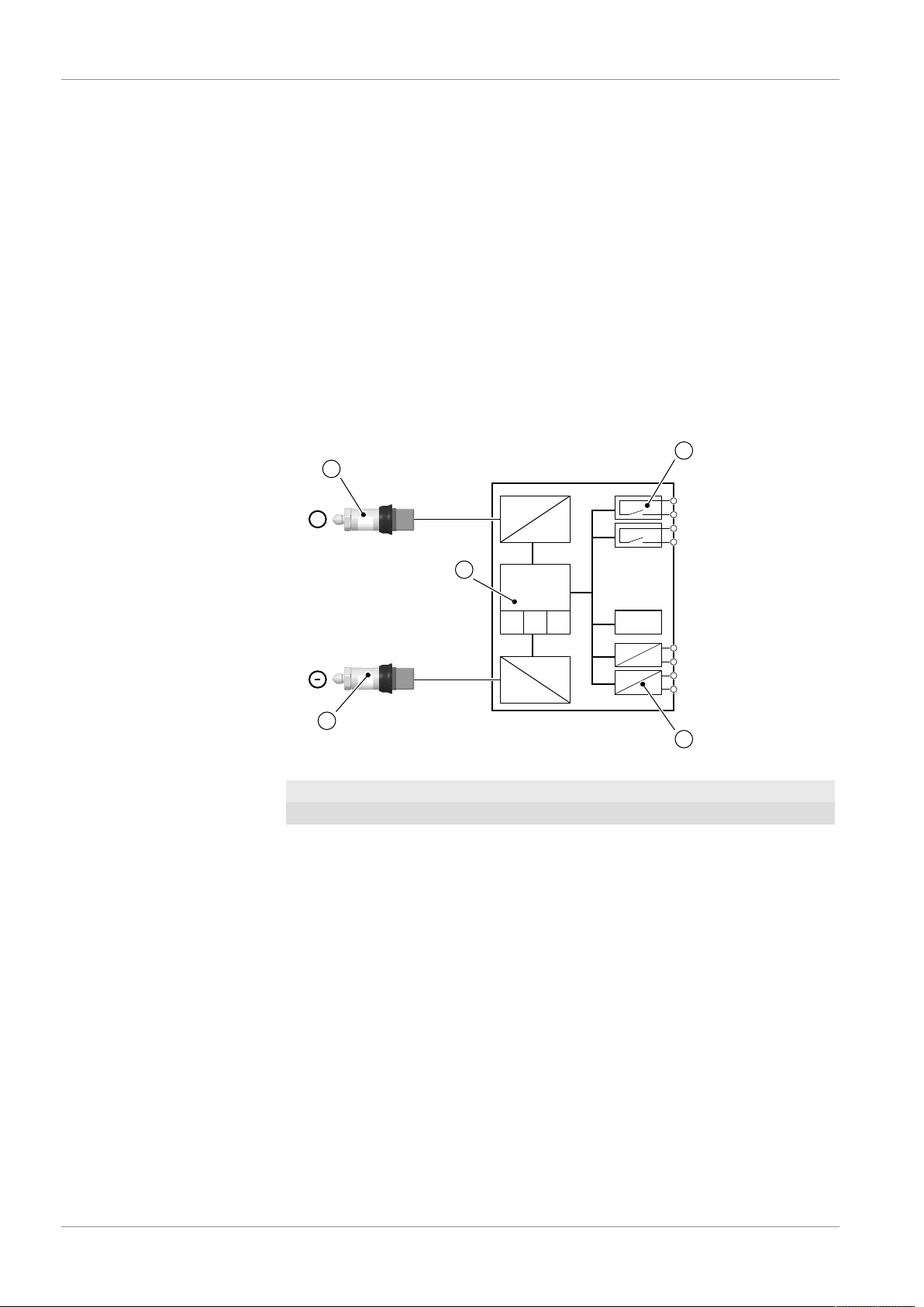
2.3 Function diagram
Fig.1: Function diagram
1 External pressure sensor 2 Switch output
3 Optional analogue output 4 Micro-controller
2.4 Design and mode of operation
The device is based on an electronic evaluation circuit that analyses the measuring signals of two external pressure transmitters. The main task is the calculation of the differential pressure that can be displayed and analysed. The signals
of the external pressure transmitters can be shown separately for review. The
evaluation unit allows two independent switch points to be set. Optionally two
additional output signals can be made available.
The external pressure transmitters are connected to the differential pressure
evaluation unit via flexible plug connection lines. Only the supplied pressure
transmitters may be connected. The nominal pressures of the external sensors
6 / 36 BA_EN_EA14D
and the basic measuring range are set ex-works and stated on the type plate.
Page 7
FISCHER Mess- und Regeltechnik GmbH Product and functional description | 2
EA14 D... H ... EA14 D... M ...
Type plate
Wiring diagram
+
+
Process connection
Supply
Switch output
Standard Wall mounting
Panel installation Assembly of the mounting rails
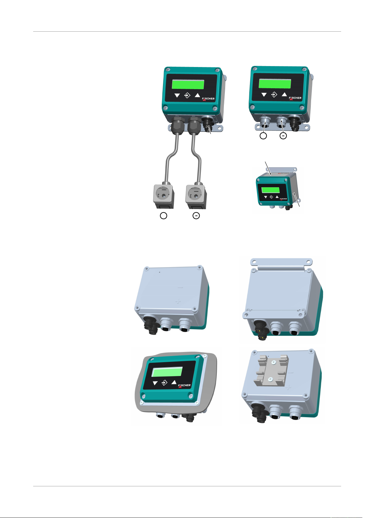
2.5 Equipment versions
Fig.2: Equipment versions
2.5.1 Assembly types
BA_EN_EA14D 7 / 36
Fig.3: Assembly types
Page 8

2 | Product and functional description FISCHER Mess- und Regeltechnik GmbH
Item no.
Basic measuring range
Input signal
Output signals
Ub
Switch contacts
Prod.-No.
24 V AC/DC
Umax. 32 V AC/DC Imax. 2 A
Pmax. 64 VA / 64 W
Δ P, P1/P2 0 ... 20 mA
0 ... 20 mA
0 ... 6 bar
EA14D006MA4KWCMW
1806856.01.086
Order code
Techn. Data
Serial number
2.5.2 Type plate
Fig.4: Type plate
8 / 36 BA_EN_EA14D
Page 9
FISCHER Mess- und Regeltechnik GmbH Assembly | 3
+
1 2
4 3
5
A
1 2
4 3
5
A
3 Assembly
3.1 General
The device is designed for installation onto flat assembly plates. For screw connection to the assembly plate, the device features four assembly bores on its
back, which can be used for Ø 3.5 mm tapping screws. Optionally, the device
can be delivered with a wall-mounting plate, a front-mounted panel set or an adapter for assembly of the support rail.
3.2 Process connection (external pressure transmitter)
• By authorized and qualified specialized personnel only.
• The pipes need to be depressurized when the pressure transmitter is being
connected.
• Appropriate steps must be taken to protect the pressure sensors from pressure surges.
• Check that the pressure transmitter is suitable for the medium being measured.
• Please observe the maximum pressure levels.
The information about the connection of the pressure lines are stated in the operating instructions for the pressure transmitters. The external connection of the
two external pressure transmitters is realised with a 2 or 3-line connection depending on the model. The supplied connection lines are manufactured accordingly.
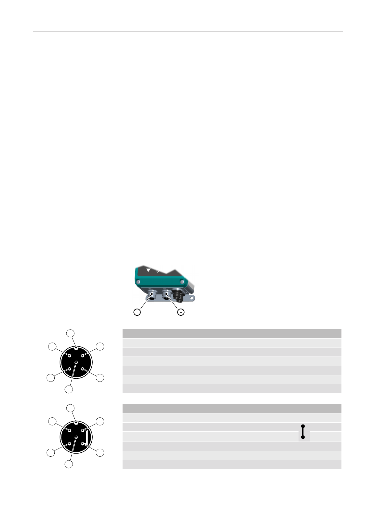
3.2.1 M12 plug connection
The plug assignment is identical for both inputs. The plug connections are
marked with (+) and (-) on the equipment.
Fig.5: Process connection
PIN Signal (2L pressure transmitter)
1 Pressure transmitter signal and supply (+) +SigT/+U
2
3 Pressure transmitter signal and supply (-) -SigT/-U
4
5 Functional earth Fe
A Coding
Tab.1: Connection for 2-wire pressure transmitter
PIN Signal (3L pressure transmitter)
1 Pressure transmitter supply (+) +U
2 Pressure transmitter signal (-) -Sig
3 Pressure transmitter supply (-) -U
4 Pressure transmitter signal (+) +Sig
5 Functional earth Fe
A Coding
Tab.2: Connection for 3-wire pressure transmitter
T
T
T
T
T
T
BA_EN_EA14D 9 / 36
Page 10

3 | Assembly FISCHER Mess- und Regeltechnik GmbH
1
3
2
Plug 2
Plug 1
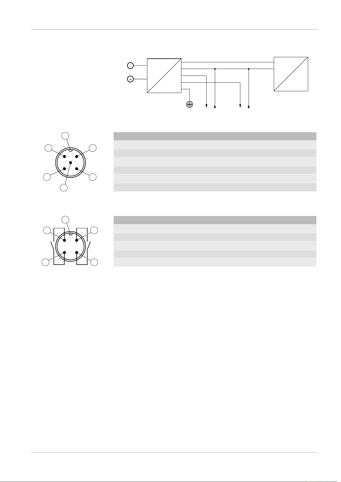
3.2.2 Plug connector DIN EN 175301-803 A
The plug assignment is identical for both inputs. The plugs are marked with (+)
and (-).
Fig.6: Process connection
PIN Signal (2L pressure transmitter)
1 Pressure transmitter signal and supply (+) +SigT/+U
2 Pressure transmitter signal and supply (-) -SigT/-U
3
Functional earth Fe
Tab.3: Connection for 2-wire pressure transmitter
PIN Signal (3L pressure transmitter)
1 Pressure transmitter signal (+) +Sig
2 Pressure transmitter supply (+) +U
3 Pressure transmitter signal and supply (-) -SigT/-U
Functional earth Fe
T
T
T
T
T
Tab.4: Connection for 3-wire pressure transmitter
3.3 Electrical connection (auxiliary energy, output signals)
• By authorized and qualified specialized personnel only.
• When connecting the unit, the national and international electro-technical
regulations must be observed.
• Disconnect the system from the mains, before electrically connecting the
device.
• Install the consumer-adapted fuses.
• Do not connect the connector if strained.
The information about the approved operating voltage and the approved load
for the analogue outputs are in the Technical Data section.
The M12 plugs are marked with (1) and (2) on the equipment.
Fig.7: Electrical connection
10 / 36 BA_EN_EA14D
Page 11
FISCHER Mess- und Regeltechnik GmbH Assembly | 3
Mains adapter
+Out2
+U
b
-U
b
Output1
EA14D
+
+Out1
24 V AC/DC
230 V AC
+ (~)
- (~)
Plug 1
1
3
2
4
Output2
5
FE
2 1
3 4
5
A
2 1
3
A
4
SP1SP2
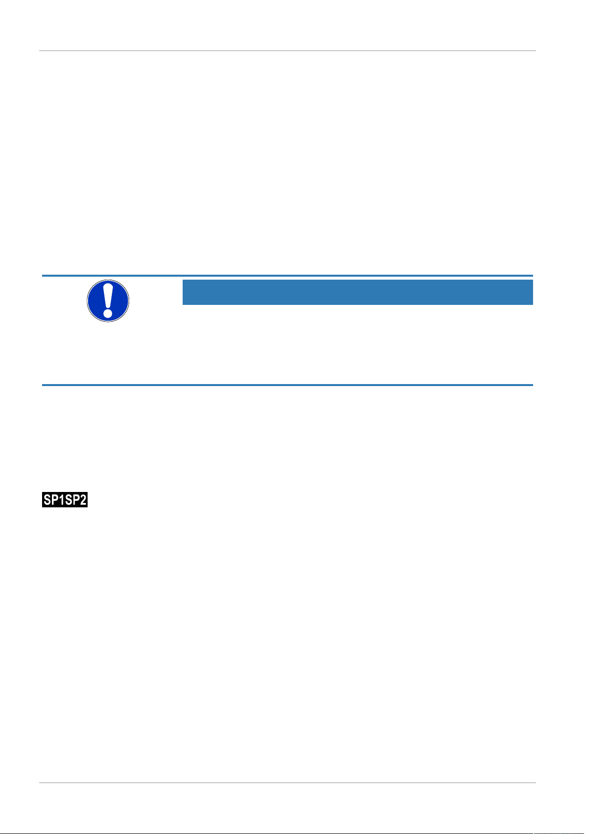
3.3.1 Plug 1: Auxiliary energy, analogue output
Fig.8: Analogue output connection
PIN Signal
1 Operating voltage (+) +U
2 Analogue output 2 (+) +Out2
3 Operating voltage (-) -U
4 Analogue output 1 (+) +Out1
5 Functional earth Fe
A Coding
Tab.5: Auxiliary energy and analogue output connection
b
b
3.3.2 Connector 2: Switch output
PIN Signal
1 Switching output 1 SP1
2 Switching output 2 SP2
3 Switching output 2 SP2
4 Switching output 1 SP1
A Coding
Tab.6: Connection of the switching outputs
BA_EN_EA14D 11 / 36
Page 12
4 | Start-up FISCHER Mess- und Regeltechnik GmbH
4 Start-up
4.1 General
All electrical supply, operating and measuring lines, and the pressure connections must have been correctly installed before commissioning. All supply lines
are arranged so that there are no mechanical forces acting on the device.
Check that the pressure connections do not leak before commissioning.
4.2 Configuration
During commissioning there are a number of setting options that allow the
device to be adapted to the measuring point and measuring task. To facilitate
the input, the individual parameters are placed into groups in so-called menu
levels.
Depending on the device model some menu items are not available. For instance, no switch points can be set on a device without contacts.
NOTICE
Parameter configuration on the PC
All the device settings can be made easily on the PC using the PC adapter. You
will need a Transmitter PC Interface and the associated PC software. For more
details, please refer to the Accessories section. The PC software makes all
parameters directly visible and accessible. Also, the entire configuration can be
loaded, saved and documented as a printout.
Fig.9: LC display 2SP
4.3 LC display
In normal mode, the current measured value of an input channel is shown on a
4-digit LC display. To show very large values, it is possible to switch to a 5 or 6digit presentation (see Parameter MB decimal place).
In the one-line presentation of the measured value, the display can be
'switched' to the respective other channel using the arrow
key is released, the originally display channel is shown again.
The unit is shown to the right of the measured value. If the device is equipped
with contacts, a closed contact is always symbolised by an inverted text "SP1"
or "SP2". One exception is the 1-channel bar chart diagram. Here, the switching
points are symbolised with simple numbers "12".
Various colours can be selected for the back lighting. Depending on the measured value, the colour of the back lighting can be automatically changed. This
can be used e.g. to depict good/poor differences. The back lighting can also be
deactivated.
The measured value can also be shown in a bar chart. The measured value is
also shown in smaller pictures as a number.
During the programming, the menu items and the associated parameters are
shown on the display. The device continues to function whilst the parameters
are being set; apart from one exception, the changes come into effect instantly.
The exception here is a change of switching times - here the previously valid
time must have run down.
. As soon as the
(a) Operating mode differential pressure:
In this operating mode, the first channel is assigned to the differential pressure
measurement. The second channel of the pressure measurement P+. According to this assignment, the measured values are shown (see Fig.). There is also
an option for displaying all values, however it is then not possible to show a bar
chart.
12 / 36 BA_EN_EA14D
Page 13

FISCHER Mess- und Regeltechnik GmbH Start-up | 4
1 input channel
2 input channels
All values
(only differential pressure)
1 4 5
23
(b) Operating mode 2-channel
In this operating mode, the first channel is assigned to the differential pressure
(P+). The second channel of the pressure measurement (P-). According to this
assignment, the measured values and the channel numbers (ch1) and (ch2) are
shown.
Fig.10: LC display
1 Measured value 2 Unit
3 Input signal assignment 4 Status display of the switch
points
5 Bar chart
4.4 Keyboard
Fig.11: Operating keys [LC display]
1 Page down menu Reduce value
2 Call up menu Save value
3 Page up menu Increase value
The individual menu items and parameters can be displayed using the buttons
and
changes are called up via the button
. The respective menu item is selected or the parameters for making
.
BA_EN_EA14D 13 / 36
Page 14

4 | Start-up FISCHER Mess- und Regeltechnik GmbH
End
menu level
Menu Level
Switch points
Menu Level
Input
Menu Level
Measuring
Menu Level
Output
Menu Level
Function
Menu Level
Display
Menu Level
System
End
menu level
Receipt
Outlet
Outlet
Menu level
Function 2
Only in the operating mode
2-channel
If a parameter can be changed, the display flashes. The change is made via the
buttons
To leave a menu level or the entire menu, select the parameter "Menu level
Quit" and press
and
. The value is saved with the button
.
.
Example: Switch-on point set switchpoint 1
In normal mode, press the button
points appears. Press the enter key
The first parameter SP 1 On is displayed. To change this parameter, press the
button
The device jumps to the input:
• The parameter is stated in the 1st line.
• The value that is to be changed is shown in the 2nd line, the display flashes.
• The input limits are displayed in the 3rd line (if there is one).
The required value is set with the buttons
.
again.
to enter the menu. The menu level Switch
again to call up the display parameter.
and
and then confirmed with
4.5 Menu levels
14 / 36 BA_EN_EA14D
Fig.12: Menu levels
Page 15

FISCHER Mess- und Regeltechnik GmbH Start-up | 4
4.5.1 Menu Level Switch points (2SP)
Parameter name Description Value range
SP1 On Switch point 1 On MBA-50% … MBE+50%
SP1 Off Switching point 1 off MBA-50% … MBE+50%
SP1 delay Switching point 1 delay 0…1800 s
SP1 Function Switching point 1 function NO, NC
Assignment SP Channel assignment Channel 1, 2 and 1+2
SP2 On Switch point 2 On MBA-50% … MBE+50%
SP2 Off Switching point 2 off MBA-50% … MBE+50%
SP2 delay Switching point 2 delay 0…1800 s
SP2 Function Switching point 2 function NO, NC
The two switching outputs are configured by four parameters respectively.
For the switch point 1 these are:
• SP1 On
• SP1 Off
• SP1 delay
• SP1 Function
Accordingly for switch point 2:
• SP2 On
• SP2 Off
• SP2 delay
• SP2 Function
The function of the individual parameters is explained for both switch points using Switch point 1 as an example.
SP1 On defines the activation point, SP1 Off the deactivation point of switching
output 1. The values are shown in the valid unit and set accordingly. The values
are shown in the valid unit and set accordingly. Both parameters can be set independently over the entire value range.
The value range ranges from MBA – 50% to MBE + 50%. MBA stands for start
of measuring range and MBE for the end of the measuring range.
Example: Measuring range = 0 … 100 %
The value range for this measuring range is -50 % … +150 %.
Function of the switch points
Together, the two parameters SP1 On and SP1 Off determine the switch function of switching output 1:
• If SP1 On > SP1 Off, the output switches on, if the measured value exceeds SP1 On. It is only switched off again if the measured value SP1 Off is
undercut (hysteresis function).
• If SP1 On = SP1 Off, the output switches on if the measured value exceeds
SP1 On and off if the measured value undercuts the same value (SP1 Off).
• If SP1 On < SP1 Off, the output switches on, if the measured value lies
within these switch points: i.e:
SP1 On < Measured value < SP1 Off (window function).
SP1 Delay allows the reaction of the switch output 1 to be delayed by between
0 and 1800 s. This parameter applies equally for switching on and off.
SP1 Function changes the function of the switching output 1. It is possible here
to define whether the contact should work as a open contact (NO) or a break
contact (NC).
BA_EN_EA14D 15 / 36
Page 16

4 | Start-up FISCHER Mess- und Regeltechnik GmbH
Assignment SP is used to define the input to which the contacts are assigned.
The following options are available:
• Channel 1
Both contacts are assigned to channel 1.
• Channel 1, channel 2
A contact is assigned to every channel.
Channel 1: SP1
Channel 2: SP2
• Channel 2
Both contacts are assigned to channel 2.
The unit and the input range are adapted accordingly when entering the switch
points.
4.5.2 Menu Level Input
Operating mode Channel 1 Channel 2
Differential pressure Differential pressure (dP) Pressure (P+)
2-channel Pressure (P+) Pressure (P-)
Channel 1:
Channel 2:
Parameter name Description Value range
Absorption Damping 0…100 s
Offset corr. Offset correction ⅓ basic measuring
range
Zero-pt. wind. Zero-point window ⅓ basic measuring
range
Parameter name Description Value range
Absorption 2 Damping 0…100 s
Offset corr. 2 Offset correction ⅓ basic measuring
range
Zero-pt. wind.2 Zero-point window ⅓ basic measuring
range
The parameters for both channels are set in the same way. The following explains the parameters for the first channel as an example for both channels.
If there are unsteady measurement readings during operation, you can use the
parameters Absorption and Zero-pt. wind. to stabilize the reading (and the
output signal).
The parameter Absorption functions like a capillary throttle. However, it only
acts on the display, output signal and switch points (if these exist) but not on the
measuring cell itself.
You can set the response time to measuring value jumps in the range 0.0 to
100 s.
NOTICE
Response time
At maximum damping, it can take over 2 minutes until after a measurement
jump from 100% to 0% is also shown as zero in the display.
In many cases, unsteady readings are not a problem during normal operating
mode, but this is not true for the idle state, i.e. if a measured value of zero is expected. The parameter Zero-pt. wind. is designed to solve this. Its value
defines a range around zero at which the measured value is set to zero (see
fig.).
16 / 36 BA_EN_EA14D
Page 17

FISCHER Mess- und Regeltechnik GmbH Start-up | 4
Measured Value
Display value
-x-2x x 2x
Zero-point window
The display only stops showing zero when the measurement leaves the set window. When reaching double the value, the measured value and the reading
match again. This avoids jumps in the display.
Fig.13: Zero-point window
It may be necessary to set the offset to correct the impact of the installation
poistion.
Select the Offset corr. parameter and correct the reading using the buttons
or
until zero is shown in the display.
When setting the offset, the current measured value is displayed. The zeropoint window is not active during the offset setting.
Differential pressure:
2-channel:
4.5.3 Menu Level Measurement
Depending on the selected operating mode, the 'Measuring' menu is shown differently.
Parameter
name
MB start Measuring range start Basic measuring range
MB end Measuring range end Basic measuring range
Unit Measuring range unit
Limit Measuring range limit yes, no
Mode Operating mode Differential pressure
Parameter
name
MB start Measuring range start channel1 Basic measuring range
MB end Measuring range end channel1 Basic measuring range
Unit Measuring range unit channel1
Limit Measuring range limit channel1+2 yes, no
Mode Operating mode Differential pressure
MB start 2 Measuring range start channel2 Basic measuring range
MB end 2 Measuring range end channel2 Basic measuring range
Unit 2 Measuring range unit channel2
Description Value range
Description Value range
2-channel
2-channel
BA_EN_EA14D 17 / 36
Page 18

4 | Start-up FISCHER Mess- und Regeltechnik GmbH
The output signals of the transmitter primarily depend on the measured input
variables (channel 1 or channel 2). However, you have the option of adjusting
the output signals to a large extent to suit your requirements.
The operating mode parameter can be used to switch between the differential
pressure measuring and two-channel relative pressure measuring.
NOTICE
Change of the operating mode
After changing the operating type, some values (unit, spread, table function) are
reset to the default values.
These values need to be checked by the user and corrected if necessary, or
define the operating mode at the beginning of the configuration process.
The measuring range of channel 1 is configured by three parameters. In the 2nd
channel operating mode, channel 2 is configured analogue to the first channel.
The settings are more or less identical for both channels and are explained in
the following using channel 1 as an example.
NOTICE
Adjustment of the output signal
The basic measuring range (indicated on the type label) and the type of output
signal (voltage / current) are not variable.
The parameters MB start and MB end initially define the two measurements
between which the output signal will change at all. Both values are adjustable
across the entire basic measuring range. The set values also refer to the measurement in the respective unit. However, the signal values (current / voltage) for
Start of measuring range and End of measuring range are fixed.
If MB start is smaller than MB end, this is called an increasing characteristic
curve; the output signal increases as the measurement increases.
If MB end is smaller than MB start, this is a decreasing characteristic curve and
the output signal decreases as the measurement increases.
The difference between the values MB start and MB end must be at least 10 %
of the basic measuring range.
You can select a unit other than the unit of the basic measuring range with the
parameter Unit. The user should remember however that not every unit is suitable. The conversion is automatic.
The parameter Limit allows the display, output and switching points to be limited to the range between Start of measuring range and End of measuring
range. If Limit is set to "no", those measured values that are greater or smaller
than the end values are shown. In the 2-channel operating mode, the limitation
impacted on both channels.
4.5.4 Menu Level Output
The type of output signal (0/4…20 mA, 0…10V) must be stated on the order
and cannot be changed.
(a) Operating mode differential pressure:
There are two output signals available. Output 1 (Sig1) is permanently assigned
to the differential pressure signal (dP). An assignment can be defined for output
2 (Sig2) using the parameter Assignment out 2. This parameter only appears
in this operating mode,
18 / 36 BA_EN_EA14D
Page 19

FISCHER Mess- und Regeltechnik GmbH Start-up | 4
(b) Operating mode 2-channel
There are two output signals available. Output 1 (Sig1) is permanently assigned
to the pressure at input (P+) and output 2 (Sig2) is permanently assigned to the
pressure at input (P-).
Output 1 (Sig1)
Output 2 (Sig2)
Only operating mode differential pressure:
Parameter name Description Value range
min. output min. output 1
max. output max. output 1
Error signal Error signal 1
Parameter name Description Value range
min. output 2 min. output 2
max. output 2 max. output 2
Error signal 2 Error signal 2
Assignment Out 2 Assignment output 2 dP, P+, P-, function
The parameter Assignment out 2 can define which signal is to be issued on
the 2nd analogue output. In the case of the latter 'Function' assignment, the settings in the function menu for the 2nd analogue output are used.
Both outputs are configured in the same way, which is why this is only explained for the first output.
The parameters min. output, max. output and error signal define the limits of
the output signal that may not be undercut or exceeded regardless of the measured variable. The limit values take priority over the range defined by the MB
start and MB end parameters! These parameters primarily serve to prevent er-
ror messages in downstream systems caused by brief overstepping of measuring ranges.
The parameter Min. output is usually only used for devices with an output signal 4…20 mA because frequently values of below 3.8 mA are evaluated as error signals.
The Max. output value can be used for the voltage and current to limit the maximum value.
The value defined via the parameter Error signal is issued if the device detects
an internal error and can no longer work correctly. It should be noted here that
not all potential errors and faults can be detected by the device itself.
0.0 … 21.0 mA or
0.0 … 11.0 V
0.0 … 21.0 mA or
0.0 … 11.0 V
4.5.5 Menu Level Function
The Function menu level is a variable menu whose appearance depends on the
value of the Function parameter. There are linear, square rooted and table functions
NOTICE
Operating mode
In the differential pressure operating mode, only the Function menu level appears whilst in the 2-channel operating mode a further Function 2 menu level
appears.
Linear function
The input signal is linear before being sent to the display and the output. The
range defined in the menu "Measuring" serves as the measuring range. If the
function LINEAR is active, the other menu items are cancelled.
Parameter name Description Value range
Function Function Value = linear
BA_EN_EA14D 19 / 36
Page 20

4 | Start-up FISCHER Mess- und Regeltechnik GmbH
Square rooted function
Here, the input signal is square rooted before being sent to the display and the
output. A free unit can be defined for the display. To do this, the start and end of
the display range and the number of decimal points are defined. It is also possible to define the unit with 4 characters.
Parameter name Description Value range
Function Function Value = square
rooted
MB decimal pl. Measuring range
decimal places
MB start Measuring range start -9999 … +9999
MB end Measuring range end -9999 … +9999
MB unit Measuring range unit 4 characters
The following section contains descriptions of the parameters MB decimal pl.,
MB start, MB end and MB unit to describe the table function.
1234, 123.4, 12.34,
1,234, 12345, 123456
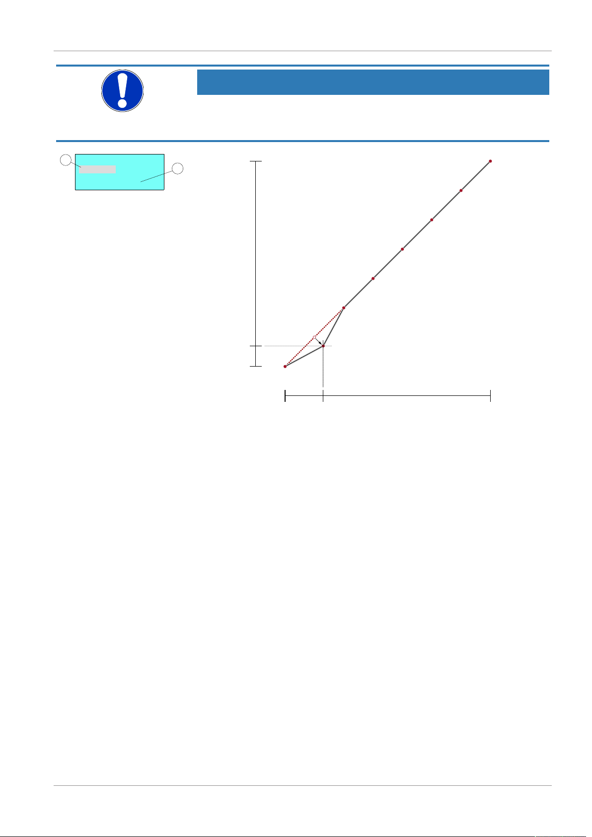
Tables function
This function allows free adjustment of the input variable to the display and output via a table with up to 30 support points. A value pair comprising a measured
value and display value is issued for every support point.
NOTICE
Change of parameter
When switching from TABLE to another function, the table is initialised again
and the existing values are lost.
Parameter name Description Value range
Function Function Value = Table
MB decimal pl. Measuring range
decimal places
MB start Measuring range start -9999 … +9999
MB end Measuring range end -9999 … +9999
MB unit Measuring range unit 4 characters
No. of pairs Number of pairs n = 3…30
Value pair1 Value pair 1
Value pair2 Value pair 2
Value pair3 Value pair 3
∙∙∙
Value pair30 Value pair 30
The display range is defined with the parameters MB decimal pl., MB start and
MB end. The user can select the configuration freely.
Using the parameter MB decimal pl., it is possible to select between a 5 or 6digit presentation. The resolution is not increased. Only an extra zero or two
zeros are added. This serves the correct display of larger values. The measuring range must be positive for the 6 digit presentation.
The MB unit gives the user the option of defining a completely independent
unit. Letters, numbers or special characters can be used. The unit can be max.
4 characters long.
If the function TABLE is selected, then it is also necessary to state the No. of
pairs. It is defined here how many pairs of values (support points) are used in
the table. A table is made up of at least 3, max. 30 support points.
1234, 123.4, 12.34,
1,234, 12345, 123456
MB-start … MB-end
20 / 36 BA_EN_EA14D
Page 21
FISCHER Mess- und Regeltechnik GmbH Start-up | 4
Value pair
2
+14,6 mbar +8,6 %
+0,0 ... +100,0 mbar
1
2
1 input mark (value flashes)
2 allowed range of values
Start End
Measuring range
Output / display [%]
100
0
0.0 100.0
Value pair 2
NOTICE
Number of value pairs
If the number of value pairs is changed, the table is initialised again and the existing values are deleted.
Fig.14: Value pair
Fig.15: Table function (example)
The individual value pairs can be seen and changed with the Value pair1 to
Value pair30 parameters. A value pair comprises a measured value (left side)
and a display value (right side). The measured value must lie within the measuring range and the display value must lie within the defined "free unit". The respective limits are shown during input. The table must contain either increasing
or decreasing values. the table must contain either continuously increasing or
continuously failing values. A change from an increasing to a decreasing characteristic curve within a support point table is not allowed.
4.5.6 Menu level function 2
This menu level only appears, if the 2-channel operating mode has been set.
The parameters on this menu level are identical to the parameters on the function menu level. Therefore the parameters are not described again here.
BA_EN_EA14D 21 / 36
Page 22

4 | Start-up FISCHER Mess- und Regeltechnik GmbH
4.5.7 Menu Level Display
The Display menu level is a variable menu whose appearance depends on the
value of the colour parameter. In addition to the various colours for the background lighting, there are also two auto-functions with colour switching available.
Parameter name Description Value range
Assignm. switch. Assignment of the colour
switch
Colour Colour Off, red, green, yellow,
Lighting Lighting time 0 s, 10 … 600 s
Contrast Contrast 15 … 45
Bar chart Bar chart display yes, no
Channel select. Channel selection Channel 1, channel 2,
Channel 1, channel 2
blue, pink, turquoise,
white,
Auto1: Red-green
Auto2: Red-yellowgreen
both channels
alternating 3s, 6s, 9s
The parameter Assignm. switch. is used to define an input channel to which
the colour change refers.
(1)
The most important parameter however is Colour.
A fixed colour can be defined for the background colour here. There are also
two auto-functions with colour switching available. Alternatively, the background
illumination can be permanently deactivated.
If permanent lighting is not required, the parameter Lighting can be used to
define when the lighting should be switched off after the last time a button is
pressed. In addition to permanent lighting (0 s), automatic shut-down after 10…
600 s is also possible. The set time is only valid if the parameter Colour is not
set to "off".
Amongst other things, the legibility of the display depends on the temperature
and the reading angle. To ensure optimised legibility, the display can be adjusted using the parameter Contrast. When the contrast is changed, it is possible
that the display appears empty or almost completely black. In this case, the
contrast must be turned up or down.
Via the parameter Bar chart, the display can be switched between a display
where the measured value is either shown in large digits or the display shows
small digits and an additional bar chart.
The Channel select. parameter offers the user the option of deciding which of
the measured values need to be shown on the display. The following values can
be entered for the parameter:
• Channel 1
• Channel 2
• Both channels
• alternating 3s, 6s or 9s
The time that a measurement is shown on the display can be set with the value
'alternating. The channel is changed after this time.
(1)
This parameter only appears if a colour change function has been selected.
22 / 36 BA_EN_EA14D
Page 23

FISCHER Mess- und Regeltechnik GmbH Start-up | 4
Basic measuring range
ME
F1 F2
MA
Auto1: Colour-change red to green
If parameter Colour is set to Auto 1: red-green, the menu changes as follows:
Parameter name Description Value range
Assignm. switch. Assignment switching Channel 1, channel 2
Red-Gr. switch. Red-green switching MB-start - 50% …
Gr-Red switch. Green-red switching
Hysteresis Hysteresis 0.1 … 10.0 %
Delay Delay 0 … 1800 s
Colour Colour Off, red, green, yel-
Lighting Lighting time 0 s, 10 … 600 s
Contrast Kontrast (contrast) 15 … 45
Bar chart Barchart display yes, no
Channel select. Channel selection Channel 1, channel 2
The parameter Assignm. switch. is used to define an input channel to which
the colour change refers.
In the Auto 1 mode with the automatic colour switchover, the parameters Red-
Gr. switch. or Gr-Red switch. serve to enter the required thresholds. The col-
our change F1 and F2 can be moved anywhere within the measuring range.
The series of colour changes however cannot be altered.
MB-end + 50%
low, blue, pink, turquoise, white,
Auto1: Red-green
Auto2: Red-yellowgreen
Fig.16: Function Auto1
MA MB-start Measuring range start
F1 Red-Gr. switch. Red-green switching
F2 Gr-Red switch. Green-red switching
ME MB-end Measuring range end
The parameter Hysteresis can be used to prevent fast and unwanted colour
changes. The hysteresis is set in the range 0.1... 10 %.
NOTICE
Overlapping colour areas
Note: In the case of large hysteresis values, steps must be taken to ensure that
the ranges of the individual colours do not overlap. Otherwise it is possible that
the colour change may not function in the desired way.
The parameter Delay offers a further option to prevent unwanted colour
changes. The colour change here can be delayed between 0…1800 s.
The parameters Lighting, Contrast, Bar chart and Channel select. are explained in the previous section.
BA_EN_EA14D 23 / 36
Page 24

4 | Start-up FISCHER Mess- und Regeltechnik GmbH
Basic measuring range
MA ME
F1 F2 F3 F4
Auto2: Colour-change red-yellow-green
If the parameter Colour is set to Auto 2: red-yellow-green, the menu changes as
follows:
Parameter name Description Value range
Assignm. switch. Assignment switching Channel 1, channel 2
Red-Yell.switch. Red-yellow switchover
Yell.-Gr.switch. Yellow-green switchover
Gr.-Yell. switch Green-yellow switchover
Yell.-Red switch Yellow-red switchover
Hysteresis Hysteresis 0.1 … 10.0 %
Delay Delay 0 … 1800 s
Colour Colour Off, red, green, yel-
Lighting Lighting time 0 s, 10 … 600 s
Contrast Kontrast (contrast) 15 … 45
Bar chart Barchart display yes, no
Channel select. Channel selection Channel 1, channel 2
MB-start - 50% …
MB-end + 50%
low, blue, pink, turquoise, white,
Auto1: Red-green
Auto2: Red-yellowgreen
In the Auto 2 mode with the automatic colour switchover, it is possible to enter
the required switch thresholds via the parameters Red-Yell.switch., Yell.-
Gr.switch., Gr.-Yell. switch, Yell.-Red switch The colour change F1, F2, F3
and F4 can be moved anywhere within the measuring range. The series of colour changes however cannot be altered.
Fig.17: Function Auto2
MA MB-start Measuring range start
F1 Red-Yell.switch. Colour-change red to yellow
F2 Yell.-Gr.switch. Colour-change yellow to green
F3 Gr.-Yell. switch Colour-change green to yellow
F4 Yell.-Red switch Colour-change yellow to red
ME MB-end Measuring range end
NOTICE
Unused range
If a range is not to be used, the associated switch thresholds (F1…F4) can be
set to the same value.
24 / 36 BA_EN_EA14D
Page 25

FISCHER Mess- und Regeltechnik GmbH Start-up | 4
Basic measuring range
MA ME
F1
F2
F3 F4
Example
The parameter Colour is set to Auto2. Only the green, yellow and red ranges
are required here. To fade out the lower ranges red and yellow, the switch
thresholds "red-yellow switching" and "yellow-green switching" are set to the
start of the measuring range.
Fig.18: Example Auto2
The parameters Hysteresis, Delay, Lighting, Contrast, Bar chart and Chan-
nel select. are explained in the previous sections.
4.5.8 Menu Level System
Parameter name Description Value range
Language Language change DE, EN, FR, ES,
Software Info Information about the software Device type, serial
Config. Info Information about the configur-
Statistics Statistics Operating time,
Password Password 0/1…999
Load config. Load configuration
Save config. Save configuration
ation
IT,PT,HU
number, firmware
version
Basic measuring
range, output signal,
contacts
switch cycles of the
contacts
The user menu can be switched to German, English, French, Spanish, Italian,
Portuguese or Hungarian using the parameter Language.
The menu items Software Info and Config. Info provide information about the
device. This information helps to answer questions about the device quickly.
• The serial number and the firmware version is shown in Software info. If a
'designation' has been assigned, this is also issued. Please note that a 'designation' can only be entered with the PC software by remote configuration.
• The basic measuring range, the defined output signal and existing contacts
are stated in the Config. Info.
The Statistics provide information about the operating time and the relay
switching cycles from the time of delivery. The operating time is shown in days
(d) and hours (h)
A Password can be used to protect the menu against unauthorised access.
The password is a figure from 1 to 999. The input 0 means that no password is
active.
BA_EN_EA14D 25 / 36
Page 26

4 | Start-up FISCHER Mess- und Regeltechnik GmbH
The password needs to be set if the user presses the button in normal mode to
enter the menu. If a wrong password is entered, the system automatically jumps
back to normal mode again. If no password is active, the display immediately
jumps to the menu.
NOTICE
Forgotten password
The user cannot restore a forgotten password. Please contact the manufacturer
in this case.
The user can load a saved configuration via the menu item Load config. This
means that a functional set of parameters can be loaded after trying out various
settings.
The menu item Save config. serves to save the existing parameters in a protected memory area. This is helpful if the settings of a functional device needs
to be optimised. Save config. and Load config. can be used to quickly restore
the initial status again.
NOTICE
Delivery condition
If the user has not yet saved a configuration, the default values (status on delivery) are loaded. In this case, any measuring range spreads or switch points are
reset and the device needs to be newly configured.
26 / 36 BA_EN_EA14D
Page 27

FISCHER Mess- und Regeltechnik GmbH Servicing | 5
5 Servicing
5.1 Maintenance
The instrument is maintenance-free. We recommend the following regular inspection to guarantee reliable operation and a long service life:
• Check the function in combination with downstream components.
• Check the leak-tightness of the pressure connection lines.
• Check the electrical connections.
The exact test cycles need to be adapted to the operating and environmental
conditions. In combination with other devices, the operating instructions for the
other devices also need to be observed.
5.2 Transport
The measuring device must be protected against impacts. It should be transported in the original packaging or a suitable transport container.
5.3 Service
All defective or faulty devices should be sent directly to our repair department.
Please coordinate all shipments with our sales department.
WARNING
Process media residues
Process media residues in and ondismantled devices can be a hazard to
people, animals and the environment. Take adequate preventive measures. If
required, the devices must be cleaned thoroughly.
Return the device in the original packaging or a suitable transport container.
5.4 Disposal
Please help to protect the environment by always disposing of the work pieces
and packaging materials in compliance with the valid national waste and recycling guidelines or reuse them.
BA_EN_EA14D 27 / 36
Page 28

6 | Technical data FISCHER Mess- und Regeltechnik GmbH
6 Technical data
6.1 Generalities
The stated technical data only refer to the differential pressure evaluation unit
EA14D and never take into account the properties of the connected pressure
transmitter.
6.2 Input variables
Analogue input
(Pressure transmitter signal)
Current signal in compliance with DIN IEC
60381-1
Voltage signal in compliance with DIN IEC
60381-2
Differential pressure measuring range
0 … 2.5 bar
0 … 6 bar
0 … 10 bar
0 … 16 bar
0 … 25 bar
0 … 40 bar
0 … 60 bar
Other measuring ranges available on request.
Channel 1 and2Type of con-
0 … 20 mA 3-Wire
4 … 20 mA 2-Wire
0 … 10 V 3-Wire
6.3 Output sizes
Switch output
(potential-free)
Progr. switching function Open contact (NO)
Max. switching voltage 32 V AC/DC 3 … 32 V AC/DC
Max. switching current 2 A 0.25 A
Max. switching output 64 W(VA) 8 W(VA)
Relay MOSFET
One-pin activator (NO)
Break contact (NC)
One-pin deactivator (NC)
RON ≤ 4 Ω
nection
Optionally, the device can also be supplied with two analogue outputs.
Analogue output 0/4 … 20 mA 0 … 10 V
Type of connection 3-Wire 3-Wire
Apparent ohmic
resistance
Signal range 0.0 … 21.0 mA 0.0 … 11.0 V
Turn down 10:1 10:1
28 / 36 BA_EN_EA14D
Ub ≤ 26 V: RL ≤ (Ub – 4 V) / 0.02 A RL > 2 kΩ
Ub > 26 V: RL ≤ 1100 Ω
Page 29

FISCHER Mess- und Regeltechnik GmbH Technical data | 6
6.4 Measurement accuracy
Maximal Typical
Measurement deviation
Temperature drift
+)
x)
Span 0.1 %FS/10K <0.025 %FS/10K
0.1 % FS <0.05 %
Zero point 0.1 %FS/10K <0.025 %FS/10K
+)
Characteristic curve deviation (non-linearity and hysteresis) at 25°C and rated
voltage basic measuring range with linear characteristic curve, not spread
x)
In relation to the basic measuring range with a linear, not spread, character-
istic curve.
6.5 Auxiliary energy
Rated Voltage 24V AC/DC
Admissible operating voltage 12 … 32 V AC/DC
Absorbed power Max. 2 W (VA)
6.6 Operating conditions
Ambient temperature range -10 … +70 °C
Storage temperature range -20 … +70 °C
Medium temperature range see Pressure sensor data sheet
Protection class IP IP65 acc. to DIN EN 60529
EMC EN 61326-1
EN 61326-2
RoHS EN 50581
6.7 Display and operating interface
Annunciation, display, indication
4...6-digit LCD, full graphic, colour backlighting
Programming
Damping 0.0…100.0s (jump response 10/90%)
Switch output Switch-off point, switch-on point, response time
(0...1800s), function (NC / NO contact), channel assignment
Measuring range unit bar, mbar, Pa, kPa, MPa, psi, InWc, mmWs, mmHg,
'free unit', starting value, end value and decimal point
for 'free unit'
Output signal User-definable within the basic measuring range
Zero-point window 0…⅓ of the basic measuring range
Offset correction ±⅓ of the basic measuring range
Implementation of char-
linear, square rooted, table with 3...30 support points
acteristic curve
Password 001 ... 999 (000 = no password protection)
Language (can be
DE, EN, FR, ES, IT, PT, and HU
switched)
(1) Max. effective spread 10:1
(2) measured values around zero are set to zero.
(3) To compensate different installation positions.
(2)
(3)
(1)
BA_EN_EA14D 29 / 36
Page 30

6 | Technical data FISCHER Mess- und Regeltechnik GmbH
6.8 Construction design
Process connection 2 x 5-pin round plugs M12 (female) for ex-
ternal pressure transmitters or
2 x 4-pin standard plug DIN EN 175
301-803-A (female) with 1 m cable
Electrical connection 2 x round plug connector M12 (male)
5-pin for supply and output signal
4-pin for switch contacts
Installation position User-defined
Dimensions (LWH) 90 x 61.5 x 75 mm
Weight
(without cables and pressure
sensors)
300 g
6.8.1 Materials
Materials of the parts that come
into contact with the medium
see Pressure sensor data sheet
Materials of the parts that come
into contact with the surroundings
Housing Polyamide PA 6.6
Foil keypad Polyester
Process connection Nickel-plated brass
Electrical connection Polyamid
30 / 36 BA_EN_EA14D
Page 31

FISCHER Mess- und Regeltechnik GmbH Technical data | 6
90
75
76
70.5
61.5
83
94
Ø5
M12 Buchse
Standard plug DIN 175 301-803
with 1 m cable
M12 plug
plug 2 plug 1
Wall mounting plate
78
63
Ø5
94
83
76
87
9
2
Rear view
without wall mounting plate
Wall mounting plate
boreholes for
tapping screws Ø3.5
6.8.2 Dimensional drawings
Fig.19: Dimensional picture
6.8.3 Wall mounting
Fig.20: Wall mounting
BA_EN_EA14D 31 / 36
Page 32

6 | Technical data FISCHER Mess- und Regeltechnik GmbH
Adapter element
38
36
2525
40
61.5
TS35
TS35
TS15
TS32
40 36
35
35
15
32
16242121
7.5
155
15
6.8.4 Assembly of the mounting rails
Fig.21: Adapter element
32 / 36 BA_EN_EA14D
Fig.22: Mounting rails options
Page 33
FISCHER Mess- und Regeltechnik GmbH Technical data | 6
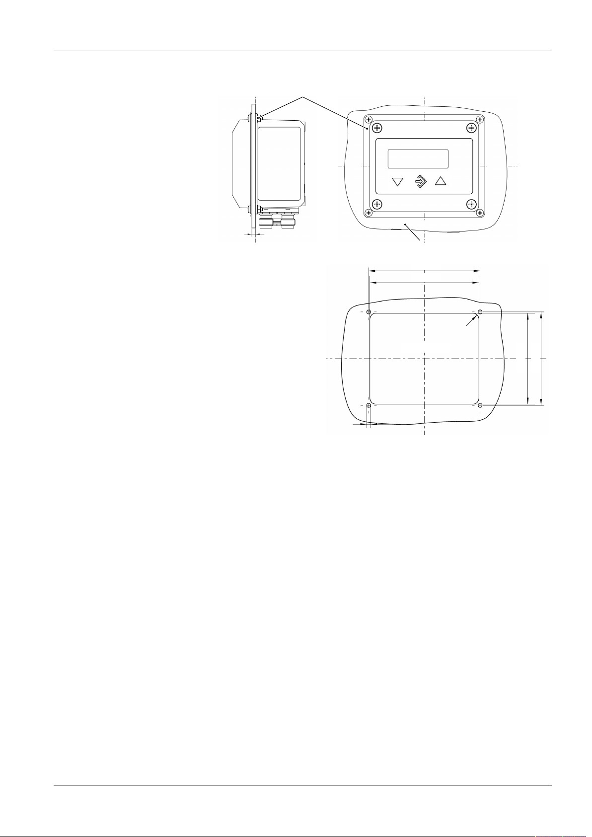
Wall thickness 3 ... 5 mm
panel mounting set
Front plate
92 ± 0.2
90 ± 0.2
75 ± 0.2
75 ± 0.2
3.3
R5
Panel cut-out
6.8.5 Installation of front panel
Fig.23: Installation of front panel
BA_EN_EA14D 33 / 36
Page 34

7 | Order codes FISCHER Mess- und Regeltechnik GmbH
E A 1 4 K W MD 0
1 2 5 6 7 8 9 10 11 123 4
Process connection
Output signal
Operating voltage
Measuring unit
Electrical connection
Assembly
Type
Measuring range
Code no.
Input signal
Differential pressure
7 Order codes
[3.4] Measuring range (differential pressure)
04 0 … 2.5 bar
06 0 … 6 bar
07 0 … 10 bar
08 0 … 16 bar
09 0 … 25 bar
10 0 … 40 bar
11 0 … 60 bar
99 Other measuring ranges available on request
[5] Process connection (pressure transmitter)
M 2 x M12 plug connection
H 2 x plug connector DIN EN 175301-803 A with 1m cable
[6] Input signal (pressure transmitter) Type of connection
A 0 … 20 mA 3-Wire
B 4 … 20 mA 2-Wire
C 0 … 10 V 3-Wire
[7] Output signal Type of connection
0 Without analogue output signal
4 0 … 20 mA 3-Wire
5 0 … 10 V 3-Wire
6 4 … 20 mA 3-Wire
[8] Operating voltage
K 24 V AC/DC
[9] Measuring unit
W Selectable pressure units
[10] Measured value display / contact elements:
C 4-digit colour change LCD / 2 relay contacts
D 4-digit colour change LCD / 2 semiconductor contacts
[11] Electrical connection
M 2 x M12 plug connection
34 / 36 BA_EN_EA14D
Page 35

FISCHER Mess- und Regeltechnik GmbH Order codes | 7
[12] Assembly
0 Attachment boreholes on rear side (standard)
W Wall mounting
T Panel mounting set
S Assembly of the mounting rails
7.1 Accessories
Order no. length
4-pin M12 Connection cable for switching outputs
06401993 2m
06401994 5m
06401563 7m
06401572 10m
5-pin M12 connection cable for auxiliary energy and analogue outputs
06401995 2m
06401996 5m
06401564 7m
06401573 10m
Remote configuration
Order no.
EU05 0000 Transmitter PC interface incl. PC software without battery
EU05 0001 With battery
EU03 F300
A data sheet is available on our website www.fischermesstechnik.de or on request.
BA_EN_EA14D 35 / 36
Page 36

8 | EU Declaration of Conformity FISCHER Mess- und Regeltechnik GmbH
8 EU Declaration of Conformity
Fig.24: CE_DE_EA14D
36 / 36 BA_EN_EA14D
 Loading...