

Page 1
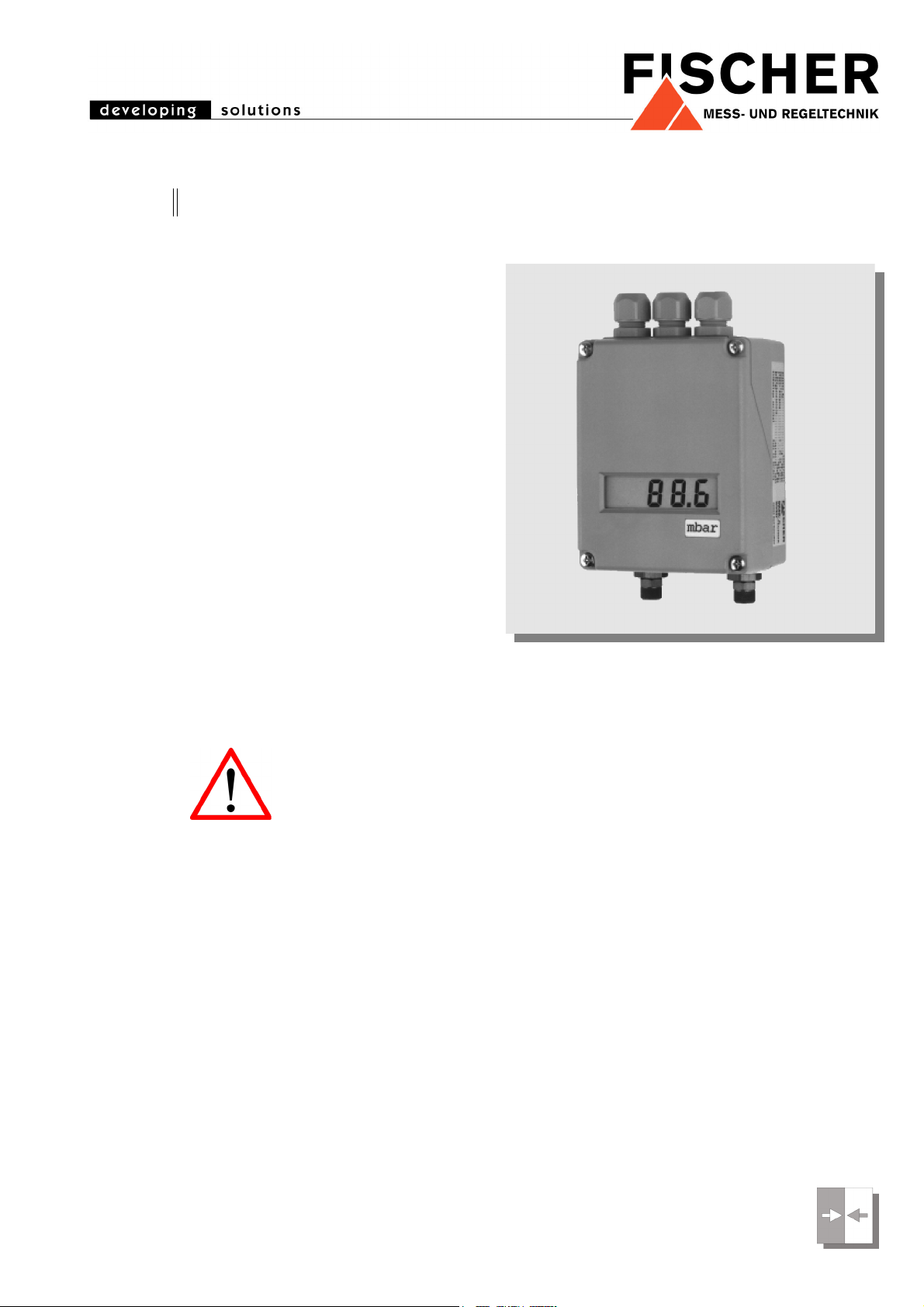
Instruction Manual
DE61 Differential Pressure Transmitter
Table of Contents
1. Safety Instructions
2. Intended Applications
3. Product Description and Functions
4. Installation
5. Commissioning
6. Maintenance
7. Transport
8. Service
9. Accessories
10. Disposal
11. Specifications
12. Dimensions
13. Ordering Code
14. CE-Certificate
1. Safety Instructions
1.1. General
personnel responsible for the equipment must
read this thoroughly before attempting to install or
operate this equipment. A copy of this manual
must always be kept accessible at the place of
work for reference by concerned personnel.
Chapter 1 (sections 1.2 through 1.7) contains general as well as specific safety instructions. Chapters 2 through 10, covering topics ranging from
intended purpose of the equipment to its final disposal, also include important points relating to
safety. Overlooking or ignoring any of these safety
16.10.07 BA_GB_DE61.fm
points can endanger humans and animals, and
possibly cause damage to other equipment.
1.2. Personnel Qualification
Personnel responsible for installation, operation,
maintenance and inspection of this product must
have the qualifications, training and experience
necessary to carry out such work on this type of
equipment.
This manual contains detailed
information about the product,
and instructions for its installation, operation and maintenance.
Operators and other technical
1.3. Risks of Disregarding Safety Instructions
Disregarding safety instructions, use of this product for purposes for which it is not intended, and/
or operation of this product outside the limits specified for any of its technical parameters, can result
in harm to persons, the environment, or the plant
on which it is installed. Fischer Mess- und Regeltechnik GmbH will not be responsible for consequences in such circumstances.
1.4. Safety Instructions for Operators
Safety instructions for the proper use of this product must be followed. This information must be
available at all times to by personnel responsible
for installation, operation, maintenance and inspection of this product. Adequate steps must be
taken to prevent the occurrence of hazardous conditions that can be caused by electric energy and
the convertible energy of the process media. Such
conditions can, for example, be the result of improper electrical or process connections. Detailed information is available in relevant published norms
(DIN EN, UVW in Germany; and equivalents in
other countries), industrial standards
such as DVWG, Ex-, GL-, VDE guidelines, as well as regulations of the local
authorities (e.g., EVUs in Germany).
Page 2

1.5. Modifications Forbidden
Modification or other technical alteration of the product is
not permissible. This also applies to the use of unauthorized spare parts for repair / maintenance of the product.
Any modifications to this product, if and as necessary,
should be done only by Fischer Mess- und Regeltechnik
GmbH.
1.6. Operational Restrictions
The operational reliability of the product is guaranteed
only when used for intended purposes. The product must
be selected and configured for use specifically with defined process media. The limiting values of operating parameters, as given in the product specification sheet,
must never be crossed.
1.7. Safety Considerations during Installation and Maintenance
The safety instructions given in this manual, existing national regulations relating to accident prevention, and the
internal safety rules and procedures of the user organization regarding safety during installation, operation and
servicing must all be followed meticulously.
It is the responsibility of the users to ensure that only suitably qualified and experienced technical personnel are
used for installation, operation and servicing of this
equipment.
2. Intended Applications
Measuring transmitter with limit switching functions for
acquisition and transmission of lowest pressure and differential pressure. The product must be used only for applications and under conditions specified by the
manufacturer. Please confer with Fischer Mess- und Regeltechnik GmbH prior to using this transmitter along with
polluted or aggressive media. For use with this media it
needs to be adjusted in every part with direct contact to
the media.
3. Product Description and Functions
3.1. Block Schematic Diagram
1
2
3
4
3.2. Principles of Operation
The function of this transmitter is based on a capacitive
sensor element. Due to modern micromechanical manufacturing process this sensor is highly overpressure safe,
shock and vibration resistant and long-time stable.
The differential pressure acts on the sensor element and
effects a measuring signal. The electronic amplifier then
generates an electrical output signal of 0 / 4-20 mA. This
output signal is used for external data processing and is
shown on the LC-display e.g. in mbar.
The LC-display can also be used for indication and precise adjustment of the differential pressure dependent
switching functions. Both change-over contacts can be
adjusted to any value within the measuring range.
4. Installation
4.1. Process connections
• Only qualified technicians authorized for this type of
work should undertake installation.
• Only for intended mechanical process connection (for
model information see Type Plate of instrument).
• Ensure that process equipment and pressure lines
are at atmospheric pressure before making pressure
connections.
• The instrument should be provided with suitable protection against pressure surges (e.g., snubber or pulsation damper).
• Ensure that the mechanical configuration and materials of construction of the instrument are compatible
with the process media.
• Ensure that process pressure is always less than the
specified safe pressure rating.
4.2. Electrical Connections
• Only qualified technicians authorized for this type of
work should undertake installation.
• Electrical connections must comply with relevant international, national and local regulations and norms
relating to electrical and instrumentation installations.
• Switch off electrical power to the plant before attempting electrical installation work of any kind.
• Make electrical connections to the transmitter through
a suitable energy-limiting safety device (isolation or
zener barrier).
Sensor element
1. Signal output
2. Option square rooted
3. 2 change-over
contacts
4. LC-display
5. Commissioning
• Power supply and signal cabling to the transmitter
must be correctly selected to meet operational requirements, and installed in a way that does not cause
physical stress to the instrument.
• Carefully check tightness of all pressure connections
before start-up.
2
Page 3
5.1. Pressure Connections
The instruments pressure ports are marked by + and −
symbols. The pressure applications need to be installed
according to the label.
• Differential pressure + = higher pressure
measurement: − = lower pressure.
• Pressure measurement + = pressure port
• Gauge measurement − = negative pressure port
5.2. Shock Pressure Moderation
During pulsating pressure on the plant mechanical wear
and disturbances in functional capability may occur. To
avoid this we recommend installing absorbers into the
pressure lines.
For Gaseous Media
Adjustable attenuator
valve MZ41
During operating condition adjust needle valve that way,
that the indicator follows changements of pressure delayed.
MZ41
• Connect and switch on power supply.
• Measuring system depressurized: Output signal = 0
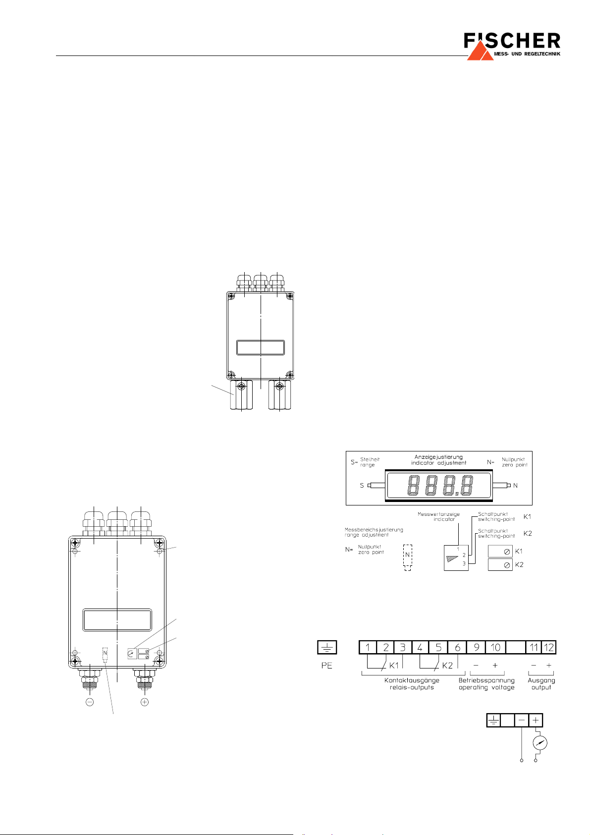
resp. (4) mA. Correct offset using zero point potentiometer N.
• Mount housing cover.
5.4. Switching Point Adjustment
The instrument’s main board has two calibration potentiometers and a coding switch to set switching points. After removing housing cover they are freely acessible.
Adjustment sequence
• Switch on supply voltage.
• Open housing cover.
• Selector setting 1: Display indicates actual value.
• Selector setting 2: Display indicates switching point I.
• Selector setting 3: Display indicates switching point II.
• The respective setpoint values for contact 1 and contact 2 can be set in display using potentiometers K1
and K2.
• After adjustment is done turn selector to setting 1: actual value.
• Setpoint values can be displayed any time by turning
selector to position 2 or 3.
5.3. Zero Point Adjustment
Usually adjustment of the instrument is not necessary for
it is factory calibrated. The output signal can be adjusted
with inbuilt zero point potentiometer.
Location of zero point potentiometer
Mounting holes
Selector
Switching point
potentiometer
Range adjustment: N = Zero point
Selector and Set-up Potentiometer
Selector
5.5. Electrical Connection
3-wire connection 24 V DC
2-wire connection 24 V DC
Adjustment sequence
• Open housing cover.
• Connect current indicator (0-20 mA) to output signal
between terminals 11 and 12.
3
Page 4

6. Maintenance
The instrument is inherently maintenance-free.
However, to ensure reliable operation and maximize the
operating life of the instrument, it is recommended that
the instrument, its external electrical and process connections, and external connected devices be regularly inspected, e.g.:
• Check the display.
• Check the switching function in connection with secondary components.
• Check all pressure connections for leak-tightness.
• Check the integrity of all electrical connections of the
instruments.
Inspection and test schedules depend on operating and
site conditions. The operating manuals of other equipment to which the differential pressure transmitter is connected must be read thoroughly to ensure that all of them
work correctly when connected together.
7. Transport
The product must be protected against shock and vibration during transport. It must therefore be properly pakked, preferably in the original factory packaging,
whenever it is to be transported.
8. Service
Any defective devices or devices with missing parts
should be retourned to Fischer Mess- und Regeltechnik
GmbH. For quick service contact our service department.
Remaining medium in and on dismantled measuring instruments may cause
danger to persons, environment and
equipment. Take reasonable precau-
tions! Clean the instrument thoroughly if necessary.
9. Accessories
10. Disposal
Protect your environment!
Use the product in accordance with relevant regulations. Please be aware of
environmental consequences of disposal at the end of the product's life, and
take care accordingly.
4
Page 5

11. Specifications
General
Measuring ranges 0...0.25 to 0...4.0 mbar (see 13. Ordering Code)
Nominal pressure 0.6 bar
Max. static pressure overpressure safe up to permitted nominal pressure
Linearity 1% FS
Hysteresis 0.1% FS
Temperature drift 0.5% FS / 10K
Perm. ambient temperature -10°...60°C
Perm. medium temperature -20°...70°C
Protection class IP 54 per DIN EN 60529
Electrical
Electrical connections 3-wire 3-wire 2-wire
Operating voltages 24 V DC 24 V DC 24 V DC
Power consumption approx. 3 VA approx. 3 VA approx. 3 VA
Output signal 0-20 mA 4-20 mA 4-20 mA
Apparent ohmic resistance 700 Ω 700 Ω max. 450 Ω
Current limit approx. 30 mA approx. 30 mA approx. 30 mA
Square-rooted output ± 0.5%
with suppression of leak flow volume 2% set up
Span adjustment approx. 10% FS
Zero point adjustment approx. 10% FS
Measuring Indication /
Switching Sections
Measuring indication 3½ digit LC-Display
Switching point adjustment The digital display can be switched over between the differential pressure
actual value and the switch point adjustments via selector. The display then
indicates the related setpoint value. Setpoint values are adjustable within full
scale range.
Switching point hysteresis approx. 2%
Contact output 1 or 2 potential-free change-over contacts
Load data of contacts
U~
U=
Connection
Electrical Connections internal connector bloc, M16x1.5 connection
M12 plug connection
Pressure Connections female thread G¼, threaded hose coupling (al) for 6/8 mm flexible tube,
cutting ring connection (brass) for 6/8/10 mm tube
Materials
Housing diecasted aluminium, varnished
Housing cover ABS, self-extinguishing
Measuring element silicium, glass, aluminium
Installation
wallmounting vertical, pressure ports downward
any other orientation correction of zero point recommended
= 250 V AC, I~
max.
= 30 V, I=
max.
max.
= 2 A, P=
max.
= 2 A, P~
max.
= 250 VA ohmic resistance
max.
= 60 W ohmic resistance
5
Page 6
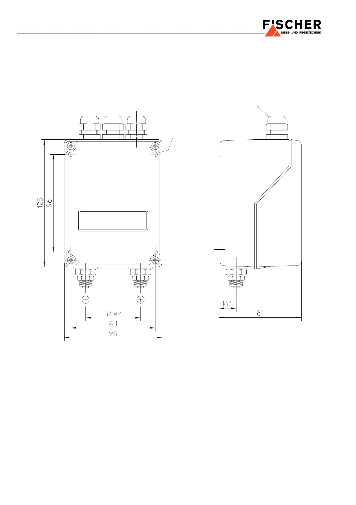
12. Dimensions (all units in mm unless stated otherwise)
Mounting holes
∅ 4.5 mm
Cable gland M16 x 1.5
6
Page 7
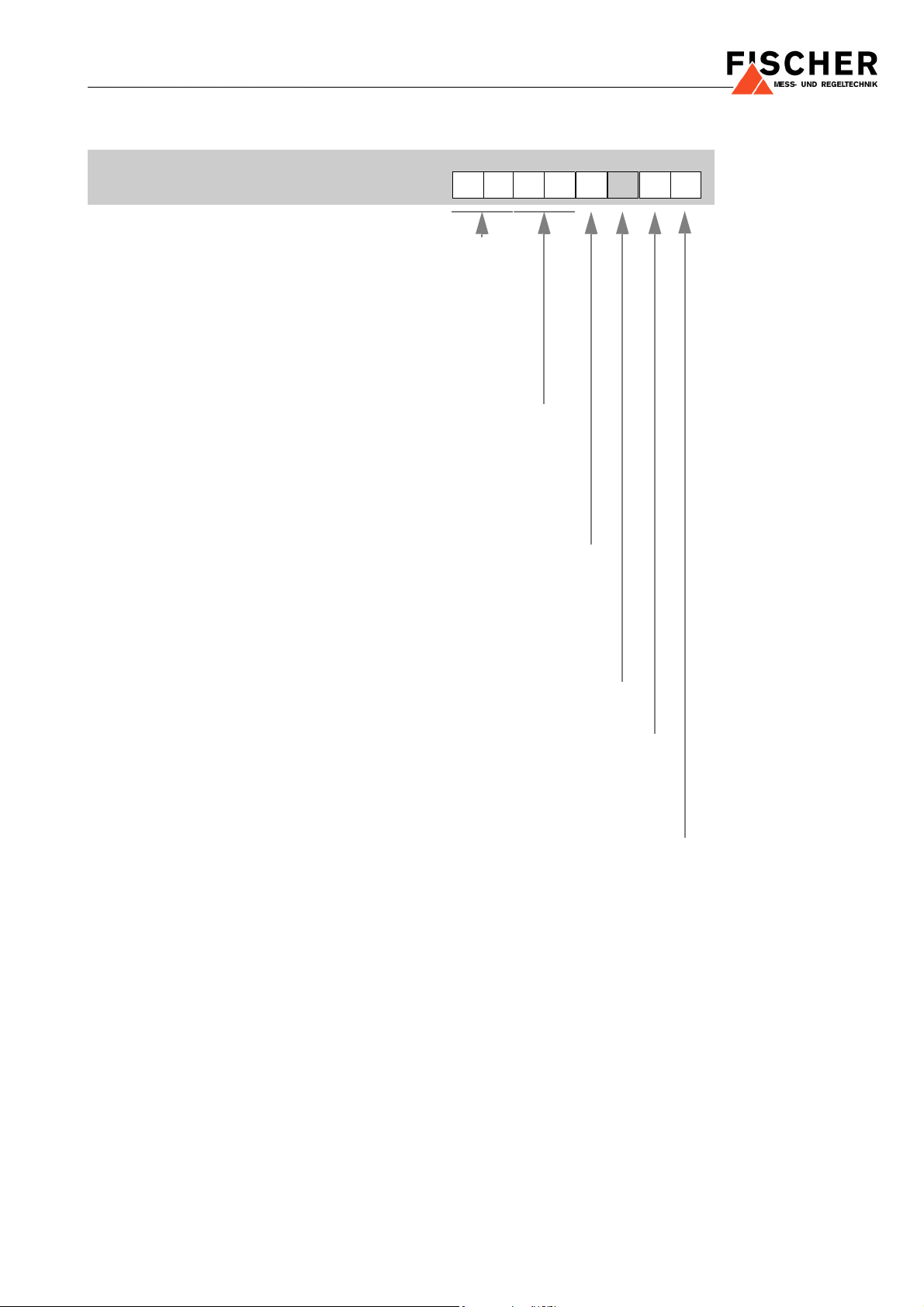
13. Ordering Code
Differential Pressure
Transmitter DE61
Measuring Range
0...0.25 mbar....................................................................> 9 4
0...0.4 mbar....................................................................> 9 5
0...0.6 mbar....................................................................> 9 6
0...1.0 mbar....................................................................> 5 1
0...1.6 mbar....................................................................> 9 7
0...2.5 mbar....................................................................> 9 8
0...4.0 mbar....................................................................> 5 2
other measuring ranges (please indicate in plain text) ....> 9 9
Pressure Connection
Female thread G ¼..........................................................................> 0 1
Cutting ring connection brass for 6 mm tube...................................> 2 8
Cutting ring connection brass for 8 mm tube...................................> 2 9
Cutting ring connection brass for 10 mm tube.................................> 3 0
Screw connection AI for 6 mm flexible tube.....................................> 4 0
Screw connection AI for 8 mm flexible tube.....................................> 4 1
Electrical Output Signal
0–20 mA linear, 3-wire.....................................................................................> A
4–20 mA linear, 2-wire, only 24 V DC, without contacts and square-root
extraction .........................................................................................................> B
0–20 mA square-rooted, 3-wire .......................................................................> E
4–20 mA square-rooted, 3-wire .......................................................................> F
4–20 mA linear, 3-wire.....................................................................................> P
9
Supply Voltage
24 V DC ....................................................................................................................> 9
Indication / Switching Sections
Without indication / without contacts.................................................................................> 0
3½ digit LC-display / without contacts...............................................................................> 1
3½ digit LC-display / with 1 potential-free contact ............................................................> 2
3½ digit LC-display / with 2 potential-free contacts...........................................................> 5
Electrical Connection
Internal connector bloc .............................................................................................................> E
M12 plug connection.................................................................................................................> M
7
Page 8
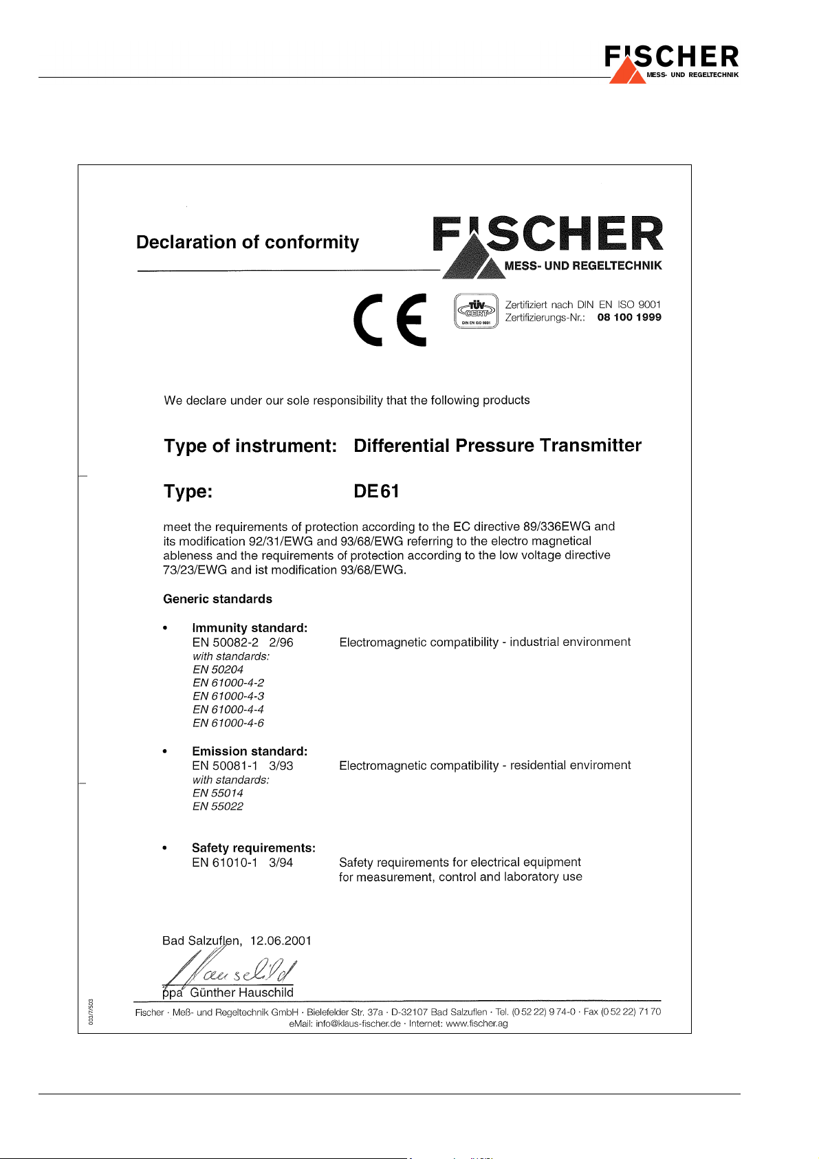
14. CE-Certificate
Technische Änderungen vorbehalten • Subject to change without notice • Changements techniques sous réserve
Fischer Mess- und Regeltechnik GmbH • Bielefelder Str. 37a • D-32107 Bad Salzuflen • Tel. +49 5222 9740 • Fax +49 5222 7170
eMail: [email protected] • www.fischermesstechnik.de
8
 Loading...