

Page 1
Inductive displacement
transducer
Capsule element
1.
2.
3.
4.
1. Load
2. Load
3. 2 change-over contacts
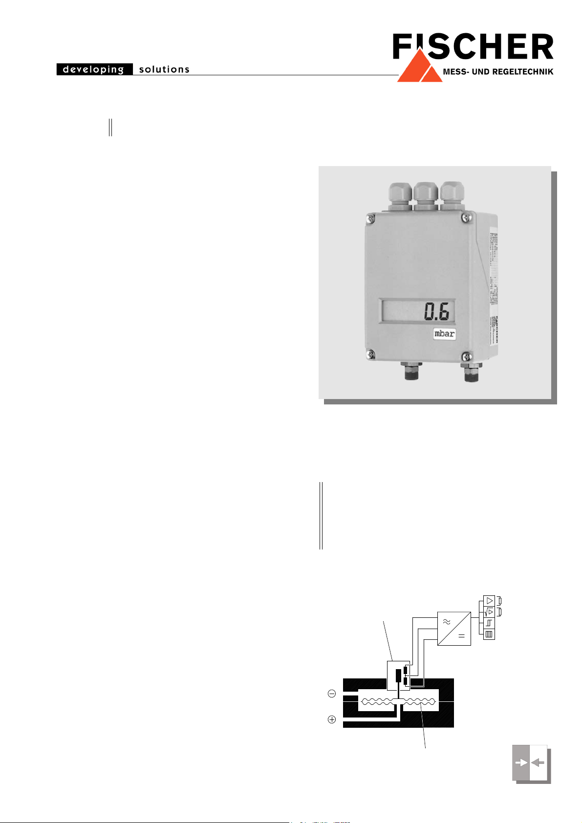
4. LC-display
DE50 Differential Pressure Transmitter
Measuring transmitter with limit switching function for overpressure, vacuum
and differential pressure especially for
gaseous media
Range of applications:
• air conditioning technology
• ventilation technology
• environmental engineering
Typical Applications
• continuous ventilating control
• monitoring of exhausters, tapline filters etc.
• chimney draft measurement
• flow and control pressure measurement
• surface technology
3.6.08 DB_GB_DE50.fm
Principles of Operation
The function of this transmitter is based
on a capsule element measuring system
suitable for overpressure-, vacuum- and
differential pressure measurements.
Pressure or differential pressure to be
measured displaces the capsule element and moves hereby the core of inductive displacement transducer. The
electronic amplifier generates an electrical output signal. Different types of electronic converters can be supplied. Apart
from the different operating voltages
output signal can be supplied as current
or voltage signal. Flow rates of gaseous
medium are often measured by measuring differential pressure. In order to obtain a flow proportional measuring value
differential pressure signal has to be
square-root extracted. For those applications transformation electronics are
used which supply square-root extracted output signals.
In addition to analogue output signal potential free relay outputs can be supplied. They can be adjusted to any value
within the measuring range. By means
of a built-in LC-display (option) a local linear indication
of pressure-/differential pressure measuring values is
possible.
Main Features
• high overpressure safety
• maintenance-free due to wear resistant inductive
measuring cell
• rugged design
Functional Scheme
Page 2

Specifications
General
Measuring ranges 0...4mbar to 0...600 mbar (see Ordering Code)
Nominal pressure max. 3 bar (see Ordering Code)
Max. static pressure overpressure safe up to permitted nominal pressure
Measuring accuracy ± 1% FS
Temperature drift 0.5% FS / 10K
Perm. ambient temperature -10°...+60°C
Perm. medium temperature -20°...+70°C
Protection class IP 54 acc. to DIN EN 60529
Electrical
Electrical connections 4/3-wire 4/3-wire 2-wire
Operating voltages 230 V AC 4-wire
115 V AC 4-wire
24 V AC 4-wire
24 V DC 3-wire
Power consumption approx. 3 VA approx. 3 VA ≤ 0,75 W
Output signal 0-20 mA 0-10 V DC 4-20 mA
Apparent ohmic resistance max. 800 Ω > 2 k Ω max. 500 Ω
Current limit approx. 30 mA approx. 30 mA approx. 30 mA
Voltage limit - approx. 12 V DC -
Square-rooted output ± 0.5%
with suppression of leak flow volume 2% set up
Range adjustment approx. 10% FS
Zero point adjustment approx. 10% FS
Measuring Indication /
Switching Sections
Measuring indication 3½ digit LC-Display
Switching point adjustment The digital display can be switched over between the differential pressure
actual value and the switch point adjustments via selector. The display then
indicates the related setpoint value. Setpoint values are adjustable within full
scale range.
Switching point hysteresis approx. 2%
Contact output 1 or 2 potential-free change-over contacts
Load data of contacts
U~
U=
Connection
Electrical Connections internal connector bloc, M16x1.5 connection
plug connections on request
Pressure Connections female thread G¼, threaded hose coupling (al) for 6/8 mm flexible tube,
cutting ring connection (brass) for 6/8/10 mm tube
Materials
Housing diecasted aluminium, varnished
Housing cover ABS, self-extinguishing
Measuring element capsule element of Cu Be 2
Installation
wallmounting vertical, pressure ports downward
any other orientation correction of zero point recommended
= 250 V AC, I~
max.
= 30 V, I=
max.
max.
= 2 A, P=
max.
230 V AC 4-wire
115 V AC 4-wire
24 V AC 4-wire
24 V DC 3-wire
= 2 A, P~
max.
= 250 VA ohmic resistance
max.
= 60 W ohmic resistance
24 V DC
Page 3

Dimensions (all units in mm unless stated otherwise)
Electrical Connections
Operating Voltage
4-wire 230 V AC / 115 V AC / 24 V AC
Operating Voltage
3-wire 24 V DC
Operating Voltage
2-wire 24 V DC
Mounting holes ø
4.5 mm
Cable gland M16 x 1.5
Page 4

Ordering Code
Differential Pressure Transmitter DE50
Measuring range / max. static operating pressure
0– 4 mbar 20 mbar....................................................> 5 2
0– 6 mbar 30 mbar....................................................> 5 3
0– 10 mbar 50 mbar....................................................> 5 4
0– 16 mbar 80 mbar....................................................> 5 5
0– 25 mbar 125 mbar....................................................> 5 6
0– 40 mbar 200 mbar....................................................> 5 7
0– 60 mbar 300 mbar....................................................> 5 8
0–100 mbar 500 mbar....................................................> 5 9
0–160 mbar 800 mbar....................................................> 6 0
0–250 mbar 1200 mbar....................................................> 8 2
0–400 mbar 2000 mbar....................................................> 8 3
0–600 mbar 3000 mbar....................................................> 8 4
– 1 to 5 mbar 30 mbar...........................................> C 3
– 4 to 6 mbar 50 mbar...........................................> 5 0
– 10 to 6 mbar 80 mbar...........................................> 6 3
– 20 to 40 mbar 300 mbar...........................................> 6 8
– 40 to 60 mbar 500 mbar...........................................> 7 0
–100 to 60 mbar 800 mbar...........................................> 7 3
–250 to 150 mbar 2000 mbar...........................................> 7 7
Pressure Connections
Female Thread G ¼.........................................................................> 0 1
Cutting ring connection brass for 6 mm tube ...................................> 2 8
Cutting ring connection brass for 8 mm tube ...................................> 2 9
Cutting ring connection brass for 10 mm tube .................................> 3 0
Screw connection AI for 6 mm flexible tube.....................................> 4 0
Screw connection AI for 8 mm flexible tube.....................................> 4 1
Electrical Output Signal
0–20 mA linear................................................................................................ > A
4–20 mA linear 2-wire, only for 24 V DC
without contacts and square root extraction.................................................... > B
0–10 V DC linear............................................................................................. > C
0–20 mA square-rooted .................................................................................. > E
4–20 mA square-rooted .................................................................................. > F
0–10 V DC square-rooted ............................................................................... > G
4–20 mA linear................................................................................................ > P
Operating Voltage
230 V AC.................................................................................................................. > 1
115 V AC .................................................................................................................. > 2
24 V AC.................................................................................................................... > 4
24 V DC.................................................................................................................... > 9
Indication / Switching Sections
Without indication / without contacts............................................................................... > 0
3½ digit indication / without contacts............................................................................... > 1
3½ digit indication / with 1 potential-free contact ............................................................ > 2
3½ digit indication / with 2 potential-free contacts........................................................... > 5
Electrical Connection
Internal connector bloc...............................................................................................................> E
M12 plug connection..................................................................................................................> M
Technische Änderungen vorbehalten • Subject to change without notice • Changements techniques sous réserve
 Loading...