

Page 1
d e velop i n g s o l u t i o n s
*09005069*
Data Sheet and Operating Manual
DE45
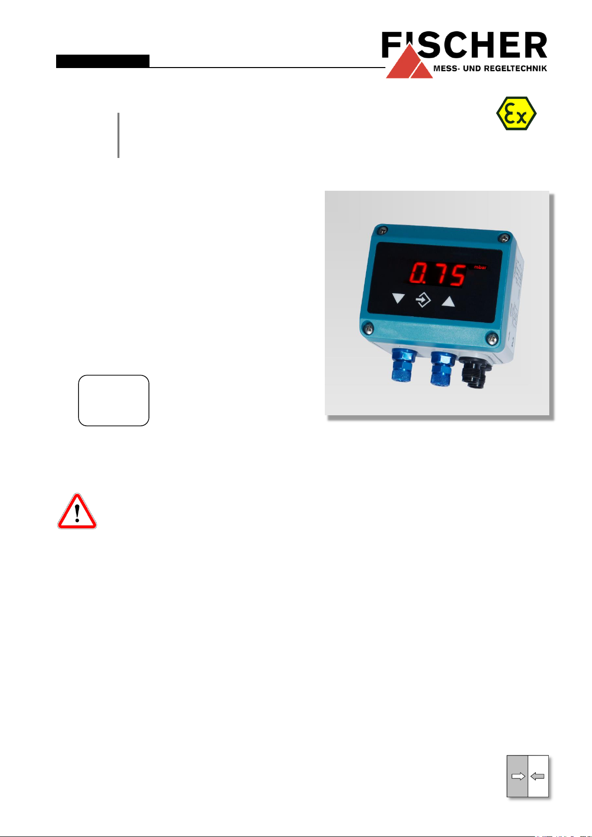
Digital differential pressure switch / transmitter
DE45##00###K0#M#R####
Gas explosion protection zone 2
II 3G
Ex nA IIC T4
-10°C ≤ T
amb
≤ 60°C
Table of Content
1 Safety guidelines
2 Intended use
3 Description of the product and functional description
4 Installation and assembly
5 Commissioning
6 Maintenance
7 Transport
8 Service
9 Accessories
10 Disposal
11 Technical data
12 Dimensional drawings
13 Order Codes
14 Manufacturer's Declarations and Certificates
1 Safety guidelines
1.1 General Information
This operating manual contains instructions fundamental to the installation, operation and maintenance of the instru-
ment that must be observed unconditionally. It must be read by the assembler, operator
and the specialized personnel in charge of the device before it is installed and put into operation.
This operating manual is part of the product and
therefore must be kept close to the device in a
place that is easily accessible for the responsible
personnel.
The following sections, in particular the instructions
about assembly, commissioning and maintenance,
contain important safety information, nonobservance of which could lead to risks to people,
animals, the environment and objects.
1.2 Personnel Qualification
*09005069* DB_BA_EN_DE45_R Rev.B 09/16
The instrument may only be installed and commissioned by specialized personnel familiar with the installation, commissioning and operation of this
product.
Specialized personnel are persons who can assess
the work they have been assigned and recognize
potential dangers by virtue of their specialized training, their skills and experience and their knowledge
of the pertinent standards.
For explosion-proof models the specialized personnel must have received special training or instruction or be authorized to work with explosion-proof
instruments in explosion hazard areas.
1.3 Risks due to Non-Observance of Safety Instructions
Non-observance of these safety instructions, the intended use of the device or the limit values given in
the technical specifications can be hazardous or
cause harm to persons, the environment or the
plant itself.
Claims for damages from the manufacturer are excluded in this case.
Page 2

WARNING!
… indicates a potentially dangerous
situation, non-observance of which
could endanger persons, animals, the
environment or objects.
INFORMATION!
… highlights important information for
efficient and fault-free operation.
TIP!
… highlights recommendations that
may be useful but which are not necessarily required in specific situations.
1.4 Safety Instructions for the Operating Company and the Operator
The safety instructions on correct operation of the
device shall be observed. The operating company
must make them available to the installation,
maintenance, inspection and operating personnel.
Dangers arising from electrical components, energy
discharged by the medium, escaping medium and
incorrect installation of the instrument must be eliminated. For more information, please refer to the
applicable national and international regulations.
In Germany these are the DIN EN, UVV and, in industry-specific cases, the DVGW-, Ex-, GL-, etc.,
the VDE guidelines and the regulations of the local
power utility companies.
The instrument must be decommissioned and secured against inadvertent re-operation if a situation
arises in which it must be assumed that safe operation is no longer possible. Reasons for this assumption could be:
• evident damage to the instrument,
• failure of the electrical circuits,
1.7 Safe working practices for maintenance and installation work
The safety instructions given in this operating manual, any nationally applicable regulations on accident prevention and any of the operating company's
internal work, operating and safety guidelines must
be observed.
The operating company is responsible for ensuring
that all required maintenance, inspection and installation work is carried out by qualified specialized
personnel.
1.8 Explanation of the symbols
• long storage in temperatures over 70°C,
• considerable strain due to transport.
• Repairs may be carried out by the
manufacturer only.
A professional single conformity inspection as per
DIN EN 61010, section 1, must be carried out before the device can be re-commissioned. This inspection must be performed at the manufacturer's
location. Correct transport and storage of the device
is assumed.
The following sections, in particular the instructions
about assembly, commissioning and maintenance,
contain important safety information, nonobservance of which could lead to risks to people,
animals, the environment and objects.
1.5 Unauthorised Modification
Modifications of or other technical alterations to the
instrument by the customer are not permitted. This
also applies to replacement parts. Any modifications / alterations required shall be carried out by
Fischer Mess- und Regeltechnik GmbH only.
2 Intended use
Display and switching device for differential pressure of gaseous media. The instrument is to be exclusively used for the applications agreed between
the manufacturer and user.
Explosion hazard area classification
The differential pressure switch / transmitter DE45
is suitable for use in explosive areas "zone 2" as an
electrical device".
Designation as per guideline 94/9/EC
II 3G Ex nA IIC T4
-10°C ≤ T
≤ 60°C
amb
1.6 Inadmissible Modes of Operation
The operational safety of this device can only be
guaranteed if it is used as intended. The device
model must be suitable for the medium used in the
system. The limit values given in the technical data
may not be exceeded.
Page 3
3 Description of the product and func-
tional description
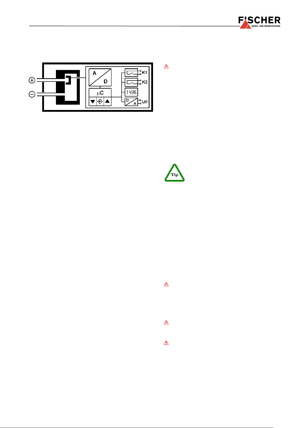
3.1 Function diagram
3.2 Design and mode of operation
The device is based on a piezo-resistive sensor element that is suitable for measuring overpressure,
underpressure and differential pressure. The pressures to be compared directly act on a silicon diaphragm equipped with piezo-resistive resistors. In
case of equal pressure, the measuring diaphragm is
in its idle state. In case of pressure difference, the
force acting on the measuring membrane causes it
to be moved towards the side of the lower pressure.
This movement of the diaphragm induces a change
of resistance, which is evaluated by the device's
electronics and transformed into signals on the display, switch contacts and an output signal.
4 Installation and assembly
The unit is designed for mounting on flat assembly
plates. For screw connection to the assembly plate,
the device features four assembly bores on its
back, which can be used for 3.5 mm tapping
screws.
Optionally, the device can be delivered with a wallmounting plate (see 13, order code).
At the factory, the device is calibrated for vertical
installation, but the installation position is arbitrary.
For installation positions deviating from the vertical,
the zero-point signal can be corrected by the integrated zero-point adjuster (see 5.3.2).
The enclosure protection type IP 65 is only guaranteed, if a suitable power supply cable is used (see
accessories).
4.1 Process connection
• By authorized and qualified specialized person-
nel only.
• Check that the pressure connections do not
leak before commissioning.
• Maximum pressures shall be observed.
Do not blow into the pressure connections!
The pressure connections are marked with (+) and
(-) symbols on the device. For differential pressure
measurements, the higher pressure is connected to
the (+) side and the lower pressure to the (-) side of
the device.
The pressure measuring lines must be installed on
a gradient so that no air pockets e.g. for liquid
measurements, water pockets or for gas measurements can be created. If the required incline is not
reached, water and/or air filters need to be installed
at suitable points.
The pressure sensing lines need to be kept as short
as possible and installed without sharp bends to
avoid interfering delay times.
If the pressure sensing lines are already
pressurised at the time of commissioning, zero-point control and adjustment
cannot be performed. In such cases, the
device should be only connected to the mains without the pressure sensing lines.
4.2 Electronic connection
• By authorized and qualified specialized person-
nel only.
• The electrical connection of the device shall be
performed according to relevant VDE and local
electricity board regulations.
• Disconnect the system from the mains before
connecting the device.
Refer to the technical data for the recommended
power supply.
To guarantee safe operation of the device, the
supply circuit must satisfy the requirements for
zone 2, category 3, and the local applicable
regulations and guidelines for the installation
and operation of electrical systems in explosion
hazard areas (e.g. EN 60079-14).
The supply voltage (24 V DC/AC) may not ex-
ceed 32V DC/AC. The supply circuit must be
protected by a 200mAT fuse.
• The pipes need to be depressurized when the
instrument is being connected.
• Appropriate steps must be taken to protect the
device from pressure surges.
• Check the suitability of the device for the media
to be measured.
The device may be configured with the
EU03.F300 configuring adaptor outside of the
explosion hazard areas only (i.e. not in zone 2).
Page 4
ÿ
Page down menu
Reduce value
û
Enter key
þ
Page up menu
Increase value
1
bridged internally
Signal -Sig
Power supply -
U
b
Signal +Sig
n.c.
Power supply
+U
b
SP1 SP2 SP2 SP1
p
Delivery
Analysis
e.g. SPS
Reception
+ - -Sig /
+Ub
+Sig
-Ub
Delivery
230V ~
L
N
+Ub
-Ub
Switching output 1
Switching output 2
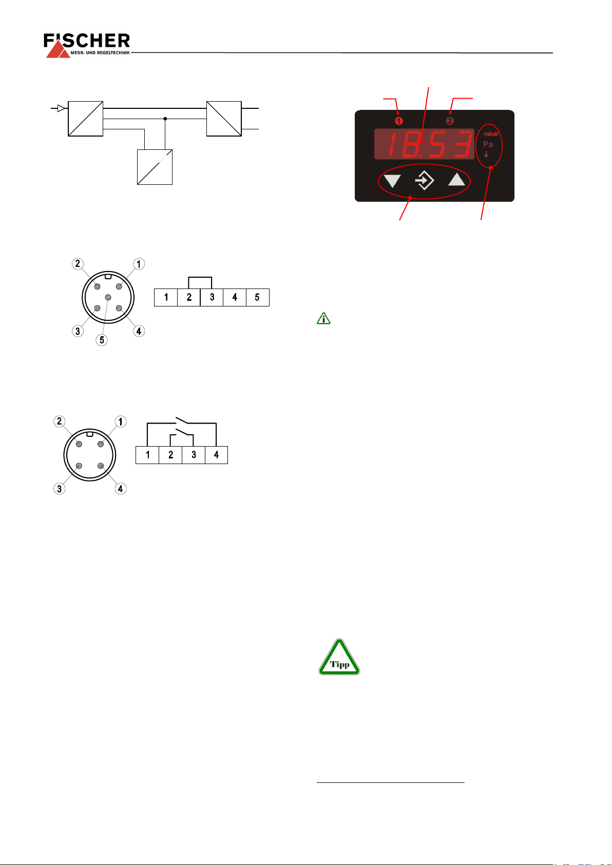
3.5 character LED display
Operating keys
Measuring unit
3 conductor circuit
Connector 1: Power supply and output signal
•
Connector 2: Switching outputs
5.1 Display
• The 3.5 digit LCD display represents the current
differential pressure in normal mode.
• The selected measuring unit is illuminated on
the right of the display.
The units shown in the picture may vary from
the actual model.
• Two light diodes and above the display in-
dicate the status of the switching outputs. As
soon as the switch is closed, the respective
LED shines.
The nominal supply voltage and the permissible
range can be found in the technical data.
The admissible load / resistance for the signal output is stated in the technical data.
The connection "Signal ground“(-Sig) is connected
internally to the supply ground. It only serves as the
ground connection for the output signal. This means
that the output signal is free of interference levels
on the power supply lines.
5 Commissioning
All electrical supply, operating and measuring lines,
and the pressure connections must have been correctly installed before commissioning. All supply
lines are arranged so that there are no mechanical
forces acting on the device.
Check that the pressure connections do not leak
before commissioning.
5.2 Operating keys
The operating keys have the following function:
5.3 Configuration
For commissioning there is a multitude of setting
options for optimum adaptation of the device to the
measuring point and task at hand. This section covers these options step by step.
Depending on the device model 1 some menu items
may not be available. For example, all characteristic
curve functions are faded out in the menu if the device does not have a signal output.
It is possible to completely configure the
device using a PC adapter at the PC.
Here all parameters are directly visible
and accessible. Also, the entire configuration can be loaded, saved and documented as a
printout. For more information about this program,
please refer to the program documentation (cf. Accessories).
with regard to the transmitter signal, voltage output, current
output, etc.
Page 5
2
3
5.3.1 General points
Connect the device to the power supply and ensure
that it is not under any pressure (if necessary, disconnect any pressure lines).
Proceed as follows to set a parameter:
• Press the enter key û to switch to the menu.
ESc will appear on the display.
• Use the arrow keys ÿ þ to select a parameter
from the list.
• Press the enter key û to call up the parameter.
• Use the arrow keys ÿ þ to set the required val-
ue.
• Press the enter key û to save the value.
After setting all parameters, leave the menu as follows:2
• Use the arrow keys ÿ þ to set the ESc parame-
ter. You will find these at the start and also at
the end of the list of parameters.
• Press the enter key û to leave to the menu.
5.3.2 Selecting the pressure unit
First select the pressure measuring unit. The unit
that is currently valid is illuminated to the right of the
number displays. Press the middle key û to make
the setting and then search for the parameter EIN
using the right-hand key þ. Press û again an then
change the displayed value using þ or ÿ.
1 = top
2 = middle
3 = bottom
Once the value has been selected, save it with û
and EIN will appear again in the display.
Then leave the setting mode. Press ÿ until Esc and
the û appear. The current measured pressure is
shown again. The correct pressure unit is now illuminated to the right of this.
The display can only show up to ±1999.
Therefore in some cases it may not be
possible to select all stated pressure
units.
5.3.3 Zero point control and adjustment
Ensure that the device is not under any pressure (if
necessary, disconnect any pressure lines).
If the device does precisely indicate zero at this
point of time, parameter OF1 enables you to adjust
the measuring value exactly to zero. To do so, you
All set parameter values are only valid once you leave the
menu via the ESC parameter.
have to set the measuring value indicated below OF1
to zero.
After zero-point adjustment, the pressure sensing
lines can be reconnected.
5.3.4 Damping and zero-point stabilising
If there are unsteady pressure readings at this point
of time or during operation, you can use parameters
DAM and NP to stabilise the reading (and the output
signal).
The parameter DAM functions like a capillary throttle.
However, it only acts on the display, output signal
and switch points (if these exist) but not on the
measuring cell itself. With this parameter, the response time can be set to pressure jumps. The value range comprises 0.0 s to 100.0 s.
But with maximum attenuation, it will
take more than 2 minutes for the reading to also reach zero after a pressure
jump from nominal pressure (100 %) to
zero!
In many cases, unsteady readings are not a problem during normal operating mode, but this is not
true for the idle state, i.e. if zero (differential) pressure is expected.
In such situations, parameter NP can be applied. Its
value defines a measuring value range around zero. Within this range, the measuring value is set to
zero.
Example:
A value of 0.08 mbar 3 is entered for NP. In this
case all pressures within the range of -0.08
mbar to +0.08 mbar are set to zero. The reading will only not indicate zero anymore if the
pressure exceeds these limits. However the
pressure value and display do not correspond
to one hundred percent. The measuring pressure and reading match again when the double
value, in this case 0.16 mbar, is reached again.
5.3.5 Setting the output signal
The transmitter output signal primarily depends on
the sensed pressure. However, you have the option
of adjusting the output signal to a large extent to
suit your requirements.
However the basic measuring range
(indicated on the type label) and the
type of output signal (voltage / current)
are not variable.
Parameters MA (start of measuring range) and ME
(end of measuring range) define the two pressures
between which the output signal can generally
change. Both values are adjustable across the entire basic measuring range. The set values always
0.08 mbar ≙ 8 Pa
Page 6
F
0
linear characteristic curve (standard)
1
square rooted characteristic curve
2
flat cylindrical tank
3...30
Support point table with 3 to 30 pairs of values
refer to pressure (in the relevant measuring unit)
and are converted when the measuring unit is
changed.
The assigned signal values for MA and ME are invariable (type label, e.g. 0…10 V or 4…20 mA).
If MA is smaller than ME this is referred ´to a rising
characteristic curve. The output signal grows as the
pressure increases.
If ME is smaller than MA, this is a decreasing characteristic curve and the output signal decreases with
the falling pressure.
The difference between values MA and ME must at
least be 25 % of the basic measuring range. The
software does not allow any larger spreads. If the
range information is stated wrongly, you cannot
leave the menu.
Example:
The following must apply for a basic measuring
range of 400 Pa: MA – ME 100 Pa.
5.3.6 Output signal limits (Namur)
Regardless of the pressure, the three parameters
oG1, oG2 and oEr define the limit values for output
currents or voltages that may not be undercut or
exceeded.
These limit values have priority over the
range defined by the MA and ME. They
primarily serve to prevent error messages in downstream systems caused by a
brief overstepping of measuring ranges.
The parameter oG1 defines the limit value for the
minimum output signal. The output signal may not
undercut this value. Usually, this parameter is only
recommended for devices with an output signal of
4…20 mA because in these devices, a value below
3.8 mA is often assessed as an error signal.
output is directly changed. You operate the device
then as a transducer and can simply check the further signal processing.
5.3.7 Characteristic curve function F
In some applications, measuring pressure is an indirect unit for the actual measuring variable. Flow
measurements via a panel or determining the filling
level by means of hydrostatic pressure measurements are two typical examples of this. In these
cases, you might want to change the output signal
of the transmitter to a non-linear characteristic
curve so that the following analysis receives a signal that is linear-proportional to the actual measuring variable (e.g. volume in m³ or volume flow cm³/s
etc.)
The parameter F allows you to select between the
following variants:
Whenever you change the value from F, the program creates a new table. All previous values in the
table are rejected and replaced with new linear entries.
The tables of type F = 0 to F = 2 are not visible. Internal values are used here to calculate the table.
These values are invariable.
For F = 3...30 you can only influence the 1..28 intermediate values (cf. 5.3.8) You only have access
to the start and end values via the MA and ME parameters.
When the parameters MA and ME are
changed the table is deleted and F = 0 is
set.
The parameter OG2 defines the limit value for the
maximum output signal. The output signal may not
exceed this value. This parameter can be used for
all outputs (voltage and current) to limit the maximum value of e.g. 10.2 V.
The parameter oer defines the value for the error
signal. The value defined via the oEr is issued as an
output signal, if the device detects an internal error
and can no longer work correctly. However, the device is not able to recognise all possible errors and
defects.
If you set oG1 = OG2 = 0, the output signal will no
longer be checked for limits.
If you set oG1 to the maximum value (11
V or 21 mA), you can use OG2 to adjust
the output signal independent of the
pressure from zero to the maximum
value. You do not need to leave the menu item, the
At the start of the measuring range (MA) 0% of the
output signal (e.g. 0 mA) is issued.
At the end of the measuring range (ME) 100% of the
output signal (e.g. 20 mA) is issued.
5.3.8 Menu jump LIN
If the value of F is greater than or equal to 3, there
is a submenu LIn. here you can access all table values apart from the table start (MA) and end (ME).
This submenu has its own entry and exit point that
is shown with End. The table is only saved if you return to the main menu at this point, i.e. if you
change to the parameter LIN again via the key û.
If the table is not structured correctly, an error message Err will appear here and you cannot quit the
submenu.
Page 7

4
The table comprises 3…30 pairs of values. In the
case of a device with a power output, the first pair
of values is {I01|P01} 4. The first value I01 defines
the output signal. The second value P01 determines the pressure at which the output signal is issued.
Followed by the pairs of values {I02|P02} ... {I30|P30}.
Entering or changing values in the table via the
membrane keypad is tiresome and prone to errors.
This is only intended as an emergency solution in
case access to the PC adapter is not possible.
The table is correct if the following applies for all
signal values: The value is larger than the previous
value. Either larger (rising characteristic curve) or
smaller (falling characteristic curve) apply to the
pressure values accordingly. No transition from rising to falling characteristic curves or vice versa is
allowed.
5.3.9 Switch points
The two switch outputs are configured by four
parameters respectively.
The function of the switching output is determined by the parameters R1A, R1E, R1D and R1F.
The function of the switching output is determined by the parameters R2A, R2E, R2D and R2F.
tact, if the value = 2, the switch out works as a NC
contact.
5.3.10 Password
The last menu item -P- is used to enter a password.
A value between 001 and 999 can be selected for
the password. The value 000 cancels the password
function.
If a password has been issued, the text PAS appears
after ESc and û, and you need to enter the correct
value using û and þ,ÿ. You will only arrive at all
other menu items after doing this. In the event of an
error, the display will jump back to the start of the
menu ESc.
If the password is forgotten, it can only
be reset by the manufacturer or overwritten via the PC adapter.
5.3.11 Display options
The parameter D0 enables the reading to settle if
the measuring value fluctuates heavily. This filter
function is similar to the dAM function, but only impacts on the reading not on the output signal.
At D0 = -1 only the switchpoint LEDs are controlled.
At D0 = -2 these are switched off.
5.3.12 Reset to default
R1A defines the switch-off point; R1E defines the
switch-on point from of switch output 1. The values
are set in the valid measuring unit (shown on the
right).
Together, the two parameters R1A and R1E determine
the switch function of switch output 1:
If R1A is smaller than R1E, the output switches on, if
the measured value exceeds R1E. It is only switched
off again if the measured value R1A is undercut (hys-
teresis function).
If R1A = R1E, the output switches on if the measured
value exceeds R1E and off if the measured value undercuts R1A.
If R1A is larger than R1E, the output switches on, if R1E
< Measured value < R1A applies (window function).
Both parameters can be set independently over the
entire range.
If the measuring unit is switched over, the switching
points are converted accordingly. Rounding errors
may cause deviations in the last position.
R1D allows the reaction of the switch output 1 to be
delayed by between 0.0 and 100.0 s. This value
applies equally for switching on and off.
The function res allows all settings to be reset to
the default settings. The default values can only be
defined via a PC interface.
5.3.13 Free unit
If the device is designed for a "free" third unit
(membrane symbol: ), the display can be scaled
infinitely using the parameters MAF, MEF and dPF.
The measuring range defined by the parameters MA
and ME is converted to MAF and MEF. This also takes
into account the table function ( F ). The value of dPF
determines the position of a decimal point.
R1F reverse the function of the switch output. If the
value = 1, the switch output works as an NO con-
At a voltage output {u01|P01} ... {u30|P30}.
Page 8

PAS
Enter password
(only appears if the password is active), value range 000...999
000 = deactivated
DAM
Attenuation
(Jump response time T90),
value range 0.0..100.0s
d0
Display attenuation
Value range -2...0...100.
-2 = Display off, LED Switch point off
-1 = Display off, LED Switch point on
0 = Display on, LED Switch point on
1...100 Display attenuation
R1A
Switch-off point
From switching output
R1E
Switch-on point
From switching output
R1D
Switching delay
from switch output •
Value range 0.0 to 100.0s. This value
applies equally for switching on and off.
R1F
Switching function
From switching output
Values range 1,2
1 = Switching output as NO contact,
2 = Switching output as NC contact
R2A
Switch-off point
From switching output
R2E
Switch-on point
From switching output
R2D
Switching delay
from switching output
Value range 0.0 to 100.0s. This value
applies equally for switching on and off.
R2F
Switching function
From switching output
Values range 1,2
1 = Switching output as NO contact,
2 = Switching output as NC contact
ON
Measuring range unit
Value range 1,2,3
The selection is illuminated on the right
of the reading. Not all basic measuring
ranges allow free switchover. The respective unit size can only be selected
if the basic measuring range of the device can be shown sensibly.
MA
Start of measuring range
The measuring value is set in that the
output signal is minimal.
(e.g.: 0V, 0mA or 4mA).
ME
End of measuring range
The measuring value is set in that the
output signal is maximum.
(e.g.: 10V, or 20mA).
np
Zero-point stabilising
Value range 0 to ⅓ of the basic measuring range. The value acts symmetrically around real zero.
dpf
Free unit
Decimal point position
maf
Free unit
Start of measuring range (display)
mef
Free unit
End of measuring range (display)
Of1
Offset correction measuring input 1
Value range -⅓ FS...0... +⅓ FS
F
Characteristic curve function
Value range 0...30
0 = linear,
1 = square rooted,
2 = flat cylindrical tank
3..30 = Table
lIn
Menu jump
Submenu table processing
If F < 3 this menu item is faded out.
oG1
Limit value
Minimum output signal
OG2
Limit value
Maximum output signal
OEr
Error signal
(Output signal in error case)
5.4 Parameter overview
After switching on the device, it will briefly indicate
the software version number and then enters the
normal operating mode. By using the middle û key
on the membrane keypad you can access the parameter menu. The reading now shows the text ESc.
By using the right þ key, you can choose the parameters from the following list one by one:
Note:
Depending on the device model, individual parameters may not be available if
the device does not have this feature.
Page 9

res
Reset
all parameters to standard values
(specification of the standard values
per PC)
-P-
Password setting
Value range 000 to 999
Value 000 does not hold password protection.
6 Maintenance
The device is maintenance-free.
We recommend regular inspections to guarantee
reliable operation and a long life cycle, such as:
• Checking the reading.
7 Transport
The device must not be exposed to mechanical
shocks. It shall be transported only in packaging
specifically intended for transport.
8 Service
All damaged or faulty devices shall be directly sent
to our repair department. Please coordinate the return of any device with our sales department.
Process media residues in and
on dismantled instruments can be a
hazard to people, animals and the envi-
ronment. Take adequate preventive
measures. If required the devices shall be thoroughly cleaned.
• Checking the switching function in combination
with downstream components.
• Checking the leak-tightness of the pressure
connection lines.
• Checking the electrical connection (cable clamp
connections).
The exact test cycles shall be adapted to the operating and ambient conditions. The operating manuals of any other connected device components shall
also be observed.
9 Accessories
• Set of cables with M12 connectors (please en-
quire)
• PC adapter with type EU03.F300 software
10 Disposal
For the sake of the environment ....
Please help to protect our environment and dispose of or recycle used
devices as required by the applicable
regulations.
Page 10

+ ranges (0 … )
+/- ranges
Measuring
ranges
mbar
4 6 10
16
25
40
60
100
160
250
2.5 4 6
10
16
25
40
60
100
Pa
400
600
1000
1600
250
400
600
100
1600
kPa
0.4
0.6
1.0
1.6
2.5
4.0
6.0
10.0
16.0
25.0
0.25
0.4
0.6
1.0
1.6
2.5
4.0
6.0
10.0
Static operat-
ing pressure
max.
mbar
50
100
250
500
1500
50
100
250
500
Bursting pres-
sure
mbar
150
300
750
1500
3000
150
300
750
1500
Characteristic
curve deviation
°)
max.
%FS
1.0 1.0
typ.
%FS
0.5 0.5
Tk span°°)
max.
%FS/10K
1.0
0.3 0.4
1.0
0.5
0.3
typ.
%FS/10K
0.3 0.3
Tk zeropoint
°°)
max.
%FS/10K
1.0
0.4 1.0
0.5
0.4
typ.
%FS/10K
0.2 0.2
General points
Admissible ambient temperature
-10°C ≤ Tamb ≤ 60°C
Admissible media temperature
-10 ... 60°C
Admissible storage temperature
-20 ... 70°C Enclosure protection class
IP 65 acc. to DIN EN 60529
Electrical data
Nominal voltage
24V AC/DC
Admissible operating voltage Ub
12 ... 32V AC/DC
A CE-compliant power supply unit with a 200 mAT fuse only may be used as a power supply.
Electrical connection type
Three-wire
Output signal
0 ... 20mA, 4 ... 20mA AC/DC
0 ... 10V DC
Admissible apparent ohmic
resistance
R
L
≤ (U
b
- 4 V) / 0,02A (for Ub ≤ 26V)
RL ≤ 1100 Ω (for Ub > 26V)
RL ≥ 2 KΩ (for Ub ≥ 15V),
RL ≥ 10 KΩ (for Ub = 12 …15V)
Power consumption
approx. 2 W / VA
Display
3.5 character LED
Switch contacts
2 potential-free semiconductor switches (MOSFET., 1-pin, NO/NC programmable)
U
max
I
max
RON
P
max
3…32 V DC/AC
0,25 A
≤ 4 Ω
8 W / VA
Connections
Process connection
Hose screw connections made of Al, 6/4 mm or 8/6 mm
electr. connection
2 x round plug connector M12
Connector 1 for supply and analogue output signal (5-pole, male)
Connector 2 for switch contacts (4-pole, male)
Materials
Casing
Polyamide PA 6.6
Media-contacting material
Silicon, PVC, aluminium, brass
Assembly
Bore-holes on the reverse side for attachment of the assembly panels
Panel mounting set
Wall mounting by means of assembly plate
Markings
II 3G Ex nA IIC T4
11 Technical data
°: Characteristic curve deviation (non-linearity and hysteresis) at 25°C, basic measuring range (linear characteristic curve, not spread)
°°: :with reference to the basic measuring range (not spread); compensation range 0..60°C.
Page 11

Settings
Attenuation
0.0 ... 100,0 s (jump response time 10 / 90 %) for signal output; separately also for display
Switching output 1 / 2
Switch-off point, switch-on point, response time (0...100s), function (NC / NO contact)
Measuring range unit
mbar / Pa / "fee unit", starting value, end value and decimal point for "free unit"
Zero-point stabilising
0 ... 1/3 of the basic measuring range (1)
Output signal
User-definable within the basic measuring range (2)
Zero point correction
± 1/3 of the basic measuring range (3)
Implementation of characteristic curve
linear, square rooted, flat cyl. tank, table with 3...30 support points
Password
001 ... 999 (000 = no password protection)
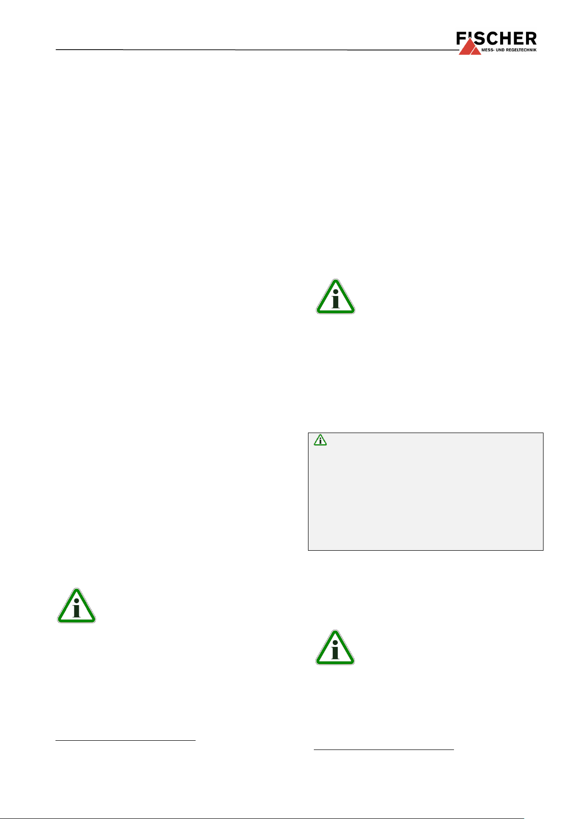
Panel mounting
Wall mounting plate
(optional)
Rear view
Without wall mounting
Hose screw connection
for 6 or 8 mm hose
Connector 1
Connector 2
Bore-holes for
tapping screws Ø 3.5 mm
M12 connector
(all dimensions in mm unless otherwise specified)
Wall thickness
11.1 Programming
Programming is carried out via the membrane keypad and menu navigation; can be locked with a password
Comments:
(1): Measuring values (around zero) are set to zero (e.g. to supress seepage)
(2): Maximum effective spread 4:1. Only the output signal is influenced. This in turn enables a decreasing characteristic curve, if the
start of the measuring range > end of the measuring range.
(3): Zero point correction for compensation of various installation positions.
12 Dimensional drawings
Page 12

Digital differential pressure switch / transmitter,
with 3 ½-digit LED display
Type DE45
0 0 K
6 M
R####
Measuring ranges
0 … 4 mbar ........................................................................ >
5 2 0 … 6 mbar ........................................................................ >
5 3
0 … 10 mbar ........................................................................ >
5 4
0 … 16 mbar ........................................................................ >
5 5 0 … 25 mbar ........................................................................ >
5 6
0 … 40 mbar ........................................................................ >
5 7
0 … 60 mbar ........................................................................ >
5 8 0 … 100 mbar ........................................................................ >
5 9
0 … 160 mbar ........................................................................ >
6 0
0 … 250 mbar ........................................................................ >
8 2 -2.5 … +2.5 mbar ........................................................................ >
A 6
-4 … +4 mbar ........................................................................ >
A 7 -6 … +6 mbar ........................................................................ >
A 8
-10 … +10 mbar ........................................................................ >
A 9
-16 … +16 mbar ........................................................................ >
B 1 -25 … +25 mbar ........................................................................ >
B 2
-40 … +40 mbar ........................................................................ >
C 5
-60 … +60 mbar ........................................................................ >
B 3 -100 … +100 mbar ........................................................................ >
B 4
0 … 400 Pa ........................................................................... >
D 7
0 … 500 Pa ........................................................................... >
J 7 0 … 600 Pa ........................................................................... >
D 8
0 … 1000 Pa ........................................................................... >
D 9
0 … 1600 Pa ........................................................................... >
E 1
-250 … +250 Pa ........................................................................... >
L 6
0 … 1 kPa.......................................................................... >
N 1
0 … 1,6 kPa.......................................................................... >
N 2 0 … 2,5 kPa.......................................................................... >
N 3
0 … 4 kPa.......................................................................... >
N 4
0 … 6 kPa.......................................................................... >
N 5 0 … 10 kPa.......................................................................... >
E 5
0 … 16 kPa.......................................................................... >
E 6
0 … 25 kPa.......................................................................... >
E 7 -1 … +1 kPa.......................................................................... >
L 8
-1,6 … +1,6 kPa.......................................................................... >
L 9
-2,5 … +2,5 kPa.......................................................................... >
M 6 -4 … +4 kPa.......................................................................... >
M 7
-6 … +6 kPa.......................................................................... >
M 8
Pressure connection
Aluminium screw connection for 6 / 4 mm hose ............................................................... >
4 0
Aluminium screw connection for 8 / 6 mm hose ............................................................... >
4 1
Electrical output signal
without analogue electrical output signal ................................................................................... >
0 0 – 20 mA 3-wire (STANDARD) ............................................................................................... >
A
0 – 10 V DC 3-wire (STANDARD) ............................................................................................ >
C
4 – 20 mA 3-wire (STANDARD) ............................................................................................... >
P
Operating voltage
24 V DC/AC (12 - 32 V DC/AC) ....................................................................................................... >
K
Measuring unit
Standard pressure units ......................................................................................................................... >
0
Measured value display / contact elements
3 1/2-digit-LED – 2 semiconductor switches ................................................................................................. >
6
Electrical connection
M12 plug connection ................................................................................................ .......................................... >
M
Assembly option
Standard (attachment boreholes on rear side) .......................................................................................................... >
0
Panel mounting set................................................................................................................................................... >
T
Wall mounting .......................................................................................................................................................... >
W
Customer-specific no.
Markings for use in zone 2 - risk by gases: II 3G Ex nA IIC T4........................................................................... >
R####
13 Order Codes
Page 13

Order Code
Designation
No. of
Poles
Usage
Length
06401993
Connection cable with M12 connector
4-pole
for switching outputs
2 m
06401994
Connection cable with M12 connector
4-pole
for switching outputs
5 m
06401995
Connection cable with M12 connector
5-pole
for supply / signal
2 m
06401996
Connection cable with M12 connector
5-pole
for supply / signal
5 m
EU03.F300
Adapter for parameterization via PC software
13.1 Accessories
Page 14

14 Manufacturer's Declarations and Certificates
Page 15

Page 16

Page 17

 Loading...