

Page 1
1 Safety Instructions
1.1 General
This manual contains detailed information about the product, and instructions for its installation, operation and maintenance. Operators
and other technical personnel responsible for the equipment must read this thoroughly before attempting to install or operate this
equipment. A copy of this manual must always be
kept accessible at the place of work for reference
by concerned personnel.
Chapter 1 (sections 1.2 through 1.7) contains general as well as specific safety instructions.
Chapters 2 through 10, covering topics ranging
from intended purpose of the equipment to its final disposal, also include important points relating to safety. Overlooking or ignoring any of these safety points can endanger humans and animals, and possibly cause damage to other equipment.
1.2 Personnel Qualification
Personnel responsible for installation, operation,
maintenance and inspection of this product must
have the qualifications, training and experience
necessary to carry out such work on this type of
equipment.
1.3 Risks of Disregarding Safety Instructions
Disregarding safety instructions, use of this product for purposes for which it is not intended,
and/or operation of this product outside the limits
specified for any of its technical parameters, can
result in harm to persons, the environment, or the
plant on which it is installed. Fischer Mess- und
Regeltechnik GmbH will not be responsible for
consequences in such circumstances.
1.4 Safety Instructions for Operators
Safety instructions for the proper use of this product must be followed. This information must be
available at all times to by personnel responsible
for installation, operation, maintenance and inspection of this product.
Adequate steps must be taken to prevent the
occurrence of hazardous conditions that can be
caused by electric energy and the convertible
energy of the process media. Such conditions
can, for example, be the result of improper
electrical or process connections.
Detailed information is available in relevant published norms (DIN EN, UVW in Germany; and
equivalents in other countries), industrial standards such as DVWG, EG-, GL-, VDE
guidelines, as well as regulations of the
local authorities ( e.g., EVUs in Germany).
# 09005136 26.03.2009 BA_D_DE38_D410
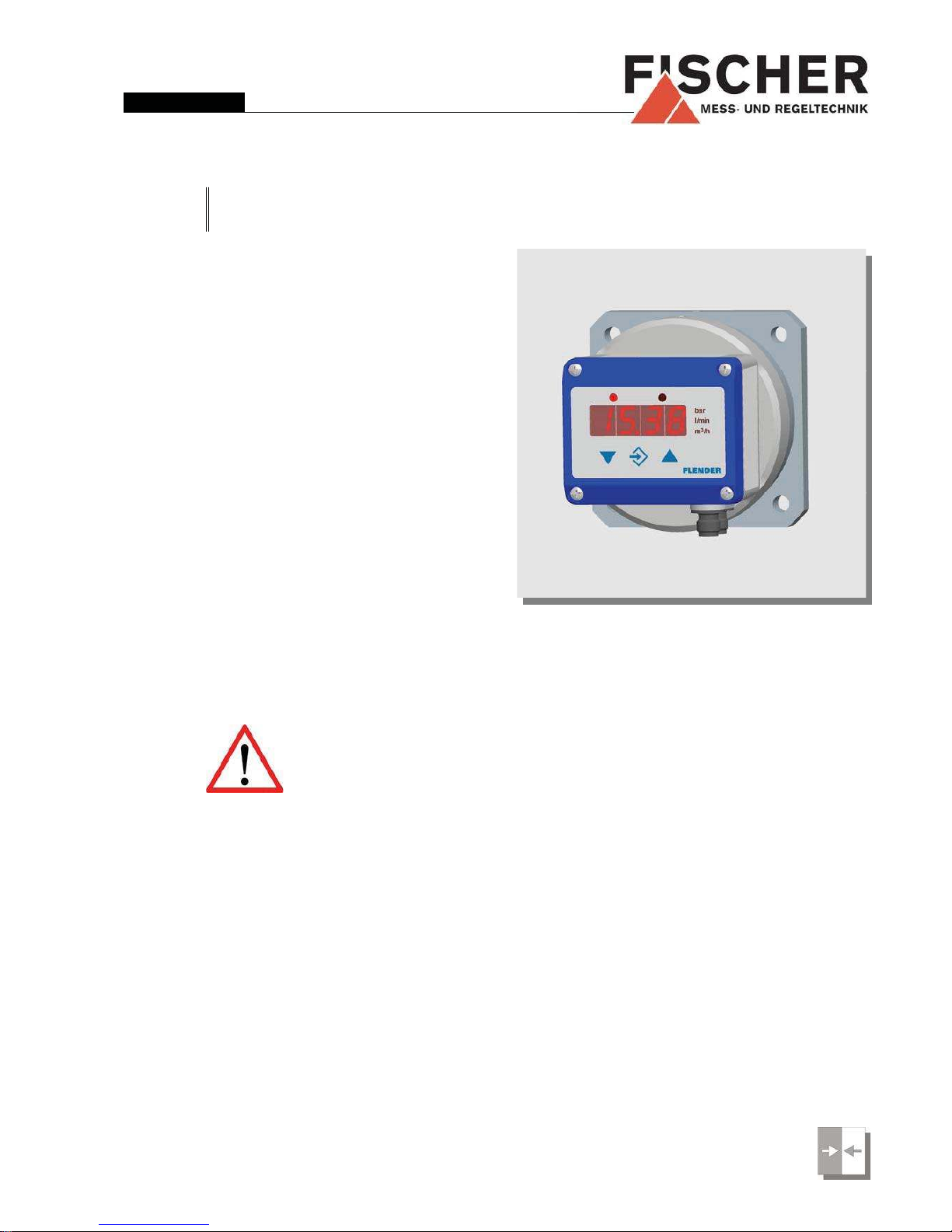
Ins tru ctio n M anu al
D E 3 8
D ig ita l D iffe re ntia l P re ss ure Tra nsm itte r / S witch
DE38D410
Inhalt
1 Safety Instructions .......................................1
2 Intended Applications...................................2
3 Product Description and Functions..............2
4 Installation....................................................2
5 Commissioning ............................................3
6 Maintenance ................................................8
7 Transport......................................................8
8 Service.........................................................8
9 Accessories..................................................8
10 Disposal.......................................................8
11 Specifications...............................................9
12 Dimensions ................................................11
13 CE-Certificate.............................................12
Contact: EK Engineering (www.ekeindia.com)
Email: india.eke@gmail.com
Mob: +91-9680966000
Page 2
1.5 Modifications Forbidden
Modification or other technical alteration of the product
is not permissible. This also applies to the use of unauthorized spare parts for repair / maintenance of the
product. Any modifications to this product, if and as necessary, should be done only by Fischer Mess- und Regeltechnik GmbH.
1.6 Operational Restrictions
The operational reliability of the product is guaranteed
only when used for intended purposes. The product
must be selected and configured for use specifically
with defined process media. The limiting values of operating parameters, as given in the product specification
sheet, must never be crossed.
1.7 Safety Considerations during Installation and Maintenance
The safety instructions given in this manual, existing national regulations relating to accident prevention, and
the internal safety rules and procedures of the user organization regarding safety during installation, operation
and servicing must all be followed meticulously.
It is the responsibility of the users to ensure that only
suitably qualified and experienced technical personnel
are used for installation, operation and servicing of this
equipment.
2 Intended Applications
The product includes the functions of sensing, signal
conversion, display, signal transmission, and limit detection of pressure / differential pressure of gases and
liquids. The product must be used only for applications
and under conditions specified by the manufacturer. In
case of uncertainties, the user should consult the manufacturer before installing and using the product.
3 Product Description and Functions
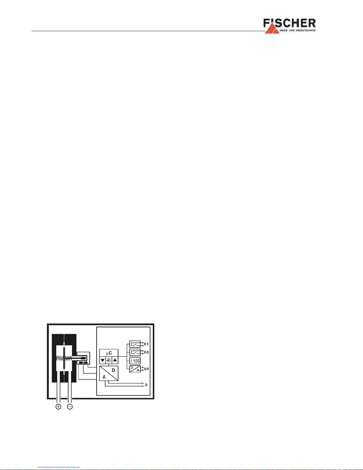
3.1 Block Schematic Diagram
3.2 Principles of Operation
The instrument uses a tough, robust sensing diaphragm, which is qualified for over-, low- and differential pressure measurings. The comparative pressures
work on a elastic bedded measuring diaphragm. The diaphragm is at zero position when pressures on either
side of the diaphragm are equal.Inequality of pressures
results in deflecting the diaphragm towards the lower
pressure side until a new equilibrium determined by the
spring power is reached. This deflection is transmitted
by a tappet to the center of a inductive travel sensor.
The integrated electronics analyzes the deflection and
converts it into display, switch contacts and output signal.
4 Installation
The instrument is intended for the assembly on the
base of the Flender circulatory- measurement.
At the installation of the upper part there should be paid
attention to the correct adjustment. The operator must
be able to regulate and read the instrument from a safe
place.
The sealing faces and the O- ring seals must not be damaged!
The instrument is adjustet for a vertical mounting position. Other positions aren't sensibel because of the clearness of reading the digital display.
If the instrument is intended for outdoor application, we
highly recommend using an ade-quate protective housing (or at least a big enough shelter) as permanent
protection against UV-radiation on the membrane keyboard and against exposure of the instrument to rain or
snow.
4.1 Process Connections
Ensure that process equipment and pressure lines
are at atmospheric pressure before making pressure
connections.
The instrument should be provided with suitable pro-
tection against pressure surges (e.g., snubber or
pulsation damper).
Ensure that the mechanical configuration and mate-
rials of construction of the instrument are compatible
with the process media.
Take account of the maximum pressure.
Carefully check the pressure-tightness of all pressu-
re connections before start-up.
4.2 Electrical Connections
Only qualified technicians authorized for this type of
work should undertake installation.
Electrical connections must comply with relevant in-
ternational, national and local regulations and norms
relating to electrical and instrumentation installations.
2
Contact: EK Engineering (www.ekeindia.com)
Email: india.eke@gmail.com
Mob: +91-9680966000
Page 3

Switch off electrical power to the plant before at-
tempting electrical installation work of any kind.
Make electrical connections to the transmitter
through a suitable energy-limiting safety device (isolation or zener barrier).
5 Commissioning
Power supply and signal cabling to the transmitter
must be correctly selected to meet operational requirements, and installed in a way that does not cause
physical stress to the instrument.
Pressure lines must have a downward gradient
throughout from the pressure instrument to the process vessel / pipe. This is to prevent formation of air
/ gas pockets (for liquid applications) and liquid plugs
(for air / gas applications). If this continuous downward gradient cannot be provided for any reason,
then suitable water and / or air separation devices
must be inserted into the pressure lines.
Pressure lines must be kept as short as possible and
must not have short bends to avoid measurement
errors induced by pressure line delays.
5.1 Pressure Connections
If the pressure transmitter is subjected to pressure
when it is started up, zero point checking and adjustment is not possible. In such cases, only electrical connections of the instrument should be made, but not the
pressure connections.
5.2 Display
The 3½ digit LED display normally indicates the current
differential pressure. The backlit symbols to the right of
the 3½ digit LED display indicate the unit of pressure
measurement. (Note: the units shown in the illustrations
of this document can be different from those of the actual instrument). The two LED lamps above the 3½ digit
LED display respectively indicate the status of the two
limit relays / solid-state switches
(LED on = relay
contacts closed / solid-state switch on).
While the instrument is in set-up mode, the 3½ digit
LED display either indicates the selected menu option
or a set-up parameter value. The instrument continues
its pressure monitoring functions even while it is in setup mode, except under either of two circumstances.
One is when the limit switching delay time is changed:
the existing delay must time out first. The other is when
the look-up table (for conversion of measured values) is
re-programmed (s. 5.3.7.). In these circumstances, the
output signal value and the limit relay/switch states are
frozen until the changes are finalized.
5.3 Set-up
The instrument has comprehensive set-up options by
means of which it can be optimized for any specific
measuring or control application. This section of the
document provides information and instructions about
each of the set-up parameters.
Depending on the instrument configuration ordered (e.g.: without transmitter signal
output / with voltage signal output / with
current signal output) some of the menu
options may not available. Some set-up
parameters may be consequentially excluded. For
example, if the instrument is ordered without a transmitter output, all signal conversion programming options
are omitted in the set-up menu (s. 5.3.6. Signal Conversion and Transfer Functions).
All instrument settings can be conveniently done from a
PC connected to the instrument through a serial interface adaptor. All set-up parameters can be viewed and
changed on the PC screen. Also, the entire instrument
set-up configuration can be loaded, stored on the PC's
hard disk drive, and printed out for plant / process documentation purposes. Further information about this PC
software is given in the software documentation.
5.3.1 Selecting the Unit of Pressure Measurement
Make the necessary electrical connections (signal, power supply) to the instrument. Its pressure sensor must
be pressure-free (i.e. vented to atmosphere; typically by
disconnecting the pressure line/s).
The current valid unit of measurement is indicated by
one of the back-lighted symbols to the right of the digital
display. To change the unit of measurement, first press
then search for parameter EEEEIIIINNNN using . Next press
again and select another unit of measurement using
or . Then presse again to store the selection, and
EEEEIIIINNNN will appear again in the digital display.
To exit the set-up mode, press
until EEEESSSScccc appears, and
then press
. The current pressure measured value is
indicated again, and the appropriate symbol of the unit
of measurement (to the right of the digital display) is
lighted.
The digital display is limited to a count of
±1999. Therefore, all the available units of
measurement may not be suitable for se-
lection for a given application.
3
Contact: EK Engineering (www.ekeindia.com)
Email: india.eke@gmail.com
Mob: +91-9680966000
Page 4
5.3.2 Zero Point Checking and Adjustment
If the instrument has been de-pressurized (vented to atmosphere) and does not indicate precisely zero, note
this non-zero value. Using the set-up parameter OOOOFFFF1111,
you can trim this offset to exactly zero. If the indicated
non-zero value is positive, this value must be entered
and stored as a negative offset value, and vice versa.
If the instrument was in use before zero
setting is done, values of set-up parameters OOOOFFFF1111 and nnnnPPPP would have been previously programmed. In this case, set
both values to zero, read the actual zero
offset, and then use this value for OOOOFFFF1111 for zero point correction, as described in the previous paragraph.
Note: The registered value is a pure number: no decimal point is indicated.
After correcting the zero offset, the pressure connections can be made again.
5.3.3 Damping and Zero Stabilization
If the media is subject to excessive pressure fluctuations, the displayed readings and the transmitter output
signal can be stabilized using the instrument's DDDDAAAAMMMM and
NNNNPPPP set-up parameters.
The set-up parameter DDDDAAAAMMMM has the effect of a pulsation
damper (on the displayed measurements, output signal
and limit detection, - not on the sensor itself!). It adds a
time-constant (averaging filter) in the user selectable
range of 0.0 to 100.0 secs. When the damping is set to
maximum, it took more than 2 minutes to reach the final
value for a full scale pressure jump.
In many cases fluctuating pressure readings do not
cause a problem, except when the plant / equipment is
at zero (differential) pressure condition and readings
fluctuate near about zero value. The set-up parameter
NNNNPPPP is meant to take of this. Its value defines the number
range across zero (similar to the zero offset correction
number), within which the measured value is forced to
zero. If a value of 8 is set for NNNNPPPP any pressure measurement in the range -0.08 to +0.08 bar (or -8 to +8 kPa)
displayed as zero. Only when the actual pressure is
outside this range will the display indicate a non-zero
value. The actual and displayed pressures will agree
starting from double the value of the NNNNPPPP setting (in the
given example: 0.16 bar or 16 kPa).
5.3.4 Output Signal Setting
The transmitter output signal depends primarily on the
measured pressure. However, this signal can be adapted to meet users' application requirements precisely.
The basic pressure range (as marked on the product
identification label) and the type of output signal (voltage or current) always remain unchanged for a particular
instrument unit.
The set-up parameters MMMMAAAA (measuring range starting
point) and MMMMEEEE (measuring range end point) specify the
pressure values between which the measurements are
expected to be. Both values can selected anywhere
within the specified measuring range of the instrument
(e.g., 400 kPa). This user-programmed pressure range
will correspond to the output signal (current or voltage)
range, which will be as specified on the product identification plate: i.e., 0 ... 10V or 4 ... 20 mA.
If MMMMAAAA is lower than MMMMEEEE, the signal is said to have a positive slope: i.e., the output signal increases as the pressu-
re increases. If MMMMEEEE is lower than MMMMAAAA, the output signal
has a negative slope: i.e., the output signal decreases
as the pressure increases.
The difference between the values of MMMMAAAA and MMMMEEEE must be
at least 25% of the specified measuring range of the instrument (100 kPa for 400 kPa instrument example
mentioned above). The software does not permit a
smaller pressure span to be entered (the instrument will
not allow storing of, nor exit from an invalid span).
Note: If you change MMMMAAAA and/or MMMMEEEE the lookup table (s .5.3.6., 5.3.7.) that existed up
to that instant is deleted!
5.3.5 Output Signal Limiting (Namur)
The three set-up parameters ooooGGGG1111, ooooGGGG2222 and ooooEEEErrrr specify
the limits of the signal output current or voltage that are
not to be exceeded, irrespective of the actual pressure.
These limit values have higher priority than the MMMMAAAA and
MMMMEEEE pressure span settings.
These settings serve mainly to prevent control systems
from interpreting brief pressure excursions outside the
measuring range as error / fault events. ooooGGGG1111 sets the
output signal minimum value, and is useful only for a
4 ... 20 mA current signal, because sometimes a value
below 3.8 mA is defined as a sensor fault condition. ooooGGGG22
22
sets the upper signal limit and is valid for either current
or voltage signal (e.g., voltage signal output can be limited at 10.2 V).
An instrument fault condition can be transmitted as an
output signal value set as parameter ooooEEEErrrr. However, it
should be understood that not all instrument fault and
error conditions can be detected and signaled by the
self-diagnostic functions of the instrument.
5.3.6 Signal Conversion and Transfer Functions
In certain cases other process variables are derived
from primary pressure measurement. Examples are
flow rate derived from differential pressure across an
orifice plate, and liquid level derived from hydrostatic
pressure of liquid measured at the bottom of the tank.
Such derivations often involve non-linear transfer functions, while it is necessary for the output signal to be linearly proportional to the derived variable (e.g. liquid volume in a tank in m³, or flow rate in cm/sec).
The set-up parameter FFFF allows the user to select the appropriate signal conversion function from those
4
Contact: EK Engineering (www.ekeindia.com)
Email: india.eke@gmail.com
Mob: +91-9680966000
Page 5

available:
FF
FF
= 0: Linear characteristic (default)
FFFF
= 1: Square root extraction
FF
FF
= 2: Horizontal cylindrical tank
FF
FF
= 3...30: Look-up table with 3 to 30 pairs of values
The tables generated by functions FFFF = 0, FFFF = 1 and
FF
FF
= 2 are not visible. For these functions, internal values are used for table computation. These values cannot be modified directly in the table by the user.
For all conversion functions, when the actual pressure
is equal to the MMMMAAAA value, the output signal will be at the
lowest end of its range (0 V, 0 mA or 4 mA). When the
actual pressure is equal to the MMMMEEEE value, the output signal will be at the highest end of its range (10 V or 20
mA). The user can enter only the 1...28 intermediate va-
lues of the look-up table function FFFF = 3....30. The para-
meters MMMMAAAA and MMMMEEEE relate to the start and end values of
the look-up table. A change in either of these parameter
values causes the conversion function to be re-set to
FF
FF
= 0.
Whenever the value of FFFF is changed, the
instrument internally generates a new
look-up table. All previous table values
are deleted and replaced by new linear progression values.
5.3.7 Look-up Table Programming (F = 3..30)
If the value of set-up parameter FFFF is selected equal to or
greater than 3, a sub-menu LLLLIIIInnnn is invoked. Through this
sub-menu all the required look-up table values can be
entered, except the first and last pairs of table values
(respectively corresponding to MMMMAAAA and MMMMEEEE). This submenu has its own entry and exit points, the latter being
the last of the value pairs to be entered. The table is
stored only when the user exits to the sub-menu prompt
LLLLIIIInnnn, by pressing
. If the table is not correctly entered,
the display will indicate EE
EE
rr
rr
rrrr, indicating an error condition. If this happens, it is not possible to exit this submenu mode until the error is corrected.
The table entries consist of 1 to 28 pairs of values. Values IIII00002222 through IIII22229999 (or uuuu00002222 through uuuu22229999) specify the
amplitude of the out the signal output, and the values
PPPP00002222 through PPPP22229999 are the corresponding pressure values.
Entering or changing table values through the instrument's membrane keyboard is a tedious and error-prone method. It should only be used as a stopgap method
when a PC and/or the PC interface module is not
available.
The table is accepted as correct if each output value is
larger than its preceding value. Pressure values can be
steadily increasing or steadily decreasing. However, a
transition from falling to rising pressure values is not
permitted; nor are pressure values allowed to turn back
along the same curve.
5.3.8 Limit Setting
The two limit switching outputs
(relay contacts or
solid-state switches) are each configured by four set-up
parameters:
Switching output 1 is configured by parameters RRRR1111AAAA,
RRRR1111EEEE, RRRR1111DDDD and RRRR1111FFFF .
Switching output 2 is configured by parameters RRRR2222AAAA,
RRRR2222EEEE, RRRR2222DDDD and RRRR2222FFFF.
The turn-on and turn-off points of switching output 1 are
defined respectively by parameters RRRR1111AAAA and RRRR1111EEEE. The va-
lues for these are set in the currently valid unit of measurement (indicated by the lighted symbol to the right of
the digital display).
The two parameters RRRR1111AAAA and RRRR1111EEEE together determine the
logic of switching output 1:
If RRRR1111AAAA is smaller than RRRR1111EEEE, the output turns on when the
measured value exceeds RRRR1111EEEE. It turns off again only
when the measured value falls below RRRR1111AAAA (hysteresis
function).
If RRRR1111AAAA and RRRR1111EEEE have the same value, there is no hysteresis: the switching output turns on when the measured
value exceeds RRRR1111AAAA / RRRR1111EEEE, and turns off again when the
measured value falls below RRRR1111AAAA / RRRR1111EEEE.
If RRRR1111AAAA is larger than RRRR1111EEEE, the switching output turns on
when the measured value falls between RRRR1111AAAA and RRRR1111EEEE:
i.e., when RRRR1111EEEE < measured value < RRRR1111AAAA (window limit
function).
Both parameters can be independently adjusted over
the full measuring range.
If the unit of measurement is changed, the switching
points are changed accordingly. In this event, rounding
error can cause a deviation in the least significant (rightmost) digit.
The value of the set-up parameter RRRR1111DDDD determines the
delay time for switching output 1, after the measured
value reaches the switching point. The delay value can
be selected in the range 0.0 to 100.0 secs. This value
applies equally to turn on and turn off.
The set-up parameter RRRR1111FFFF determines the action of the
switching output. If RRRR1111FFFF = 1, the switching output acts as
normally open (NO) contacts. If RRRR1111FFFF = 2, it acts as nor-
mally closed (NC) contacts.
5.3.9 Password
The last set-up parameter allows a password to be entered. A password value of 001 to 999 can be selected.
A value of 000 disables the password function.
If a password was set previously the digital display indicates PPPPAAAASSSS after EEEESSSScccc is displayed and
is pressed. The
password is then entered, by pressing and then , .
Only then will the set-up menu options be accessible. If
an incorrect password is entered, the display jumps
5
Contact: EK Engineering (www.ekeindia.com)
Email: india.eke@gmail.com
Mob: +91-9680966000
Page 6

back to beginning of the menu (i.e., EEEESSSScccc).
New Functions! (as of April 2008)
5.3.10 DD
DD0000
– Display options
This parameter allows smoothing the displayed values
in cases where they are frequently deviating. The filter
function is similar to the dd
ddAAAAMMMM
function, but acts only
upon the display, having no impact on the output signal.
Additionally the display can be turned off partially
(DD
DD0000
= -1, only the setpoint LEDs are driven) or comple-
tely (DD
DD0000
= -2).
5.3.11 rr
rreeeessss
– Reset to default values
This function will reset all parameters to default when
activated. Default values can be defined only by using
the PC interface.
5.3.12 MM
MMAAAAFFFF,,,, MMMMEEEEFFFF,,,, ddddPPPPFFFF
– Free Unit
If the device is configured to have a free third unit
(symbol:
) then the display can be scaled as desired
by using these three parameters.
The measuring range as defined by parameters MMMMAAAA and
MMMMEEEE is rescaled to MMMMAAAAFFFF and MMMMEEEEFFFF. If the table function (FFFF ) is
enabled, table values will be taken into account too.
The ddddPPPPFFFF value controls the position of the decimal point.
5.4 Overview of Set-up Parameters
When the instrument is turned on, it briefly displays the
software version number, and then switches automatically to normal operating mode. Pressing
causes the
set-up menu to be called up, indicated by EEEESSSScccc on the digital display. After that, by pressing repeatedly, each
of the set-up parameters is called up in sequence:
Note: Depending on the version of the instrument that was ordered, some of the individual
parameters might not be available.
PPPPAAAASS
SS
Password input (appears only if password
function has been enabled). Values: 001 to
999
DDDDAAAAMM
MM
Damping (time constant). Range of values
= 0.0 to 100.0 secs
DDDD00
00
Damping (display only), range of values
0..100. Additional: -1 = no digital value and
-2 = display turned off completely.
RRRR1111AA
AA
Switching output 1: turn-off point.
RRRR1111EE
EE
Switching output 1: turn-on point.
RRRR1111DD
DD
Switching output 1: delay. Range of values
= 0.0 to 100.0 sec. This values applies equally
for turn-on and turn-off delays.
RRRR1111FF
FF
Switching output 1 action. If RR
RR1111FFFF
= 1, acts as
NO contacts. If RR
RR1111FFFF
= 2, acts as NC contacts.
RRRR2222AA
AA
Switching output 2: turn-off point.
RRRR2222EE
EE
Switching output 2: turn-on point.
RRRR2222DD
DD
Switching output 2: delay. Range of values
= 0.0 to 100.0 sec. This values applies equally
for turn-on and turn-off delays.
RRRR2222FF
FF
Switching output 2 action. If RR
RR1111FFFF
= 1, acts as
NO contacts. If RR
RR1111FFFF
= 2, acts as NC contacts.
EEEEiiiiNN
NN
Unit of measurement. The selection is indicated by the lighted symbol to the right of the digital display. A particular unit can be selected
only if it can be meaningfully represented
within the basic measuring range of the instrument.
MMMMAA
AA
Measuring range start point. The value of the
measured variable corresponding with the minimum value of the output signal (0 V, 0 mA or
4 mA, depending on the instrument version).
MMMMEE
EE
Measuring range end point. The value of the
measured variable corresponding with the
maximum value of the output signal (10 V or
20 mA, depending on the instrument version).
DDDDPPPPFF
FF
Position of decimal place for free unit.
MMMMAAAAFF
FF
Measuring range start point (displayed value)
for free unit.
MMMMEEEEFF
FF
Measuring range end point (displayed value)
for free unit.
NNNNPP
PP
Zero stabilization. Range = 0 to 100 counts.
The value spans symmetrically around the actual zero point.
OOOOFFFF11
11
Zero offset correction, input 1. Range = -100
to +100 counts.
FF
FF
Signal conversion function. (0 = linear, 1 =
square root, 2 = horizontal cylindrical tank,
3..30 = look-up table)
llllIIIInn
nn
Look-up table entry (sub-menu)
ooooGGGG11
11
Output signal limiting, minimum
OOOOGGGG22
22
Output signal limiting, maximum
OOOOEEEErr
rr
Fault signaling (output signal value on detection of instrument fault).
RRRREEEESS
SS
Reset all values to default. (Default values
can be defined only by using the PC inter-
face.)
----PPPP--
--
Password setting. Permissible password values = 001 to 999. "000" disables password
protection.
6
Contact: EK Engineering (www.ekeindia.com)
Email: india.eke@gmail.com
Mob: +91-9680966000
Page 7

If the password is lost, the instrument can be
unlocked only through a serial interfaced PC,
or the instrument has to be sent to the manufacturer for this purpose
If ooooGGGG1111 and OOOOGGGG2222 are both set to "0", the output signal will not be subjected to limiting.
If ooooGGGG1111 is set at the maximum value (11 V
or 21 mA), the output signal can be ad-
justed using OOOOGGGG2222 to any arbitrary value
between zero and maximum value, irrespective of pressure measurement. This feature enables the instrument to be used as a simulated signal
source to test signal lines and other instruments or systems.
5.5 Electrical Connections, Switching Outputs
Switching outputs:
Switching output 1 is configured by parameters RRRR1111AAAA, RRRR1111EEEE,
RRRR1111DDDD, and RRRR1111FFFF.
Switching output 2 is configured by parameters RRRR2222AAAA,
RRRR2222EEEE, RRRR2222DDDD, and RRRR2222FFFF.
Power supply voltage and output signal load:
Nominal supply voltage and the operating supply voltage range are indicated under 11. Specifications.
The maximum output signal loads are indicated under
11. Specifications.
The signal ground line is internally connected to the in-
strument ground, and serves only as an alternative
ground connection for the output signal. This usually increases the noise margin.
5.6 Default parameter (Model C)
Does not apply to replacement instruments of model
B, see thererfore chapter 5.7.
5.7 Default parameter
(instruments as a replacement for model B)
7
Parameter Einstellwert Einhe
BASE MEASURING RANGE
OFFSET-ADJUSTMENT
0
0
1 bar
DAMPING
ZERO WINDOW
DISPLAY OPTION
DISPLAY OF DAMPING
5
100
Display of damping [do>0]
2
s
s
DENOTATION
UNIT
RELAY TRIPPING POINT 1
RELAY SWITCHING POINT 1
DE3802DYYPKD410
l/min
acc. to equipment list
acc. to equipment list
RELAY DECELERATION 1
RELAY FUNCTION 1
RELAY TRIPPING POINT 2
RELAY SWITCHING POINT 2
10
Shutter
acc. to equipment list
acc. to equipment list
s
RELAY DECELERATION 2
RELAY FUNCTION 2
MEASURING RANGE 4 mA at
MEASURING RANGE 20 mA at
10
Shutter
0
acc. to adjustment of oil
density
LINEARISATION
RATE OF FLOW at start
RATE OF FLOW at last
DECIMAL PLACES
0
acc. to equipment list
s
bar
bar
LIMITATION Imin
LIMITATION Imax
LIMITATION Ierror
1
21
21
mA
mA
mA
Parameter Einstellwert Einheit
BASE MEASURING RANGE
OFFSET-ADJUSTMENT
0
0
1 bar
DAMPING
ZERO WINDOW
DISPLAY OPTION
DISPLAY OF DAMPING
5
100
Display of damping [do>0]
2
s
s
DENOTATION
UNIT
RELAY TRIPPING POINT 1
RELAY SWITCHING POINT 1
DE3802DYYPKD410
bar
0
0
RELAY DECELERATION 1
RELAY FUNCTION 1
RELAY TRIPPING POINT 2
RELAY SWITCHING POINT 2
10
Shutter
0
0
s
RELAY DECELERATION 2
RELAY FUNCTION 2
MEASURING RANGE 4 mA at
MEASURING RANGE 20 mA at
10
Shutter
0
1
LINEARISATION
RATE OF FLOW at start
RATE OF FLOW at last
DECIMAL PLACES
0 (straight line)
0
1000
0.000
s
bar
bar
LIMITATION Imin
LIMITATION Imax
LIMITATION Ierror
1
21
21
mA
mA
mA
Contact: EK Engineering (www.ekeindia.com)
Email: india.eke@gmail.com
Mob: +91-9680966000
Page 8

6 Maintenance
The instrument is inherently maintenance-free.
However, to ensure reliable operation and maximize the
operating life of the instrument, it is recommended that
the instrument, its external electrical and process connections, and external connected devices be regularly
inspected, e.g.:
Check the display.
Check the switching function in connection with ex-
ternal devices.
Check all pressure connections for leak-tightness.
Check the integrity of all electrical connections of the
instruments.
Inspection and test schedules depend on operating and
site conditions. The operating manuals of other equipment to which the transmitter is connected must be
read thoroughly to ensure that all of them work correctly
when connected together.
7 Transport
The product must be protected against shock and vibration during transport. It must therefore be properly paked, preferably in the original factory packaging whenever it is to be transported.
8 Service
Any defective devices or devices with missing parts
should be retourned to Fischer Mess- und Regeltechnik
GmbH. For quick service contact our service department.
Remaining medium in and on dismantled measuring instruments may cause danger to persons, environment
and equipment. Take reasonable precautions! Clean the
instrument thoroughly if necessary.
9 Assessories
M12 connectors with pre-wired cable lengths
(on request)
PC serial interface adaptor with software:
model EU03.F300
10 Disposal
P rote ct yo u r e n v i ro nm en t! Use the product
in accordance with relevant regulations.
Please be aware of environmental consequences of disposal at the end of the product's life, and take care accordingly.
8
Contact: EK Engineering (www.ekeindia.com)
Email: india.eke@gmail.com
Mob: +91-9680966000
Page 9

9
Measuring
range
bar 0-1,000
max. static
operating
pressure
straight line
error (max.)°
bar
%FS
25 bar
2,50%
Straight line
error (typ.)°
Tc span
(max.)°°
Tc span
(typ.)°°
Tc zero point
(max.)°°
%FS
%FS /
10K
0,80%
0,40%
%FS /
10K
%FS /
10K
0,20%
0,50%
°: Straight line error = nonlinearity + hysteresis; at 25°C; pressure within specified range
(characteristic linear, not spreaded)
°°: Pressure within specified range (characteristic linear, not spreaded); compensated temperature range 0 to 60°C
Tc zero point
(typ.)°°
%FS /
10K
0,20%
Operating temp. (ambient) -10 70°C
Operating temp. (media)
Storage temperature
-10 70°C
-20 70°C
Protection class (housing)
Nominal supply voltage
IP 65 acc. to DIN EN 60529
E lectrica l
24 V DC/AC
Operating supply voltage
Output signal
Output signal load
Power consumption
12 32 V DC/AC
4 20 mA square root
For output current RL
(UB - 4 V) / 0,02 A (UB 26V), else RL 1100
Approx. 2 W/VA
Switching contacts
Display
2 sets of programmable voltage free relay contacts: NO or NC
Umax = 32 V DC/AC, Imax = 2 A, Pmax = 64 W/VA
3½ digit. LED
Electrical connections
C o n n e ctio n s
Two round-shell multi-pin connector sockets (M12, male)
Connector 1: 5-pin: power input and analog signal output
Connector 2: 4-pin: relay contacts / solid-state switch outputs
Pressure connections
Materials, housing
at the upper part of the volume flow-measurement
M ate ria ls, M ountin g
Polyamid PA 6.6
Materials, media contact
Mounting
Aluminum hartcoat, VITON®
Rear mounting holes for panel mounting
11 Specifications
11.1 General
Contact: EK Engineering (www.ekeindia.com)
Email: india.eke@gmail.com
Mob: +91-9680966000
Page 10

10
11.2 User- specific Data
Differential pressure transmitter DE38D410
Measurement range 0 1 bar
Static operating pressure 25 bar
Diaphragm and sealing of Viton
Pressure chamber Alu/hartcoat
output signal 4-20 mA square rooted, three-wire-system
Operating voltage 24 V DC/AC
3 ½-digit LED display
Display unit: bar, l/min., m³/h
2 voltage free relay contacts
Electrical connection M12-Stecker
Protection class IP65 nach DIN EN 60529
Mounting form as flow control device- top
Flender-works standard W3 5927
Housing cover blue RAL 5005
User-specific membrane keyboard with Flender-Logo
S e ttings:
Input filtering
Relay / switch 1 / 2
0.0 ... 100.0 secs (10 / 90% step response time) for signal output,
display seperated
activation point, de-activation point, response time delay (0.0 ...
100.0 secs), logic (N/O or N/C)
Measurement unit selection
Zero suppression
Setting of oil-density
Zero pressure calibration
bar, l/min, m³/h
0 ... 100 Digits (1)
±100 counts (3)
Output characteristic
Password range
linear, square rooted, horizontal cylindr. tank, table (3...30 entries)
001 ... 999 (000 = password protection disabled)
0,88
0,830
0,890,839
0,900,848
0,910,858
0,920,867
0,930,877
0,940,886
0,950,896
0,960,905
0,970,914
0,980,924
0,990,933
1,000,943
1,010,952
1,020,962
1,030,971
1,040,980
1,050,990
Oil density
differential pressure [bar]
"measuring range
20mA bei 0, xxx bar"
11.3 Programming
Via membrane key switches or by using PC-programming interface (accessory), programming mode can be pas-
word protected.
Notes:
(1): Measured value deviations up to 100 counts symmetric about zero are set to zero. Used for zero drift suppression.
(2): Maximum effective turn-down ratio = 4:1. Only the output signal is affected.
Transfer function is inverted if start value > end value.
(3): Zero calibration setting may change with mounting orientation.
Contact: EK Engineering (www.ekeindia.com)
Email: india.eke@gmail.com
Mob: +91-9680966000
Page 11

11
12 Dimensions (all units in mm unless stated otherwise)
Anschlussschema /
Schaltfunktion
view of rear side
rear side
M 12 connector
No. 1
M 12 connector
No. 2
Electrical Connections /
Switching Outputs
Contact: EK Engineering (www.ekeindia.com)
Email: india.eke@gmail.com
Mob: +91-9680966000
Page 12

12
13 CE- Certificate
Contact: EK Engineering (www.ekeindia.com)
Email: india.eke@gmail.com
Mob: +91-9680966000
 Loading...