

Page 1

Operating manual
DE23
Differential pressure transmitter
09005097 • BA_EN_DE23 • Rev. ST4-B • 07/18
*09005097*
Page 2

| Masthead FISCHER Mess- und Regeltechnik GmbH
Masthead
Manufacturer:
Technical editorial team:
FISCHER Mess- und Regeltechnik GmbH
Bielefelderstr. 37a
D-32107 Bad Salzuflen
Telephone: +49 5222 974 0
Telefax: +49 5222 7170
eMail: info@fischermesstechnik.de
web: www.fischermesstechnik.de
Documentation representative: T. Malischewski
Technical editor: R. Kleemann
All rights, also those to the translation, reserved. No part of this document may
be reproduced or processed, duplicated or distributed using electronic systems
or any other form (print, photocopy, microfilm or another process) without the
written consent of the company FISCHER Mess- und Regeltechnik GmbH, Bad
Salzuflen.
Reproduction for internal use is expressly allowed.
Brand names and procedures are used for information purposes only and do
not take the respective patent situation into account. Great care was taken
when compiling the texts and illustrations; Nevertheless, errors cannot be ruled
out. The company FISCHER Mess- und Regeltechnik GmbH will not accept any
legal responsibility or liability for this.
Subject to technical amendments.
© FISCHER Mess- und Regeltechnik 2017
Version history
Rev. ST4-A 02/17 Version 1 (first edition)
Rev. ST4-B 07/18 Version 2 (AC version)
2 / 20 BA_EN_DE23
Page 3

FISCHER Mess- und Regeltechnik GmbH Table of Contents
Table of Contents
1 Safety guidelines ............................................................................................................................................4
1.1 General .....................................................................................................................................................4
1.2 Personnel Qualification.............................................................................................................................4
1.3 Risks due to Non-Observance of Safety Instructions ...............................................................................4
1.4 Safety Instructions for the Operating Company and the Operator............................................................4
1.5 Unauthorised Modification ........................................................................................................................4
1.6 Inadmissible Modes of Operation .............................................................................................................5
1.7 Safe working practices for maintenance and installation work .................................................................5
1.8 Pictogram explanation ..............................................................................................................................5
2 Product and functional description ..............................................................................................................6
2.1 Delivery scope ..........................................................................................................................................6
2.2 Intended use .............................................................................................................................................6
2.3 Equipment versions ..................................................................................................................................6
2.4 Function diagram ......................................................................................................................................7
2.5 Design and mode of operation..................................................................................................................7
3 Assembly and Starting Operation.................................................................................................................8
3.1 Generalities...............................................................................................................................................8
3.2 Process connection ..................................................................................................................................8
3.3 Electrical connections ...............................................................................................................................8
3.4 Commissioning .......................................................................................................................................10
4 Maintenance..................................................................................................................................................11
4.1 Maintenance ...........................................................................................................................................11
4.2 Transport ................................................................................................................................................11
4.3 Service....................................................................................................................................................11
4.4 Accessories ............................................................................................................................................11
4.5 Disposal ..................................................................................................................................................11
5 Technical Data .............................................................................................................................................. 12
5.1 Generalities.............................................................................................................................................12
5.2 Input variables ........................................................................................................................................12
5.3 Output sizes............................................................................................................................................12
5.4 Measurement accuracy ..........................................................................................................................12
5.5 Auxiliary energy ......................................................................................................................................13
5.6 Application conditions .............................................................................................................................13
5.7 Construction design ................................................................................................................................13
6 Order Codes..................................................................................................................................................16
7 Annex.............................................................................................................................................................18
BA_EN_DE23 3 / 20
Page 4

1 | Safety guidelines FISCHER Mess- und Regeltechnik GmbH
1 Safety guidelines
1.1 General
WARNING
This operating manual contains instructions fundamental to the installation, operation and maintenance of the device that must be observed unconditionally. It
must be read by the assembler, operator and the specialized personnel in
charge of the instrument before it is installed and put into operation.
This operating manual is an integral part of the product and therefore needs to
be kept close to the instrument in a place that is accessible at all times to the responsible personnel.
The following sections, in particular instructions about the assembly, commissioning and maintenance, contain important information, non-observance of
which could pose a threat to humans, animals, the environment and property.
The instrument described in these operating instructions is designed and manufactured in line with the state of the art and good engineering practice.
1.2 Personnel Qualification
The instrument may only be installed and commissioned by specialized personnel familiar with the installation, commissioning and operation of this product.
Specialized personnel are persons who can assess the work they have been
assigned and recognize potential dangers by virtue of their specialized training,
their skills and experience and their knowledge of the pertinent standards.
1.3 Risks due to Non-Observance of Safety Instructions
Non-observance of these safety instructions, the intended use of the device or
the limit values given in the technical specifications can be hazardous or cause
harm to persons, the environment or the plant itself.
The supplier of the equipment will not be liable for damage claims if this should
happen.
1.4 Safety Instructions for the Operating Company and the Operator
The safety instructions governing correct operation of theinstrument must be
observed. The operating company must make them available to the installation,
maintenance, inspection and operating personnel.
Dangers arising from electrical components, energy discharged by the medium,
escaping medium and incorrect installation of the device must be eliminated.
See the information in the applicable national and international regulations.
Please observe the information about certification and approvals in the Technical Data section.
1.5 Unauthorised Modification
Modifications of or other technical alterations to the instrument by the customer
are not permitted. This also applies to replacement parts. Only the manufacturer
is authorised to make any modifications or changes.
4 / 20 BA_EN_DE23
Page 5
FISCHER Mess- und Regeltechnik GmbH Safety guidelines | 1
1.6 Inadmissible Modes of Operation
The operational safety of this instrument can only be guaranteed if it is used as
intended. The instrument model must be suitable for the medium used in the
system. The limit values given in the technical data may not be exceeded.
The manufacturer is not liable for damage resulting from improper or incorrect
use.
1.7 Safe working practices for maintenance and installation work
The safety instructions given in this operating manual, any nationally applicable
regulations on accident prevention and any of the operating company's internal
work, operating and safety guidelines must be observed.
The operating company is responsible for ensuring that all required maintenance, inspection and installation work is carried out by qualified specialized personnel.
1.8 Pictogram explanation
DANGER
Type and source of danger
This indicates a direct dangerous situation that could lead to death or serious
injury (highest danger level).
a) Avoid danger by observing the valid safety regulations.
WARNING
Type and source of danger
This indicates a potentially dangerous situation that could lead to death or serious injury (medium danger level).
a) Avoid danger by observing the valid safety regulations.
CAUTION
Type and source of danger
This indicates a potentially dangerous situation that could lead to slight or serious injury, damage or environmental pollution (low danger level).
a) Avoid danger by observing the valid safety regulations.
NOTICE
Note / advice
This indicates useful information of advice for efficient and smooth operation.
BA_EN_DE23 5 / 20
Page 6
2 | Product and functional description FISCHER Mess- und Regeltechnik GmbH
Pneumatic plug connector
for 6 or 8 mm hose
Hose screw connection
for 6 or 8 mm hose
1 channel version 2 channel version
Assembly on a mounting plate
4 attachment boreholes
for tapping screws
Option:
Mounting rail
assembly
Circuit diagram
+
P1 P2
+
+
Nameplate
M12 plug connection
Wall mounting plateNameplate
+
Silicone-free
Item number
Measuring range
Electrical output
Pmax.
Operating voltage
Prod. No.
DE23D40040BR00MW
0 ... 100 Pa
4 ... 20 mA
100 kPa
24 V DC
1604446.01.001
Special properties
Circuit diagram
Order Codes
Technical data
Serial number
2 Product and functional description
2.1 Delivery scope
• Differential pressure transmitter DE23 ## ## ## # R00M #
• Operating Instructions
2.2 Intended use
The DE23 is a differential pressure transmitter for measuring very small overpressure, under-pressure and differential pressure in neutral, non-corrosive
gaseous media.
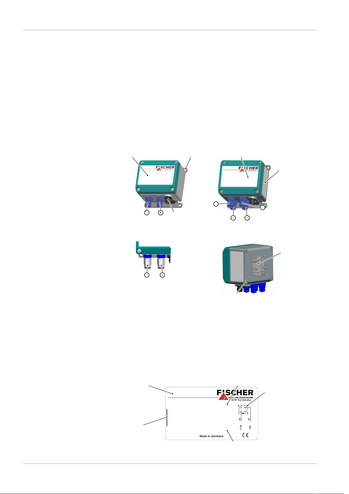
2.3 Equipment versions
6 / 20 BA_EN_DE23
Fig.1: Equipment versions
Nameplate
The presented type plates serve to show an example of the information shown.
The data shown is purely fictive, but does correspond to the actual conditions.
For more information, please see the order code at the end of these instructions.
1 channel version
Fig.2: Nameplate 2-wire
Page 7

FISCHER Mess- und Regeltechnik GmbH Product and functional description | 2
Silicone-free
Item number
Measuring range Δ P1
Output signal ΔP1 / ΔP2
Measuring range ΔP2
Pmax.
Operating voltage
DE23D4D440BR00MW
0 ... 100 Pa
4 ... 20 mA
100 kPa
24 V DC
1604446.01.002
Prod. No.
0 ... 100 Pa
Special properties Order Codes
Technical data
Serial number
Connector 1
Supply and
output signal
Circuit diagram
+U
-U
b
b
Channel2
A
D
D
A
µCΔP2
+
+Sig2
A
D
D
A
µCΔP1
+
Channel1
+Sig1
A
D
D
A
µCΔP1
+
Channel2
A
D
D
A
µCΔP1
+
Channel1
+U
b1
-U
b1
/+Sig1
/ -Sig1
+U
b2
-U
b2
/+Sig2
/ -Sig2
2 channel version
Fig.3: Nameplate 2-wire
2.4 Function diagram
Fig.4: Function diagram 3-wire (voltage output)
Fig.5: Function diagram 2-wire (current output)
2.5 Design and mode of operation
The basis of this transmitter is a sensor element with a produced differential
condenser made with silicon-glass technology.
The active pressure generates changes in capacity that is evaluated by the
device's electronics and transformed into an analogue signal 4…20mA or
0…10V.
BA_EN_DE23 7 / 20
The measuring channel are identical in the 2-channel models.
Page 8

3 | Assembly and Starting Operation FISCHER Mess- und Regeltechnik GmbH
1 channels
2 channels
+
P1
+ +
P1 P2
Higher pressure
lower pressure
Pressure
open
open
Under-pressure
3 Assembly and Starting Operation
3.1 Generalities
The device is designed for installation onto flat assembly plates. For screw connection to the assembly plate, the device features four assembly bores on its
back, which can be used for Ø 3.5 mm tapping screws.
Optionally, the device can be supplied with a wall mounting plate or an adapter
element for assembly with a mounting rail.
Ex-works, the device is set for vertical installation. Any installation position is
possible.
3.2 Process connection
• By authorized and qualified specialized personnel only.
• The pipes need to be depressurized when the instrument is being connected.
• Appropriate steps must be taken to protect the device from pressure surges.
• Check that the device is suitable for the medium being measured.
• Maximum pressures must be observed (cf. Tech. data)
CAUTION
Do not blow into the pressure connections.
This may damage the sensor.
The pressure lines must be kept as short as possible and installed without any
tight bends to avoid delays.
The process connections are marked with (+) and (-) symbols on the device.
The pressure lines must be mounted according to these symbols.
1. Differential pressure measurement
2. Pressure measurement
3. Under-pressure measurement
3.3 Electrical connections
• By authorized and qualified specialized personnel only.
• When connecting the unit, the national and international electro-technical
regulations must be observed.
• Disconnect the system from the mains, before electrically connecting the
device.
• Install the consumer-adapted fuses.
• Do not connect the connector if strained.
8 / 20 BA_EN_DE23
Page 9

FISCHER Mess- und Regeltechnik GmbH Assembly and Starting Operation | 3
P1
Supply 1
+Sig1
-Sig1
+U
b1
-U
b1
Output 1
Channel 1
1
3
+
-
+
P2
Supply 2
+Sig2
-Sig2
+U
b2
-U
b2
Output 2
Channel 2
4
2
+
-
+
3.3.1 2-wire connection (4 ... 20 mA)
Fig.7: M12 connector 4-pin
Fig.6: Electrical connections
1 channel version
Pin Description Cable colour
1 Supply/output (+) +U
+Sig brown
b
2 white
3 Supply/output (-) -U
b
-Sig blue
4 black
A Coding
2 channel version
Pin Description Cable colour
1 Supply 1 / output 1 (+) +U
2 Supply 2 / output 2 (-) -U
3 Supply 1 / output 1 (-) -U
4 Supply 2 / output 2 (+) +U
A Coding
+Sig1 brown
b1
-Sig2 white
b2
-Sig1 blue
b1
+Sig2 black
b2
BA_EN_DE23 9 / 20
Page 10

3 | Assembly and Starting Operation FISCHER Mess- und Regeltechnik GmbH
supply
P1
+Sig1
-Sig1
+U
b
-U
b
channel 1
1
3
+
-
+
4
+U
b
-U
b
P2
+Sig2
-Sig2
channel 2
+
-
+
2
output1
output2
(~)
(~)
3.3.2 3-wire connection (0 ... 10 V)
Fig.8: Electrical connections
Fig.9: M12 connector 4pol
1 channel version
Pin Description Cable colour
1 Supply (+)(~) +U
2 white
3 Supply (-)(~) -U
4 Output (+) +Sig black
A Coding
2 channel version
Pin Description Cable colour
1 Supply (+)(~) +U
2 Output 2 (+) +Sig2 white
3 Supply (-)(~) -U
4 Output 1 (+) +Sig1 black
A Coding
3.4 Commissioning
A prerequisite for commissioning is correct installation of all electrical supply
lines and the pressure lines. All connections are arranged so that there are no
mechanical forces acting on the device.
CAUTION
Leak test
The pressure lines need to be checked for leaks before commissioning.
The device switches into normal mode as soon as the device is connected to a
power supply.
b
-Sig blue
b
b
-Sig1 / -Sig2 blue
b
brown
brown
10 / 20 BA_EN_DE23
Page 11

FISCHER Mess- und Regeltechnik GmbH Maintenance | 4
4 Maintenance
4.1 Maintenance
The instrument is maintenance-free. We recommend the following regular inspection to guarantee reliable operation and a long service life:
• Check the function in combination with downstream components.
• Check the leak-tightness of the pressure connection lines.
• Check the electrical connections.
The exact test cycles need to be adapted to the operating and environmental
conditions. In combination with other devices, the operating instructions for the
other devices also need to be observed.
4.2 Transport
The measuring device must be protected against impacts. It should be transported in the original packaging or a suitable transport container.
4.3 Service
All defective or faulty devices should be sent directly to our repair department.
Please coordinate all shipments with our sales department.
WARNING
Process media residues
Process media residues in and ondismantled devices can be a hazard to
people, animals and the environment. Take adequate preventive measures. If
required, the devices must be cleaned thoroughly.
Return the device in the original packaging or a suitable transport container.
4.4 Accessories
• M12 Connection lines of different lengths
(see order code [}16])
• Wall mounting set
4.5 Disposal
WARNING
Incorrect disposal may pose a risk to the environment.
Please help to protect the environment by always disposing of the work pieces
and packaging materials in compliance with the valid national waste and recycling guidelines or reuse them.
BA_EN_DE23 11 / 20
Page 12

5 | Technical Data FISCHER Mess- und Regeltechnik GmbH
5 Technical Data
5.1 Generalities
Reference conditions (acc. to IEC 61298-1)
Temperature +15 … +25 °C
Relative humidity 45 … 75 %
Air pressure 86 … 106 kPa 860 … 1060 mbar
Installation position User-defined
All information in the technical data refer to one measuring value channel. The
technical data for the second measuring value channel is identical and is therefore not listed.
5.2 Input variables
Measured variable
Differential pressure, positive and negative over-pressure
Mearuring ranges
Relative pressure +/- measuring ranges asymmetric
0 … 25 Pa ± 25.0 Pa -20 … +80 Pa
0 … 50 Pa ± 50.0 Pa
0 … 100 Pa ± 100.0 Pa
0 … 250 Pa ± 250.0 Pa
0 … 500 Pa
0 … 1000 Pa
For all measuring ranges:
Max. system pressure stat. pressure 1 bar
Bursting pressure on
1,7 bar
one side
5.3 Output sizes
Current output Voltage output
Output signal 4 … 20 mA 0 … 10 V
Apparent ohmic resist-
RL ≤ (Ub-12 V)/0.02 A
ance
Characteristic curve linear linear
Connection type 2-Wire 3-Wire
5.4 Measurement accuracy
Characteristic curve deviation
1)
1 % FS
Reproducibility 0.1 % FS
TK zero-point and range
3)
0.6 % FS / 10 K
Long-term stability ≤ 0.5 % FS / year
Response time (10 … 90 %) 250 ms
1)
Non-linearity and hysteresis at 25 °C
2)
FS: Full Scale (measurng range span)
3)
Compensation range 4 … 50 °C
2)
12 / 20 BA_EN_DE23
Page 13

FISCHER Mess- und Regeltechnik GmbH Technical Data | 5
5.5 Auxiliary energy
Rated Voltage 24 V DC 24 V AC 24 V DC
Adm. operating voltage 19 … 36 V 19,2 … 28,8 V 14 … 36 V
Power consumption
(per chanel)
5.6 Application conditions
Increase ambient temperature
Media temperature -10 … +60 °C
Storage temperature -20 … +70 °C
Enclosure protection class IP65 as per EN 60529
EMC EN 61326-1:2013
RoHS EN 50581:2012
5.7 Construction design
5.7.1 Process connection
All device models are available with the following process connections:
2-wire
(4 … 20 mA)
Max. 20 mA Max. 6 mA
-10 … +60 °C
EN 61326-2-3:2013
3-wire
(0 … 10 V)
Hose screw connection
(aluminium anodised)
Pneumatic plug connector for 6/4 mm hose
5.7.2 Electrical connection
M12 round plug connector, 4-pin, male, A-coding
5.7.3 Materials
Housing Polyamide PA 6.6
Has contact to the
medium
5.7.4 Assembly
Attachment boreholes on the rear side for attachment to mounting plates.
Assembly of the mounting rails using an adapter element.
Wall mounting using wall mounting plate
for 6/4 mm hose
for 8/6 mm hose
for 8/6 mm hose
Silicon, PVC, aluminium, brass
BA_EN_DE23 13 / 20
Page 14

5 | Technical Data FISCHER Mess- und Regeltechnik GmbH
Attachment boreholes on rear side
90
76
70.5
61.5
26
75
83
Ø5
M12 plug
Screw connection
Pneumatic plug connector
Wall mounting plate
Boreholes for tapping screws diam. 3.5 mm
78
63
5.7.5 Dimensional drawings
All dimensions in mm unless otherwise stated
Wall-mounting
14 / 20 BA_EN_DE23
Fig.10: Dimension drawing
Page 15

FISCHER Mess- und Regeltechnik GmbH Technical Data | 5
Adapter element
38
36
2525
40
61.5
TS35
TS35
TS15
TS32
40 36
35
35
15
32
16242121
7.5
155
15
Assembly of the mounting rails
Fig.11: Assembly of the mounting rails
BA_EN_DE23 15 / 20
Fig.12: Mounting rails options
Page 16

6 | Order Codes FISCHER Mess- und Regeltechnik GmbH
Process connection
Output signal
Operating voltage
Measured value display
Electrical connection
Assembly
Type
Measuring channel 1
Code no.
D E 2 3 0 0 M
1 2 5 6 7 8 9 10 11 123 4
Measuring channel 2
6 Order Codes
Measuring range channel 1:
[1,2] (Code no.)
D1 0 … 25 Pa
J6 0 … 50 Pa
D4 0 … 100 Pa
D6 0 … 250 Pa
J7 0 … 500 Pa
D9 0 … 1000 Pa
L5 ± 25.0 Pa
L2 ± 50.0 Pa
L0 -20 … +80 Pa
L7 ± 100.0 Pa
L6 ± 250.0 Pa (only versions 4...20 mA, 2-wire)
Measuring range channel 2:
[3,4] (Code no.)
00 without
D1 0 … 25 Pa
J6 0 … 50 Pa
D4 0 … 100 Pa
D6 0 … 250 Pa
J7 0 … 500 Pa
D9 0 … 1000 Pa
L5 ± 25.0 Pa
L2 ± 50.0 Pa
16 / 20 BA_EN_DE23
L0 -20 … +80 Pa
L7 ± 100.0 Pa
L6 ± 250.0 Pa (only versions 4...20 mA, 2-wire)
Page 17

FISCHER Mess- und Regeltechnik GmbH Order Codes | 6
Process connection:
[5,6] (Code no.)
40 Aluminium hose screw connection anodised for 6/4 mm hose
41 Aluminium hose screw connection anodised for 8/6 mm hose
P6 Pneumatic plug connector for 6/4 mm hose
P8 Pneumatic plug connector for 8/6 mm hose
Output signal/Operating voltage:
[7,8] Output signal Operating voltage
BR 4 … 20 mA 2-wire connection 24 V DC
CL 0 … 10 V 3-wire connection 24 V AC/DC
Measured value display:
[10] (Code no.)
0 none
Electrical connection:
[11] (Code no.)
M M12 plug connection
Assembly options:
[12] (Code no.)
0 Attachment boreholes on rear side (standard)
S Assembly on mounting rails
W Wall-mounting
6.1 Accessories
Order no. Planned measures No. of
Poles
06401993 Connection cable with M12 connector 4-pin 2 m
06401994 Connection cable with M12 connector 4-pin 5 m
04005144 Wall mounting set
Length
BA_EN_DE23 17 / 20
Page 18

7 | Annex FISCHER Mess- und Regeltechnik GmbH
7 Annex
Fig.13: CE_DE_DE23
18 / 20 BA_EN_DE23
Page 19

FISCHER Mess- und Regeltechnik GmbH Annex | 7
BA_EN_DE23 19 / 20
Page 20

7 | Annex FISCHER Mess- und Regeltechnik GmbH
20 / 20 BA_EN_DE23
 Loading...