

Page 1

FAllOC Security System
Previous
N5100-7v19/96
Page 2
TABLE OF CONTENTS
SYSTEM OVERVlEW
Keypads
Zones
Afans
Fire Protection
Burglary Protection
Memory of Alarm..
Pager Notification
ABOUTTHE KEYPADS
Keypad Types
Keypad Styles
SUMMARY OF SYSTEM STATUS DISPLAYS
SUMMARY OF KEYPAD FUNCTIONS
SECURlTY CODES
Duress Code ............................................................................................................................................
Quick Am-ring
Assigning/ChangingiDeleting User Codes (Using the HCODE Key)
ENTRY/EXlT
CHECKING FOR OPEN ZONES (Using the q READY Key)
BYPASSING PROTECTlON ZONES
Using The q BYPASS Key
Quick Bypass
ARMING PERIMETER ONLY, WlTH ENTRY DELAY ON (Using The m STAY
ARMING PERIMlzR ONLY, WfTH ENTFtY DELAY OFF (Using The @INSTANT Key )
ARMING ALL PROTECTION, WlTH ENTRY DELAY ON (Using The @AWAY Key)
ARMING AU PROTECTION, WfTH
DISARMING THE SYSTEM AND SILENCING ALARMS (Using the HOFF Key)
...................................................................................................................................................
.......................................................................................................................................................
......................................................................................................................................................
DELAYS..
....................................................................................................................................... 4
............................................................................................................................................ 5
.....................................................................................................................................
.......................................................................................................................................
.......................................................................................................................................
....................................................................................................................................
...........................................................................................................................................
...........................................................................................................................................
........................................................................................................
...................................................................................................................
.........................................................................................................................................
...........................................................................................................................................
....................................................................
..................................................................................................................................
...................................................................................
...................................................................................................................
..........................................................................................................................
...........................................................................................................................................
....................................................... 16
Key)
................................................
.......................................................
q
ENTRY DELAY OFF (Using The
-2-
MAXIMUM Key) ............................................... .19
..........................................................
4
4
5
5
5
5
6
6
6
7
8
10
.10
-10
11
.12
13
14
14
15
17
18
20
Page 3

(continued)
USlNGME KEYSWITCH
CHIME MODE
PANlcKEYS
TESTING THE SYSTEM (Using the HTEST Key) ................................................................................................
TROUBLE CoNDrnoNS
‘ChedC and ‘Battery’ Displays
Power Failure ...........................................................................................................................................
Other Displays .........................................................................................................................................
FIRE ALARM
In case of Fire Alarm
Silenoing Fire Alarms .................................................................................................................................
NATIONAL
EMERGENCY EVACUATION
QUICK GUIDE TO ALARM SYSTEM
SUMMARY OF AUDlBLE/VlSUAL NOTlFlCATfON
PROTECTION
OWNER’S
CANAMAN DEPARTMENT OF COMMUNlCATlONS (DOC) STATEMENT
FEDERAL COMMUNlCATlONS COMMISSION (FCC) STATEMENTS
INMEEVENTOF TELEF%XEOPEl?ATlONALPROBLEMS
THE LlMlTATlONS OFTHIS ALARM SYSTEM
SERVlClNG
WARRANTY
This manual is a step-by-step guide that will aquaint you with the system’s features and benefll. It defines the
components and their funotions, describes their operation, and instructs you wfth normal and emergency prooedures.
Keep this manual in a convenient place so that you can refer to ft as necessary.
(using the BCHIME Key)
................................................................................................................................................
SYSTEM, IF INSTALLED.. .............................................................................................................
Fl RE PROTECTION ASSOClATlON
ZONES UST..
INSURANCE PREMIUM CREDIT
INFORMATlON
.....................................................................................................................................
................................................................................................................................
.................................................................................................................................
..........................................................................................................................
............................................................................................................................
.............................................................................................................................
TABLE OF CONTENTS
..........................................................................................................
...................................................................................................................
..................................................................................................................................
RECOMMENDATIONS
FUNCTlONS
..................................................................................................
...............................................................................................
REQUEST.. .........................................................................................
.................................................................................
......................................................................................................
ON SMOKE DETECTORS..
....................................................................
.........................................................................
................................
Bad< cover
21
.22
22
24
26
.26
27
27
28
28
29
.30
-31
32
.S3
34
35
37
36
39
40
41
Page 4
SYSTEM OVERVIEW
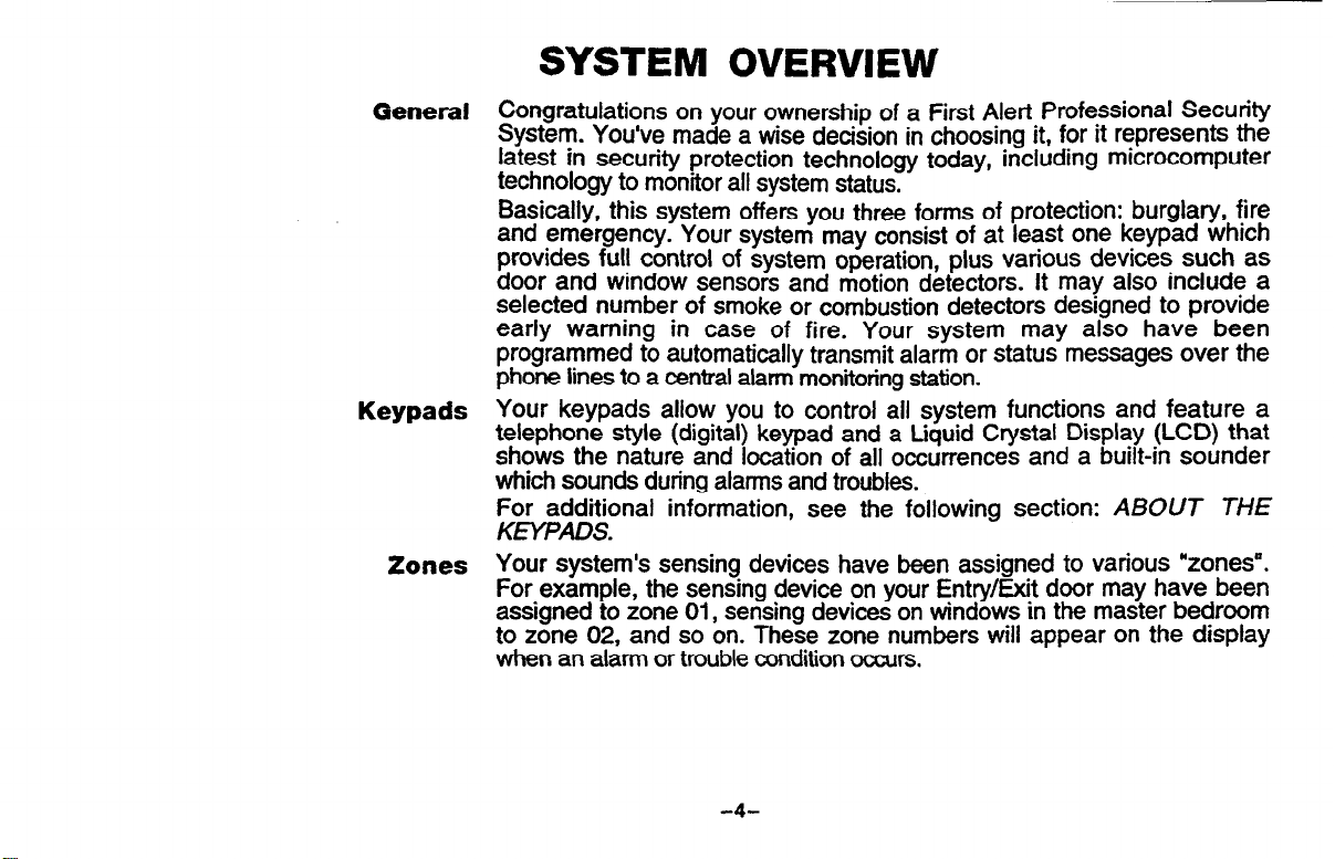
General Congratulations on your ownership of a First Alert Professionat Security
System. You’ve made a wise decision in choosing it, for it represents the
latest in security protection technology today, including miCrOCOmpUter
technology to monitor all system status,
Basically, this system offers you three forms of protection: burglary, fire
and emergency. Your system may consist of at least one keypad which
provides full control of system operation, plus various devices such as
door and window sensors and motion detectors. It may also include a
selected number of smoke or combustion detectors designed to provide
early warning in case of fire. Your system may also have been
programmed to automatically transmit alarm or status messages over the
phone lines to a central alarm monitoring station.
Keypads
Zones
Your keypads allow you to control all system functions and feature a
telephone style (digital) keypad and a Liquid Crystal Display (LCD) that
shows the nature and location of all occurrences and a built-in sounder
which sounds during alarms and troubles.
For additional information, see the following section: ABOUT THE
KEYPADS.
Your system’s sensing devices have been assigned to various “zones”.
For example, the sensing device on your Entry/Exit door may have been
assigned to zone 01, sensing devices on windows in the master bedroom
to zone 02, and so on. These zone numbers will appear on the display
when an alarm or trouble condiion occurs.
-4-
Page 5
(continued)
Fire Protection
Burglary Protection
Memory Of Alann
Pager Notification
SYSTEM OVERVIEW
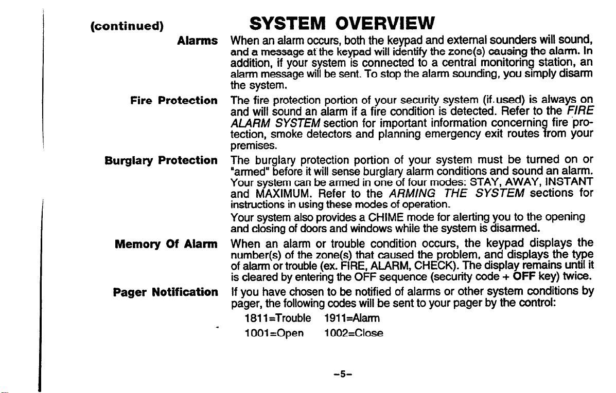
Alarms When an alarm occurs, both the keypad and external sounders will sound,
and a message at the keypad will identify the zone(s) causing the alarm. In
addition, if your system is connected to a central monitoring station, an
alarm message will be sent. To stop the alarm sounding, you simply disarm
the system.
The fire protection portion of your security system (ii.used) is always on
and will sound an alarm if a fire condition is detected. Refer to the FIRE
ALARM SYSTEM section for important information concerning fire .protection, smoke detectors and planning emergency exit routes from your
premises.
The burglary protection portion of your system must be turned on or
“armed” before it will sense burglary alarm conditions and sound an alarm.
Your system can be armed in one of four modes: STAY, AWAY, INSTANT
and MAXIMUM. Refer to the ARM/h/G THE SYSTEM sections for
instructions in using these modes of operation.
Your system also provides a CHIME mode for alerting you to the opening
and closing of doors and windows while the system is disarmed.
When an alarm or trouble condition occurs, the keypad displays the
number(s) of the zone(s) that caused the problem, and displays the type
of alarm or trouble (ex. FIRE, ALARM, CHECK). The display remains until it
is cleared by entering the OFF sequence (security code +
If you have chosen to be notified of alarms or other system conditions by
pager, the following codes will be sent to your pager by the control:
1811 =Trouble
a
1001 =Open
191 l=Alarrn
1002=Close
OFF
key) twice.
-5
Page 6

ABOUT THE KEYPADS
Keypad Types
Keypad Styles
dures in this man-
ual apply equally to
all keypad types
and sty/es.
All commands and procedures described herein are illustrated for FixedWord Display keypads, however, an Alpha Display keypad (with a e-line
LCD display for more detailed protection point identification and system
status, but with similar commands and procedures) is available and might
have been used instead.
Faed-Word keypads are available in two display styfes, A and B, either of
which may have been used in your system. Although different in
appearance, both styles are functionally similar. The style B keypads
have a fliiwn door which can be removed, if desired. Words displayed
on all Fuced-Word keypads are the same, except that their location in the
display window diiers slightly with each style.
Note: Some keypads are equipped with a READY indicator in place of a
POWER rndrcator . The READY indicator is lii when the system is ready for
arming (no protection zones open). While the system is disarmed, this
indicator will go on and off as protection zones are opened and closed.
FIXED-WORD DISPLAY KEYPADS
SWLEA DISPLAY
- STYLE B DISPLAY,
-6-
Page 7
SUMMARY OF SYSTEM STATUS DISPLAYS
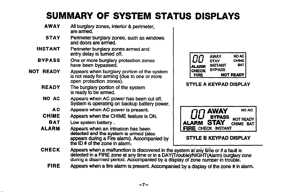
AWAY
STAY
INSTANT
BYPASS
NOT READY
READY
NO AC
AC
CHIME
BAT
ALARM
CHECK
FIRE
tkbut;y zones, interior & perimeter,
Perimeter burglary zones, such as windows
and doors are armed.
Perimeter burglary zones armed and
entry delay is turned off.
One or more burglary protection zones
have been bypassed.
Appears when burglary portion of the system
is not ready for arming (due to one or more
open protection zones).
The burglary portion of the system
is ready to be armed.
Appears when AC power has been cut off.
System is operating on backup battery power.
Appears when AC power is present.
Appears when the CHIME feature is ON.
Low system battery.
Appears when an intrusion has been
detected and the system is armed (also
appears during a Fire alarm). Accompanied by
the ID # of the zone in alarm.
Appears when a maffunction is discovered in the system atany trme or if a f&t is
detected in a PlRE zone at any time or in a DAY(Troubie)/NlGHT(Alarm) burglary zone
during a disarmed period. Accompanied by a display of zone number in trouble.
Appears when a fire alarm is present. Accompanied by a display of the zone # in alarm.
.
STYLE A KEYPAD DISPLAY
21
STYLE B KEYPAD DISPLAY
4
- .-.-
-7-
Page 8
SUMMARY OF KEYPAD FUNCTIONS
1.
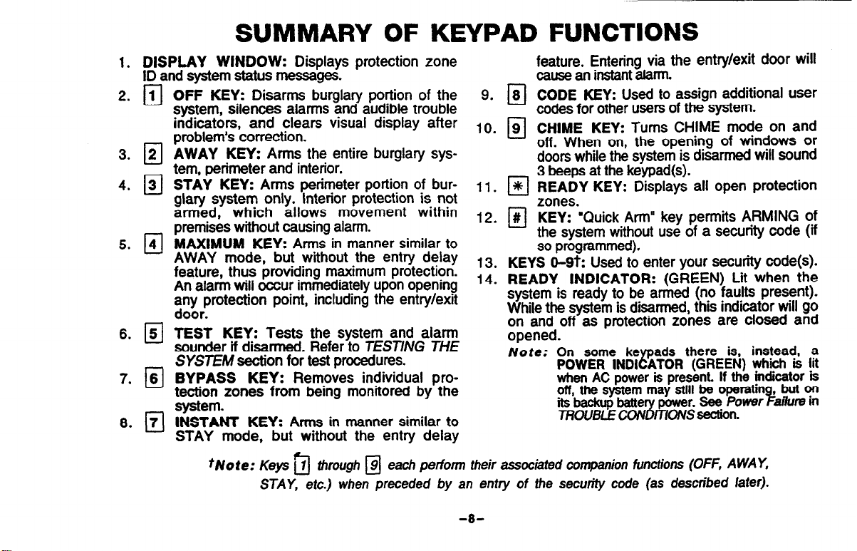
DISPLAY WINDOW:
ID and system status messages.
OFF KEY: Disarms burglary portion of the 9.
system, silences alarms and audible trouble
indicators, and clears visual display after ,Q
problem’s correction.
AWAY KEY: Arms the entire burglary system, perimeter and interior.
STAY KEY: Arms perimeter portion of bur- 11.
glary system only. Interior protection is not
armed, which allows movement within l2
premises without causing alarm.
MAXIMUM
AWAY mode, but without the entry delay
feature, thus providing maximum protectron.
An alarm will occur immediately upon opening
any protection point, including the entry/exit
door.
TEST
KEY:
sounder if disarmed. Refer to TESTING THE
SYSTEM section for test procedures.
BYPASS
KEY: Removes individual protection zones from being monitored by the
system.
INSTANT KEY: Arms in manner similar to
STAY mode, but without the entry delay
tNote:
Displays protection zone
KEY:
Arms in manner similar to
Tests the system and alarm
F-l -
Keys ilJ through M each perform their associated companion functions (OFF, AWAY,
STAY,
etc.) when
preceded by
13.
,4
-
an entry
feature. Entering via the entry/exit door will
cause an instant alarm.
CODE KEY: Used to assign additional user
8
q
codes for other users of the system.
CHIME KEY:
9
0
off. When on, the opening of windows or
Turns CHIME mode on and
doors while the system is disarmed will sound
3 beeps at the keypad(s).
READY KEY: Displays all open protection
El
zones.
KEY: “Quick Arm” key permits ARMING of
#
cl
the system
without use of a security code (if
so programmed).
KEYS Q-9t: Used to enter your security code(s).
READY
INDICATOR:
(GREEN) Lit when the
system is ready to be armed (no faults present).
While the system is disarmed, this indicator will go
on and off as protection zones are closed and
opened.
Note:
On some ke
POWER
when AC power is present. If the indicator is
off, the system may
its backup baite
TROUBLECON
of the security code (as described later).
ads there is, instead, a
INDI
P
ATOR
?i
(GREEN) which LS lit
still
be operatin
power. See Power a&e in
mO!VSsection.
, but on
%
-8-
Page 9
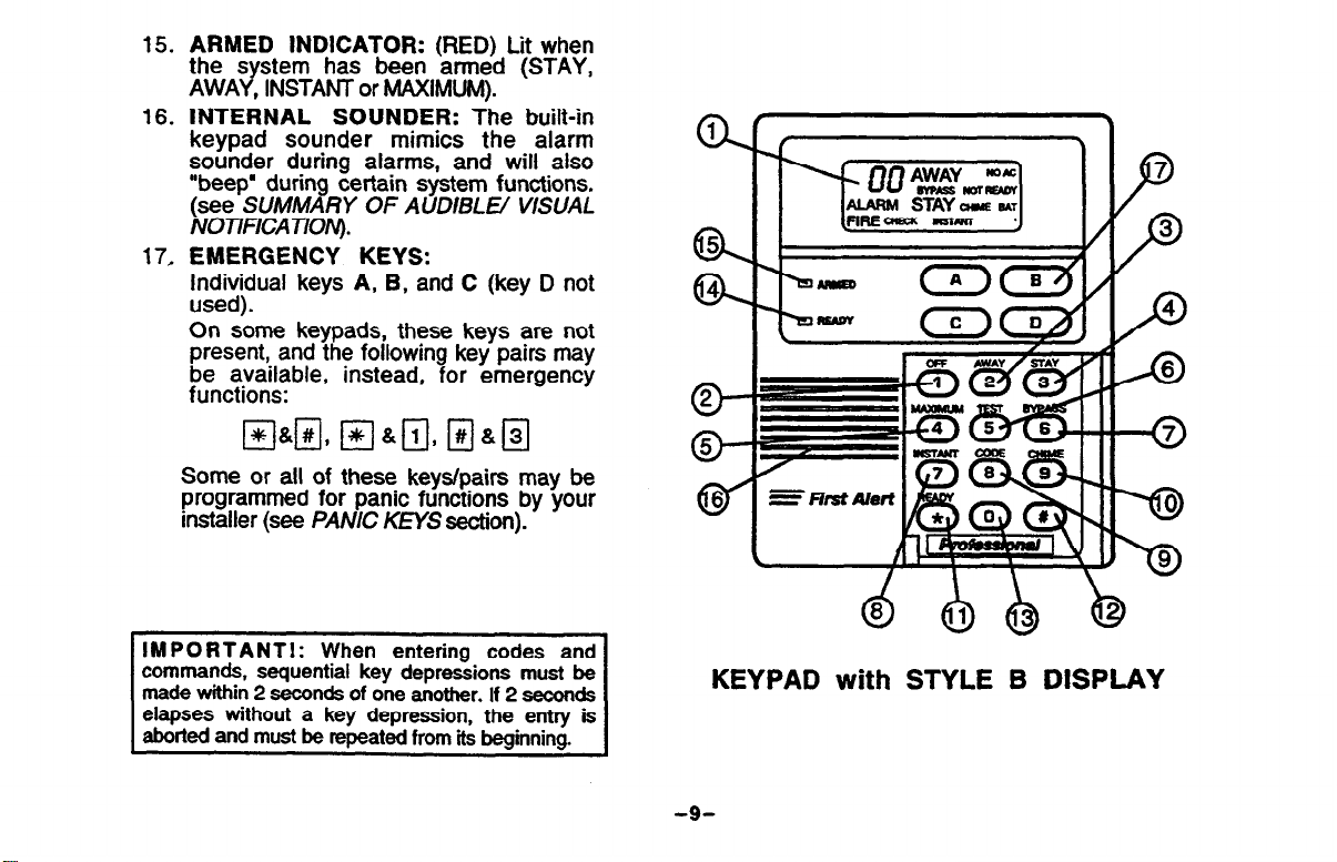
15. ARMED INDICATOR:
the s stem
AWA Y
, INSTANT or MAXIMUM).
16.
INTERNAL SOUNDER:
has been armed (STAY,
(RED) Lit when
The built-in
keypad sounder mimics the alarm
sounder during alarms, and will also
“beep’ during certain system functions.
(see SUMMARY OF AUDIBLE/ VISUAL
NOTIFEATION).
17, EMERGENCY KEYS:
Individual keys
A, B,
and C (key D not
used).
On some keypads, these keys are not
present, and the following key pairs may
be available, instead, for emergency
functions:
Some or all of these keys/pairs may be
programmed for panic functions by your
installer (see PANIC KEYS section).
IMPORTANTI: When entering codes and
commands, sequential key depressions must be
made within 2 seconds of one another. If 2 seconds
elapses without a key depression, the entry is
aborted and must be repeated from its beainnina.
KEYPAD with STYLE B DISPLAY
-9-
Page 10
SECURITY CODES
General
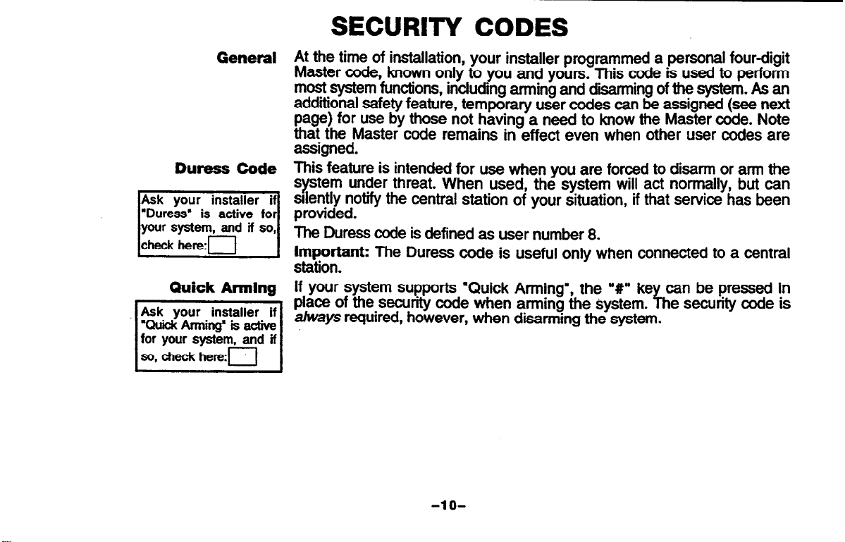
Duress Code
Quick hing
At the time of installation, your installer programmed a personal four-digit
Master code, known only to you and yours. This code is used to perform
most system functions, including arming and d&arming of the system. As an
additional safety feature, temporary user codes can be assigned (see next
page) for use by those not having a need to know the Master code. Note
that the Master code remains in effect even when other user codes are
assigned.
to disarm or arm the
normally, but can
service has been
Important: The Duress code is useful only when connected to a central
station.
ke
If your system supports ‘Quick Arming”, the V”
place of the security code when arming the system.
required, however, when disarming the system.
can be pressed in
f-h
e security code is
-1 o-
Page 11
(continued)
SECURITY CODES
To Assign, Change,
Or Delete
User Codes
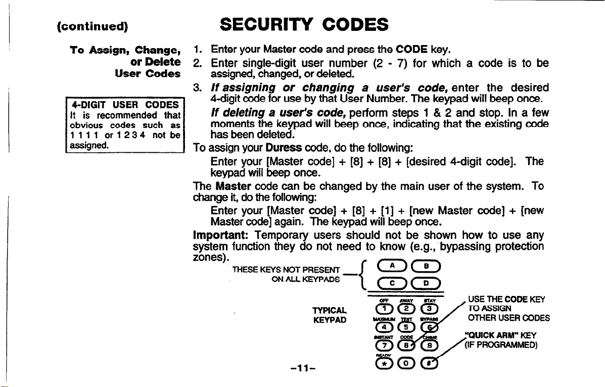
1. Enter your Master code and press the CODE key.
2. Enter single-digit user number (2 - 7) for which a code is to be
assigned, changed, or deleted.
3. If assigning or changing a user’s code, enter the desired
4digit code for use by that User Number. The keypad will beep once.
If deleting a user’s code, perform steps 1 & 2 and stop. In a few
moments the keypad will beep once, indicating that the existing code
To assign your Duress code, do the following:
Enter your [Master code] + [8] + [8] + [desired 4digit code]. The
keypad will beep once.
The Master code can be changed by the main user of the system. To
change it, do the following:
Enter your [Master code] + [8] + [l] + [new Master code] + [new
Master code] again. The keypad will beep once.
Important: Temporary users should not be shown how to use any
system function they do not need to know (e.g.;bypassing protection
zones).
THESE KEYS NOT PRESENT
ON ALL KEYPADS -
TYPiCAL
KEYPAD
<I)(B)
<c
wirrw CulE
USE THE CODE KEY
TO ASSIGN
OTHER USER CODES
“OUICK ARM” KEY
-ll-
Page 12
ENTRY/EXIT DELAYS
General hformation
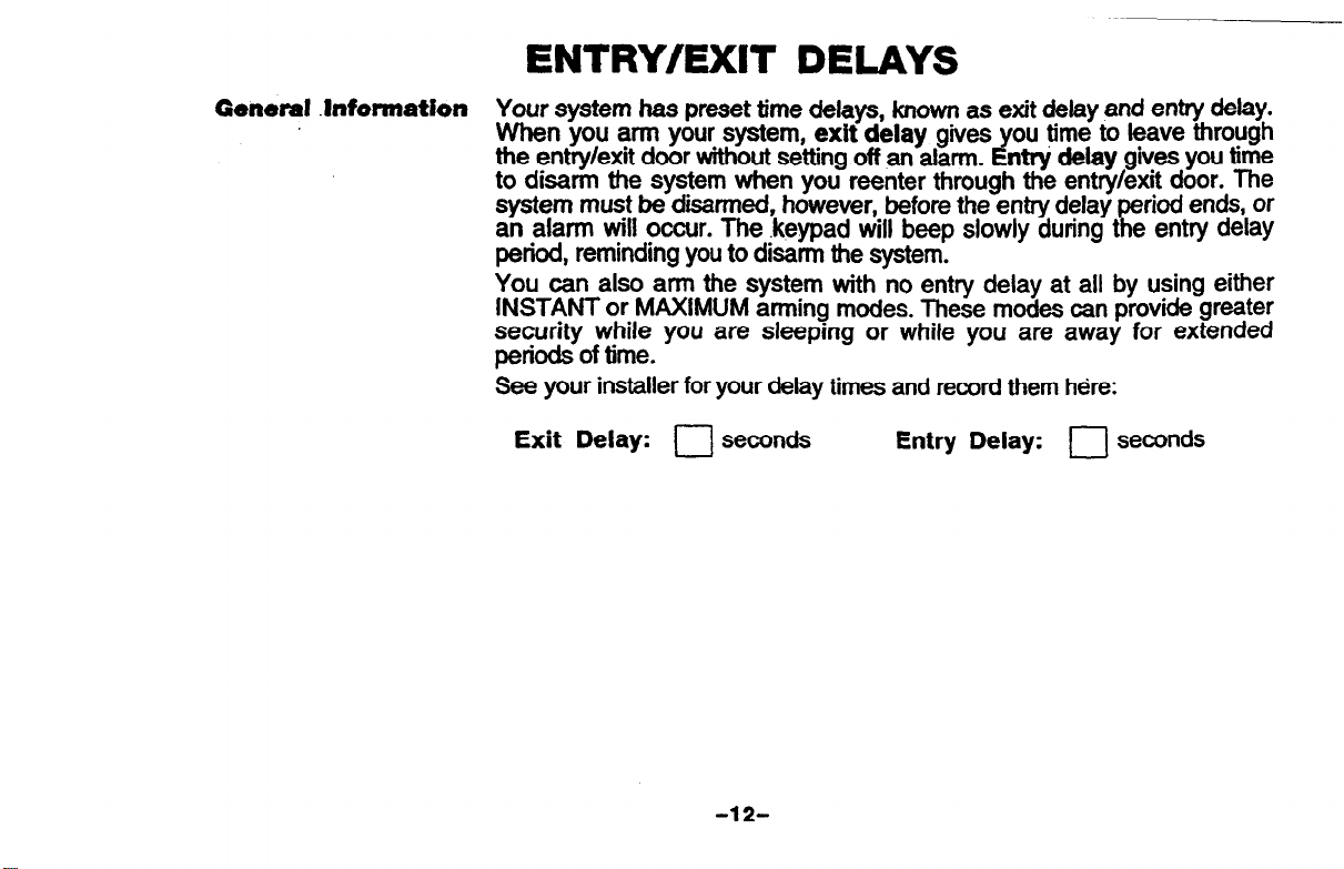
Your system has preset time delays, known as exit delay and entry delay.
When you arm your system, exit delay gives ou time to leave through
the entry/exit door without setting off an alarm.
to disarm the system when you reenter through the entry/exit door. The
system must be disarmed, however, before the entry delay period ends, or
an alarm will occur. The .keypad will beep slowly during the entry delay
period, reminding you to disarm the system.
You can also arm the system with no entry delay at all by using either
INSTANT or MAXIMUM arming modes. These modes can provide greater
security while you are sleeping or while you are away for extended
periods of time.
See your installer for your delay times and record them here:
Exit Delay: 0 seconds
Entry Delay: 0 seconds
nttj delay
Y
gives you time
-12-
Page 13
CHECKING FOR OPEN ZONES
Using the
+k READY Key
cl
THESE KEYS NOT PRESENT -
ON ALL KEYPADS
TYPICAL
KEYPAD
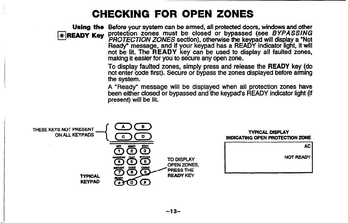
Before your system can be armed, all protected doors, windows and .o.ther
protection zones must be closed or bypassed (see BYPASSING
PROTECT/ON ZONES section), otherwise the keypad will display a ‘Not
Ready” message, and if your keypad has a READY indicator light, it will
not be lit. The READY key can be used to display all faulted zones,
making it easier for you to secure any open zone.
To display faulted zones, simply press and release the READY key (do
not enter code first). Secure or bypass the zones displayed before arming
the system.
A ‘Ready’ message will be displayed when all protection zones have
been either closed or bypassed and the keypads READY indicator light (if
present) will be lit.
INDICATING OPEN PROTECTION ZONE
TO MSPIAY
OPEN ZONES,
/PRESSTHE
READY KEY
TYPICAL DISPLAY
AC
NOT READY
-13-
Page 14
BYPASSING PROTECTION ZONES
Using the
3 BYPASS Key
0
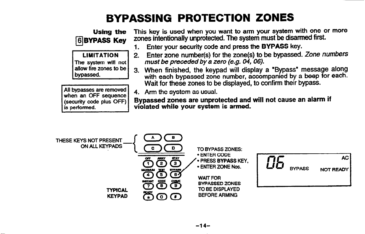
The system will not
allow fire zones to be
This key is used when you want to arm your system with one or more
zones
j.
2.
intentiOnaily Unprotected.
Enter your security code and press the BYPASS key.
Enter zone number(s) for the zone(s) to be bypassed. Zone numbers
must be preceded by a zero (e.g. 04, 06).
3. When finished, the keypad will display a “Bypass” message along
with each bypassed zone number, accompanied by a beep for each.
Wait for these zones to be displayed, to confirm their bypass.
$!,, 4. Arm the system as usual.
(seaJrity cor.le plus OFF)
is performed.
THESE KEYS NOT PRESENT
ONALLKEYPADS-
TYPICAL
KEYPAD
Bypassed zones are unprotected and will not cause an alarm if
violated while your system is armed.
(n)a
<c
TO BYPASS ZONES:
l
ENTER CODE
‘* PRESS BYPASS KEY,
l
ENTER ZONE Nos.
WAIT FOR
BYPASSED ZONES
TO BE DISPLAYED
BEFORE ARMING
The system must be disarmed first.
-.
-14-
Page 15

(continued)
BYPASSiNG PROTECTlON ZONES
Quick Bypass
‘Quick Bypass’ is
active for your
system, and if so,
If your s
all open faulted) zones without having to enter zone numbers individually.
To use this feature, enter your security code, press the BYPASS key,
then stop. In a few moments, all open zones will be displayed along with a
‘Bypass’ message. Wait for all bypassed zones to be displayed, then
arm the system as usual.
stem supports ‘Quick Bypass’, it allows you to easily bypass
r
TYPICAL “READY TO ARM” DISPLAY
SYSTEM
CAN NOW
y
BE ARMED
WlTH ZONE(S)
BYPASSED
1
-1 s-
Page 16

ARIWNG PERIMETER ONLY
WRN ENTRY DELAY ON
Using the
THESE KEYS NOT PRESENT-
ON ALL KEYPADS
TYPICAL
KEYPAD
Use thii key when you are staying inside, but expect someone to
use an entry/exit door later.
1. Enter your security code and press the STAY key.
2. The keypad beeps three times and displays the armed message. ihe
red ARMED indicator lights.
3. The system arms. An alarm sounds immediately if a protected perimeter
window or non-entry/exit door is then opened, but you may othewse
move freely throughout the premises.
Later arrivals can enter through an entry/exit door without causing
an alarm, but they must disarm the system within the entry delay
period to avoid sounding an alarm.
an
<c
{
THE STAY KEY ARMS
THE PERIMETER, SUT
ALLOWS USE OF THE
ENTRY/ExrroooR
.,
TyplCAL’ARMED STAY” DlspLAY
STAY
AC
-16-
Page 17

ARMING PERIMETER ONLY
WITH ENTRY DELAY OFF
Using the Use this key when you are staying inside and do not expect
anyone to use an entry/exit door.
1. Enter your security code and press the INSTANT key.
2. The keypad beeps three times and displays the armed message. The
red ARMED indicator lights.
3. The system arms. An alarm sounds immediately if any protected
perimeter door or window is then opened, but you may otherwise move
freely throughout the premises.
An alarm sounds immediately if anyone opens an entry/exit door.
THESE KEYS NOT PRESENT
ON ALL KEYPADS-
-17-
Page 18

ARMING ALL PROTECTION
WfTH ENTRY DELAY ON
Using the Use this key when no one will be staying inside.
MAWAY Key 1.
Enter your security code and press the AWAY key.
2. The keypad beeps twice and displays the armed message. The red
Aft& exit delay, the system arms and sounds an alarm if a protected
window or non-entry/exit door is then opened, or if any movement is
detected inside your premises.
You may reenter through an entry/exit door, but must disarm the
system within the entry delay period to avoid an alarm.
THESE KEYS NOT PRESENT
ON ALL KEYPADS
TYPICAL
KEYPAD
-
<A
<CD
THE AWAY UEY ARMS
’ THE ENTIRE SYSTEM
(INTERIOR AND
PERIMEIER), BUT
ALLOWS USE OF THE
ENTRY/EXIT DOOR
-18-
MPlCAL “ARMED AWAY” DISPLAY
AWAY
AC
Page 19

Using the Use this key when the premises will be vacant for extended
A:YI?
Acl
@MAXIMUM ~~~
1 REFnRE
--. v--v
close all doors and windows
(see CHECKING FOR OPEN
I
1 ZONES on
ARMING
1
page 13).
ARMfNG ALL PROTECTION
WITH ENTRY DELAY OFF
periods ?f time such as vacations, etc., or when retiring for the night and
no one
1.
2. The keypad beeps twice and displays the armed message. The red
] 3.
An alarm sounds immediately, when someone reenters.
mll
be moving through protected interior areas.
Enter your securfty code and press the MAXIMUM key.
ARMED indicator lights.
You may leave through an entry/exit door during the exit delay period
without causing an alarm.
After exit delay, the system arms and sounds an alarm immediately if
any protected door or window is opened, or if any movement is
detected inside your premises.
THESE KEYS NOT PRESENT
ON ML KEYPADS -
TYPICAL
KEYPAD
<A
<c)<D)
THE,MAXlMlJM KEY
ARMS THE ENTIRE
SYSTEM (INCLUDING
ME ENTRY/EXIT
DCOR, WITH NO
ENTRY DELAY)
-19-
TYPEAL “ARMED MAXIMUM” DISPLAY
I
Page 20

DISARMING THE SYSTEM AND SILENCING ALARMS
Using the The OFF key is used to disarm the system and to silence alan and
HOFF
U
IMPORTANT:
ff you return and the
main burglary sounder
CONTACTTHE POLICE
fromanearhysafelocatfon.
If you return after an
afarm has occurred and
has shut itself off:
the keypad will beep rapidly
won your en&rim. indicatim
-that -in alarm h&-ocamed-
)he Memory of Alarm feature).
LENNEl~~EDl~~Dld
from a nearby safe location.
WHENSAFETODOSO,
andfollowtheprccedure
for
is on:
DOf4OTENTERbkJt
the main sounder
during your absence
reenter
silencing
an alarm.
Key
trouble sounds.
To Disarm the System
Enter your security code and press the OFF key. The “Ready” massage
will be displayed, and the keypad will emit a single tone to confirm that the
system is disarmed.
To Silence a Burglary Alarm
SEE IMPORTANT NOTE AT LEFT!
Enter your security code and press the OFF key to silence the alarm (or
warning tones of a Memory of Alarm). Note the zone in alarm on the
keypad display, and make that zone intact (close door, window, etc.). Now
enter the security code plus OFF sequence again to clear the keypad’s
Memory of Alarm display. If the display will not clear and does not provide
a “Ready message, notify the alarm agency.
To Silence a Fire Alarm simply press the OFF key (the security code is
not needed to silence FIRE alarms). To then clear the keypad’s Memory of
Alarm display, enter your security code and press the OFF key.
See page 28 for additional fire alarm information.
See the SUMMARY OF AUDIBLE/VISUAL NOTlFlCATiON section
for information which will help you to distinguish between FIRE
(I~l~ptedlPulsed) and BURGLARY (Continuous/Steady) alarm
.
-2o-
Page 21

USING THE KEYSWITCH
General Your system may be equipped with a keyswitch for use when arming and
disarming. A single red light on the keyswitch plate indicates the status of
your system as follows:
OFF = Disarmed, Not Ready for Arming
SLOW FLASHING =
RAPID FLASHING =
Arming To arm in the AWAY mode, turn key to right for 112 second.
To arm in the STAY mode, hold key turned to right for more than one
second.
The keypads will beep twice (AWAY mode) or 3 times (STAY mode) and
the keyswitch light will flash rapidly.
Disarming To disarm the system turn the key to the right and release.
If an alarm has occurred during the armed period, the keyswitch’s light will
not flash on disarming (thus indicating memory of an alarm). Turning the
keyswitch key to the right a second time after disarming can clear the alarm
from memory, but it is advisable, instead, to refer to a keypad to diagnose
and clear any problem, and to subsequently clear alarm memory. See the
previous page for more about a/am, memory.
Disarmed, Ready for Arming
Armed STAY or AWAY’
-21-
Page 22

CHIME MODE
Using the Your system can be set to alert you to the opening of a door or window
while it is disarmed by using CHIME mode. When activated, three tones
will sound at the keypad whenever a protected door or window is opened.
Pressing the READY key will display the open points.
To turn Chime Mode on, enter the security code and press the CHIME
key. The CHIME message will appear.
To turn Chime Mode off, enter the security code and press the CHIME
key again. The CHIME message will disappear.
PANIC KEYS
Using
Panic Keys
(for manually activating
silent and/or
audible alarms)
TO INITIATE A PANIC
FUNCTION AT ANY
OF DAY OR NIGHT:
Press an
foratieasttwoseconds.
Press both keys of an active
pairatthesametime.
active
or
l
TfME
lettered key
If connected
Your system may have been programmed to use special keys or ccmbinations of keys to manually activate emergency (panic) functions. The
functions that might be programmed are: Silent Emergency, Audible
Emergency, Personal Emergency, and Fire.
A silent emergency will send a silent alarm signal to the central station*,
but there will be no audible alarms or visual displays.
An audible emergency will send a signal to the central station* and
sound a loud, steady alarm at your keypad(s) and at any external
sounders that may be connected (ALARM plus a zone number would also
be displayed).
A personal emergency alarm will send an emergency message to the
central station* and will sound at keypad(s), but not at external bells or
sirens.
A ore alarm will send a fire alarm message to the central station* and will
unrquely sound at ke
zone number would
ad(s) and external bells and sirens (FIRE plus a
r)
a so be displayed).
-22-
Page 23

(continued)
PANIC KEYS
THESE KEYS NOT PRESENT
ON ALL KEYPADS
SEE YOUR lNSTALLER
AND NOTE HERE
THE KEY(S) & FUNCTlON(S)
PRDGRAMMED
FOR YOUR SYSTEM
-
TYPICAL
KEYPAD
0
cl
0.
l
KEYS IA], PI.
l
KEY [o], IF PRESENT ON YOUR KEYPAD, $i%iLA%?&E.
a(B)
E3c
Ill a WI
[*I a [#I
PI & VI
-sILpcT,-LuxBLE
AND [Cl ARE NOT PRESENT
_ LElTERED PANIC KEYS
(T IS NOT USED)
>
FllNI?tlnN
SlLENTEMERGENCY(Fbd-Ftirctim)
AUDIBLE EMERGENCY (Fucebhnction)
PANIC
KEYS
>
PERSONALLY, J
95
I
07
96
I
-23-
Page 24

Using
s TEST Key protection pofnt to be checked for proper operation.
q
NO ALARM REPORTd
WILL BE SENT TO THE
cENTRALMoNrroRlNG
STATION while the
systemisinTestmode. 1
the The TFST key puts your system into Test mode, which allows each
TESTING THE SYSTEM
TO BE CONDUCIED WEEKLY
1. Disarm the system and dose all protected windows, doors, etc. The
ke pad’s
i
‘cator (if wesent) should be lit.
nci
2 Enter your security code and press the TEST key.
I
3. The keypad will sound a single beep every 40 seconds as a reminder
that the system is in the test mode.
Each time a protection zone is faulted, the external siren or bell should
sound for one second and then turn off! while the keypad sounds 3 beeps.
If this does not happen, call for service rmmediately.
4. Open and close each protected door and window in turn and listen for
the required sounds The identification of each faulted protection point
should appear on the display.
5. Walk in front of any interior motion detectors (ff used) and listen for the
required sound as movement is detected. The identification of the
detector should appear on the display when it is activated.
READY message should be displayed and the READY
.
,
-240
Page 25

(continued)
TESTING THE SYSTEM
6.
Follow the manufacturer’s instructions to test all smoke detectors, to
ensure that all are functioning properly. The identification of each
detector should appear on the display when each is activated.
7.
After all protection points have been checked and restored, there
should be no zone identification numbers displayed. If a problem is
experienced with any protection point (no confirming sounds,
no display), CALL FOR SERVICE IMMEDIATELY.
8.
Turn off the Test mode by entering the security code and pressing the
OFF key.
-25-
Page 26

TROUi3LE CONDITIONS
%heck” and
“Battery” Displays
The word CHECK on the keypad’s display, accompanied by a ‘beeping’
at the keypad, indicates a trouble condition rn the system.
To silence the beeping for these conditions, press any key.
1. A display of “CHECK’ and one or more zone numbers indicates
that a problem exists with the displayed zone(s) and requires your
attention. If the CHECK display relates to a fire zone, CALL FOR
SERVICE IMMEDIATELY.
Determine if the zone(s) displayed are intact and make them so if they
are not. If the problem has been corrected, the display can he cleared if
you enter the OFF sequence (user code plus OFF key) twice. If the
display persists, CALL FOR SERVICE IMMEDIATELY.
2. A display of “BAT” with no zone number indicates that the main
standby battery in your control is weak. If this condition persists
for more than one day (with AC present), CALL FOR SERVICE.
AC
CHECK
I
-lYPfCAL =CHUX DWLAY
1
-26-
Page 27

(continued)
TROUBLE CONDITIONS
Power Failure
Other Displays
If there is no keypad display at all, and the POWER indicator (if
present) is not lit, operating power for the system has stopped and the
system is inoperative. CALL FOR SERVICE IMMEDIATELY.
If the message “AC LOSS” or “NO AC” is displayed, and the
POWER indicator (if present) is off, the keypad is operatmg on
battery power only. If only some lights are out on the premises, check circuit breakers and fuses and reset or replace as necessary. CALL FCR
SERVICE IMMEDIATELY if AC power cannot be restored.
dl:
If this remains displayed for more than 1 minute, your system is
disabled. CALL FOR SERVICE IMMEDIATELY.
cc:
The system is in communication with the central station for change of
function or status verification. If this message persists for more
than 10 minutes, CALL YOUR SERVICE COMPANY.
FC:
A communication failure has occurred. CALL FOR SERVICE
IMMEDIATELY.
oc
The keypad is not receiving signals from the control panel and sees
an open circuit. If this message persists for more than 70 mmutes,
CALL YOUR SERVICE COMPANY.
FOR SERVICING
INFORMATION,
I
SEE PAGE 41
I
-27-
Page 28

FIRE ALARM SYSTEM
IF INSTALLED
General
In Case Of Fire Alarm
Your fire alarm system (if installed) is on 24 hours a day, for continuous
protection. In the event of an emergency, the strategically located smoke
and heat detectors will automatically send signals to your system, triggering
a loud, interrupted sound from the keypad. An interrupted sound will also
be produced by optional exterior sounders. A FIRE message will appear at
your keypad and remain on until you silence the alarm.
1.
Should you become aware of a fire emergency before your detectors
sense the problem, go to your nearest keypad and manually initiate an
alarm by pressing the panic key pair assigned as FIRE emergency (if
programmed by the installer) as indicated on page 23.
2.
Evacuate all occupants from the premises.
3.
If flames and/or smoke are present, leave the premises and noMy your
local Fire Department immediately.
4.
If no flames or smoke are apparent, investigate the cause of the alarm.
The zone number(s) of the zone(s) in an alarm condition will be
displayed at the keypad.
AC
READY
TYPKXL TIRE EMERGENCY- DISPIAY
-28-
Page 29

(continued)
FIRE ALARM SYSTEM
IF INSTALLED
Silencing Fire Alarms 1.
2.
3.
4.
Silence the alarm by pressing the OFF key (security code not needed
to silence fire alarms). To dear the display, enter your code and press
the Off key again (Memory of Alarm).
If the keypad does not indicate a READY condition after the second
OFF sequence, press the READY key to display the zone(s) that are
faulted. Be sure to check that smoke detectors are not responding to
smoke or heat producing objects in their vicinity. Should this be the
case, eliminate the source of heat or smoke.
If this does not remedy the problem, there may still be smoke in the
detector. Clear it by fanning the detector for about 30 seconds.
When the problem has been corrected, clear the display by entering
your code and pressing the OFF key.
-29-
Page 30

NATIONAL FIRE PROTECTION ASSOClATlON
RECOMMENDATIONS ON SMOKE DETECTORS
General With regard to the number and placement of smoke/heat detectors, we
subs&e to the recommendations contained in the National Fire Protection
‘Association’s Standard #74 noted below.
Early warning fire detection is best achieved by the installation of fire
detection equipment in all rooms and areas of the premises as follows: A
smoke detector installed outside of each separate sleeping area, in the
immediate vicinity of the bedrooms and on each additional story of the
family living unit, induding basements and excluding crawl spaces and
unfinished attics.
In addition, it is recommended that the owner consider the use of heat or
smoke detectors in the living room, dining room, bedroom(s), kitchen,
hallway(s), attic, furnace room, utility and storage rooms, basements and
attached garages.
BEST FiESlDENTlAL
DEIECTOR-
EtlvEEN .6EDRcoMS
AND REST OF HOUSE
PlACEDElECTOR
NEARALLSLEEPING
AREAS
c
Page 31

EMERGENCY EVACUATION
Steps to Safety
clcl
Cl 0
18
Establish and regularly practice a plan of escape in the event of fire. The
following .steps are recommended by the National Fire Protection AssoCiZltiOn:
1.
Plan on your detector or your interior and/or exterior sounders warning
all occupants.
2.
Determine two means of escape from each room. One path of escape
should lead to the door that permits normal exit from the building. The
other may be a window! should your path be unpassable. Station an
escape ladder at such windows if there is a long drop to the ground.
3.
Sketch a floor plan of the building. Show windows, doors, stairs and
rooftops that can be used to escape. Indicate escape routes for each
room. Keep these routes free from obstruction and post copies of the
escape routes in every room.
4.
Assure that all bedroom doors are shut while you are asleep. This will
prevent deadly smoke from entering while you escape.
5.
Try the door. If the door is hot, check your alternate escape route. If the
door is cool, open it cautiously. Be prepared to slam the door if smoke
or heat rushes in.
6.
In smoky areas, crawl close to floor, hold your breath, and/or cover
mouth and nose with a wet cloth.
Escape quickly; don’t panic.
7.
6.
Establish a common meeting place outdoors, away from your premises,
where everyone can meet and then take steps to contact the authorities and account for those missing. Choose someone to assure that
nobody returns to the premises - many die going back.
-31-
Page 32

QUICK GUIDE TO ALARM SYSTEM FUNCTIONS
FUNCTION PROCEDURE
awckzoms
-w-n
au&kAwn PfWS#. P@SSarmirgb~desbed:
Of-1
QP-~~~
-m-J
ofsilma9-
BWW
Fire
=check?
-w-m
e
chhnsNode
RessFEADYkey.
l%WCOdS.Ressarmingkeydasired:
(AWAY, STAY, INSTANT, hbWMUtd)
(AWAY. STAY, INSTANT, MAXIMUM)
ElltSNUlf3.RessOFF~.
FmssoFFkey.
-enykey.
Enteroode.PrsssOFFkey.
Almrdisarming.code8gain.
PlesoFFkeyagaln.
TollJmoivwoFFtEntercade.PressciHlME
key.
reIltNodt
TOhn,olvtEIlWCOdS.PEESlESTkey.
Tohn,OH%ntercode.PmssOfFkey.
1 COMMENTS
Toviewfa&dzoneswhensystemnctmady.
Afrnssystemhmodeseleded.
Annssyemlnmode~~andwilhouluseofcode.
B@assedzalesarelnprotectedandwill~causemalarmlfvidated
B)pBsesau~zones~.
AJsodisarmssystem.thnofyofahmfemainsunMcJeared.
-ofostenme-seepage26.
Alsosilencessoundels.Memoryolahtmremainsuntildeared.
KeypadWltlbSf3pfi3pdlyrrpon~ifalarmhSS-
Abmdtsplaywillremahupon&amingtmtildeamd.
Keypadwiusollmiifdoorsorwindowsm~whiie~is
di=medandohlmemode isoN.
mmainsuntildeared.
TesBShTiSOldWSfldSbWSSSnxxStObSbe
-32-
Page 33

SUMMARY OF AUDIBLEAIISUAL NOTIFICATION
SOUND
LOUD, INTERRUPTEDt FIRE ALARM
i<grpadaLOUD, CONTfNUOUSt BURGLARY/AUDIBLE
Keypad&f
ONE SHORT BEEP
w repeated)
Keypadonly
ONE SHOFlT BEEP
u40secands)
ONE BEEP every 40 sec.
Kevpadady
TWO SHORT BEEPS ARM AWAY OR MAXIMUM
Keypadady
THREE SHORT BEEPS a ARM STAY OR INSTANT a. STAY
Keypadm
RAPID BEEPING
CAUSE
EMERGENCY ALARM
a SYSTEM DlSARM
b. SYSTEM ARMING AlTEMP’ b. NOT READY is &played, open p&e&on zone ru&er is displayed.
WITH AN OPEN ZONE
c. BYPASS VERIFY
SYSTEM IS IN TEST MODE
TROUBLE
b. ZONE OPENED WHILE SYS-
TEM IS IN CHIME MODE
c. ZONE OPENED WHILE SYS-
TEM IS IN TEST MODE
MEMORY OF ALARM RRE and/or ALARM is displayed; zone in alarm is displayed.
DISPLAY
AREandALARhlaredispqed;protectionzon3inalalmisdisptayed.
ALARM isdisphyd; pll3t~zoneinaiafmisalsocrsplayed.
a.OnlyREADYisdisphyedGreenREADYindicata(npresent)islit
Green READY indicator (ii present) is not lit.
c.ThebypessedpmtecknzcneNmbersare~.(Onabaepforaachnumbar
displayed.) BYPASS also displayed.
openedzoneidentificationswiilappt?ar.
CHECK displayed. Troubled protection zone is displayed.
AWAY and (if MAXIMUM) INSTANT are displayed.
and
b. CHIME displayed. F’ressing U/READY kay will &play opened zone.
c.Openprotecknzonenumberisdi@ayad.
(ii INSTANT) INSTANT are displayed. Red ARMED indii is lii
Kevpadonly
SLOW BEEPING
Kevpadonly
tlf bell is used as external sounder, fire alan is pulsed ring; burglary/audible emergency is steady ring.
l
BAT
Notes:
displayed (with no beeping) indicates system main battery is weak.
l
Also see Power Failure,
ENTRY DELAY WARNING
and
Other Displays
Noneduringde&Exceedmgthedeiaytimekthcutdkanningcausesalarm.
under
TROUBLE CONDITIONS
on page
27.
-33-
Page 34

PROTECTION ZONES LIST
One or more sensing devices may have been assigned by the installer of your alarm system to the various
protection zones in your system
sensing device on your Entry/Exit door may have been assigned to zone 06, sensing devices on windows in the
master bedroom to zone 04, and so on.
Zone numbers 07,95, and 96 represent keypad “Panic’ alarm functions as assigned
Zone numbers 06 and 09 are reserved for Duress and Tamper signal reporting to the central station.
This chart may he used to record the specific zone number assignments for your system. Your installer will assist
you in recording this information.
(although
Zone DescriDtion
01
02
03
04
05
Key B (or: t & #): Panic (if active...see Pg 23)
07
_ Silent
08 -Duress09 -Tamper-
95 Key A (OII 18 m): Silent Panic (ii active...see Pg 23- )
96 Key C (or: 3 & #): Audible Panic (ii active...see Pg 23-)
nol evew
PROTECTION ZONE DESCRIPTIONS
,-
zone number
Audible, _ Personal, - Fire
-36
may have
been
used). For example, the
by
the installer (Page 23).
Page 35

F-
Ad!s
fi
%-
hi form should be completed and forwarded to your
L. GENERAL INFORMATION:
insured’s Name and Address:
OWNER’S INSURANCE PREMIUM
CREDIT REQUEST
lwmmwm% Insurance carrier for possible premium credii
Insurance Company:
First Alert System:
Type of Alarm: 0 Burglary
installed by:
3. NOTIFIES (Insert B for Burglary, F for Fire, where approprfate):
Looal soundii Devloe
Name and Address:
Z . POWERED BY: AC. With Redargeable
I. TESTING: 0 Quartedy,
PA1 1 OC
nalne
address
Servked by:
POliCeDept.
Power Supply
q
Monthly, 0 Weekly, 0 Other
csnhuedollotheraide
-3%
Poiii No.:
AreDept-
Both
cl
name
address
Central station
Page 36

OWNER’S INSURANCE PREMIUM
CREDIT REQUEST (cont.)
i. SMOKE DETECTOR LOCATIONS:
Furnace Room
cl
Basement
cl
:. BURGLARY DETECTING DEVICE LOCATIONS:
Front Door
cl
1st Floor windows
cl
All Accessible Openings, Including Skylights, Air Conditioners and Vents
El
;. ADDITIONAL PERTINENT INFORMATION:
Kitchen
cl
Living Room
cl
Basement Door
cl
All windows
cl
Cl
cl
Cl
Cl
Bedrooms
Dining Room
Rear Door
Interior Locations
Attic
cl
0 Hall
All Exterior Doors
cl
Signature:
Date:
-36-
Page 37

CANADIAN DEPARTMENT OF COMMUNICATIONS (DOC) STATEMENT
NOTICE
The callad+ Dew of communications label identifies
-~~fggggyJ
t Tfliscertftlcetiorlnleanstflattheequipmfmt
ecommunicatiwsnetworkprote&e,operetional
AVIS
Before installing this equipment, users should ensure that it is
permissible to be connected to the faciliies of the local
telecommunications company. The equipment must also be
installed using an acceptable method of connection. In some
cases, the company’s inside wiring associated with a single tine
individual service may be extended by means of certified
connector assembly (telephone extension cord). The customer
shouldbeawarethatampliincewiththeabovecoridit&smay
nctpreventdegmdationofsewiceinsomesWabcns.
Rep& to certified equipment should be made by an authorized
Canedian maintenance
repairs or alterations made by the-user to this eqd@ent, or
equipment malfunctions, may give the telecommu+abons
carpanycausetomquesttheuserto&mnnectthe~
Users shoukl ensure for their own protection that the electrW
ground connections
internal metallic water pipe system, if present, are connected
together.lhisprecautionmaybepar&uMyimportantinrural
ares.
The~)OsffignedtOOeaehpermb\eddSWb3S
ulepercaqedthewloadtobecomeded
which is used by the device, to prevent ovedoadin
temunaMonabcpmeyccwstofanycombwmn
orJytOlherequirementthatthetattdOfUWLoadNumbelS
Y
of tleedoesnotnot100.
facility designated by the supplier. Any
Of
the power utility, telephone lines and
@aoelephanebop
&Jg
Avent d’iler ce mat&iel. lWlisatew doit s’assurer qu’il est pert+ &E
mccorder aux instatlationsde l’entrep& bcaie de UW
mat&iel doit 6galement Btre install6 en suivant une rn&hode accept& de
raccotxlement Dans cedains cas, les fils int&feurs de t’entreprfse utiGs6s
pourunsewiceindiw&AllaligneurGquepewxrt&epmlong&aumoyen
d’un dispositif homol
t6lephonique inwme).
conform~auxcondilions~ddessusn’~pasla~
du service dans certaines situations. Actuellement, les entreprfses de
e%%~z!t%%%ne
r6seau de ccnduites d’eau. s Tf
~eatpartiarEBle?nent-mporoyltedensfe!s~Nr&les.
AveWsement: L’uWatewnedcitpastenterdefaireces~
fui-&me;ildoitavoirrecoursaunservlcedidesinsM&ms
Bledriques,ouBlRlBlecbiden,ealonfecas.
J~~(lD)~achaquedispositifteminalpour6vibertoute
Z%3Y2Z$%ique fe
ckuit~feti peut Btre constiMe de n’importe quelte combfnaiscn de
~ww&&sn$nedesndidechargedel’~des
-37-
ue de raccordement (cordon prolongateur
enedoitpascublierqu’ilestpossibkquela
!ii%mll L
pemmttent
dNlSkScaSpreaSfZK&4USparktSllfSparbarliers
Mkateurdcitskssumrquetcuslestilsdemise
v-.
pas
Fe
r0n
raocorde
ie 6kcbique des fignes Wphoniques de
y en a, so&t raccordes ensemble. Dette
delachageWequipeut6beraccadeB
ublS6parcedispositif.Latenninaisaldu
teuf mat+ aux
Page 38

UL NOTICE: This is a “Grade A@’ Residential System.
FEDERAL COMMUNICATIONS COMMISSION (FCC) Part 15 STATEMENT
Thii equipment has been tested to FCC requirements and has been found acceptable for use. The FCC n?quire~ the following
statement for your information:
Thii equipment generates and uses radio frequency energy and if not installed and used properly, that is, in strict accordance
with the manufacturer’s ktructions, may cause interference
found to comply with the limits for a Class 6 computing device in accordance with the specifications in Part 15 of FCC Rule.
which are designed to provide reasonable protection against such interference in a residential installation. However, there IS
no guarantee that interference will not occur in a partkular installation. If this equipment does cause interference to radio or
television reception, which can be determined by turning the equipment off and on, the user is encouraged to try to correct the
interference by one or more of the following measures:
l
If using an indoor antenna, have a qualii outdoor antenna installed.
l
Reorient the receiving antenna until interference is reduced or eliiinated.
l
Move the radio or television receiver away from the receiver/control.
l
Move the antenna leads away from any wire runs to the receiver/control.
l
Plug the receiver/control into a different outlet so that it and the radio or television receiver are on diierent branch circuits.
If necessary, the user should consult the dealer or an experienced radio/television technician for additional suggestions. The
user or installer may find the following booklet prepared by the Federal Communications Commission helpful:
‘Interference Handbook’
Thii booklet is available fmm the U.S. Government Printing Cffice, Washington, DC 20402.
The
user shall not make any changes or modifications to the equipment unless authorized by the lnstalaticn lnstructicns or
Usefs Man& Umwthcrized @anges or nwdifi.itx?s could vcid the usefs a&h&y to operate the eguipment-
FEDERAL COMMUNICATIONS COMMISSION (FCC) Part 68 STATEMENT
This equipment complies with Part 68 of the FCC rules. On the front cover of thii equipment is a label that contains, among
other information, the FCC registrakm number and ringer equivalence number (REN) for this squipment. lf requested, thii infomration must be provided to the telephone company.
Thii equipment uses the following jacks: An RJ31X is used to connect this equipment to t;i3 telephone network
The REN is used to determine the quantity of devices which may be connected to the telephone line. Excessive RENs on the
telephone iime may resutt
RENs should not exceed five (5.0). To be certain
the total RENs, contact the telephone company to determine the maximum REN for the calling area.
in the
devices not ringin
in response to an incoming call. In most, but not all areas, the sum of the
B
o the number of devices that may be connected to the line, as determined by
to
radio and television reception. It has been type tested and
(continued)
-38-
Page 39

bontinued) FEDERAL COMMUNICATIONS COMMISSION (FCC) Part 68 STATEMENT
If thii equipment causes harm to the telephone network, the telephone company will notify you in advance that temporary discontinuance of service may be required. If advance notice is not practical, the telephone company will notii the customer as
soon as possible. Also. you will be advised of your rigM to file a complaint with the FCC if you believe necessary.
The telephone compan
tion of
the
sary modifications in order to,maintain uninterrupted service.
If trouble is experienced with thii equipment, please contact the manufacturer for repair and warranty information. If the trou-
ble is causing harm to the telephone network, the telephone company may request you remove the equipment from the network until the problem is resolved.
There are no user serviceable components in this product, and all necessary repairs must be made by the manufacturer.
Other repair methods may invalidate the FCC registration on this product.
Thii equipment cannot be used on telephone company-provided coin service. Connection to Party Line Service is subject to
state tariffs.
This equipment is hearing-aid compatible.
When programming or making test calls to an emergency number, briefly explain to the dispatcher the reason for the call. Per-
form such activities in the off-peak hours; such as early morning or late evening.
equipment.
may make changes in its faciliis, equipment, operations, or procedures that could affect the opera-
r
I
this happens, the telephone company will provide advance notice in order for you to make the neces-
IN THE EVENT OF TELEPHONE OPERATIONAL PROBLEMS
If your security system has been connected to the telephone line, and there is trouble with regular telephone service,
disconnect the security system from the telephone line by removing the plug from the RJ31X (CA33A in Canada) telephone
wall jack (you should have been shown how to do this by your installing company).
line connecfion inside the control cabinet. Doing so will
If the regular phone works correctfy after the plug has been diinnected
problem and you should call your se&e representative for service immediately. If, upon disconnection of the security
system from the wall jack, there is still a problem with telephone service, notify the telephone company that they have a
problem and request prompt repair service.
IMPORTANT: A
The user may not, under any circumstances (in or out of warranty), attempt any service or repairs to the system.
security
l
If the security system is at fauft, reinsert the plug as soon as the security system is repaired.
l
If the phone-service is at fault, m-insert the plug immediately, to ensure resumption of full protection upon
restoration of phone service.
system
connected to
result
in fbe COW LEE disruption of your regular telephone service.
from
an alam\ monitoring station relies on that connection.
Do not attempt to disconnect the telephone
the FtJ31X wall jack, the security system has a
-39-
Page 40

WARNING!
THE LIMITATIONS OF THIS ALARM SYSTEM
2~2 system is an advanced design securfty syst?m, it do$.s not ofrer guaranteed protection a
Any alarm system, whether commerual or resrdentral, ts subject to compronuse or allure to warn for a van-
ety of reasons. or example:
T
. Intruders may gain access through unprotected openings or have the technical sophistication to bypass an alarm sensor or
disconnect an alarm warning dewce.
l
Intrusion detectors (e.g. passive infrared detectors), smoke detectors, and many other sensing devices will not work with
out power. Battery operated devices will not work without batteries, with dead batteries, or if the batteries are not put In
properly. Devices powered solely by AC will not work if their AC power supply is cut off for any reason, however briefly.
l
A user may not be able to reach a panic or emergency button quickly enough.
l
While smoke detectors have played a key role in reducing residential fire deaths in the United States, they may not activate
or provkfe early warning for a variety of reasons in as many as 35% of all fires, according to data published by the Federal
Emergency Management Agency. Some of the reasons smoke detectors used n conjunction with this System may not work
are as fotlows. Smoke detectors ma
that start where smoke cannot reac
have been improperly installed and positioned. Smoke detectors may not sense
x
the detectors, such as in chimneys, in walls, or roofs, or on the other side of closed
doors. Smoke detectors also may not sense a fire on another level of a residence or buildng. A second floor detector, for
example, may not sense a first floor or basement fire. Moreover, smoke detectors have sensing limitations. No smoke detector can sense every kind of fire every time. In general, detectors may not always warn about fires caused by carelessness and safety hazards like smoking in bed, violent explosions, escaping gas, improper storage of flammable mater&
overloaded ehxhtcal circuits, children playing with matches, or arson. Depending upon the nature of the fire and(or the locations of the smoke detectors, the detector, even if it operates as anticipated, may not provide sufficient warning to allow
afl occupants to escape in time to prevent injury or death.
l
Passive Infrared Motion Detectors can only detect intrusion within the designed ranges as diagrammed in their installation
manual. Passive Infrared Detectors do not provide volumetric area protection. They do create multiple beams of protection,
and intmsion can only be detected in unobstructed areas covered by those beams. They cannot detect motron.or intrusron
that takes place behind walls, ceilings, floors, dosed doors, glass partitions, glass doors, or windows. Mechantcal tampering, masking, painting or spraying of any material on the mirrors, windows or any part of the optical system can reduce thetr
d&action abilii. Passive Infrared Detectors sense changes in temperature; however, as the ambient temperature of protected area approaches the temperature range of 90” to 10S°F (320 to 4O‘C), the detection performance can decrease.
L
.‘nst burglary or fire ?r
P
I-J
fires
-4o-
Page 41

(continued) WARNING! THE LIMITATIONS OF THIS ALARM SYSTEM
l
Alarm warning devices such as sirens, bells or horns may not alert paople or wake up sleepers if they are located on the
other side of dosed or partly open doors. If warning devices sound on a different level of tha residence from the bedrooms.
then they are less likely to waken or alert people inside the bedrooms. Even persons who
irg if the alarm is muffled from a stereo, radio, air condiioner or other appliance, or by passing traffic. Finally, alarm warning
devices, however loud, may not warn hearing-impaired people or waken deep sleepers.
l
Telephone lines needed to transmit alarm signals from a premises to a central monitoring station may be out of service or
temporarily out of service. Telephone lines are also subject to compromise by sophisticated intruders.
l
Even if the system responds to the emergency as intended, however, occupants may have insufficient time to protect
themselves from the situation. In the case of a monitored alarm system, authorities may not respond appropriately.
l
This equipment, like other electrical devices, is subject to component failure. Even though this equipment is designed to
last as long as 10 years, the electronic components could fail at any time.
The most common cause of an alarm system not functioning when an intrusion or fire occurs is inadequate maintenance. This
alarm system should be tested weekly to make sure all sensors are working properly.
Installing an alarm system may make one eligible for lower insurance rates, but an alarm system is not a substitute for incurante. Homeowners, property owners and renters should continue to act prudently in protecting themselves and continue to
insure their lies and property.
We continue to develop new and improved protection devices. Users of alarm systems owe it to themselves and their
ones to learn about these developments.
are
awake may not hear the wam-
loved
I
SERVICING INFORMATION
Your local authorized service representative is the person best qualified to service your alarm system.
Arranging a regular program with that person is advisable. Your local service representative is:
NAME: PHONE:
ADDRESS:
L
-41-
Page 42

Notes
-42-
Page 43

Notes
-43-
Page 44

ONE YEAR LIMITED WARRANTY
Pittway Corporation, and its divisions, subsidiaries and affiliates (“Seller’ ,
warrants rts Frmt -Alert security equi
from date of ongmal purchase,
optron, free of charge for
normal use and service.
reparred or SeMced by anyone other than the
marntatns your security equrpment or the Seller for product repair.
This one ear Limited-W&ran
WARRAJTIES WHICH E&ND BEYOND THE FTCE HEREOF ANY IMPLIED WARRANTIES OBLIGATIONS OR
LIABILITIES MADE BY SELLER IN CONNECTION WITH THIS PRCDUCT INCLUDING ANY IMPLIED WARRANTY OF
MERCHANTABILITY OR FITNESS FOR A PARTICULAR PURPOSE OR OTHERWISE ARE LlMlTED IN DURATION TO A
PERIOD OF ONE YEAR FROM THE DATE OF ORIGINAL PURCHASE. ANY ACTION FOR BREACH OF ANY
INCLUDING BUT NOT LIMITED TO ANY IMPLIED WARRANTY OF MERCHANTABILITY MUST BE BROUGHT WITHIN 12
MONTHS FROM DATE OF ORIGINAL PURCHASE. IN NO CASE SHALL SELLER BE LIABLE TO ANYONE FOR ANY
CONSEQUENTIAL OR INCIDENTAL DAMAGES FOR BREACH OF THIS OR ANY OTHER WARRANTY, EXPRESS OR
IMPLIED, OR UPON ANY OTHER BASIS OF LIABILITY WHATSOEVER, EVEN IF THE LOSS OR DAMAGE IS CAUSED BY
THE SELLERS OWN NEGLIGENCE OR FAULT. Some states do not allow limitation on how long an implied warran
the exclusion or limitation of incidental or consequential damages, so the above limitation or exclusion may not apply v
perscna
wamrng or prott
robbery, fire or other events occurring without providing-an alarm but it is not insurance or i
or that there will be no ersonal in’u
FOR ANY PERSONAL PNJURY Pk8PE&?D%AGE OR OTHER LOSS BASED ON A CLAIM THE PRODUCT FAfLED TO
GIVE WARNING. HOWEVER, IF SELLER IS HELD LIABLE WHETHER DIRECTLY OR INDIRECTLY FOR ANY LOSS OR
DAMAGE ARISING UNDER THIS LIMITED WARRANTY OR CTHERWISE REGARDLESS OF CAUSE CR ORIGIN SELLER’S
MAXIMUM LIABILR-Y SHALL NOT IN ANY CASE EXCEED THE PURCHASE PRICE OF THE PRODUCT. WHICH SHALL BE THE
COMPLETE AND EXCLUSIVE REMEDY AGAINST SE
have
other riohts which vary from state to state. No increase or alteration. wn 4
arts,
eller shall have no obli
8
ment (the ‘product’) to be free from t
un
er normal use and service. Seller’s obligation is limited to repairing or replacing, at its
CP
labor or transportation, any product proven to be defective in matenals or workmanship under
is in lieu of all other e
or ro e
ation under this warranty or otherwise if the product is altered or im
eller. In case of defect, contact the security professional who insta I
2
ress’warranties obligations or liabilities THERE ARE NO EXPRESS
loss as a res& CONSEQUENTLY SELLER SHALL HAVE NO LlABlLlTY
ILLER. This warranty
165 Eileen Way, Syosset. New York 11791,
de ects in materials and workmanship for one year
r
Pa
WARRANTY
lasts or
o YOU.
ua’rantee that such will not Ecicciri
ives you specific &al rights,-and ou ma also
en or verbal. to this warrantv is a
UilOCiZtJ
A DIVISION OF PITTWAY CORP.
172 Michael Drive
Syosset, New York 11791
CqyightO 1996 PillWAY CORPORATION
N5100-7v19/96
 Loading...