

Page 1
)$&36
\
)$&3
\66\\VVWWHH
66HHFFXXUULLW
W
READY
D
E
M
R
A
R
STAY
3
AWAY
2
OFF
1
BYPASS
A
6
TEST
5
MAX
4
CHIME
B
9
CODE
8
INSTANT
7
C
#
0
READY
D
FA260
OFF
ON
ARMED
R
E
A
D
Y
R
A
W
A
Y
OFF
1
AWAY
2
STAY
3
S
T
A
Y
MAX
4
TEST
5
BYPASS
6
INSTANT
7
CODE
8
CHIME
9
P
A
G
E
READY
0
#
FA560
PVV
P
K5309-5V2 10/03 Rev. A
8
VHU·V
*
XLGH
1
Page 2

IMPORTANT!
PROPER INTRUSION PROTECTION
For proper intrusion coverage, sensors should be located at
point of entry
to a home or commercial premises. This would include any
every possible
skylights that may be present, and the upper windows in a multi-level building.
In addition, we recommend that radio backup be used in a security system so
that alarm signals can still be sent to the Central Monitoring Station in the event
that the telephone lines are out of order (alarm signals are normally sent over
the phone lines).
EARLY WARNING FIRE DETECTION
Early warning fire detection is important in a home. Smoke and heat detectors
have played a key role in reducing fire deaths in the United States. With regard
to the number and placement of smoke/heat detectors, we subscribe to the
recommendations contained in the National Fire Protection Association's
National Fire Alarm Code (NFPA 72). These recommendations can be found on
page 45 of this manual.
This manual is a step-by-step guide that will acquaint you with the system's
features and benefits. It defines the components and their functions, describes
their operation, and provides clear step-by-step instructions for normal and
emergency procedures. Keep this manual in a convenient place so that you can
refer to it as necessary.
$ERXW7KLV0DQXDO
– 2 –
Page 3

7DEOHRI&RQWHQWV
System Overview .................................................................................................................... 5
Introduction .......................................................................................................................... 5
System Basics ....................................................................................................................... 5
Using the Voice Message Center ......................................................................................... 7
About The Keypads ................................................................................................................ 8
General Information .............................................................................................................8
Functions of the Keypads................................................................................................... 10
Entry/Exit Delays ................................................................................................................. 12
Exit Delay............................................................................................................................ 12
Entry Delay ......................................................................................................................... 12
Exit Alarms ......................................................................................................................... 13
Checking For Open Zones ..................................................................................................14
Using the [∗] Key ................................................................................................................ 14
Arming the System............................................................................................................... 15
Stay Mode: Arms Perimeter Only, Entry Delay On ......................................................... 15
Night-Stay Mode: Arms Perimeter Only, Plus Selected Zones ....................................... 15
Instant Mode: Arms Perimeter Only, Entry Delay Off.................................................... 15
Away Mode: Arms Entire System, Entry Delay On ......................................................... 15
Maximum Mode: Arms Entire System, Entry Delay Off ................................................. 15
Arming Commands............................................................................................................. 16
Single Button Arming ........................................................................................................ 17
Single-Button “Step” Arming............................................................................................. 17
Using the Keyswitch ............................................................................................................18
Using the Keyswitch........................................................................................................... 18
Disarming and Silencing Alarms ..................................................................................... 19
Using the [OFF] key ........................................................................................................... 19
Bypassing Protection Zones ..............................................................................................20
Using the BYPASS Key...................................................................................................... 20
Quick Bypass ...................................................................................................................... 21
Chime Mode ........................................................................................................................... 22
Date and Time ....................................................................................................................... 23
Viewing the Current Date and Time ................................................................................. 23
Setting the Date and Time................................................................................................. 23
– 3 –
Page 4

7DEOHRI&RQWHQWV
Panic Keys..............................................................................................................................24
24Macro Key Programming & Usage ......................................................................... 25
About Macro Keys............................................................................................................... 25
Example of Macro Programming ....................................................................................... 26
Using a Programmed Macro Key....................................................................................... 26
Using Device Commands ....................................................................................................27
Paging Feature .....................................................................................................................28
About Automatic Paging .................................................................................................... 28
Manual Paging.................................................................................................................... 29
Latch Key Paging ............................................................................................................... 29
Security Codes & Authority Levels..................................................................................30
About Security Codes ......................................................................................................... 30
Authority Level Definitions ...............................................................................................30
To assign User Codes and Attributes................................................................................ 31
Accessing Other Partitions (GOTO Command and Multi-Partition Arming) ...... 32
About Accessing Partitions ................................................................................................ 32
Using the GoTo Command ................................................................................................. 33
Multi-Partition Arming ...................................................................................................... 33
Common Zone Operation.................................................................................................... 34
Scheduling .............................................................................................................................35
About Scheduling................................................................................................................ 35
Creating Schedules............................................................................................................. 35
Event Logging Procedures................................................................................................. 37
About Event Logging .......................................................................................................... 37
Viewing the Event Log .......................................................................................................37
Testing the System (To Be Conducted Weekly) ............................................................38
Trouble Conditions ..............................................................................................................39
Maintaining Your System................................................................................................... 42
Fire Alarm System (If Installed) .......................................................................................43
Quick Guide to Basic System Functions ........................................................................47
Summary of Audible/Visual Notifications...................................................................... 48
Regulatory Statements and Warnings ............................................................................50
Charts of Your System's Features .................................................................................... 52
– 4 –
Page 5

,QWURGXFWLRQ
Congratulations on your ownership of a First Alert Professional Security System. You've
made a wise decision in choosing it, for it represents the latest in security protection
technology today. This system provides:
• Three forms of protection: burglary, fire* and emergency
• At least one keypad which provides control of system and displays system status
• Various sensors for perimeter and interior burglary protection
• Smoke or combustion detectors* designed to provide early warning in case of fire.
Your system may also have been programmed to automatically send alarm or status
messages over the phone lines to a Central Monitoring Station.
* Commercial installations and some residential systems may not include fire
protection – check with your installer.
NOTE: The features and procedures described in this manual apply to both the
FA168CPS and FA148CP security systems. Differences are noted where applicable.
6\VWHP%DVLFV
Burglary Protection
• Several modes of burglary protection: Stay, Night-Stay, Away, Instant, Maximum.
STAY: arms perimeter zones only and entry delay is on
INSTANT: same as STAY, except entry delay is off
NIGHT-STAY: arms perimeter zones and selected interior zones; entry delay on
AWAY: arms perimeter and all interior zones, entry delay is on
MAXIMUM: same as AWAY, except entry delay is off
• You can BYPASS selected zones while leaving the rest of the system armed.
• CHIME mode alerts you to the opening of protected doors and windows while the
system is disarmed.
Fire Protection
• Fire protection is always active (if installed) and an alarm sounds if a fire
condition is detected
• If necessary, you can manually initiate a fire alarm using the keypad (if
programmed).
• Refer to the Fire Alarm System section for information regarding fire protection,
smoke detectors and planning emergency exit routes.
Security Codes
• You were assigned a 4-digit security code during system installation.
• Use your security code when arming and disarming the system, and when
performing other system functions.
• Other users can be assigned different security codes, each with different
authority levels, which define the system functions a particular user can perform.
6\VWHP2YHUYLHZ
– 5 –
Page 6

6\VWHP2YHUYLHZ
Zones and Partitions
• The system sensing devices have been assigned to various “zones,” which are
specific areas of protection (e.g., front door, kitchen window, etc.).
• Zone numbers are displayed at the keypad when an alarm or trouble condition
occurs on a sensor.
• Partitions (FA168CPS) provide two independent areas of protection, with each
partition containing a group of zones that can be armed and disarmed without
affecting other zones or users.
• Partitioned systems (FA168CPS) can include a common zone area, which is an
area shared by users of both partitions (such as a lobby in a building).
Arming, Step-Arming and Disarming Burglary Protection
• The system must be armed before the burglary protection can sense intrusions.
• To arm your system, enter your user code followed by the desired arming key.
• If programmed, the [#] key can be pressed instead of entering the security code
when arming the system.
• You can also use the step-arming key, if programmed, to arm the system, which
lets you use a function key to arm the system in one of three modes by simply
pressing the key repeatedly.
• To disarm the system, enter your user code then press the [OFF] key.
Alarms
• When an alarm occurs, both the keypad and external sounders will sound, and
the keypad will display the zone(s) causing the alarm.
• If your system is connected to a Central Monitoring Station, an alarm message
will also be sent.
• To stop the alarm sounding, simply disarm the system.
Memory of Alarm
• When an alarm condition occurs, the keypad displays the number(s) of the
zone(s) that caused the problem, and displays the type of alarm (e.g., “FIRE”).
• The message remains displayed even after disarming the system, but can be
cleared with another “off” sequence.
Function Keys
• The “A”, “B”, “C”, and “D” keys on the keypad can be programmed to perform
various functions.
• Functions include: activate a Panic alarm; arm the system; provide step arming;
switch lights on/off; send a message to a pager; display Time/Date; start a Macro
Scheduling
• Your system can be programmed to automatically perform certain functions (e.g.,
arm the system) at a predetermined time each day.
&RQWLQXHG
– 6 –
Page 7
6\VWHP2YHUYLHZ
&RQWLQXHG
Phone Access
• If included, a Phone Module permits you to access the system via a touch-tone
phone, either on-premises or by calling-in when away.
• You can receive synthesized voice messages over the telephone regarding the
status of the security system.
• You can arm and disarm the system and perform most function commands
remotely via the telephone, with voice confirmation provided after each command.
• Refer to the Phone Access User's Guide supplied with the Phone Module for
information regarding the use of this feature.
Paging Feature
• If programmed, the system can automatically send certain system condition
messages to up to four (FA168CPS) or two (FA148CP) pagers.
• The system can also automatically alert a pager if the system has not been
disarmed by a certain time (e.g., can let you know a child has not arrived home).
• You can also manually send a message to designated pagers.
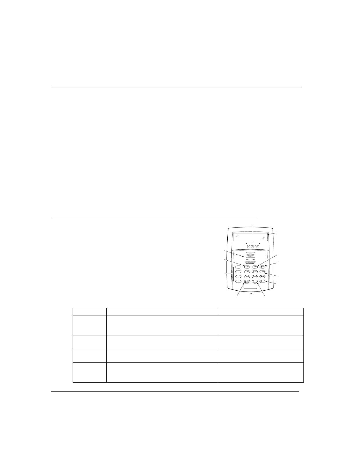
8VLQJWKH9RLFH0HVVDJH&HQWHULI9RLFH.H\SDGLVLQVWDOOHG
The Voice Keypads feature a voice message center
that lets you record and playback one message.
The message can be up to 2.5-minutes long
•
The message remains in the keypad’s memory
•
until a new message is recorded.
The volume control of the message is adjustable.
•
Refer to the procedures below when using the
•
Message Center functions.
SPEAKER
RECORD
FUNCTION
KEYS
KEY
LEDS
ARMED MESSAGEREADY
AWAY1OFF
A
2
VOLUME
RECORD
MAX
TEST
4
B
5
CODE
INSTANT
7
C
8
READY
0
D
STATUS
VOICE
*
FA560
LCD
DISPLAY
VOLUME
KEY
PLAY KEY
AND
UP VOLUME
STAY
3
PLAY
BYPASS
6
9
#
FUNCTION
DOWN
CHIME
VOLUME
FUNCTION
KEY
Message Center Functions
To… Press these keys… Notes…
record a
message
end
recording
play a
message
adjust the
volume
[#] FUNCTION + [0] VOICE + [1] RECORD
[1] RECORD
[#] FUNCTION + [0] VOICE + [3] PLAY
[#] FUNCTION + [0] VOICE + [2] VOLUME keys,
then press volume key [3] ↑ (up) or [6] ↓ (down)
The red MESSAGE LED lights.
Message remains in memory
until a new message is recorded.
The red MESSAGE LED flashes,
indicating message waiting.
The recorded message plays and
the red MESSAGE LED turns off.
Adjusting message volume also
adjusts status volume. Volume
cannot be adjusted while playing.
STATUS
KEY
MICROPHONE
VOICE
KEY
FA560VKP-004-V0
– 7 –
Page 8

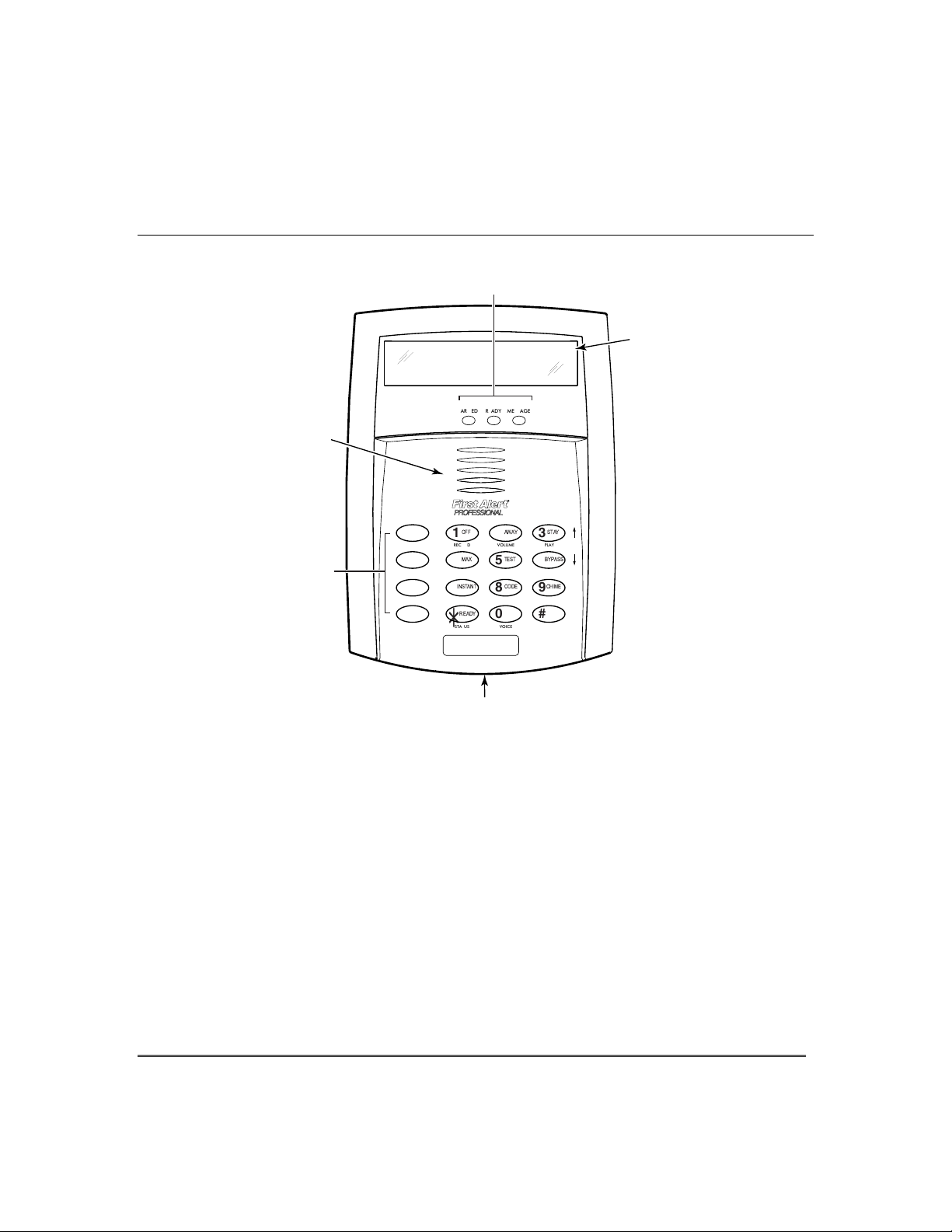
$ERXW7KH.H\SDGV
*HQHUDO,QIRUPDWLRQ
Your keypads allow you to control all system functions. The keypads feature the
following:
•
A telephone style (digital) keypad
•
Liquid Crystal Display (LCD) which shows the nature and location of all
occurrences
•
Built-in sounder which will sound during alarms and troubles. The sounder also
"beeps" during certain system functions and when depressing any of the keys (to
acknowledge the key press).
•
Backlighting of the LCD display windows. Backlighting turns on when any key is
pressed, and when opening an entry/exit door while the system is armed. This
feature is helpful when a keypad is located in a dimly lit area.
IMPORTANT:
that an alarm has occurred during your absence and an intruder may still be on the
premises. LEAVE IMMEDIATELY and CONTACT THE POLICE from a nearby safe
location.
If the keypad beeps rapidly upon entering the premises, it indicates
Your keypads are functionally the same, but may have different types of displays,
depending on the type installed with your system.
Alpha Display
2-line alpha display keypads feature a 2-line, 32-character
alphanumeric LCD which can display system messages in
friendly English. These keypads can also be programmed with
Fixed-Word Display
custom zone descriptors.
Fixed-Word display keypads are functionally identical to Alpha
display keypads, but the LCD display uses pre-designated
Voice Keypads
Voice Keypads (if installed), are functionally the same as other
words to identify the nature and location of occurrences.
keypads, except that these keypads can provide the following:
•
Voice announcements of system status (see Checking for
Open Zones section)
•
Voice chime, which can alert you to the opening of doors and
windows while the system is disarmed (see Voice Chime in
Chime mode section)
•
Message center, which lets you record and playback
messages (see Using the Voice Message Center in the
System Overview section).
– 8 –
Page 9
$ERXW7KH.H\SDGV&RQWLQXHG
ALARM
CHECK
NIGHTFIRE
NOT READY
STAY
INSTANT
BYPASS
NO AC
CHIME
BAT
CANCELED
AWAY
00
)L[HG:RUG'LVSOD\.H\SDG
AWAY:
STAY:
INSTANT:
Lit with STAY = Instant mode
BYPASS:
NOT READY:
NO AC:
AC:
CHIME:
BAT:
ALARM:
CHECK:
FIRE:
NIGHT:
CANCELED:
All burglary zones, interior and
perimeter, are armed.
Perimeter burglary zones, such as
protected windows and doors, are
armed.
Entry delay is turned off:
Lit with AWAY = Maximum mode
This appears when one or more
burglary protection zones have been
bypassed.
Appears when burglary portion of the system is not ready for arming
(due to open protection zones). The system is ready to arm when this
message disappears and the READY indicator light comes on.
Appears when AC power has been cut off. System is operating on
backup battery power.
Appears when AC power is present.
Appears when the CHIME feature is activated.
Low battery condition in a wireless sensor (if zone number displayed)
or low system battery (if no zone number displayed).
Appears when an intrusion has been detected and the system is armed
(also appears during a fire alarm or audible emergency alarm).
Accompanied by the protection zone in alarm.
Appears when a malfunction is discovered in the system at any time or
if an open is detected in a FIRE zone at any time or a fault in a
DAY/NIGHT burglary zone during a disarmed period. Accompanied by
a display of zone number in trouble.
Appears when a fire alarm is present. Accompanied by a display of the
zone in alarm.
A FIRE display also appears when a fire alarm is manually activated,
accompanied by a display of emergency key zone number programmed
for fire.
Appears with “STAY” when the system is armed in Night-Stay mode
(perimeter burglary zones and pre-selected interior zones are armed).
Appears when an
alarm
has been canceled (see Exit Alarm section on
page 13 for more information on canceled alarms and displays).
ALARM
CHECK INSTANT CANCELED
FIRE
FIXED-WORD DISPLAYS
AWAY
BYPASS
STAY
FA260KP
FA215KP
NIGHT NO AC
PHONE TEST
NOT READY
CHIME BAT
– 9 –
Page 10

)XQFWLRQVRIWKH.H\SDGV
NOTE:
keys indicate their primary purpose; the
functions printed under some of the keys (shown
in brackets under the respective key), indicate
their alternate or secondary purpose.
DISPLAY WINDOW
Alpha Display Keypads:
Liquid Crystal Display (LCD) keypads that display
protection point identification, system status, and
messages.
Fixed-Word Display Keypads:
protection zone ID and system status messages using
pre-designated words in the LCD display area.
silences alarms and audible trouble indicators, and
clears visual display after problem's correction.
[RECORD]
with the FUNCTION and VOICE keys to record up to
a 2.5-minute message.
perimeter and interior.
[VOLUME]
with the FUNCTION and desired volume control keys
↑
message or voice system status.
system only. Interior protection is not armed, allowing
movement within premises without causing an alarm.
If pressed twice in succession, arms system in NightStay mode.
[PLAY]
the FUNCTION and VOICE keys to play the recorded
message.
[ ↑ ]
FUNCTION and VOLUME keys to raise the message
and voice system status volume.
perimeter and interior, but without entry delay feature.
Entering via an entry/exit door will cause an alarm.
disarmed. Refer to
procedures.
attributes for other users of the system.
The functions printed directly on the
2-line, 32-character
1 OFF
2 AWAY
[3] or
3 STAY
4 MAXIMUM
5 TEST
8 CODE
Disarms burglary portion of the
On Voice keypads, used in conjunction
Arms the entire burglary system,
On Voice keypads, used in conjunction
[6] to adjust the volume of a recorded
↓
Arms perimeter portion of burglary
On Voice keypads, used in conjunction with
On Voice keypads, used in conjunction with the
Arms the entire burglary system,
Tests the system and alarm sounder if
Testing The System
Used to assign additional user codes and
section for test
Display
system,
6 BYPASS
from being monitored by the system.
[ ↓ ]
FUNCTION and VOLUME keys to lower the message
and voice system status volume.
7 INSTANT
mode, but without the entry delay feature.
9 CHIME
the opening of windows or doors while the system is
disarmed sounds 3 beeps at the keypad(s).
KEYS 0–9:
perform their associated system functions after the
security code has been entered.
∗ READY
[STATUS]:
STATUS key annunciates the current system status.
Pressing the STATUS key a second time annunciates
and displays system and/or zone faults (if they exist).
0 [VOICE]
RECORD, VOLUME and PLAY functions.
# T
system without use of a security code (if programmed).
[FUNCTION]
voice or volume function.
FUNCTION KEYS:
set for certain functions, such as panic (emergency)
functions. For details, see the
ARMED LED INDICATOR:
system has been armed.
READY LED INDICATOR:
the system is ready to be armed (no faults present).
While the system is disarmed, this indicator will go on
and off as protection zones are closed and opened.
MESSAGE LED INDICATOR:
keypads, flashes red when message waiting or lights
red (steady) when in record mode.
MIC
Center recordings.
INTERNAL SPEAKER:
mimics the alarm sounder during alarms, and will
also "beep" during certain system functions. The
speaker also provides voice playback for any recorded
messages.
Removes individual protection zones
On Voice keypads, used in conjunction with the
Arms in manner similar to the STAY
Turns
CHIME mode on and off.
Used to enter your security code(s) and to
Used to display open protection zones.
On Voice keypads, one press of the
On Voice keypads, enables the
his key can be used for "Quick Arming" of the
On Voice keypads, enables the desired
Keys A, B, C, D may have been
Function Keys
(RED) Lit when the
(GREEN) Lit when
(RED) On Voice
On voice keypads, microphone for Message
:
The built-in speaker
When on,
section.
– 10 –
Page 11
)XQFWLRQVRIWKH.H\SDGV&RQWLQXHG
LEDS
LCD
DISPLAY
ARMED MESSAGEREADY
SPEAKER
STAY
AWAY
OFF
1
RECORD
MAX
4
INSTANT
7
READY
STATUS
*
FA560
2
VOLUME
5
8
0
VOICE
TEST
CODE
3
PLAY
BYPASS
6
CHIME
9
#
FUNCTION
FUNCTION
KEYS
A
B
C
D
MICROPHONE
FA560VKP-003-V0
Voice-capable 2-line Alpha keypad
IMPORTANT!
• When entering codes and commands, sequential key depressions must be made
within 4-5 seconds of one another. If 4-5 seconds elapse without a key depression, the
entry will be aborted and must be repeated from its beginning. Be sure to observe
this precaution when performing any of the procedures in this manual.
•
If you make a mistake while entering a security code, stop, press the [
then start over. If you stop in the middle while entering a code, and then
immediately start the entry over, an erroneous code might be entered.
] key, and
✱
– 11 –
Page 12

(QWU\([LW'HOD\V
Your system has preset time delays, known as exit delay and entry delay.
([LW'HOD\
Exit delay gives you time to leave through the designated exit door(s) without setting
off an alarm. Exit delay begins immediately after arming your system in any arming
mode and Alpha Display keypads display the message “You May Exit Now.” When
“You may exit now” disappears, the system is fully armed. If programmed, a slow
beeping will sound during the exit delay period until the last 10 seconds, which then
changes to fast beeping (alerting you to the end of exit delay). If you cannot leave by
this time, you should stop, disarm the system, and start over to avoid a false alarm.
Exit Delay Restart.
arming STAY, you can re-start the exit delay at any time – simply press the [✱]
key, then let that person in. The system automatically re-arms when exit delay
expires, which avoids having to disarm the system and then re-arm it again. In
addition, when the system is armed AWAY, reopening and closing the entry/exit door
before exit delay time expires (e.g., reentering to get a forgotten item) will reset the
exit delay time once.
(QWU\'HOD\
Entry Delays give you time to disarm the system when you re-enter through the
designated entrance door. You must disarm the system (simply enter your security
code) before the entry delay period ends, or an alarm will occur. The keypad beeps
during the entry delay period, reminding you to disarm the system. There are two
entry delays (if programmed). The first is for your primary entrance and the second
can be used for a secondary entrance, where a longer delay is required to walk to the
keypad to disarm the system.
You can also arm the system with no entry delay at all by using the INSTANT or
MAXIMUM arming mode. This mode provides greater security while on the
premises or while away for extended periods of time.
See your installer for your delay times.
Partition 1___________________________________________________________
If you wish to open the entry/exit door to let someone in after
– 12 –
Exit Delay:
seconds Entry Delay 1:
Entry Delay 2:
NOTE:
Entry/Exit times set for partition 1 also apply to the common zone (FA168CPS).
seconds
seconds
Partition 2 (FA168CPS) ______________________________________________
Exit Delay:
seconds Entry Delay 1:
Entry Delay 2:
seconds
seconds
Page 13

([LW$ODUPV
Whenever you arm the system, the exit delay begins. If an entry/exit door or interior
zone is faulted within two minutes after the end of the exit delay (e.g., exit door left
open), the system sounds an alarm and starts the entry delay timer. If you disarm the
system before the entry delay ends, the alarm sound stops and the message
"CANCELED ALARM" or "CA" and zone number is displayed on the keypad. No
message is sent to the Central Station.
To clear the exit alarm condition, make the open zone intact then enter your code
plus OFF.
If you do not disarm the system before the entry delay ends, and an entry/exit door or
interior zone is still open, the alarm sound continues and an "exit alarm" message is
sent to the Central Monitoring Station. The message ""EXIT ALARM" or "EA" and zone
number is displayed on the keypad. To stop the alarm, the system must be disarmed
(your code plus OFF); to clear the display, enter your code plus OFF a second time.
Your system may have been programmed for this feature to minimize false alarms sent to the Central
Monitoring Station. Ask your installer if "Exit Alarm" is active in your system. If so, check this box.
(QWU\([LW'HOD\V
&RQWLQXHG
– 13 –
Page 14
&KHFNLQJ)RU2SHQ=RQHV
8VLQJWKH>∗@.H\
B
efore arming your system, all protected doors, windows and other protection zones
must be closed or bypassed, otherwise the keypad will display a "Not Ready" message.
Use the READY key to display all faulted zones, making it easier for you to identify
and secure any open zone.
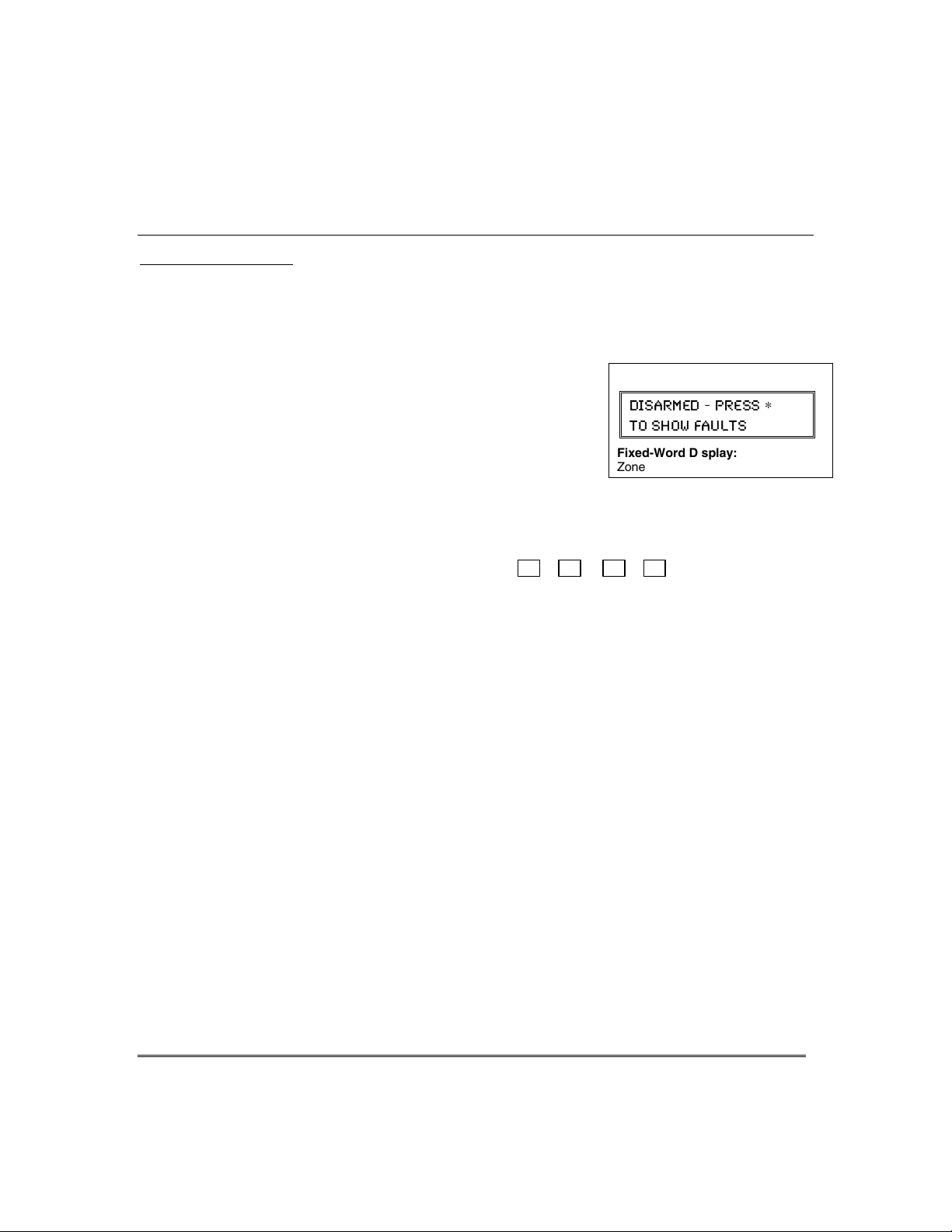
1. Press [∗] (do not enter code first) to display faulted
.
zones
2. Secure or bypass the zones displayed.
3.
The keypad’s READY indicator lights when all
protection zones have been either closed or bypassed.
4. Arm the system as desired.
Voice Status: Voice Keypads (if installed), can announce system status and faulted
zones (up to 3 zone descriptors) if the Voice Status feature is turned on.
To turn the Voice Status feature on/off:
(also turns on Voice Chime mode; see
Chime mode
To announce Status: Press [#] FUNCTION + [0] VOICE + [∗] STATUS key.
(Announces current system status; e.g., “Disarmed Ready to
Arm.”)
To announce faults: Press [#] FUNCTION + [0] VOICE + [∗] STATUS + [∗] again
within 5 seconds of the first press. (Announces up to three
faulted zones with their zone descriptors, if programmed.)
# + 0 + 2 + 4
section)
Alpha Display:
(-7%61)( 46)77
83 7,3; *%9087
Fixed-Word Display:
Zone no. and “NOT READY”
∗
– 14 –
Page 15

$UPLQJWKH6\VWHP
6WD\0RGH$UPV3HULPHWHU2QO\(QWU\'HOD\2Q
•
Used when you want to arm the system with persons staying inside (or if you have
pets that are moving throughout the premises).
•
The perimeter sensors are armed, but interior sensors are left disarmed.
•
Exit delay begins (you can leave through the entry/exit door, if desired).
•
An alarm sounds if any protected window or non-entry/exit door is opened.
•
You may otherwise move freely within the premises.
•
Persons entering later can enter through an entry/exit door, but they must disarm
the system within the entry delay period to avoid sounding an alarm.
1LJKW6WD\0RGH$UPV3HULPHWHU2QO\3OXV6HOHFWHG=RQHV
•
Use Night-Stay mode to provide increased security while staying inside.
•
Arms same as Stay mode, but also arms pre-selected interior sensors (programmed
by your installer), while other interior sensors are left disarmed.
•
Persons entering later can use entry/exit doors but they must disarm the system and
must not violate any of the programmed interior zones to avoid sounding an alarm.
• IMPORTANT:
alarm if anyone enters those areas (e.g., waking in the middle of the night). To avoid sounding an
alarm, you must disarm the system before any activity takes place in those interior zones.
,QVWDQW0RGH$UPV3HULPHWHU2QO\(QWU\'HOD\2II
•
Used when staying inside and do not expect anyone to use an entry/exit door.
•
Arms same as Stay mode.
•
An alarm sounds immediately if any protected perimeter window or any door is
opened, including entry/exit doors.
• IMPORTANT:
care in selecting this mode of arming.
$ZD\0RGH$UPV(QWLUH6\VWHP(QWU\'HOD\2Q
•
Used when nobody will be staying inside (including pets).
•
The entire system (interior and perimeter) is armed.
•
Exit delay begins letting you leave through the entry/exit door.
•
An alarm sounds if a protected window or any door is opened, or if any movement
is detected inside your premises.
•
You can reenter through an entry/exit door, but you must disarm the system within
the entry delay period to avoid sounding an alarm.
0D[LPXP0RGH$UPV(QWLUH6\VWHP(QWU\'HOD\2II
•
Used when leaving the premises for extended periods (e.g., vacation).
•
Arms same as Away mode, but entry delay is off.
•
An alarm sounds same as Away mode, and sounds upon opening entry/exit doors.
When Night-Stay mode is on, the selected interior zones are armed and cause an
Arming in this mode greatly increases the chance of false alarms. Use extreme
– 15 –
Page 16

$UPLQJWKH6\VWHP
$UPLQJ&RPPDQGV
Before arming, close all perimeter doors and windows and make sure the Ready to Arm
message is displayed.
Modes of Arming
Mode Press these keys… Keypad Confirms By…
Stay security code + [3] (STAY)
Night-Stay security code + [3] + [3]
Instant security code + [7] (INSTANT)
Away security code + [2] (AWAY)
Maximum security code + [4] (MAXIMUM)
†
Arming Ding:
arming, if programmed to do so. The ding confirms that the system is armed, and may occur immediately
after the command or be delayed (until arm/disarm report is sent or exit delay expires). Ask your installer
about how this feature is set for your system.
Quick Arming
If "Quick Arming" was programmed by the installer, the
of the security code when arming the system in any of its arming modes (except NightStay). However,
Function Key Arming
For any arming command, a function key may have also been programmed for your
system. If so, you can press and hold the appropriate function key for 2 seconds to arm
the system. See your installer for the designated functions (see
Arming
Refer to the
arming (FA168CPS).
In addition to the keypad beeps, the external sounder emits a short “ding” sound after
the security code must always be used to disarm the system.
section).
Accessing Other Partitions
•
three beeps
•
armed STAY message displayed
•
red ARMED indicator lights
•
three beeps
•
NIGHT-STAY message displayed
•
red ARMED indicator lights
•
three beeps†
•
armed STAY message displayed
•
red ARMED indicator lights
•
also note that entry delay is turned off.
•
two beeps†, or, if programmed, beeping for
duration of exit delay
•
armed AWAY message displayed
•
red ARMED indicator lights
Leave the premises through an entry/exit
door during the exit delay period to avoid
causing an alarm. The keypad beeps rapidly
during the last 10 seconds of the exit delay
to warn you that it is ending.
•
same as Away (described above)
Note that entry delay is turned off.
†
†
[#]
key can be pressed in place
Single Button
section for information on multi-partition
– 16 –
Page 17
6LQJOH%XWWRQ$UPLQJ
321
654
987
#0
READY
INSTANT
MAX
OFF
CODE
AWAY
TEST
CHECK
STAY
BYPASS
A
B
C
D
keypad_keys-00-001-V0
The “A”, “B”, “C”, and/or “D” keys on your keypad may have been programmed for
single-button arming. Note that while it will not be necessary to use a security code
for arming, a security code must always be used to disarm the system.
If Single-Button Arming is programmed:
• A function key has been assigned to a specific type of arming: STAY mode,
Night-STAY mode, AWAY mode, or STEP-ARMING (see Step-Arming
paragraph).
• You DO NOT need to enter your security code before pressing the function key
(but you always need your security code to DISARM the system).
Before arming, close all perimeter doors and windows.
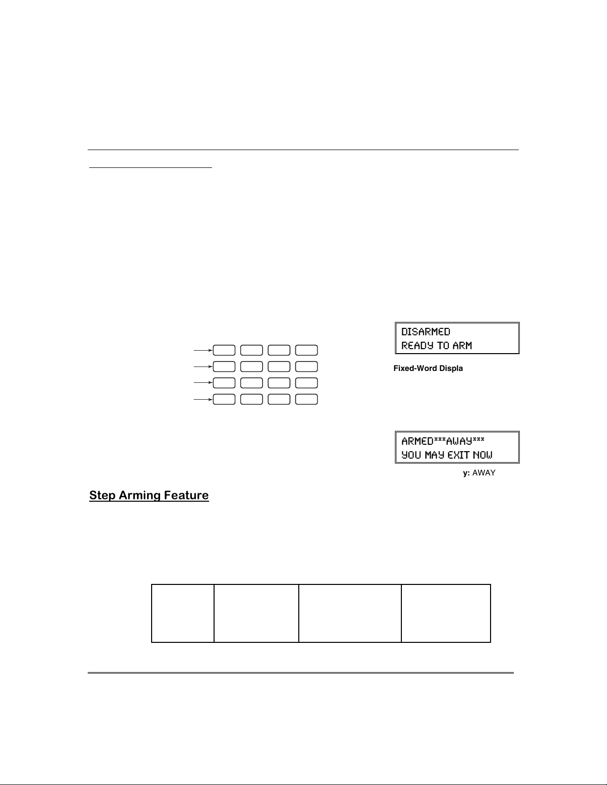
1.
Press and hold the assigned function key for 2
seconds (no code is required). Function keys are
shown below.
$UPLQJWKH6\VWHP
Alpha Display:
(-7%61)(
6)%(= 83 %61
Fixed-Word Display:
READY
2.
The keypad begins beeping and displays the armed
message. The red ARMED indicator also lights.
6WHS$UPLQJ)HDWXUH
Single-Button “Step” arming may have been programmed into one of the lettered keys
(A, B, C, or D). Check with your installer to see if this has been done in your system.
If Step-Arming is programmed:
• The assigned key provides a choice of three levels of security.
• The selected key can be pressed once, twice, or three times, increasing the level
of security with each press, as follows
Key
Ø
A, B, C, D
Alpha Display:
%61)(%;%=
=39 1%= )<-8 23;
Fixed-Word Display:
First Press
Ø
Armed-STAY Armed Night-STAY
Second Press
Ø
(if programmed)
AWAY
Third Press
Ø
Armed-AWAY
– 17 –
Page 18

8VLQJWKH.H\VZLWFK
GREEN
RED
8VLQJWKH.H\VZLWFK
Your system may be equipped with a keyswitch for use when arming and disarming.
Red and green lights on the keyswitch plate indicate the status of your system as
follows:
Green Light: Lights when the system is disarmed and ready to be armed (no
open zones). If the system is disarmed and the green light is off, it
indicates the system is not ready (one or more zones are open).
Red Light: Lights or flashes when system is armed in AWAY or STAY mode.
See your installer for the meanings of the lit red light:
system armed STAY and exit delay has expired
Flashing = system armed STAY and exit delay timer active
Rapid flashing = an alarm has occurred (memory of alarm).
Before arming, close all perimeter doors and windows.
To arm in the AWAY mode:
Turn the key to the right for 1/2 second and release.
Keypads beep twice and the red indicator lights or
flashes.
To arm in the STAY mode:
Turn the key to the right and hold for longer than 1
second, then release. Keypads beep three times and
the red indicator lights or flashes.
To disarm the system:
Turn the key to the right and release. The red light
turns off
Lit Steady = system armed AWAY or
– 18 –
Page 19
8VLQJWKH>2))@NH\
The OFF key is used to disarm the system, silence alarm and trouble sounds, and
clear alarm memories.
IMPORTANT: If you return and the main burglary sounder is on,
CONTACT THE POLICE from a nearby safe location.
If you return after an alarm has occurred and the main sounder has shut itself off,
beep rapidly upon your entering, indicating that an alarm has occurred during your
absence.
LEAVE AT ONCE, and CONTACT THE POLICE from a nearby safe location.
+ 1
1.
(Security Code)
The “READY” indicator light will be lit if all zones
are secure, and the keypad will emit a single tone to
confirm that the system is disarmed.
NOTE: If entry delay has started (you’ve opened the
entry door), you do not need to press the OFF key;
simply enter your security code.
To Silence a Burglary Alarm and Clear a Memory of Alarm
2.
Enter your security code. This disarms the system and silences the alarm (or
warning tones of a Memory of Alarm).
Note the zone in alarm on the keypad display, and make that zone intact (close
door, window, etc.). Now enter the security code plus OFF to clear the keypad’s
Memory of Alarm display.
To Silence a Fire Alarm and Clear Memory of Alarm
3.
Simply press the OFF key to silence the alarm. Then enter the security code plus
OFF sequence to clear the keypad's Memory of Alarm display. See the Fire Alarm
System section.
'LVDUPLQJDQG6LOHQFLQJ$ODUPV
DO NOT ENTER, but
the keypad will
Alpha Display:
OFF
(-7%61)(
6)%(= 83 %61
Fixed-Word Display: READY
– 19 –
Page 20
%\SDVVLQJ3URWHFWLRQ=RQHV
8VLQJWKH%<3$66.H\
Use t
his key when you want to arm your system with one or more zones intentionally
unprotected.
Vent Zones:
automatically bypassed if left open when arming the system (you do not need to
manually bypass them). However, if a vent zone window is closed
becomes protected and will cause an alarm if opened again while the system is armed.
When bypassing zones:
• The system must be disarmed before you can bypass zones.
• Bypassed zones are unprotected and will not cause an alarm if violated.
• The system will not allow fire zones to be bypassed.
• Zones are automatically unbypassed when the system is disarmed.
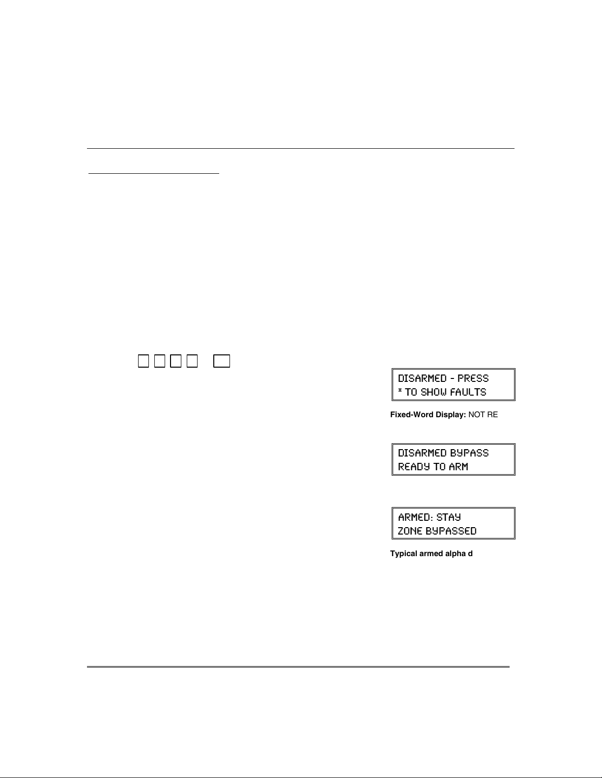
1.
+ 6 + zone numbers (see below)
(Security Code)
Enter the 2-digit zone number(s) for the zone(s) to be
bypassed (e.g., 06, 10, 13, etc.). Single digit zone
numbers must be preceded by a zero (e.g. 05, 06).
2.
When finished, the keypad will momentarily display
a "Bypass" message for each bypassed zone number.
Wait for all bypassed zones to be displayed.
Arm the system as usual. When armed, the arming
message is displayed with “ZONE BYPASSED.”
To display bypassed zones prior to arming, enter
your security code and press the [6] BYPASS key.
Your system may have certain windows set as “vent” zones, which are
BYPASS
after
arming, it
Alpha Display:
(-7%61)( 46)77
83 7,3; *%9087
Fixed-Word Display:
Alpha Display:
NOT READY
(-7%61)( &=4%77
6)%(= 83 %61
Fixed-Word Display:
BYPASS
%61)( 78%=
>32) &=4%77)(
Typical armed alpha display after
bypassing zones.
– 20 –
Page 21

4XLFN%\SDVV
If programmed, "Quick Bypass" allows you to easily bypass all open (faulted) zones
without having to enter zone numbers individually. This feature is useful if, for
example, you routinely leave certain windows open when arming at night.
+ 6 + [#]
1.
(Security Code)
In a few moments, all open zones will be displayed
and automatically bypassed. Make sure that only
those zones that you wish to leave unprotected are
bypassed, and that there are no other zones
unintentionally left open.
Wait for all bypassed zones to be displayed, then arm
2.
the system as desired.
Ask your installer if "Quick Bypass" is active for your
system, and if so, check here:
BYPASS
%\SDVVLQJ3URWHFWLRQ=RQHV
Alpha Display:
(-7%61)( 46)77
83 7,3; *%9087
Fixed-Word Display:
Alpha Display:
NOT READY
(-7%61)( &=4%77
6)%(= 83 %61
Fixed-Word Display: BYPASS
– 21 –
Page 22

&KLPH0RGH
CHIME mode alerts you to the opening of a perimeter door or window while the
system is disarmed. When Chime mode is activated:
• Three tones sound at the keypad whenever a perimeter door or window is opened.
• Interior zones do not produce a tone when they are faulted.
• Pressing the
• Chime mode can be used only while the system is disarmed.
To turn Chime Mode on:
(Security Code)
The CHIME message will appear. Perimeter zones
will cause a tone when faulted.
To turn Chime Mode off:
(Security Code)
Voice Chime: You can set the Voice Keypads (if installed) to announce faulted
(opened) entry/exit or perimeter zones whenever normal Chime mode is on.
To turn Voice Chime Mode on or off:
(normal Chime mode must be on first)
When Voice Chime is on, faulted zones cause a voice status announcement, chime
and display. When off, the sounder still provides chime if normal Chime mode is on.
READY
key will display the open protection points.
+ 9
CHIME
+ 9 again (
CHIME
# + 0 + 2 + 4
Alpha Display:
(-7%61)( ',-1)
6)%(= 83 %61
Fixed-Word Display:
CHIME message disappears)
CHIME
– 22 –
Page 23

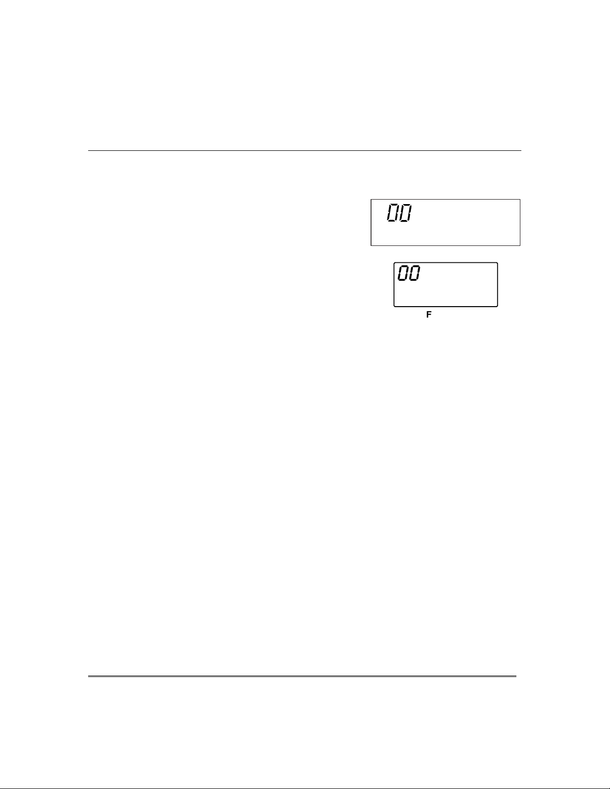
9LHZLQJWKH&XUUHQW'DWHDQG7LPH
The system lets you view its time and date setting on alpha keypad.
+[#] + [6] [3]
'DWHDQG7LPH
Alpha Display:
(Security Code)
OR, press the function key (A, B, C, or D) for viewing
current date and time, if programmed.
A typical time/date display is shown.
The display will remain on for about 30 seconds.
“A ” “ B ” “C ” “D ”
If one of the above keys has been programmed for the date/time
display feature, place a check mark in the box beneath that key.
6HWWLQJWKH'DWHDQG7LPH
You can set the time and date by doing the following:
+[#] + [6] [3]
1.
(Security Code)
2. Press [∗] when the time/date is displayed.
A cursor appears under the first digit of the hour.
To move cursor ahead, press [
• Enter the 2-digit hour setting.
• Enter the 2-digit minute setting.
• Press [1] for PM or [0] for AM.
• Enter the last two digits of the current year.
• Enter the 2-digit month setting.
• Enter the 2-digit day setting.
3. To exit, press [∗] when cursor is at the last digit, or
wait 10 seconds.
∗
]. To go back, press [#].
(-7%61)(
6)%(= 83 %61
8-1)(%8) 7%8
%1C
Alpha Display:
(-7%61)(
6)%(= 83 %61
8-1)(%8) 7%8
41
Current time display
8-1)(%8) 7%8
4
Time/date editing display
– 23 –
Page 24

3DQLF.H\V
8VLQJ3DQLF.H\V
Your system may have been programmed to use special keys to manually activate
emergency (panic) functions as follows:
This Function Sends this signal* With This Sounding…
Silent Alarm silent alarm no audible alarm or change in normal
Audible Alarm audible alarm a loud, steady alarm at keypad(s) and
Personal Alarm auxiliary alarm steady alarm sound at keypad(s), but
Fire Alarm fire alarm temporal (pulsing) sound at external
*All panic functions send signals to the Central Monitoring Station, if connected.
To activate a Panic Function:
Press and hold down for at least 2 seconds whichever
lettered key on the keypad has been programmed for
the desired emergency function.
OR
Press both keys of the assigned key pair at the same
time.
display to indicate that a silent alarm
has been initiated.
at any external sounders that may be
connected.
not at external bells or sirens.
bells and sirens.
Alpha Display:
(-7%61)(
6)%(= 83 %61
Fixed-Word Display:
Typical Panic Alpha Display:
READY
%0%61
– 24 –
A
ZONE 95
B
ZONE 99
C
ZONE 96
D
Lettered Panic Keys Panic Key Pairs
READY
ARMED
R
AWAY
STAY
OFF
AWAY
1
3
2
TEST
MAX
4
INSTANT
7
READY
FA560
BYPASS
6
5
CHIME
CODE
9
8
#
0
560KP-10-001-V0
STAY
PAGE
ZONE 95
Fixed-Word Display:
READY
ARMED
R
AWAY
STAY
OFF
AWAY
1
3
2
TEST
MAX
4
INSTANT
7
READY
FA560
5
CODE
8
0
ZONE
99
BYPASS
6
CHIME
9
#
STAY
PAGE
PRESS BOTH KEYS
OF DESIRED PAIR
AT THE SAME TIME
ZONE 96
99 and ALARM
560KP-10-002-V0
See your installer and use the chart provided in the Features Programmed in Your
System section to note the functions that have been programmed for your system.
Page 25

$ERXW0DFUR.H\V
The “A”, “B”, “C” or “D” keys can be used to automatically activate a series of
commands of up to 16 keystrokes, if programmed for this function. These keystrokes,
as a group, are called “macros” and are stored in the system's memory.
• Typical macro functions can include:
- Arming sequences: STAY, Night-STAY, INSTANT, or AWAY
- Bypassing particular zone(s)
- Activating relay(s) for turning on (or off) lights, fans, etc.
• Up to four (FA168CPS) or two (FA148CP) macros can be assigned – but no
more than one macro to a key.
• Macros can be activated only by users with authority levels authorized to
perform the macro’s function.
NOTE: The installer must activate the desired function key before macros can be
assigned. See the chart at the back of this manual for the key(s) assigned for macros.
+ [#] + [6] + [6]
1.
0DFUR.H\3URJUDPPLQJ8VDJH
Alpha Displays:
(Security Code)
Enter the macro number (1-4 for FA168CPS; 1-2 for
2.
FA148CP) to be programmed at the “Select Macro?”
prompt. Remember, only one macro can be assigned
to each key.
3. If a macro has been previously defined, the
keystrokes are shown on the bottom line of the
display, otherwise the display is blank.
To exit this mode (and keep the existing macro
definition), press any key except the [∗] key. The
system returns to normal mode.
To define a macro for the selected key, press [∗] and
continue with the next prompt.
Enter the first of the series of desired commands, (do
not include your user code), then press/hold the “D”
key for at least two seconds to complete the first
command. This key terminates each command, and
appears as an “F” in the keypad display.
(-7%61)(
6)%(= 83 %61
7)0)'8 1%'63
1%'63 (-740%=
1%'63 4+1
– 25 –
Page 26

0DFUR.H\3URJUDPPLQJ8VDJH
The keypad beeps to acknowledge your input and
displays the command you entered (followed by “F”).
4. Enter the next command, followed by press/holding
the “D” key for at least two seconds. The keypad
beeps and displays the keystrokes entered so far.
5. Repeat until the all the desired commands (up to 16
characters including the “F”s) have been entered.
Be sure to check your keystrokes before continuing.
If you made a mistake, you must start over.
6. To exit, press/hold the “D” key for at least two
seconds. The display returns to system status and
indicates system is ready.
([DPSOHRI0DFUR3URJUDPPLQJ
Suppose you want to (1) bypass the two upstairs window zones, then (2) turn on an
exterior light, and then (3) arm the security system in the AWAY mode. The
procedures in the table that follows show you how you would program this macro:
Function
1.
2.
3.
(device 01).
4.
5.
6.
Bypass zones 02 & 03
Insert terminator.
Turn light on
Insert terminator.
Arm system AWAY
Insert terminator.
Keystrokes Required
Press
2-digit zone numbers 02 & 03.
Press the “D” key for at least 2 seconds.
Press [#] and 7 keys for “device ON”, and
[01] key for selecting device 1.
Press the “D” key for at least 2 seconds.
Press
Press the “D” key for at least 2 seconds.
8VLQJD3URJUDPPHG0DFUR.H\
(-7%61)(
6)%(= 83 %61
)28)6 97)6 '3()
1.
The programmed macro sequence begins
BYPASS [6]
AWAY [2]
key, then
key.
Press the Macro key programmed for the desired
series of commands for at least 2 seconds. The “Enter
User Code” prompt appears. The prompt remains
displayed for up to 10 seconds.
Enter your 4-digit user code.
automatically after the user code is entered.
Typical Macro Alpha Display:
1%'63 4+1
*#**
FRQW
Keypad Display
*
*#
*#*
*#*
*#**
– 26 –
Page 27

$ERXW'HYLFH&RPPDQGV
Your system may be set up so that it can control certain lights or other devices.
• Some devices may be automatically turned on or off by the system.
• You may be able to override automatically controlled devices using the
commands described below.
• Some devices can be manually turned on or off using the commands described
below.
• See your installer for a list of devices that may be set up for your system. A list
of these devices is provided at the back of this manual for you to fill out.
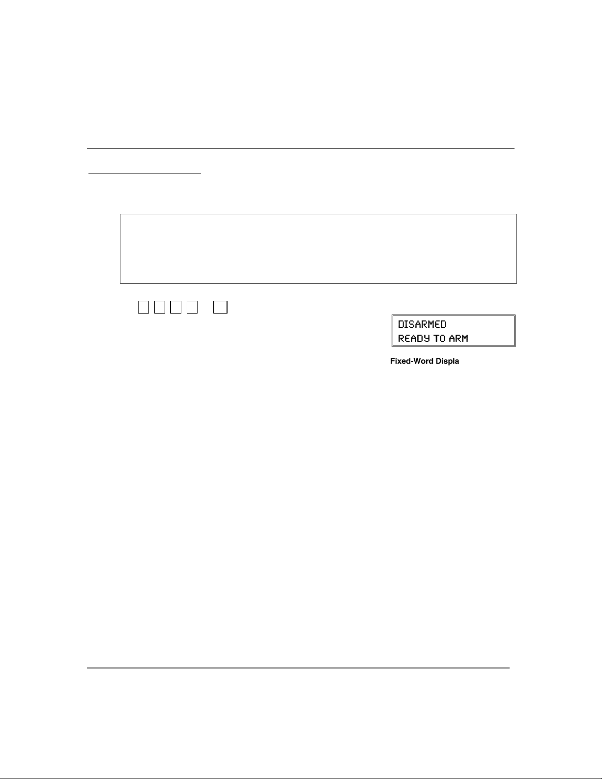
To Activate Devices:
+ [#] + [7] + 2-digit device number
(Security Code)
Devices associated with that device number activate.
To Deactivate Devices:
+ [#] + [8] + 2-digit device number
8VLQJ'HYLFH&RPPDQGV
Alpha Display:
(-7%61)(
6)%(= 83 %61
Fixed-Word Display:
READY
(Security Code)
Devices associated with that device number deactivate.
– 27 –
Page 28

3DJLQJ)HDWXUH
$ERXW$XWRPDWLF3DJLQJ
Your system may be set up to automatically send alert messages to several pagers (up
to four for FA168CPS, up to two for FA148CP) as certain conditions occur in your
system.
•
The following events can be programmed by your installer to be sent to the pagers:
arming and disarming
arming/disarming from a keypad using a security code; auto-arming/disarming,
arming with assigned button, and keyswitch arming do not send pager messages.)
•
You can also program the system to send an automatic pager message to alert you
in the event that someone has not arrived home (disarmed the system) within a
defined period of time (see the
“latch key report”).
•
Your installer programs the pager phone numbers and reporting events.
•
The pager message consists of a 7-digit system status code that indicates the type of
condition that has occurred.
•
An optional, predefined 16-digit character string can precede the 7-digit system
status code; these characters can consist of a PIN no., subscriber account no., or any
additional data that you may wish to have sent to the pager.
•
The pager display format is as follows:
Optional 16 digits
AAAAAAAAAAAAAAAA
ÈÈ
A = B = C =
Optional 16-digits for
Account numbers,
PIN numbers, or any
other data;
programmed by the
installer, if required.
The 3-digit Event Codes (BBB) that can be displayed are:
911 = 811 = 101 = 102 =
Alarms.
The 4-digit number
(CCCC) following this
code is the partition no.
and zone no. that
caused the alarm.
Ex. 1.
³
3-digit Event Code
A 3-digit code that
describes the event
that has occurred
in your system
(see for event
codes table below)
The 4-digit number
(CCCC) following this
code is the partition no.
and zone no. that
= R eporting of an alarm (911) caused by a fault on zone 4 on Partition 1 (1004).
caused the trouble.
†
, alarms, and trouble conditions. († reports when
È
È
BBB
–
Troubles.
Scheduling
CCCC
–
section for details on programming a
1-digit Partition No. + 3-digit Zone No. or User No.
Å
Å
A 1-digit Partition number plus a 3-digit Zone or User
number, depending on the type of event that has
occurred, where:
alarms and troubles display zone number
•
arming/disarming (opens/closes) display user number
•
Open
(system disarmed).
The 4-digit number
(CCCC) that follows
this code is the
partition no. and user
no. that disarmed the
system.
(system armed).
The 4-digit number
(CCCC) that follows
this code is the
partition no. and user
no. that armed the
system.
Close
– 28 –
Ex. 2.
³
= Reporting of a closing–system arming (102)– by user 5 in Partition 2 (2005).
Page 29

0DQXDO3DJLQJ
Your system may be set up so you can manually send a message to up to four
(FA168CPS) or two (FA148CP) pagers.
• Your installer programs the paging function key and the pager phone numbers.
• Pressing the paging keys sends the message
•
This message could mean “call home”, “call your office”, or any other prearranged
meaning.
• See the Paging chart at the back of this manual for details of the paging setup for
your system.
1. Hold
pager key
Press and hold the programmed Paging Key for at
least 2 seconds (wait for beep), then press the pager
number* representing the pager intended to receive
the message.
2. The recipient, on seeing the 999–9999 message, will
understand the prearranged meaning of this signal.
If no number is pressed, the message is sent to pager 1
*
/DWFK.H\3DJLQJ
You can program a schedule that causes a pager report to be sent if the system is not
DISARMED by the scheduled time (see Scheduling section, event “03”). For example,
a working parent might want a message to be sent to a pager if their child did not
arrive home from school and disarm the system by a certain time.
If programmed, the message that is sent is:
3DJLQJ)HDWXUH
999– 9999
2 seconds then press pager no. (1-4).
.
777– 7777
to the selected pager
Alpha Display:
(-7%61)(
6)%(= 83 %61
Fixed-Word Display:
Pager Display
.
READY
.
– 29 –
Page 30

6HFXULW\&RGHV$XWKRULW\/HYHOV
$ERXW6HFXULW\&RGHV
Your installer assigned a master code that is used to perform all system functions.
In addition, you can assign different security codes for use by other users (FA168CPS
provides 47 additional codes; FA148CP provides 31 additional codes).
•
Only the System Master and Partition Master can assign user codes to users.
•
Users are identified by 2-digit user numbers and are pre-assigned to either
partition 1 or partition 2 (FA168CPS).
•
Only the Installer or System Master can change user partitions.
•
In addition to a security code, each user is assigned various system attributes.
•
User codes can be used interchangeably within a partition when performing system
functions (a system armed with one user's code can be disarmed by another user's
code), with the exception of the Guest code and Arm Only code described below.
•
User code programming involves these steps:
1. Choose a user number from the set of users assigned to the partition in which
the user will be operating, and assign a 4-digit security code.
2. Assign an authority level to that user.
3. Assign other attributes as necessary (see attributes on the next page).
NOTE:
Therefore, the only step you usually need to do when adding users is assign a user
number (from the partition’s pre-assigned user numbers) and a security code.
$XWKRULW\/HYHO'HILQLWLRQV
Authority levels define the system functions a particular user can/cannot perform.
Level Title Explanation
N/A System Master Reserved for user 02; Can perform all system functions and assign codes in
0 Standard User Can only perform security functions in assigned partition.
1 Arm Only Can only arm the system. Cannot disarm or do other functions.
2 Guest Can arm the system in assigned partitions, but cannot disarm the system
3 Duress Code Intended for use when you are forced to disarm or arm the system under
4 Partition Master (FA168CPS) Can do everything a standard user can do, and
The factory settings are designed to meet most normal user situations.
(default = 1234)
both partitions; can change its own code as follows:
Master code + [8] + 02
Cannot perform other system functions.
the system was armed with this code. This code is typically assigned to
unless
someone (e.g., babysitter or cleaner) who has a need to arm/disarm the system
only at certain times. The user of this code should
feature.
threat. When used, the system will act normally, but can silently notify the
Central Monitoring Station of your situation, if that service has been provided.
can assign user codes to users in their partition.
new master code + new master code again
+
not
use the “Quick Arming”
– 30 –
Page 31

6HFXULW\&RGHV$XWKRULW\/HYHOV
+RZWR$VVLJQ8VHU&RGHVDQG$WWULEXWHV
The following lists the various command strings for adding user codes and attributes.
Refer to the User Setup chart at the back of this manual for factory
assignments of user attributes and to keep a record of user programming.
NOTE: Partition Master codes (FA168CPS only) apply only to those user numbers
previously assigned (by the system master/installer) to the partition master’s partition.
Add User Code:
Users 03/33 are preset
(
to partition programmers,
but can be changed.)
Delete User Code:
Authority Level:
Factory Assignments:
users 04-32/34-49 = 0
users 03/33 = 4
2 = guest
0 = standard user 3 = duress
Access Group:
Factory Assignments: none
User’s Partition:
(FA168CPS only)
Factory Assignments:
Part. 1 = users 03-32
Part. 2 = users 33-49
Partition Entries: 1 = partition 1 and common
2 = partition 2 and common
3 = common partition only
than one, enter partition numbers sequentially, then press [#] to end.
E.g., master code + [8] + [user no.] + [#] [3] + [0] + [1] [2] + [#] gives
the user access to partitions 1 and 2 and the common partition.
RF User Number:
Factory Assignments: none
Z
Pager On/Off:
Factory Assignments:
users 01-49 = 1 (on)
Paging On/Off: 1 = allow paging; 0 = no paging for this user
whenever this code is used to arm or disarm the system.
System/Partition Master code + [8] + user no.
User 01 = installer User 03 = partition 1 master
User 02 = master User 33 = partition 2 master
The Keypad beeps once to confirm that new user was added.
System/Partition Master code + [8] + [user no.] + [#] [0]
The user code and all attributes* programmed for this user number,
including any associated RF keys, are erased from the system.
(*except assigned partition)
System/Partition Master code + [8] + [user no.] + [#] [1]+ auth. level
Authority Levels (see definitions on previous page):
1 = arm only 4 = partition master (FA168CPS only)
System/Partition Master Code + [8] + [user no.] + [#] [2]+ group (1-8)
You can assign users to a group, then set an access schedule that
defines the times this group of users can operate the system. The
system ignores these users outside the scheduled times.
System Master Code + [8] + [user no.] + [#] [3] + [0] + partition(s) + [#]
This command assigns the partitions the user can access. If more
Master/Part. Prog. Code + [8] + [user no.] + [#] [4]+ zone no.
Use this command to assign a wireless button device (keyfob) to this
user (keyfob must be enrolled in system first; see installer).
one number: enter the zone number assigned to a button on the
keyfob that will be used for arming/disarming by this user.
Master/Part. Prog. Code + [8] + [user no.] + [#] [5] + 0 or 1
Y
ou can program a user so that a message is sent to a pager
&RQW
new user’s code
+
– 31 –
Page 32

$FFHVVLQJ2WKHU3DUWLWLRQV
)$&36
*272&RPPDQGDQG0XOWL3DUWLWLRQ$UPLQJ
$ERXW$FFHVVLQJ3DUWLWLRQV
Each keypad is assigned a default partition for display purposes, and will show only
that partition's information.
• If the user is authorized, a keypad in one partition can be used to perform
system functions in the other partition by using the
GOTO
the GOTO section.
• If the user is authorized, that user can arm other partitions. Refer to the MultiPartition Arming section.
The following table shows the relationship of the keypads in each partition when
system is armed and disarmed.
PARTITION 1 PARTITION 2
COMMON ZONE
(LOBBY, etc.)
command. Refer to
Condition 1
Condition 2
Condition 3
Condition 4
Arming
State
Disarmed Partition 1
Ö
Disarmed Partition 1 and
Ö
Armed Partition 1
Ö
Armed Partition 1
Ö
Keypad
Status
Only
Common Zone
Only
Only
Arming
State
Disarmed Partition 2
Armed Partition 2
Disarmed Partition 2 and
Armed Partition 2
Keypad
Status
Only
Only
Common Zone
Only
Arming
State
Disarmed Common Zone
Disarmed Common Zone
Disarmed Common Zone
Armed Common Zone
Keypad
Status
Only
Only
Only
Only
When both partitions are disarmed, the keypad in each partition displays zone
status for its partition only. The common zone keypad shows the status in that
zone only. See Condition 1 above.
When partition 1 is disarmed and partition 2 is armed, the keypad in partition 1
shows the status of partition 1
status of partition 2
See Condition 2 above.
only.
the common zone. Partition 2 will display the
and
When partition 1 is armed and partition 2 is disarmed, the keypad in partition 1
shows the status of partition 1
2
the common zone. See Condition 3 above.
and
. Partition 2 will display the status of partition
only
As long as any one of the two partitions is disarmed, the common zone will always
be disarmed. The common zone will be armed only when both partition 1 and 2 are
armed. See Condition 4 above.
– 32 –
Page 33

$FFHVVLQJ2WKHU3DUWLWLRQV
8VLQJWKH*R7R&RPPDQG
If the user is authorized, a keypad in one partition can be used to perform system
functions in the other partition by using the
• You must use an Alpha keypad to access another partition.
• Keypads automatically return to their original partition after 2 minutes with
no keypad activity.
+ [∗] + partition number (0,1,2,3)
1.
(Security Code)
0 = return to keypad’s original partition.
1 = partition 1; 2 = partition 2; 3 = common zone
The keypad beeps to confirm the partition change.
The keypad remains in the new partition until
2.
directed to go to another partition, or until it
automatically returns to the original partition.
The active partition number is displayed in the upper
left portion of screen, if the option is programmed.
0XOWL3DUWLWLRQ$UPLQJ
Some users can be given Multi-Partition arming ability by being assigned to both
partitions when programming user attributes.
When attempting to arm multi-partitions:
• You must use an Alpha keypad.
• The system arms only if all partitions are “ready to arm.”
• If any partition is “not ready,” the system does not arm at all.
• You can use the GOTO command to bypass open zones before arming.
• If any partition is already armed when global arming is attempted, that
partition remains in its existing armed state.
+ [0] + arm command (see list below)
GOTO
command.
Alpha Display:
(-7%61)(
6)%(= 83 %61
Fixed-Word Display:
Alpha Display:
(-7%61)(
6)%(= 83 %61
Fixed-Word Display:
Alpha Display:
&RQWLQXHG
Green LED lit
Green LED lit
(Security Code)
Multi-Partition Arming Commands
2 = arms all partitions AWAY
3 = arms all partitions STAY
(-7%61)(
6)%(= 83 %61
Fixed-Word Display:
Green LED lit
33 = arms all partitions NIGHT-STAY
4 = arms all partitions MAXIMUM
7 = arms all partitions INSTANT
1 = disarms all partitions
– 33 –
Page 34

$FFHVVLQJ2WKHU3DUWLWLRQV
&RPPRQ=RQH2SHUDWLRQ
&RQWLQXHG
Ask your installer if a
"common zone" was
assigned. If so, check
this box
Your system may have been set up to use a common zone, which is
an area shared by users of both partitions, such as a foyer or lobby.
If so, please note the following:
•
The common zone will sound and report alarms only when both
partitions are armed. If only one partition is armed, the system
ignores faults on the common zone.
•
Either partition may arm its system if the common zone is
faulted, but once armed, the other partition will not be able to
arm unless the common zone is first bypassed or the fault is
corrected.
•
Faults on the common zone are displayed on common partition
keypads, and will also appear on another partition’s keypad when
the alternate partition is armed.
•
Either partition can clear and restore the common zone after an
alarm.
•
Entry/exit time for the common zone is the same as for partition 1.
– 34 –
Page 35

$ERXW6FKHGXOLQJ
The system provides end-user schedules (programmable by master/installer only),
which can control various types of events.
•
Each schedule causes a defined event to start and stop (when appropriate) at a
specified time.
•
Schedules can be set to automatically repeat at various intervals.
•
Schedules can be set for random starting, if desired.
•
FA168CPS provides up to 16 user schedules; FA148CP provides up to 4 user schedules.
&UHDWLQJ6FKHGXOHV
6FKHGXOLQJ
1.
+ [#] + [6] [4]
(Master Code)
2.
Enter a 2-digit schedule number from:
01-16 (FA168CPS) or 01-04 (FA148CP).
Press [∗] to continue.
Enter the desired 2-digit event number from the
3.
following list.
Alpha Displays:
(-7%61)(
6)%(= 83 %61
)28)6 7',)( 23
=59-8
)28)6 ):)28
00 = clear the scheduled event
01 = turn a programmed output on or off
(see Using Device Commands section for a list of output device numbers used
in your system)
02 = set a user access schedule for one or more users
(see Security Codes section for an explanation of access groups)
03 = send a “latch-key” report to a pager if the system is not disarmed by a specified
time; message sent is “777-7777.”
04 = automatically arm the system in STAY mode at a specified time
05 = automatically arm the system in AWAY mode at a specified time
06 = automatically disarm the system at a specified time
07 = Display the word “REMINDER” at a specified time
(if selected, the keypad will beep every 30 seconds beginning when the word
“REMINDER” is scheduled to display. To stop the beeps and cancel the
display once it starts, simply press any key.
Press [∗] to continue.
4. For event number “01,” enter the output number
associated with this schedule.
Otherwise, this prompt is skipped.
Press [∗] to continue to the “Start” prompt below.
():-') 291&)6
<<
– 35 –
Page 36

6FKHGXOLQJFRQWLQXHG
5. For event number “02,” enter the access group
number. Otherwise, this prompt is skipped.
Press [∗] to continue to the “Start” prompt below.
6. For event numbers “03-07,” enter the partition
number to be armed or disarmed.
0 = arm all; 1 = partition 1; 2 = partition 2;
3 = arm common
Otherwise, this prompt is skipped.
Press [∗] to continue to the “Start” prompt.
7. Enter the event’s start time and days of week.
Hour = 00-12; minute = 00-59
AM = 0; PM = 1
Days = Position the cursor under the desired days
using the [∗] key to move forward, then press “1” to
select the day.
Press [∗] to continue.
8. If applicable, enter the event’s stop time and days of
week (applies only to event numbers 01, 02, and 03).
Refer to step 7 for available entries.
Press [∗] to continue.
9. Enter the desired repeat option.
0 = no repeat
1 = repeat schedule weekly
2 = repeat schedule biweekly (every other week)
3 = repeat schedule every third week
4 = repeat schedule every fourth week
e.g., To make a schedule that happens everyday you
would select all days with a repeat count of 1. To
make a schedule that runs for one week then stops,
select everyday with a repeat count of 0.
Press [∗] to continue.
10. For event number 01 (output on/off), select the
desired randomize option. 0 = no; 1 = yes
If selected, the schedule times will vary within 60
minutes of the “hour” time. For example, if a
schedule is set to start at 6:15pm, it will do so the
first time 6:15pm arrives, but on subsequent days it
will start anytime between 6:00 and 6:59 p.m.
Press [∗] to continue.
+6394 291&)6
<
4%68-8-32
78%68 718;8*7
,,11%1
7834 718;8*7
,,11%1
6)4)%8 348-32
<
6%2(31->)
=23 ==)7 <
<
– 36 –
Page 37

$ERXW(YHQW/RJJLQJ
The system records various events in a history log, which can be viewed by the master
user using an Alpha Display keypad.
•
The Event Log holds up to 100 (FA168CPS) or 50 (FA148CP) events.
•
Events are displayed in chronological order, from most recent to oldest.
•
When the log is full, the oldest event is replaced by the logging of any new event.
9LHZLQJWKH(YHQW/RJ
(YHQW/RJJLQJ3URFHGXUHV
1.
+ [#] + 6 + 0
(Master Code)
2. The system displays the most recent event as follows:
event number, type of event (see table of codes below),
zone or user number (depending on type of event)
partition in which event occurred, time and date of
the event’s occurrence.
3. Pressing [∗] displays previous events (back in time).
Pressing [#] displays events forward in time.
4. Exit by pressing any key other than [∗] or [#].
8QGHUVWDQGLQJWKH7\SHRI(YHQW'LVSOD\HG
If the event code is preceded by an E (as in the above display), it means that the
event is new and ongoing; if preceded by an R, it means the event has been restored.
Code - Definition
110 - Fire Alarm
121 - Duress
122 - Alarm, 24-hour Silent
123 - Alarm, 24-hour Audible 309 - Battery Test Failure
131 - Alarm, Perimeter
132 - Alarm, Interior
134 - Alarm, Entry/Exit
135 - Alarm, Day/Night
143 - Alarm, Expansion Module 351 - Telco Line Fault
145 - ECP Module cover tamper 353 - Long Range Radio Trble 407 - Remote Arm/Disarm
146 - Silent Burglary
150 - Alarm, 24-Hr Aux/Mon zn 374 - Exit Error Alarm
162 - Carbon Monoxide
See your installer for more detailed information regarding the meanings of these codes
-
Code
301 - AC Power
Definition
302 - Low System Battery/Batt
Test Fail
305 - System Reset (Log only) 382 - Supervsn Aux Wire Zone 570 - Bypass
321 - Bell/Siren Trouble
333 - Trble, Exp. Mod. Supervsn 393 - Clean Me
341 - Trble, ECP Cover Tamper 401 - Disarmed, Armed AWAY,
344 - RF Receiver Jam
373 - Fire Loop Trouble
-
Code
Definition
380 - Global Trouble, Trouble
Day/Night
381 - RF Supervision Trouble 442 - Keyswitch Arm/Disarm STAY
383 - RF Sensor Tamper
384 - RF Sensor Low-battery 602 - Periodic Test
Armed STAY
403 - Sched. Arm/Disarm
AWAY
406 - Cancel by User
408 - Quick Arm AWAY
409 - Keyswitch Arm/Disarm
AWAY
Alpha Displays:
(-7%61)(
6)%(= 83 %61
) 9 4
%1
-
Code
Definition
441 - Disarm/Arm/ Quick-Arm
STAY/INSTANT
601 - Manual Triggered Dialer Test
606 - AAV to Follow
607 - Walk Test Entered/Exited
623 - Event Log 80% Full
625 - Real-Time Clock was Changed
(log only)
627 - Program Mode Entry (log
only)
628 - Program Mode Exit (log only)
750 -789 - Configurable Zone Type
report codes
– 37 –
Page 38

7HVWLQJWKH6\VWHP
$ERXW7HVWLQJWKH6\VWHP
Test mode allows each protection point to be checked for proper operation.
• The keypad sounds a single beep every 40 seconds as a reminder that the
system is in the Test mode.
• Alarm messages are not sent to your Central Station while Test mode is on.
1
Disarm the system and close all protected windows,
doors, etc. The READY indicator light should come
on if all zones are intact (i.e., all protected windows,
doors, etc. are closed.
2.
+ 5 then [0] (walk)
(Security Code)
The Dial test (option “1”) is intended for the installer
and should not be used unless directed to do so by
your Security System Representative.
3. Listen. The external sounder should sound for 1
second and then turn off. If the sounder does not
sound, CALL FOR SERVICE.
4. Fault zones. Open each protected door and window in turn and listen for three
beeps from the keypad. Identification (zone number or zone description) of each
faulted protection point should appear on the display. The display clears when the
door or window is closed.
5. Walk in front of any interior motion detectors (if used) and listen for three beeps.
The identification of the detector should appear on the display when it is activated.
The display clears when no motion is detected.
Note that if wireless motion detectors are used, there is a 3-minute delay between
activations. This is to conserve battery life.
6. Test all smoke detectors, following the manufacturer's instructions. The
identification of each detector should appear on the display when each is activated.
If a problem is experienced with any protection point (no confirming sounds, no
display), call for service immediately.
When all protection points have been checked and are intact (closed), there should
be no zone identification numbers displayed on the keypad.
TEST
7R%H&RQGXFWHG:HHNO\
Alpha Displays:
(-7%61)(
6)%(= 83 %61
=(-%0 =;%0/
8)78 -2 463+6)77
– 38 –
7. Exit test mode:
+ [1]
(Security Code)
If the test mode is inadvertently left active, it automatically turns off after 4 hours.
During the final five minutes, the keypad will emit a double beep every 30 seconds.
Page 39

CHECK
"Check" and
"Battery" Displays
* Not all systems
use wireless
sensors.
FIXED-WORD DISPLAY KEYPAD
7URXEOH&RQGLWLRQV
T
he word
"beeping" at the keypad, indicates a trouble condition in the system.
To silence the beeping for these conditions, press any key.
A display of "CHECK" and one or more zone numbers
1.
indicates that a problem exists with the displayed zone(s) and
requires your attention. Determine if the zone(s) displayed are
intact and make them so if they are not. If the problem has been
corrected, the display can be cleared if you enter the OFF
sequence (security code plus OFF key) twice. If the display
persists, CALL FOR SERVICE
Note:
indicates that the wiring connection to the external sounder is
at fault (opened or shorted), and you should CALL FOR
SERVICE. See “BELL FAILURE” on next page. A display of
CHECK 90
operation of wireless sensors* in the system. See “
on next page.
If there are wireless sensors* in your system,
2.
condition may also be caused by some change in the
environment that prevents the wireless receiver from receiving
messages from a particular sensor. CALL FOR SERVICE if this
occurs.
IF YOU CANNOT CORRECT A "CHECK" DISPLAY,
CALL FOR SERVICE
06
CHECK
on the keypad's display, accompanied by a
.
A display of
CHECK 70
on Alpha Display keypads
indicates that RF interference may be impeding the
Rcvr Jam
the
.
TYPICAL "CHECK" DISPLAYS
AC
',)'/
&)(6331 ;-2(3;
ALPHA DISPLAY KEYPAD
”
CHECK
– 39 –
Page 40

7URXEOH&RQGLWLRQV&RQWLQXHG
g
Words or letters in parentheses ( ) are those that are
displayed on Alpha Display keypads.
Other Trouble
Displays
*
Any “beeping” that
accompanies a trouble
display can be stopped
by depressing any key
on the keypad or by
entering an OFF
sequence (code + OFF)
**
Not all systems use
wireless sensors.
COMM. FAILURE
(or FC) the telephone communication portion of
SYSTEM LO BAT
(or
with no condition exists. Display is
BAT
zone No.) accompanied by "beeping"* at the
LO BAT
zone descriptor condition in the wireless transmitter**
+
(or
Indicates that there is a low battery
with number displayed (00 is RF keypad).
BAT
zone No.) Accompanied by a single "beep"* (about
Either replace the battery yourself, or
Rcvr Jam
(or
CHECK 90
Wireless part of the system is experiencin
ALARM 1xx
FAULT 1xx
CHECK 1xx
(or 91)
MODEM COMM
(or CC)
BELL FAILURE
(or
CHECK 70
Indicates that a failure has occurred in
your system. CALL FOR SERVICE.
Indicates that a low system battery
keypad. If this condition persists for
more than one day (with AC present),
CALL FOR SERVICE.
once every 40 seconds) at the keypad.
CALL FOR SERVICE. If the battery is
not replaced within 30 days, a
display may occur.
) RF interference which may impede
reception from wireless sensors.**
Indicates a communication problem
between the control and a connected
device (e.g., RF receiver, zone expander)
where the “xx” indicates the device
address. CALL FOR SERVICE.
Indicates that the control is on-line with
the Central Monitoring Station's remote
computer.
The control will not operate while on-line.
Wait a few minutes — the display should
disappear.
Indicates that the wiring connection to
) the external sounder is at fault (open or
shorted). Accompanied by “beeping” at
the keypad. CALL FOR SERVICE.
CHECK
– 40 –
Page 41

Other Trouble
Displays
(Continued)
Total Power Failure
7URXEOH&RQGLWLRQV&RQWLQXHG
AC LOSS
NO AC
(or
check circuit breakers and fuses and
Busy-Standby
(or dI)
OPEN CIRCUIT
(or OC) the control. CALL FOR SERVICE.
Long Rng Trbl
(or bF) Range Radio communication has failed.
CALL FOR SERVICE.
TELCO FAULT
CHECK 94
(or
If there is no keypad display at all, and the READY indicator
is not lit,
system has stopped and the system is inoperative.
SERVICE.
The system is operating on battery power
)
only due to an AC power failure.
If only some lights are out on the premises,
reset or replace as necessary.
If AC power cannot be restored and a
“low system battery” message appears
(see previous page),
SERVICE
.
CALL FOR
If this message remains displayed for more
than 1 minute, system is disabled.
FOR SERVICE
.
CALL
The keypad is not receiving signals from
If part of your system, back-up Long
The telephone line has a problem.
) CALL FOR SERVICE.
operating power (from AC and back-up battery) for the
CALL FOR
In The Event Of Telephone Operational Problems
In the event of telephone operational problems, disconnect the control from the phone line by
removing the plug from the phone wall jack. We recommend that your installer demonstrate this
disconnection on installation of the system. Do not attempt to disconnect the phone connection
inside the control. Doing so will result in the loss of your phone lines. If the regular phones work
correctly after the control has been disconnected from the phone wall jack, the control has a
problem and you should immediately call for service. If upon disconnection of the control, there is
still a problem on the phone line, notify the Telephone Company that they have a problem and
request prompt phone repair service. The user may not under any circumstances attempt any
service or repairs to the security system. Repairs must be made only by authorized service (see
the LIMITED WARRANTY statement for information on how to obtain service).
– 41 –
Page 42

0DLQWDLQLQJ<RXU6\VWHP
Taking Care of
Your System
Silencing Low
Battery Warning
Tones at the
Keypad
Replacing
Batteries in
Wireless Sensors
Wireless sensors
may not have
been used in your
security system
IMPORTANT:
Use only batteries
recommended by
your installer as
replacement.
Routine Care
The components of your security system are designed to be as
maintenance-free as possible. However, to make sure that your system
is in reliable working condition, do the following:
1. Test your system weekly
2. Test your system after any alarm occurs.
.
You can silence the keypad’s warning tones by pressing the OFF key,
but the keypad's low battery message display will remain on as a
reminder that you have a low battery condition in one or more of your
wireless sensors. When you replace the weak battery with a fresh one,
the sensor sends a "good battery" signal to the control as soon as the
sensor is activated (opening/closing of door, window, etc.), causing the
low battery display to turn off. If the sensor is not activated, the display
will automatically clear within approximately 1 hour.
Each wireless sensor in your system has a 9-volt or 3-volt battery. The
system detects a low battery in wireless sensors, including smoke
detectors, the personal emergency transmitter, and the portable
wireless keypad and displays a low battery message*. (A low battery in
a portable wireless keypad is detected as soon as one of its keys is
pressed, and displayed as 00.). Battery-operated smoke detectors with
a low battery also emit a single "chirp" sound approximately once
every 20–30 seconds.
Alkaline batteries provide a minimum of 1 year of operation, and in
most units and applications, provide 2–4 years of service. 3-volt lithium
batteries provide up to 4 or more years of operation. Actual battery life
will depend on the environment in which the sensor is used, the
number of signals that the transmitter in the sensor has had to send,
and the specific type of sensor. Factors such as humidity, high or low
temperatures or large swings in temperature, may all lead to the
reduction of actual battery life in an installation.
*
The low battery message comes on as a warning that battery replacement
in indicated sensor(s) is due within 30 days. In the meantime, a sensor
causing a low battery indication is still fully operational.
• Treat the components of your security system as you would any other
electrical equipment. Do not slam sensor-protected doors or windows.
• Keep dust from accumulating on the keypad and all protective
sensors, particularly on motion sensors and smoke detectors.
• The keypad and sensors should be cleaned carefully with a dry soft
cloth. Do not spray water or any other fluid on the units.
– 42 –
Page 43

)LUH$ODUP6\VWHP,I,QVWDOOHG
THIS SECTION APPLIES ONLY TO RESIDENTIAL SYSTEMS
General
Silencing
Fire Alarms and
Clearing Memory
of Alarm
Your fire alarm system (if installed) is on 24 hours a day, for
continuous protection. In the event of an emergency, the strategically
located smoke and heat detectors will sound their alarms and
automatically send signals to your system, triggering a loud,
interrupted pulsed sound* from the Keypad(s) and any external
sounders. A FIRE message will appear at your Keypad and remain on
until you silence the alarm (see below for silencing fire alarms).
Temporal pulse sounding is produced for Fire alarms, as follows:
*
3 pulses–pause–3 pulses–pause–3 pulses–pause. . . , repeated.
TYPICAL FIRE EMERGENCY DISPLAYS
*-6) 1%78)6
&)(6331
ALPHA DISPLAY KEYPAD
ALARM
FIRE
FIXED-WORD KEYPAD
1. You can silence the alarm at any time by pressing the
security code is not needed to silence fire alarms). To clear the
display, enter your code and press the
key again (to clear
OFF
Memory of Alarm).
2. If the Keypad's FIRE display does not clear after the second OFF
sequence, smoke detectors may still be responding to smoke or heat
producing objects in their vicinity. Investigate, and should this be
the case, eliminate the source of heat or smoke.
OFF
AC
key (the
Smoke Detector
Reset
3. If this does not remedy the problem, there may still be smoke in the
detector. Clear it by fanning the detector for about 30 seconds.
When the problem has been corrected, clear the display by
entering your code and pressing the
OFF
key.
Depending on the type of smoke detectors in your system, it may be
necessary to "reset" the smoke detectors after a fire alarm has been
turned off. Check with your installer. This "reset" is accomplished at a
keypad, as follows:
Enter User Code*, then press the [1] key (* except “arm only” user).
– 43 –
Page 44

)LUH$ODUP6\VWHP&RQWLQXHG
THIS SECTION APPLIES ONLY TO RESIDENTIAL SYSTEMS
Manually
Initiating
a Fire Alarm
Using the Panic
Key(s) Assigned
for FIRE
Emergency
1. Should you become aware of a fire emergency before your smoke or
heat detectors sense the problem, go to your nearest keypad and
manually initiate an alarm by pressing the panic key assigned for
FIRE emergency for 2 seconds. If a key pair has been assigned for
fire, press both keys at the same time. See the
Using the Panic Keys
section below for further details.
2. Evacuate all occupants from the premises.
3. If flames and/or smoke are present, leave the premises and notify
your local Fire Department immediately.
4. If no flames or smoke are apparent, investigate the cause of the
alarm. The zone number(s) of the zone(s) in an alarm condition will
be displayed at the keypad.
A key or key pair may have been assigned for manually initiating a
FIRE alarm. See the
Panic Keys
section for key assignments.
For convenience, indicate the key or key pair assigned for fire below.
Individual Keys
A B C
Press
seconds.
OR
Key Pairs
1
OFF
the individual key assigned for fire
and
∗
READY
for 2
∗
READY
3
STAY
DISPLAYS FOLLOWING MANUAL INITIATION OF A FIRE ALARM
and
and
*-6)
ALPHA DISPLAY KEYPAD
#
#
Press
the key pair assigned
for fire
at the same time.
ALARM
FIXED-WORD KEYPAD
AC
– 44 –
Page 45

)LUH$ODUP6\VWHP&RQWLQXHG
THIS SECTION APPLIES ONLY TO RESIDENTIAL SYSTEMS
1DWLRQDO)LUH3URWHFWLRQ$VVRFLDWLRQ
With regard to the number and placement of smoke/heat detectors, we
subscribe to the recommendations contained in the National Fire Protection
Association's National Fire Alarm Code (NFPA 72) noted below.
Early warning fire detection is best achieved by the installation of fire
detection equipment in all rooms and areas of the household as follows: A
smoke detector installed outside of each separate sleeping area, in the
immediate vicinity of the bedrooms and on each additional story of the
family living unit, including basements and excluding crawl spaces and
unfinished attics.
In addition, the NFPA recommends that you install heat or smoke detectors
in the living room, dining room, bedroom(s), kitchen, hallway(s), attic,
furnace room, utility and storage rooms, basements and attached garages.
KITCHEN
✪
DINING
✪
LIVING ROOM
▲
✪
BEDROOM
■
✪
BEDROOM
✪
BEDROOM
✪
TV ROOM
BEDROOM
KITCHEN
LIVING ROOM
■
▲
✪✪
BDRM
DINING
■
BDRM
✪
✪
✪
5HFRPPHQGDWLRQVRQ6PRNH'HWHFWRUV
BEDROOM
✪
BEDROOM
■
LVNG RM
BASEMENT
▲
■
■
TO
BR
✪
BEDROOM
▲
KTCHN
■
CLOSED
.
DOOR
Smoke Detectors for Minimum Protection
■
Smoke Detectors for Additional Protection
✪
Heat-Activated Detectors
▲
▲
GARAGE
– 45 –
Page 46

)LUH$ODUP6\VWHP&RQWLQXHG
THIS SECTION APPLIES ONLY TO RESIDENTIAL SYSTEMS
(PHUJHQF\(YDFXDWLRQ
CLOSET
PORCH
BEDROOM
KITCHEN
BACK DOOR
BEDROOM
•
BEDROOM
BATH
ND
2 FLOOR
BEDROOM
BATH
ST
1 FLOOR
•
BACK
•
FRONT
BEDROOM
Establish and regularly practice a plan of escape in the
event of fire. The following steps are recommended by
the National Fire Protection Association:
1. Position your detector or your interior and/or
exterior sounders so that they can be heard by all
occupants.
2. Determine two means of escape from each room.
One path of escape should lead to the door that
permits normal exit from the building. The other
may be a window, should your path be impassable.
Station an escape ladder at such windows if there
is a long drop to the ground.
3. Sketch a floor plan of the building. Show windows,
doors, stairs and rooftops that can be used to
escape. Indicate escape routes for each room. Keep
these routes free from obstruction and post copies
of the escape routes in every room.
4. Assure that all bedroom doors are shut while you
are asleep. This will prevent deadly smoke from
entering while you escape.
5. Try the door. If the door is hot, check your
alternate escape route. If the door is cool, open it
cautiously. Be prepared to slam the door if smoke
or heat rushes in.
6. When smoke is present, crawl on the ground. Do
not walk upright, since smoke rises and may
overcome you. Clearer air is near the floor.
7. Escape quickly; don't panic.
8. Establish a common meeting place outdoors, away
from your house, where everyone can meet and
then take steps to contact the authorities and
account for those missing. Choose someone to
assure that nobody returns to the house — many
die going back
– 46 –
Page 47

4XLFN*XLGHWR%DVLF6\VWHP)XQFWLRQV
FUNCTION PROCEDURE COMMENTS
Check Zones
Arm System
Quick Arm
(if programmed)
Bypass Zone(s)
Quick Bypass
(if programmed)
Silence Sounders
Burglary:
Fire:
"Check":
Disarm System
Clear Alarm
Memory
Duress (if active
and connected to
Central Station)
Panic Alarms
(as programmed)
Chime Mode
Test Mode
Phone Access
if applicable
Press READY key. View faulted zones when system not
ready.
Enter code. Press arming key desired:
(AWAY, STAY, NIGHT-STAY,
MAXIMUM, INSTANT)
Press #. Press arming key desired:
(AWAY, STAY, MAXIMUM, INSTANT)
Enter code. Press BYPASS key.
Enter zone number(s) to be bypassed
(use 2-digit entries).
Enter code. Press BYPASS key + [#]. Bypasses all faulted zones
Enter code. Press OFF key.
Press OFF key.
Press any key.
Enter code. Press OFF key. Also silences sounders. Memory of
After disarming, enter code again.
Press OFF key again.
Arm or disarm "normally", but
use your 4-digit Duress code to do so.
Press key [A], [B], or [C] for at least 2
seconds or press and hold designated key
pairs: [1]+[∗], or [∗] + [#], or [3] + [#].
To turn ON or OFF: Enter code. Press
CHIME key.
To turn ON: Enter code. Press TEST key.
To turn OFF: Enter code. Press OFF key.
Consult Phone Access User's Guide that
accompanies the Phone Module.
Arms system in mode selected.
Arms system in mode selected, quickly
and without use of a code.
Bypassed zones are unprotected and
will not cause an alarm if violated.
automatically.
Also disarms system. Memory of alarm
remains until cleared.
Memory of Alarm remains until cleared.
Determine cause.
alarm remains until cleared.
Keypad beeps rapidly on entry if alarm
has occurred while absent. Alarm
display will remain upon disarming
until cleared.
Performs desired action and sends
silent alarm to Central Station.
See the Panic Keys section for
emergency functions programmed for
your system. Note: Keys “A”, “B”, and
“C” may have been programmed for
other functions.
The keypad will sound if doors or
windows are violated while system is
disarmed and chime mode is ON.
Tests alarm sounder and allows sensors
to be tested.
Permits system access remotely, via
Touch-tone phone.
– 47 –
Page 48

6XPPDU\RI$XGLEOH9LVXDO1RWLILFDWLRQV
)L[HG:RUG'LVSOD\.H\SDGV
SOUND CAUSE DISPLAY
LOUD,
INTERRUPTED*
Keypad & Ext.
LOUD,
CONTINUOUS*
Keypad & Ext.
ONE SHORT BEEP
(not repeated)
Keypad only
ONE SHORT BEEP
(once every 40 secs)
Keypad only
TWO SHORT BEEPS
Keypad only
THREE SHORT
BEEPS
Keypad only
RAPID BEEPING
Keypad only
SLOW BEEPING
Keypad only
FIRE ALARM
BURGLARY/AUDIBLE
EMERGENCY ALARM
a. SYSTEM DISARM
b. SYSTEM ARMING ATTEMPT
WITH AN OPEN ZONE.
c. BYPASS VERIFY
a. SYSTEM IS IN TEST MODE
b. LOW BATTERY AT A
TRANSMITTER
c. SYSTEM WILL AUTOARM
WITHIN 10 MINUTES
ARM AWAY or MAXIMUM
a. ARM STAY, NIGHT-STAY, OR
INSTANT
b. ZONE OPENED WITH
SYSTEM IN CHIME MODE.
a. TROUBLE
b. MEMORY OF ALARM
c. SYSTEM LOW BATTERY
d. EXT. SOUNDER WIRING FAIL
a. EXIT DELAY WARNING
b. ENTRY DELAY WARNING
is displayed; zone number of zone in
FIRE
alarm is displayed. If a fire alarm is manually
activated, zone number 95 will be displayed.
ALARM
alarm is also displayed.
a. READY indicator light comes on.
b. Number of the open protection zone displayed.
c. Zone numbers of the bypassed protection
zones are displayed (one beep is heard for
each zone displayed). Subsequently,
is displayed.
a. Opened zone numbers will appear.
b.
BAT
transmitter.
c. No special display.
AWAY
a.
STAY
ARMED indicator is lit.
b.
CHIME
protection zone will be displayed if the [✱]
key is pressed.
a.
CHECK
protection zone is displayed.
b.
FIRE
of zone in alarm is displayed
c.
BAT
d.
CHECK 70
a.
AWAY
b. Exceeding the entry delay time without
disarming causes alarm.
is displayed. Zone number of zone in
displayed with zone number of
is displayed. Red ARMED indicator is lit.
or
INSTANT
displayed; zone number of open
displayed. Zone number of troubled
or
ALARM
displayed with no zone ID number.
is displayed.
is displayed.
is displayed. Red
is displayed; zone number
BYPASS
*
If a bell is used as external sounder, fire alarm is pulsed ring; burglary/audible emergency is steady ring.
– 48 –
Page 49

6XPPDU\RI$XGLEOH9LVXDO1RWLILFDWLRQV
$OSKD'LVSOD\.H\SDGV
SOUND CAUSE DISPLAY
LOUD,
INTERRUPTED*
Keypad & Ext.
LOUD,
CONTINUOUS*
Keypad & Ext.
ONE SHORT BEEP
(not repeated)
Keypad only
ONE SHORT BEEP
(once every 40 secs)
Keypad only
TWO SHORT BEEPS
Keypad only
THREE SHORT
BEEPS
Keypad only
RAPID BEEPING
Keypad only
SLOW BEEPING
Keypad only
* If a bell is used as external sounder, fire alarm is pulsed ring; burglary/audible emergency is steady
ring.
FIRE ALARM.
BURGLARY/AUDIBLE
EMERGENCY ALARM.
a. SYSTEM DISARM.
b . SYSTEM ARMING ATTEMPT
WITH AN OPEN ZONE.
c. BYPASS VERIFY.
a. SYSTEM IS IN TEST MODE.
b, LOW BATTERY AT A
TRANSMITTER.
c. SYSTEM WILL AUTOARM
WITHIN 10 MINUTES
ARM AWAY or MAXIMUM.
a. ARM STAY, NIGHT-STAY,
OR INSTANT.
b. ZONE OPENED WHILE
SYSTEM IS DISARMED.
a. TROUBLE.
b. MEMORY OF ALARM.
c. SYSTEM LOW BATTERY.
d. EXT. SOUNDER WIRE FAIL.
a. EXIT DELAY WARNING
(if programmed).
b. ENTRY DELAY WARNING.
is displayed; descriptor of zone in alarm is
FIRE
displayed. If a fire alarm is manually activated, zone
number 95 will be displayed.
is
ALARM
zone in alarm is also displayed
a.
DISARMED/READY TO ARM
b. Number and descriptor of open protection zone is
displayed.
c. Numbers and descriptors of the bypassed zones
are displayed (One beep is heard for each
zone displayed). Subsequently, the following is
displayed:
a. Opened Zone identifications will appear.
b.
LO BAT
c. No special display.
ARMED AWAY or MAXIMUM
ARMED indicator lit.
a.
ARMED STAY
Red ARMED indicator lit.
b.
CHIME
zone will be displayed if the [✱] key is pressed.
a.
CHECK
protection zone is displayed.
b.
FIRE
in alarm is displayed.
c.
SYSTEM LO BAT
d.
BELL FAILURE
a.
ARMED AWAY OR MAXIMUM
along with
b
. DISARM SYSTEM OR ALARM WILL OCCUR
is
disarming causes an alarm.
displayed. If programmed, descriptor of
DISARMED BYPASS /Ready to Arm.
displayed with description of transmitter.
or
ARMED INSTANT
displayed, descriptor of open protection
displayed. Descriptor of troubled
or
ALARM
You May Exit Now.
displayed.
is displayed; descriptor of zone
displayed.
is displayed.
Exceeding the delay time without
is displayed.
displayed. Red
is displayed
displayed.
– 49 –
Page 50

5HJXODWRU\6WDWHPHQWVDQG:DUQLQJV
NOTE: This is a “Grade A” Residential System
RADIO FREQUENCY EMISSIONS
Federal Communications Commission (FCC) Part 15
This device complies with part 15 of the FCC rules. Operation is subject to the following two
conditions: (1) This device may not cause harmful interference, and (2) this device must accept any
interference received, including interference that may cause undesired operation.
Industry Canada
This Class B digital apparatus complies with Canadian ICES-003.
Cet Appareil numérique de la classe B est conforme à la norme NMB-003 du Canada.
TELEPHONE/MODEM INTERFACE
FCC Part 68
This equipment complies with Part 68 of the FCC rules. On the front cover of this equipment is a
label that contains the FCC registration number and Ringer Equivalence Number (REN). You must
provide this information to the telephone company when requested.
This equipment uses the following USOC jack: RJ31X
This equipment may not be used on telephone-company-provided coin service. Connection to party
lines is subject to state tariffs. This equipment is hearing-aid compatible.
Industry Canada
NOTICE:
the equipment meets telecommunications network protective, operational and safety requirements
as prescribed in the appropriate Terminal Equipment Technical Requirements document(s). The
Department does not guarantee the equipment will operate to the user’s satisfaction.
Before installing this equipment, users should ensure that it is permissible to be connected to the
facilities of the local telecommunications company. The equipment must also be installed using an
acceptable method of connection. The customer should be aware that compliance with the above
conditions may not prevent degradation of service in some situations.
Repairs to certified equipment should be coordinated by a representative designated by the supplier.
Any repairs or alterations made by the user to this equipment, or equipment malfunctions, may give
the telecommunications company to request the user to disconnect the equipment.
Users should ensure for their own protection that the electrical ground connections of the power
utility, telephone lines and internal metallic water pipe system, if present, are connected together,
This precaution may be particularly important in rural areas.
Caution:
appropriate electric inspection authority, or electrician, as appropriate.
Ringer Equivalence Number Notice:
The
of the maximum number of terminals allowed to be connected to a telephone interface. The
termination on an interface may consist of any combination of devices subject only to the
requirement that the sum of the Ringer Equivalence Numbers of all the devices does not exceed 5.
The Industry Canada Label identifies certified equipment. This certification means that
Users should not attempt to make such connections themselves but should contact
Ringer Equivalence Number
(REN) assigned to each terminal device provides an indication
– 50 –
Page 51

5HJXODWRU\6WDWHPHQWV&RQWLQXHG
Industrie Canada
l’étiquette d’Industrie Canada identifie le matériel homologué. Cette étiquette certifie que le
AVIS:
matériel est conforme aux normes de protection, d’exploitation et de sécurité des réseaux de
télécommunications, comme le prescrivent les documents concernant les exigences techniques
relatives au matériel terminal. Le Ministère n’assure toutefois pas que le matériel fonctionnera à la
satisfaction de l’utilisateur.
Avant d’installer ce matériel, l’utilisateur doit s’assurer qu’il est permis de le raccorder aux
installations de l’enterprise locale de télécommunication. Le matériel doit également être installé en
suivant une méthode acceptée da raccordement. L’abonné ne doit pas oublier qu’il est possible que la
conformité aux conditions énoncées ci-dessus n’empêche pas la dégradation du service dans
certaines situations.
Les réparations de matériel nomologué doivent être coordonnées par un représentant désigné par le
fournisseur. L’entreprise de télécommunications peut demander à l’utilisateur da débrancher un
appareil à la suite de réparations ou de modifications effectuées par l’utilisateur ou à cause de
mauvais fonctionnement.
Pour sa propre protection, l’utilisateur doit s’assurer que tous les fils de mise à la terre de la source
d’energie électrique, de lignes téléphoniques et des canalisations d’eau métalliques, s’il y en a, sont
raccordés ensemble. Cette précaution est particulièrement importante dans les régions rurales.
Avertissement :
racours à un service d’inspection des installations électriques, ou à un électricien, selon le cas.
AVIS : L’indice d’équivalence de la sonnerie
le nombre maximal de terminaux qui peuvent être raccordés à une interface. La terminaison d’une
interface téléphonique peut consister en une combinaison de quelques dispositifs, à la seule
condition que la somme d’indices d’équivalence de la sonnerie de tous les dispositifs n’excède pas 5.
L’utilisateur ne doit pas tenter de faire ces raccordements lui-même; il doit avoir
(IES) assigné à chaque dispositif terminal indique
– 51 –
Page 52

&KDUWVRI<RXU6\VWHP·V)HDWXUHV
† Features marked with a dagger apply to the FA168CPS only.
Features Comments
Exit Delay
Entry Delay 1
Entry Delay 2
Night-Stay Zones
Quick Arm
Quick Bypass
Automatic Paging
Keyswitch Arming
(circle type of LED lighting)
Part. 1: Part. 2†:
Part. 1: Part. 2†:
Part. 1: Part. 2†:
Zones:
yes no
yes no
yes no users:
Arm AWAY: steady flash
Arm STAY: steady flash
Function Keys
•
Single-Button Arming
•
Step Arming
•
Paging (see Paging chart)
•
Time/Date Display
•
Macro Key 1
•
Macro Key 2
•
Macro Key 3
•
Macro Key 4
•
Emergency Key
•
Emergency Key
•
Emergency Key
•
Emergency Key
•
Device Activation
Emergency Keys: A = [1] / [∗] B = [∗] / [#] C = [3] / [#]
††
†
†
††
: Personal
††
: Silent Alarm
††
: Audible Alarm
††
: Fire
A B C D Comments
Device:
– 52 –
Page 53

&KDUWVRI<RXU6\VWHP·V) HDWXUHV
User Setup
The following chart will help keep track of system users. Copies should be
distributed to the partition 1 and partition 2 (if applicable) masters for their records.
To program a user attribute:
Enter system/partition master code + [8] + user no. + “#” command listed in column heading…
User
No.
01
02
03 partition 1 master
04
05
06
07
08
09
10
11
12
13
14
15
16
17
18
19
20
21
22
23
24
25
26
27
28
29
30
31
32
† Partitions apply to the FA168CPS only.
User
Name
installer
system master
User’s Part(s).
(system master only)
[#] [3] + part(s) + [#]
†
Security
(all)
(all)
(1)
(1)
(1)
(1)
(1)
(1)
(1)
(1)
(1)
(1)
(1)
(1)
(1)
(1)
(1)
(1)
(1)
(1)
(1)
(1)
(1)
(1)
(1)
(1)
(1)
(1)
(1)
(1)
(1)
(1)
Code
enter new code
[#] [1] + level
installer
master
Auth.
Level
Access
Group
[#] [2] + group
(4)
(0)
(0)
(0)
(0)
(0)
(0)
(0)
(0)
(0)
(0)
(0)
(0)
(0)
(0)
(0)
(0)
(0)
(0)
(0)
(0)
(0)
(0)
(0)
(0)
(0)
(0)
(0)
(0)
(0)
RF Zone
Number
[#] [4] + zone no.
Pager
on/off
[#] [5] + 0/1
(1)
(1)
(1)
(1)
(1)
(1)
(1)
(1)
(1)
(1)
(1)
(1)
(1)
(1)
(1)
(1)
(1)
(1)
(1)
(1)
(1)
(1)
(1)
(1)
(1)
(1)
(1)
(1)
(1)
(1)
(1)
(1)
– 53 –
Page 54

&KDUWVRI<RXU6\VWHP·V)HDWXUHV
User Setup (continued)
Enter system/partition master code + [8] + user no. + “#” command listed in column heading…
User
†
No.
33 partition 2 master
34
35
36
37
38
39
40
41
42
43
44
45
46
47
48
49
Authority Levels: 0 = standard user Partitions: 0 = clears partition 1 and partition 2 assignments
1 = arm only 1 = partition 1 and common
2 = guest 2 = partition 2 and common
3 = duress 3 = common partition only
4 = partition master Paging: 0 = no paging
1 = allow paging
† Users 34-49 apply to FA168CPS only; user 33 is partition 2 master for FA168CPS, and the last user for FA148CP.
User
Name
User’s Part(s).
(system master only)
[#] [3] + part(s) + [#]
Security
(2)
(2)
(2)
(2)
(2)
(2)
(2)
(2)
(2)
(2)
(2)
(2)
(2)
(2)
(2)
(2)
(2)
Code
enter new code
[#] [1] + level
Auth.
Level
Access
Group
[#] [2] + group
(4)
(0)
(0)
(0)
(0)
(0)
(0)
(0)
(0)
(0)
(0)
(0)
(0)
(0)
(0)
(0)
(0)
RF Zone
Number
[#] [4] + zone no.
Pager
on/off
[#] [5] + 0/1
(1)
(1)
(1)
(1)
(1)
(1)
(1)
(1)
(1)
(1)
(1)
(1)
(1)
(1)
(1)
(1)
(1)
– 54 –
Page 55

&KDUWVRI<RXU6\VWHP·V) HDWXUHV
Paging Setup
Pager
1
Pager Phone Number\
Prefix Characters
Automatically Reports Upon…
open/close alarm/trouble zone list
p1
p2
p1
p2
p1
2
†
3
†
4
† Pagers 3 and 4 apply to FA168CPS.
Schedules:
No. Event Device No. Group No. Partition†† Start Stop Repeat Random
(see list below) for “01” events: for “02” events: for “04-06” events:
01
02
03
04
05†
06†
07†
08†
09†
10†
11†
12†
13†
14†
15†
16†
Events: 00 = clear event 03 = latch key report 06 = auto disarm
01 = device on/off 04 = forced STAY arm 07 = display “reminder”
02 = user access 05 = forced AWAY arm
Repeat Options: 0 = none; 1 = repeat weekly; 2 = repeat every other week; 3 = repeat every third week; 4 = repeat every fourth week
master code + [#] + [6] [4].
(see device list below)
enter 1-8 enter 1, 2, or 3
(†FA168CPS can use schedules 01-16; FA148CP can only use schedules 01-04.)
Time/ Time/
Day
†† Partitions apply to the FA168CPS only.
Day
Sched. Func. Key
p2
(1-4) (yes/no)
– 55 –
Page 56

List of Output Devices
(† FA168CPS can use devices 01-16; FA148CP can only use devices 01-08; both can use trigger devices 17/18.)
†
Device
01
02
03
04
05
06
07
08
09
10
11
12
13
14
15
16
17
18
Description
Schedule No. Function Key
– 56 –
Page 57

²1RWHV²
– 57 –
Page 58

²1RWHV²
– 58 –
Page 59

²1RWHV²
– 59 –
Page 60

²1RWHV²
– 60 –
Page 61

OWNER’S INSURANCE PREMIUM CREDIT REQUEST
This form should be completed and forwarded to your homeowner’s insurance carrier for possible
premium credit.
A. GENERAL INFORMATION:
Insured’s Name and Address:
Insurance Company: Policy No.:
FA168CPS / FA148CP
(circle the appropriate model number)
Other ____________________________________________________
Type of Alarm:
Burglary
Fire
Both
Installed by: Serviced by:
Name Name
Address Address
B. NOTIFIES (Insert B = Burglary, F = Fire)
Local Sounding Device Police Dept. Fire Dept.
Central Station
Name:
Address:
Phone:
C. POWERED BY:
D. TESTING:
A.C. With Rechargeable Power Supply
Quarterly
Monthly
Weekly
Other
continued on other side
– 61 –
Page 62

OWNER’S INSURANCE PREMIUM CREDIT REQUEST
(cont.)
E. SMOKE DETECTOR LOCATIONS
Furnace Room
Kitchen
Bedrooms
Attic
Basement
F. BURGLARY DETECTING DEVICE LOCATIONS:
Front Door
1st Floor Windows
All Accessible Openings, Including Skylights, Air Conditioners and Vents
Living Room
Basement Door
All windows
Dining Room
Rear Door
I
nterior locations
Hall
All Exterior Doors
G. ADDITIONAL PERTINENT INFORMATION:
Signature: Date:
– 62 –
Page 63

/,0,7$7,2162)7+,66<67(0
WARNING! THE LIMITATIONS OF THIS ALARM SYSTEM
While this system is an advanced design security system, it does not offer guaranteed protection against burglary or other
emergency. Any alarm system, whether commercial or residential, is subject to compromise or failure to warn for a
variety of reasons. For example:
• Intruders may gain access through unprotected openings or have the technical sophistication to bypass an alarm
sensor or disconnect an alarm warning device.
• Intrusion detectors (e.g. passive infrared detectors), smoke detectors, and many other sensing devices will not work
without power. Battery operated devices will not work without batteries, with dead batteries, or if the batteries are
not put in properly. Devices powered solely by AC will not work if their AC power supply is cut off for any reason,
however briefly.
• Signals sent by wireless transmitters may be blocked or reflected by metal before they reach the alarm receiver. Even
if the signal path has been recently checked during a weekly test, blockage can occur if a metal object is moved into
the path.
• A user may not be able to reach a panic or emergency button quickly enough.
• While smoke detectors have played a key role in reducing residential fire deaths in the United States, they may not
activate or provide early warning for a variety of reasons in as many as 35% of all fires, according to data published
by the Federal Emergency Management Agency. Some of the reasons smoke detectors used in conjunction with this
System may not work are as follows. Smoke detectors may have been improperly installed and positioned. Smoke
detectors may not sense fires that start where smoke cannot reach the detectors, such as in chimneys, in walls, or
roofs, or on the other side of closed doors. Smoke detectors also may not sense a fire on another level of a residence or
building. A second floor detector, for example, may not sense a first floor or basement fire. Moreover, smoke detectors
have sensing limitations. No smoke detector can sense every kind of fire every time. In general, detectors may not
always warn about fires caused by carelessness and safety hazards like smoking in bed, violent explosions, escaping
gas, improper storage of flammable materials, overloaded electrical circuits, children playing with matches, or arson.
Depending upon the nature of the fire and/or the locations of the smoke detectors, the detector, even if it operates as
anticipated, may not provide sufficient warning to allow all occupants to escape in time to prevent injury or death.
• Passive Infrared Motion Detectors can only detect intrusion within the designed ranges as diagrammed in their
installation manual. Passive Infrared Detectors do not provide volumetric area protection. They do create multiple
beams of protection, and intrusion can only be detected in unobstructed areas covered by those beams. They cannot
detect motion or intrusion that takes place behind walls, ceilings, floors, closed doors, glass partitions, glass doors, or
windows.
Mechanical tampering, masking, painting or spraying of any material on the mirrors, windows or any part of the
optical system can reduce their detec tion ability. Passive Infrared Detectors sense changes in temperature; however,
as the ambient temperature of protected area approaches the temperature range of 90° to 105°F, the detection
performance can decrease.
• Alarm warning devices such as sirens, bells or horns may not alert people or wake up sleepers if they are located on
the other side of closed or partly open doors. If warning devices sound on a different level of the residence from the
bedrooms, then they are less likely to waken or alert people inside the bedrooms. Even persons who are awake may
not hear the warning if the alarm is muffled from a stereo, radio, air conditioner or other appliance, or by passing
traffic. Finally, alarm warning devices, however loud, may not warn hearing-impaired people or waken deep sleepers.
• Telephone lines needed to transmit alarm signals from a premises to a central monitoring station may be out of
service or temporarily out of service. Telephone lines are also subject to compromise by sophisticated intruders.
• Even if the system responds to the emergency as intended, however, occupants may have insufficient time to protect
themselves from the emergency situation. In the case of a monitored alarm system, authorities may not respond
appropriately.
• This equipment, like other electrical devices, is subject to component failure. Even though this equipment is designed
to last as long as 10 years, t he electronic components could fail at any time.
The most common cause of an alarm system not functioning when an intrusion or fire occurs is inadequate maintenance.
This alarm system should be tested weekly to make sure all sensors and transmitters are working properly.
Installing an alarm system may make one eligible for lower insurance rates, but an alarm system is not a substitute for
insurance. Homeowners, property owners and renters should continue to act prudently in protecting themselves and
continue to insure their lives and property.
We continue to develop new and improved protection devices. Users of alarm systems owe it to themselves and their loved
ones to learn about these developments.
– 63 –
Page 64

21( <($5 /,0,7(' :$55$17<
+RQH\ZHOO ,QWHUQDWLRQDO ,QF DFWLQJ WKURXJK LWV )LUVW $OHUW 3URIHVVLRQDO EXVLQHVV 6HOOHU (LOHHQ :D\
6\RVVHW 1HZ <RUN ZDUUDQWV LWV
First Alert Professional
IURP GHIHFWV LQ PDWHULDOV DQG ZRUNPDQVKLS IRU RQH \HDU IURP GDWH RI RULJLQDO SXUFKDVH XQGHU QRUPDO XVH DQG
VHUYLFH 6HOOHUV REOLJDWLRQ LV OLPLWHG WR UHSDLULQJ RU UHSODFLQJ DW LWV RSWLRQ IUHH RI FKDUJH IRU SDUWV ODERU RU
WUDQVSRUWDWLRQ DQ\ SURGXFW SURYHQ WR EH GHIHFWLYH LQ PDWHULDOV RU ZRUNPDQVKLS XQGHU QRUPDO XVH DQG VHUYLFH
6HOOHU VKDOO KDYH QR REOLJDWLRQ XQGHU WKLV ZDUUDQW\ RU RWKHUZLVH LI WKH SURGXFW LV DOWHUHG RU LPSURSHUO\
UHSDLUHG RU VHUYLFHG E\ DQ\RQH RWKHU WKDQ WKH 6HOOHU ,Q FDVH RI GHIHFW FRQWDFW WKH VHFXULW\ SURIHVVLRQDO ZKR
LQVWDOOHG DQG PDLQWDLQV \RXU VHFXULW\ HTXLSPHQW RU WKH 6HOOHU IRU SURGXFW UHSDLU
7KLV RQH \HDU /LPLWHG :DUUDQW\ LV LQ OLHX RI DOO RWKHU H[SUHVV ZDUUDQWLHV REOLJDWLRQV RU OLDELOLWLHV 7+(5(
$5( 12 (;35(66 :$55$17,(6 :+,&+ (;7(1' %(<21' 7+( )$&( +(5(2) $1< ,03/,('
:$55$17,(6 2%/,*$7,216 25 /,$%,/,7,(6 0$'( %< 6(//(5 ,1 &211(&7,21 :,7+ 7+,6
352'8&7 ,1&/8',1* $1< ,03/,(' :$55$17< 2) 0(5&+$17$%,/,7< 25 ),71(66 )25
$ 3$57,&8/$5 385326( 25 27+(5:,6( $5( /,0,7(' ,1 '85$7,21 72 $ 3(5,2' 2) 21(
<($5 )520 7+( '$7( 2) 25,*,1$/ 385&+$6( $1< $&7,21 )25 %5($&+ 2) $1<
:$55$17< ,1&/8',1* %87 127 /,0,7(' 72 $1< ,03/,(' :$55$17< 2)
0(5&+$17$%,/,7< 0867 %( %528*+7 :,7+,1 0217+6 )520 '$7( 2) 25,*,1$/
385&+$6( ,1 12 &$6( 6+$// 6(//(5 %( /,$%/( 72 $1<21( )25 $1< &216(48(17,$/
25 ,1&,'(17$/ '$0$*(6 )25 %5($&+ 2) 7+,6 25 $1< 27+(5 :$55$17< (;35(66 25
,03/,(' 25 8321 $1< 27+(5 %$6,6 2) /,$%,/,7< :+$762(9(5 (9(1 ,) 7+( /266 25
'$0$*( ,6 &$86(' %< 7+( 6(//(56 2:1 1(*/,*(1&( 25 )$8/7 6RPH VWDWHV GR QRW DOORZ
OLPLWDWLRQ RQ KRZ ORQJ DQ LPSOLHG ZDUUDQW\ ODVWV RU WKH H[FOXVLRQ RU OLPLWDWLRQ RI LQFLGHQWDO RU FRQVHTXHQWLDO
GDPDJHV VR WKH DERYH OLPLWDWLRQ RU H[FOXVLRQ PD\ QRW DSSO\ WR \RX
6HOOHU GRHV QRW UHSUHVHQW WKDW WKH SURGXFW PD\ QRW EH FRPSURPLVHG RU FLUFXPYHQWHG WKDW WKH SURGXFW ZLOO
SUHYHQW DQ\ SHUVRQDO LQMXU\ RU SURSHUW\ ORVV E\ EXUJODU\ UREEHU\ ILUH RU RWKHUZLVH RU WKDW WKH SURGXFW ZLOO LQ
DOO FDVHV SURYLGH DGHTXDWH ZDUQLQJ RU SURWHFWLRQ %X\HU XQGHUVWDQGV WKDW D SURSHUO\ LQVWDOOHG DQG PDLQWDLQHG
DODUP PD\ RQO\ UHGXFH WKH ULVN RI D EXUJODU\ UREEHU\ ILUH RU RWKHU HYHQWV RFFXUULQJ ZLWKRXW SURYLGLQJ DQ
DODUP EXW LW LV QRW LQVXUDQFH RU D JXDUDQWHH WKDW VXFK ZLOO QRW RFFXU RU WKDW WKHUH ZLOO EH QR SHUVRQDO LQMXU\ RU
SURSHUW\ ORVV DV D UHVXOW &216(48(17/< 6(//(5 6+$// +$9( 12 /,$%,/,7< )25 $1<
3(5621$/ ,1-85< 3523(57< '$0$*( 25 27+(5 /266 %$6(' 21 $ &/$,0 7+( 352'8&7
)$,/(' 72 *,9( :$51,1* +2:(9(5 ,) 6(//(5 ,6 +(/' /,$%/( :+(7+(5 ',5(&7/< 25
,1',5(&7/< )25 $1< /266 25 '$0$*( $5,6,1* 81'(5 7+,6 /,0,7(' :$55$17< 25
27+(5:,6( 5(*$5'/(66 2) &$86( 25 25,*,1 6(//(56 0$;,080 /,$%,/,7< 6+$//
127 ,1 $1< &$6( (;&((' 7+( 385&+$6( 35,&( 2) 7+( 352'8&7 :+,&+ 6+$// %( 7+(
&203/(7( $1' (;&/86,9( 5(0('< $*$,167 6(//(5 7KLV ZDUUDQW\ JLYHV \RX VSHFLILF OHJDO
ULJKWV DQG \RX PD\ DOVR KDYH RWKHU ULJKWV ZKLFK YDU\ IURP VWDWH WR VWDWH 1R LQFUHDVH RU DOWHUDWLRQ ZULWWHQ RU
YHUEDO WR WKLV ZDUUDQW\ LV DXWKRUL]HG
VHFXULW\ HTXLSPHQW WKH SURGXFW WR EH IUHH
149 Eileen Way Syosset, New York 11791
Copyright © 2003 Honeywell International Inc.
¬.9l
K5309-5V2 10/03 Rev. A
 Loading...