

First Act MA120 User Manual
MA120
AMPLIFIER
INSTRUCTIO N
MANUAL
The MA120 is a two channel
amplifier with independent
output level and EQ for
each channel.
OTHER
FIRST ACT
®
PRODUCTS :
10 & 20ft Cables
Books
Auto Tuner
Guitar Strings
Picks
StringwinderGuitar Case
First Act Inc.
745 Boylston Street
Boston, MA 02116 USA
rstact.com
Customer Assistance
Phone: 888.551.1115
Email: info@firstact.com
1. This unit should be protected from contact
with water, moisture, or liquids of any kind.
2. This amplifier should only be serviced by a
qualified repair technician.
3. This unit should not be placed near a heat
source (permissible operating temperature
range 32–104ºF).
4. Do not set heavy objects on the power cable or
allow the cable to be torn. If the cable needs
repair, do not plug the amplifier in. Have the
amplifier repaired immediately by a qualified
service technician.
5. Unplug your amplifier when not in use for
extended periods of time.
6. Turn amplifier power off when not in use.
7. The outside of the amplifier may be cleaned
with a dry cloth only. Do not use water or
chemicals to clean.
8. This unit contains digital circuitry and may
cause interference if placed too close to radio
or television receivers.
9. Do not operate the amplifier if:
» the unit or main cable has been
visibly damaged
» the unit has been dropped
» the unit has been exposed to
moisture/liquids of any kind
» the unit is not functioning properly
Note: If you suspect that your amp is
defective, have it checked and repaired by
a qualified service technician.
10. Do not expose the unit to:
» Direct sunlight
» Excessive humidity
» Excessive dust
» Strong vibration
11. This unit must be properly grounded.
12. To prevent electric shock hazard, do not open
the cabinet or chassis of the amplifier.
©2006 First Act I nc. All right s res erved .
First Act an d the Firs t Act logo are
trade marks of F irst Act Inc.
US Patent Nos. D487 ,627S
MA120 .M.02
IMPORTANT SAFETY INSTRUCTIONS
Please read carefully before operating your amplier:
Follow these basic precautionary measures to ensure a longer life for your amplifier, and to reduce
the risk of electric shock.
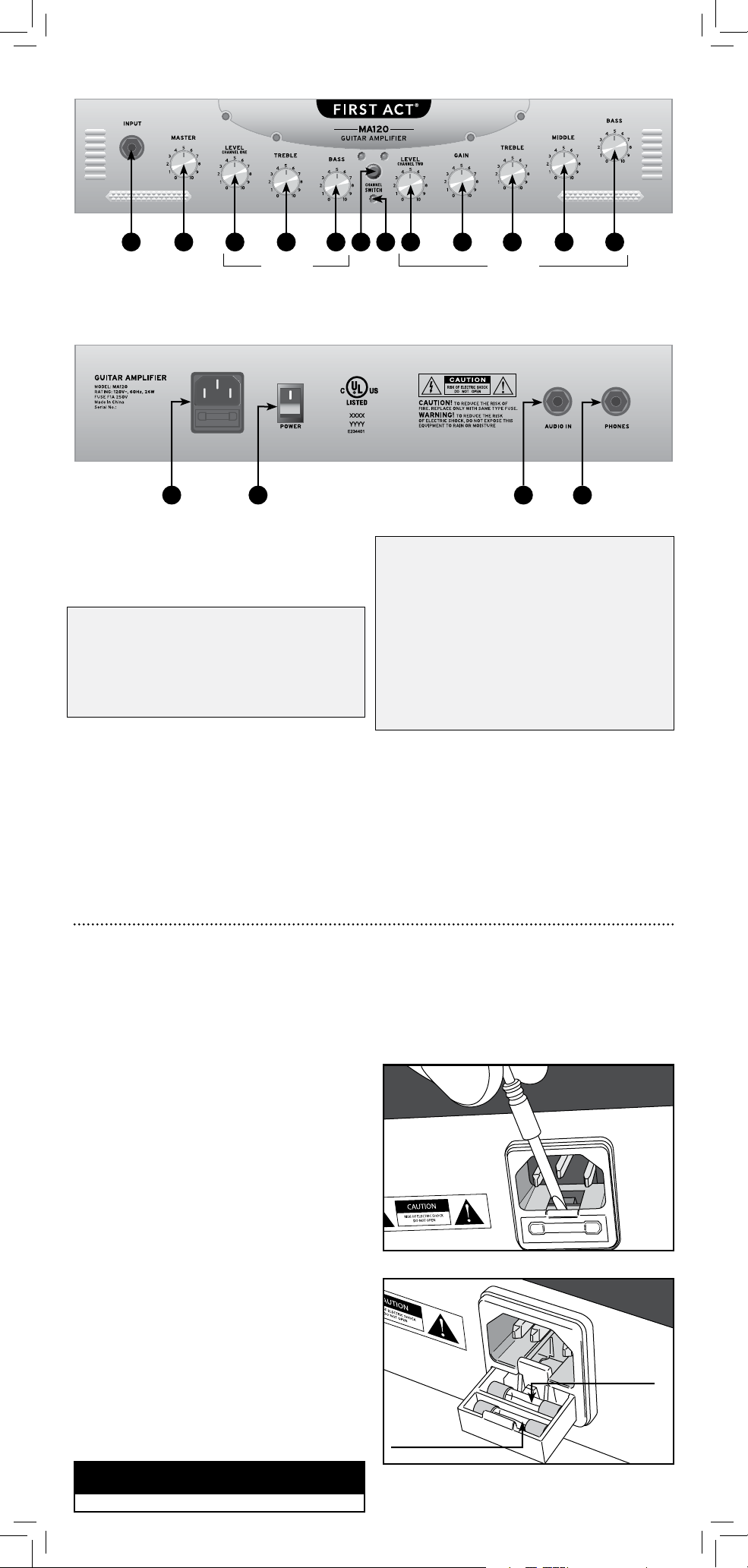
1. INPUT JACK
Connect instrument cable here (1/4” jack).
2. MASTER
Controls the total output level of amplifier.
CHANNEL 1 – CLEAN C HANNEL
3. LEVEL
Controls the output level.
4. TREBLE
Adjusts high frequency output.
5. BASS
Adjusts low frequency output.
6. CHANNEL SWITCH
Switch off/out for Channel 1–indicated
by green LED.
Switch on/in for Channel 2–indicated
by red LED.
7. LED
Indicates amplifier power on/off.
CHANNEL 2 – DISTORTION CHANNEL
8. LEVEL
Controls the output level.
9. GAIN
Controls the input level. Increasing gain
adds distortion, or overdriven rock tone;
decreasing gain produces a cleaner sound.
10. TREBLE
Adjusts high frequency output.
11. MIDDLE
Adjusts middle frequency output.
12. BASS
Adjusts low frequency output.
13. POWER ADAPTOR/ FUSE COMPARTMENT
Connection for power cable. Use only the
power cable supplied with this amplifier.
14. POWER
On/off switch.
15. AUDIO IN
Input jack for external audio device such as
CD or MP3 player (device should have its
own volume control).
16. PHONES
Connects to stereo headphones, which
cancels speaker output.
1 4 632
1413
FAC E P L ATE
BACK P L ATE
RE P LA C IN G TH E F U SE
An additional fuse has been enclosed in the fuse
compartment of your amplifier, directly below
the power input. The fuse compartment contains
an active fuse and a replacement. The fuse protects
against power surges. If your amplifier does not
power up as usual, the fuse may need to
be replaced.
If the fuse fails:
1. Turn the amplifier power off.
2. Unplug the amplifier.
3. Detach the power cord and set aside.
4. Carefully insert a flathead screwdriver to
open the fuse compartment. Be careful not
to break the fuse inside.
5. Remove the blown fuse from the inner
(active) slot.
6. Move the new fuse from the outer slot to the
inner slot.
7. Close the fuse compartment.
8. Discard the blown fuse.
Note: If you replace the fuse and the amplifier
still does not power up, have the unit checked by
a qualified repair technician.
Open the fuse compartment.
Remove the blown fuse from the inner (active)
slot. Move the new fuse from the outer slot to
the inner slot.
US I N G ANO TH ER TYP E IS A P OT E NT IAL FI R E H AZA R D.
CAUTION
REPLACE ONLY WITH SAME
TYP E 250V, 1A FUSE .
ACTIVE FUSE
REPLACEMENT FUSE
SPECIFICATIONS
Output Power:
20 watts RMS
Frequency Range:
40 Hz ~ 8 kHz
Speaker:
8" / 25W / 4 ohms
Input Sensitivity:
26 mV
Power Supply:
Detachable,
UL-approved
power cable
Dimensions:
(LxWxH)
12.5" x 13" x 6.75"
Weight:
15 lbs.
SPECIFI CATI ONS SUBJECT TO CHANGE W ITHOUT NOTIC E
5 8 9 10 11 127
15 16
CHA NNEL 1
CHA NNEL 2
 Loading...