


i4618
Manual P/N 820-1552 Rev. A 1261-7201-00
SIGNALING
LISTED
U
L
ATTENTION: Please take a few minutes to thoroughly read this
user’s guide which should be saved for future reference and
passed on to any subsequent owner.
Smoke Alarm
User’s Guide
• 120 Volt Smoke Alarm with 9 Volt Battery Back-up
• Front Load Battery
• Test and Hush
®
Button
i4618, i4718, i5000 Series
Model: i4618

Smoke Alarm Procedure
NEVER IGNORE THE SOUND OF THE ALARM!
Smoke alarms are designed to minimize false alarms. Cigarette
smoke will not normally set off the alarm, unless the smoke is
blown directly into the alarm. Combustion particles from cook-
ing may set off the alarm if it is located too close to the cook-
ing area. Large quantities of combustion particles are generat-
ed from spills or when broiling. Using the fan on a range hood
which vents to the outside (non-recirculating type) will also
help remove these combustion particles from the kitchen.
If the alarm sounds, check for fires first. If a fire is discovered,
follow these steps. Become thoroughly familiar with these
steps and review with all family members:
• Alert small children in the home.
• Leave immediately by your escape plan. Every second
counts, so don’t waste time getting dressed or picking up
valuables.
• In leaving, don’t open any inside door without first feeling its
surface. If hot, or if you see smoke seeping through cracks,
don’t open that door! Instead, use your alternate exit. If the
inside of the door is cool, place your shoulder against it,
open it slightly and be ready to slam it shut if heat and
smoke rush in.
• If the air is smoky, stay close to the floor. Breathe shallowly
through a cloth, wet if possible.
• Once outside, go to your selected meeting place and make
sure everyone is there.
• Call the fire department from your neighbor’s home - not
from yours!
• Don’t return to your home until the fire officials say that it is
all right to do so.
What to do When the Alarm Sounds!

A.C. Wire-in Single and/or Multiple Station (up to 24 Devices) Ionization
Smoke Alarm with 9 Volt Battery Back Up and SMART HUSH
TM
Control to
temporarily silence nuisance alarms.
Thank you for purchasing this smoke alarm. It is an important part of your family’s
home safety plan. You can trust this product to provide the highest quality safety
protection. We know you expect nothing less when the lives of your family are at
stake. Firex alarms and accessories CAN ONLY BE interconnected with other Kidde
and FireX alarms and accessories as well as specified brands and models of inter-
connect compatible alarms. Connection of Firex products to a non-specified manu-
facturer’s interconnect system, or connection with non-specified equipment from
another manufacturer into an existing Firex system could result in nuisance alarm-
ing, failure to alarm, or damage to one or all of the devices in the interconnect sys-
tem. Refer to the User’s Guide supplied with each Firex product for interconnect
compatible models, brands, and devices. Refer to the wiring instructions in section
3 for NFPA initiating device limits.
This alarm detects products of combustion using the ionization technique. It
contains 0.9 microcurie of Americium 241, a radioactive material (see Section 9).
Distributed under U.S. NRC License No. 32-23858-01E. Manufactured in compli-
ance with U.S. NRC safety criteria in 10 CFR 32.27. The purchaser is exempt
from any regulatory requirements. Do not try to repair the smoke alarm yourself.
Refer to the instructions in Section 12 for service.
IMPORTANT! READ ALL INSTRUCTIONS BEFORE INSTALLATION AND KEEP
THIS MANUAL NEAR THE ALARM FOR FUTURE REFERENCE.
CONTENTS OF THIS MANUAL
1 -- RECOMMENDED LOCATIONS FOR SMOKE ALARMS
2 -- LOCATIONS TO AVOID
3 -- INSTALLATION INSTRUCTIONS
4 -- OPERATION AND TESTING
5 -- NUISANCE ALARMS
6 -- MAINTENANCE
7 -- LIMITATIONS OF SMOKE ALARMS
8 -- GOOD SAFETY HABITS
9 -- NRC INFORMATION
10 -- NFPA PROTECTION STANDARD 72
11 -- CALIFORNIA STATE FIRE MARSHAL REQUIRED INFORMATION
12 -- SERVICE AND WARRANTY

WARNING! REMOVAL OF THE SMOKE ALARM BATTERY AND DISCONNECT-
ING or LOSS OF A.C. POWER WILL RENDER THE SMOKE ALARM INOPERATIVE.
ELECTRICAL RATING: 120 VAC, 60HZ, 80mA maximum per alarm (maximum
80mA for originating unit with 24 devices interconnected).
1. RECOMMENDED LOCATIONS FOR ALARMS
• Locate the first alarm in the immediate area of the bedrooms. Try to monitor
the exit path as the bedrooms are usually farthest from the exit. If more than
one sleeping area exists, locate additional alarms in each sleeping area.
• Locate additional alarms to monitor any stairway as stairways act like chim-
neys for smoke and heat.
• Locate at least one alarm on every floor level.
• Locate an alarm in every bedroom.
• Locate an alarm in every room where electrical appliances are operated (i.e.
portable heaters or humidifiers).
• Locate an alarm in every room where someone sleeps with the door closed.
The closed door may prevent an alarm not located in that room from waking
the sleeper.
• Smoke, heat, and combustion products rise to the ceiling and spread horizon-
tally. Mounting the smoke alarm on the ceiling in the center of the room
places it closest to all points in the room. Ceiling mounting is preferred in
ordinary residential construction.
• For mobile home installation, select locations carefully to avoid thermal barri-
ers that may form at the ceiling. For more details, see MOBILE HOME INSTAL-
LATION below.
• When mounting an alarm on the ceiling, locate it at a minimum of 4” (10 cm)
from the side wall (see FIGURE 1).
• When mounting the alarm on the wall, use an inside wall with the top edge
of the alarm at a minimum of 4” (10 cm) and a maximum of 12” (30.5 cm)
below the ceiling (see FIGURE 1).
• Put smoke alarms at both ends of a bedroom hallway or large room if the
hallway or room is more than 30 feet (9.1 m) long.
• Install Smoke Alarms on sloped, peaked or cathedral ceilings at or within 3ft
(0.9m) of the highest point (measured horizontally). NFPA 72 states: “Smoke
alarms in rooms with ceiling slopes greater than 1 foot in 8 feet (.3m in 2.4
m) horizontally shall be located on the high side of the room.” NFPA 72
states: “A row of detectors shall be spaced and located within 3 ft (0.9m) of
the peak of the ceiling measured horizontally” (see FIGURE 3).
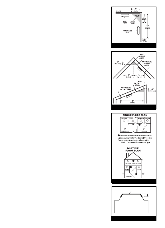
• Install Smoke Alarms on tray-shaped ceilings (coffered
ceilings) on the highest portion of the ceiling or on the
sloped portion of the ceiling within 12” (305mm) verti-
cally down from the highest point (see figure 4).
MOBILE HOME INSTALLATION
Modern mobile homes have been designed and built
to be energy efficient. Install smoke alarms as recom-
mended above (refer to RECOMMENDED LOCATIONS
and FIGURES 1 and 2).
In older mobile homes that are not well insulated com-
pared to present standards, extreme heat or cold can
be transferred from the outside to the inside through
poorly insulated walls and roof. This may create a
thermal barrier which can prevent the smoke from
reaching an alarm mounted on the ceiling. In such
units, install the smoke alarm on an inside wall with
the top edge of the alarm at a minimum of 4” (10 cm)
and a maximum of 12” (30.5 cm) below the ceiling
(see FIGURE 1).
If you are not sure about the insulation in your mobile
home, or if you notice that the outer walls and ceiling
are either hot or cold, install the alarm on an inside
wall. For minimum protection, install at least one
alarm close to the bedrooms. For additional protec-
tion, see SINGLE FLOOR PLAN in FIGURE 2.
WARNING: TEST YOUR SMOKE ALARM OPERA-
TION AFTER R.V. OR MOBILE HOME VEHICLE HAS
BEEN IN STORAGE, BEFORE EACH TRIP AND AT
LEAST ONCE A WEEK DURING USE.
2. LOCATIONS TO AVOID
• In the garage. Products of combustion are present
when you start your automobile.
• Less than 4” (10cm) from the peak of an “A” frame
type ceiling.
• In an area where the temperature may fall below
40ºF or rise above 100ºF, such as garages and unfin-
ished attics.
ANYWHERE ALONG
THIS BOLD SURFACE
12”
(300mm)
FIGURE 4
FIGURE 1
FIGURE 3
FIGURE 2

• In dusty areas. Dust particles may cause nuisance alarm or failure to alarm.
• In very humid areas. Moisture or steam can cause nuisance alarms.
• In insect-infested areas.
• Smoke alarms should not be installed within 3 ft (.9m) of the following: the
door to a kitchen, the door to a bathroom containing a tub or shower, forced
air supply ducts used for heating or cooling, ceiling or whole house ventilating
fans, or other high air flow areas.
• Kitchens. Normal cooking may cause nuisance alarms. If a kitchen alarm is
desired, it should have an alarm silence feature or be a photoelectric type.
• Near fluorescent lights. Electronic “noise” may cause nuisance alarms.
• Smoke alarms are not to be used with detector guards unless the combination
(alarm and guard) has been evaluated and found suitable for that purpose.
3. INSTALLATION INSTRUCTIONS
WIRING REQUIREMENTS
• This smoke alarm should be installed on a U.L. listed or recognized junction
box. All connections should be made by a qualified electrician and all wiring
used shall be in accordance with articles 210 and 300.3(B) of the U.S. National
Electrical Code ANSI/NFPA 70, NFPA 72 and/or any other codes having jurisdic-
tion in your area. The multiple station interconnect wiring to the alarms must
be run in the same raceway or cable as the AC power wiring. In addition, the
resistance of the interconnect wiring shall be a maximum of 10 ohms.
• The appropriate power source is 120 Volt A.C. Single Phase supplied from a
non-switchable circuit which is not protected by a ground fault interrupter.
• WARNING: This alarm cannot be operated from power derived from a square
wave, modified square wave or modified sine wave inverters. These types of
inverters are sometimes used to supply power to the structure in off grid
installations, such as solar or wind derived power sources. These power
sources produce high peak voltages that will damage the alarm.
WIRING INSTRUCTIONS FOR A.C. QUICK CONNECT HARNESS
CAUTION! TURN OFF THE MAIN POWER TO THE CIRCUIT BEFORE WIRING
THE ALARM.
• For alarms that are used as single station, DO NOT CONNECT THE RED WIRE
TO ANYTHING. Leave the red wire insulating cap in place to make certain that
the red wire cannot contact any metal parts or the electrical box.
• When alarms are interconnected, all interconnected units must be powered
from a single circuit.
 Loading...