

Firetide HotPort 8020 User Manual
Firetide Installation Guide
HotPort 8020Mesh Node
Published Dec 2017
Revised Feb 2018

© 2017 Firetide, Inc. All rights reserved
Firetide, the Firetide logo, HotPort are all trademarks of Firetide Inc. All other trademarks are
the property of their
change without notice.
respective owners.
.
Information in this document is subject to
Fire
tide, Inc
2105 S. Bascom Avenue, Suite 220
Campbell, CA 95008
USA
.
www.firetide.com
HotPort 8020 Mesh Node Installation Guide
1

Contents
1 About this document............................................................................................................................ 4
1.1 Audience
1.2 Instructions to purchaser and installer
1.3 Purpose
1.4 Conventions
1.5 Document feedback
1.6 Contacting customer support
2 HotPort 8020 mesh node ..................................................................................................................... 5
3 Installation ............................................................................................................................................ 5
Preparing what you need to install ........................................................................................................... 5
3.1 HotPort mesh node in an IP67 enclosure
3.1.1 Package contents of 8020 mesh node
The following accessories can be purchased separately from Firetide
3.2 Interface of an outdoor mesh
3.2.1 Node LEDs
3.2.2 Console Port/Reset
............................................................................................................................................. 4
...................................................................................................... 4
............................................................................................................................................... 4
......................................................................................................................................... 4
............................................................................................................................... 4
.................................................................................................................. 4
.................................................................................................. 6
............................................................................................... 6
................................................................. 6
.................................................................................................................. 7
.................................................................................................................................... 8
........................................................................................................................ 9
3.2.3 Ethernet ports
3.2.4 Antenna Connectors
3.2.5 Pressure relief valve
3.2.6 Ground screw point
4 Test before you install ........................................................................................................................ 10
4.1 Before you install:
4.2 Tests to do
4.3 Licenses which are not included
4.4 Certification requirement
5 Doing the tests
6 Power Specifications
6.1 Power input and Power out
6.2 Operating TX Power limit of radio
7 Environmental Specifications
8 HotPort8020 mesh node installation
......................................................................................................................................... 10
....................................................................................................................................... 10
............................................................................................................................... 9
.................................................................................................................... 10
..................................................................................................................... 10
..................................................................................................................... 10
............................................................................................................................... 10
............................................................................................................ 10
..................................................................................................................... 10
............................................................................................................................... 12
.................................................................................................................. 12
.......................................................................................................... 12
............................................................................................................... 12
.................................................................................................... 12
HotPort 8020 Mesh Node Installation Guide
2

8.1 Installation Steps:
8.2 Tools required
8.3 Doing the site survey
8.4 Safe installation practices
8.5 Preparing a mesh node for installation
8.6 Preparing earth ground
8.7 Installing a mesh node and antenna assembly
8.8 Attaching the mesh node to a wall
8.9 Attaching a mesh node to a vertical pole
8.10 Attaching a mesh node to a horizontal pole
8.11 Panel antenna Assembly
8.12 Mesh node installation with RF cable assembly on a vertical pole.
9 Trouble shooting ................................................................................................................................ 24
Cannot see a mesh node in Web NMS.................................................................................................... 24
After multiple reboots a mesh node is missing ........................................................................................ 24
................................................................................................................................ 12
.................................................................................................................................... 12
........................................................................................................................... 13
..................................................................................................................... 13
................................................................................................... 14
........................................................................................................................ 15
......................................................................................... 16
......................................................................................................... 17
................................................................................................ 18
............................................................................................. 19
...................................................................................................................... 21
.............................................................. 22
Performance not as expected ................................................................................................................. 24
Resetting an outdoor mesh node to factory default settings ................................................................. 25
10 Weather proof procedures ............................................................................................................ 26
10.1
Tools and materials ........................................................................................................................ 26
To make a weatherproof connection you need the following tools and materials: .............................. 26
Making weatherproof cable to node connections.................................................................................. 26
Y
ou need to make weather proof two connections:
To make a weather proof cable to node connection: ............................................................................ 26
11 Information to User, Purchaser & Installer ................................................................................... 28
11.1
Federal Communication Commission Interference Statement .................................................... 28
.................................................................................... 26
HotPort 8020 Mesh Node Installation Guide
3

1 About this document
This section lists the audience, purpose, summary of information, and conventions used in this document.
1.1 Audience
This documents intended for certified professionals who install Firetide wireless solutions.
1.2 Instructions to purchaser and installer
This equipment must be professionally installed. The installer is responsible for adjusting the transmit power output of the
system to assure compliance with FCC Part15 EIRP limits and human radiation safety regulations.
1.3 Purpose
This document has the information and procedures necessary to install and do basic tests with Firetide HotPort 8020 mesh
node.
1.4 Conventions
Certaininformationhasspecialmeaningforthereader.Thisinformationappearswith an icon that indicates a particular condition,
such as a warning or caution, or a label, such as “Note” or “Best Practice”.
Electrical hazards are those environments where the danger of electrocution is probable. This image appears
before each electrical hazard statement.
Warnings contain safety information that you must obey. If you do not obey the instruction in warning, the result
might include serious injury or death. This image appears before each warning statement.
Cautions contain information that you should obey to avoid minor injury, inconvenience, and damage to equipment.
This image appears before each caution statement.
Notes contain optional advice and information particular to a special case or application.
Best practices contain specific recommendations based on industry-standard expectations.
1.5 Document feedback
If you find an error or content missing from this document, we want to hear about it. You can send you feedback about any
of our documents to FT-Techpubs@firetide.com.
1.6 Contacting customer support
If you need support, depending on the problem, you might be asked for this information:
Description of the problem
FMA and an installed management license
Channel and frequency plan
Recent spectrum analysis
Device topology in Google Earth (KMZ file)
Network map or topology plan with device information
You must also have administrator access to the mesh to be able to receive technical support.
The next table lists the contact information for customer support.
Worldwide customer support
Americas
Days/Hours Contact
Monday to Friday 7:00 am to
5:30 pm PST (Pacific Standard
T ime)
http://www.firetide.com/support
+1 (877) FIRETIDE, extension 2
+1 (408) 399-7771, extension 2
+1 (408) 355-7271
HotPort 8020 Mesh Node Installation Guide
4

License
Descriptions
Remarks
Africa
Asia
Australia
Europe
Monday to Friday
8:00 am to 5:30 pm IST (India
Standard Time)
http://www.firetide.com/support
+91-8040215111
Fax +1(408) 317-2257
2 HotPort 8020 mesh node
Firetide HotPortTMmesh node has two radios which operate in 802.11a, n and ac 4x4 MIMO mode.
The default configuration is 2x2 MIMO. With Software license 4x4 MIMO can be enabled.
The following software licenses are available. **
SW-8020-2x2MIMO
SW-8020-4x4MIMO
SW-FMA-Mgmt.
SW-Mobility
802.11n/ac 2x2MIMO
802
.11n/ac
Management License
Mobility License
4x4 MIMO
Default
Add on license
Add on license
Add on license
If you plan on using DFS, it is mandatory to take training class from Firetide. On successful completion of the class Firetide
will provide login credentials for DFS configuration using Firetide Management Appliance.
**Subject to software implementation.
3 Installation
Please read before Installation
You must complete the training program and be certified by Firetide to be able to install Firetide
products.
Before you install an outdoor mesh node in a permanent location, you need to make sure you have all of the
correct components and make sure the components are operational.
Preparing what you need to install
To get what you need to set up a mesh node:
Open the box.
Remove the contents.
Check the contents for damage. If a part is missing or damaged, call your Firetide reseller.
If the contents are good and correct, keep the box for future use.
HotPort 8020 Mesh Node Installation Guide
5
3.1 HotPort mesh node in an IP67 enclosure
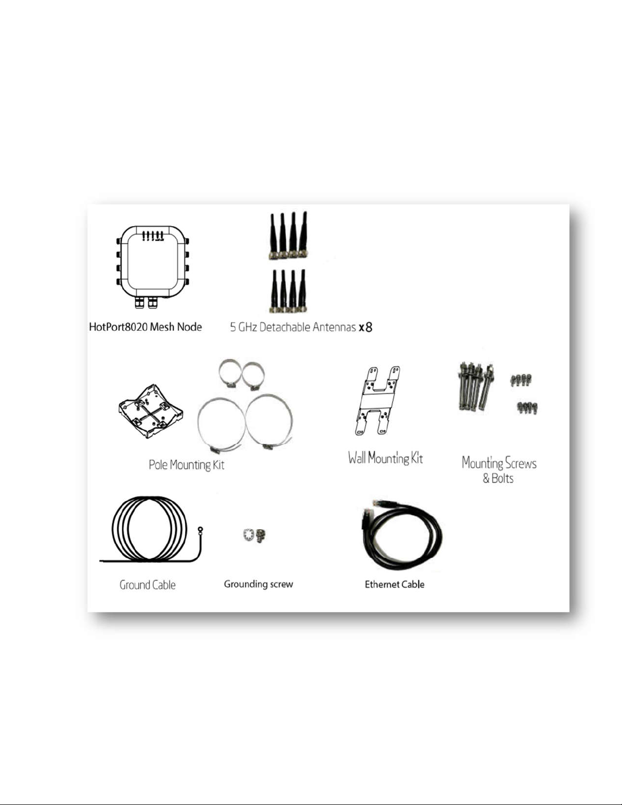
3.1.1 Package contents of 8020 mesh node
Eight detachable 5GHz Omni- directional antennas for staging
Pole and wall mounting kit
Mounting screws and bolts
Ground cable
Cat6 Ethernet cable
The following accessories can be purchased separately from Firetide
4x4 MIMO 18.5 dBi gain 5G panel outdoor rated antenna
7 dBi gain 5G dipole antenna
RF cable assembly with lightning arrester
802.3 AT+ PoE injector
HotPort 8020 Mesh Node Installation Guide
6
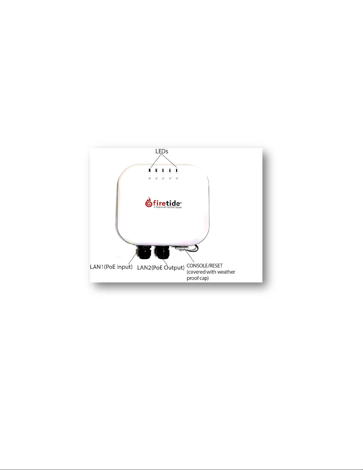
3.2 Interface of an outdoor mesh
The following picture of 8020 mesh node shows the
node LEDs, antenna port connectors of the radio, Ethernet ports(PoE input and PSE output port),
debug console/reset and the pressure valve with weatherproof cap protection and node ground
point.
For information about cables and accessories approved for use with Firetide devices,
refer to the Accessories Guide.
Front View
front view and the rear view
describing
HotPort 8020 Mesh Node Installation Guide
7
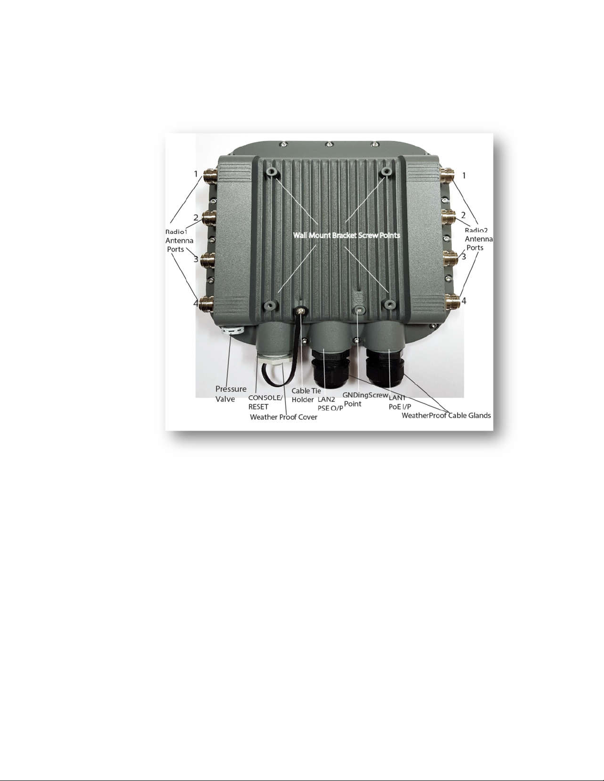
Rear View
3.2.1 Node LEDs
Hotport8020 mesh node has 5 LEDs as shown in the following picture.
o Power LED
OFF: Mesh node does not receive power.
Amber: Device is powering up
Green: Device is powered up and ready to use
o Ethernet LEDs of LAN1 and LAN2 port
OFF: No Ethernet link detected
Amber: Link speed (10/100 Mbps),Blinking - Activity
Green-Link speed (1000Mbps), Blinking- Activity
o Radio1 and Radio2 LEDs
OFF: No Radio neighbor detected
Green: Radio Neighbor connected, Blinking-Activity
HotPort 8020 Mesh Node Installation Guide
8
 Loading...