

Page 1
Installation & Setup Guide
HotPoint
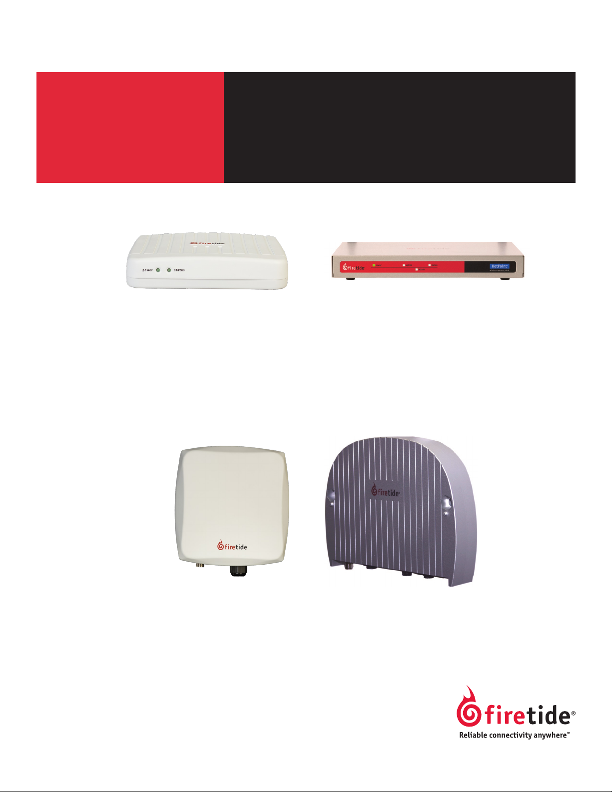
HotPoint 4100 Indoor Access Point HotPoint 4500 Indoor Access Point
HotPoint 4000 Family
Wireless Access Points
HotPoint 4200 Outdoor Access Point
Manual Revision 1.0 020809
The contents of this Installation Guide are subject to change without notice.
Please refer to the Firetide partners web site, partners.retide.com, for current versions.
HotPoint 4600 Outdoor Access Point
Page 2

Safety Instructions
Outdoor HotPoint APs must be installed by a qualied professional. Failure to install this equipment properly may result in equipment damage, personal injury, or death.
Explanation of Graphic Symbols
This symbol alerts the user to the presence of non-insulated dangerous voltage that
may be of sufcient magnitude to constitute a risk of lethal electric shock to persons.
This symbol alerts the user to important operating, maintenance, and servicing instruc-
tions. Failing to comply with instructions may result in electrical shock.
This symbol alerts the user to the presence of important operating, maintenance, and
servicing instructions. Failing to comply with this instruction may result in a hazard.
Do not open the cover
Dangerous voltages inside.•
No serviceable parts inside.•
Refer to qualied service personnel.•
Unit has tamper-evident labeling that indicates when the cover has been removed.•
Caution! Risk of electric shock!
POWER LINES CAN BE LETHAL
Do not install Firetide products where possible contact with power lines can be made. Antennas,
poles, towers, guy wires, or cables may lean or fall and contact these lines. People may be injured
or killed if they are touching or holding any part of equipment when it contacts electric lines. Make
sure there is NO possibility that equipment or personnel can come in contact directly or indirectly
with power lines.
ASSUME ALL OVERHEAD LINES ARE POWER LINES
The horizontal distance from a tower, pole or antenna to the nearest power line should be at least
twice the total length of the pole/antenna combination. This will ensure that the pole will not
contact power if it falls either during or after installation.
SURVEY THE SITE
Look over the entire site before beginning any installation and anticipate possible hazards. Never
assume anything without checking it out for yourself! Don’t take shortcuts!
TO AVOID FALLING, USE SAFE PROCEDURES WHEN WORKING AT HEIGHTS ABOVE GROUND
Select equipment locations that will allow safe and simple installation.•
Don’t work alone. A friend or co-worker can save your life if an accident happens.•
Don’t attempt repair work when you are tired. Not only will you be more careless, but your primary diagnostic tool - deduc-•
tive reasoning - will not be operating at full capacity.
Use approved non-conducting ladders, shoes, and other safety equipment. Make sure all equipment is in good repair.•
If a tower or pole begins falling, don’t attempt to catch it. Stand back and let it fall. •
If anything such as a wire or pole does come in contact with a power line, DON’T TOUCH IT OR ATTEMPT TO MOVE IT. In-•
stead, save your life by calling the power company.
Don’t attempt to erect antennas or towers on windy days.•
MAKE SURE ALL TOWERS AND POLES ARE SECURELY GROUNDED, AND ELECTRICAL CABLES CONNECTED TO ANTENNAS HAVE •
LIGHTNING ARRESTORS. This will help prevent re damage or human injury in case of lightning, static build-up, or short
circuit within equipment connected to the antenna. The HotPort outdoor node has built-in lightning protection. Be sure
that any other equipment connected to the HotPort node also has the same level of protection.
The base of the antenna pole or tower must be connected directly to the building protective ground or to one or more •
approved grounding rods, using 10 AWG ground wire and corrosion-resistant connectors.
Refer to the National Electrical Code for grounding details.•
IF AN ACCIDENT SHOULD OCCUR WITH THE POWER LINES
DON’T TOUCH THAT PERSON, OR YOU MAY BE ELECTROCUTED.•
Use a non-conductive dry board, stick, or rope to push or drag them so they no longer are in contact with electrical •
power.
Once they are no longer contacting electrical power, administer CPR if you are certied.•
Immediately have someone call for medical help.•
2 AP User Guide February 2009
Page 3

Table of Contents
Chapter 1 Introduction to the HotPoint Family ....................................................................4
HotPoint AP Common Features . . . . . . . . . . . . . . . . . . . . . . . . . . . . . . . . . . . . . . . . . . . . . . . . . . . . . . . . . . . . . . . . . . . . . . .5
Chapter 2 Setting Up Your Equipment - Model 4100 Indoor Installation ...................................................6
Chapter 3 Setting Up Your Equipment - Model 4200 Outdoor Installation ..................................................7
Chapter 4 Setting Up Your Equipment - Model 4500 Indoor Installation ...................................................9
Chapter 5 Setting Up Your Equipment - Model 4600 Outdoor Installation .................................................10
Chapter 6 Planning Your Software Deployment ...................................................................11
Understanding APs, AP Groups, VAPs, & VAP Groups . . . . . . . . . . . . . . . . . . . . . . . . . . . . . . . . . . . . . . . . . . . . . . . . . . . . . . . . 11
Basic Setup Sequence . . . . . . . . . . . . . . . . . . . . . . . . . . . . . . . . . . . . . . . . . . . . . . . . . . . . . . . . . . . . . . . . . . . . . . . . . . . . 13
Chapter 7 Software Conguration ............................................................................14
Basic VAP Settings . . . . . . . . . . . . . . . . . . . . . . . . . . . . . . . . . . . . . . . . . . . . . . . . . . . . . . . . . . . . . . . . . . . . . . . . . . . . . .15
Appendix A Specications ..................................................................................19
Appendix B Regulatory Notices . . . . . . . . . . . . . . . . . . . . . . . . . . . . . . . . . . . . . . . . . . . . . . . . . . . . . . . . . . . . . . . . . . . . . . . . . . . . . .22
Appendix C Ethernet Wiring ................................................................................23
Appendix D Reset Procedure ................................................................................23
Firetide Limited End User Product Warranty
Pursuant to all provisions described herein, Firetide hardware products and Firetide
antennas are warranted for one (1) year from the date of purchase against defects
in the build materials and workmanship. Firetide does not warrant that the Products
will meet any requirements or specications of any End User Customer. This warranty
applies to the entire Firetide product, including the AC power adapter.
Pursuant to all provisions described herein, Firetide software products are warranted
for ninety (90) days from the date of purchase against defects in the build materials
and workmanship. Firetide also warrants that the Software will materially conform
to the documentation supplied by Firetide with the Software. In the event that the
Software fails to materially conform to the documentation and an authorized Firetide
reseller is notied in writing of such failure within the warranty period, Firetide or
its reseller shall use commercially reasonable efforts to promptly correct the nonconformity. Firetide does not warrant that the use of the Software will be uninterrupted
or error free.
The above warranties are void if the alleged defect cannot be veried by Firetide or if,
as determined by Firetide, the product failure was due to tampering, abuse, misuse,
accident, shipping, handling, or storage; or if the product has been installed, used, or
maintained in a manner not described in the product user manual; or if the product
has been altered in any way; or if product serialization has been altered. Any attempt
to disassemble or repair the product by anyone other than Firetide immediately voids
this warranty.
This warranty applies only to the original End User purchaser of the product and may
not be transferred to any other individual or entity.
THE FOREGOING ARE THE EXCLUSIVE WARRANTIES APPLICABLE TO THE PRODUCT INCLUDING THE SOFTWARE, AND THE EXCLUSIVE REMEDY FOR DEFECTS IN THE PRODUCT.
FIRETIDE DISCLAIMS ALL OTHER WARRANTIES, WHETHER EXPRESS, IMPLIED, STATUTORY OR OTHERWISE, INCLUDING BUT NOT LIMITED TO IMPLIED WARRANTIES OF MERCHANTABILITY, NON-INFRINGEMENT OR FITNESS FOR A PARTICULAR PURPOSE. SOME
LAWS DO NOT ALLOW THE EXCLUSION OF IMPLIED WARRANTIES SO TO THAT EXTENT
THIS LIMITATION MAY NOT APPLY TO YOU.
In no event will Firetide be liable for any special, incidental, consequential, punitive
or indirect damages whatsoever (including, without limitation, damages for loss of
prots, business interruption, loss of information, or other pecuniary loss) arising out
of the use or inability to use the product or the performance, interruption or failure of
the product, irrespective of the cause of action, even if Firetide has been advised of
the possibility of such damages. Firetide’s cumulative liability for all claims arising out
of or in connection with this warranty will not exceed the amount paid by the original
End User purchaser to purchase the product. The amounts payable for the product are
based in part on these limitations and these limitations shall apply notwithstanding
the failure of essential purpose of any remedy. Some jurisdictions do not allow the
exclusion or limitation of incidental or consequential damages, so to that extent the
above limitations or exclusions may not apply to you.
By using the product the original End User purchaser agrees to and is bound by these
terms and conditions.
In the event that a product fails to meet this warranty and Firetide’s authorized reseller is notied in writing of such failure within the warranty period, Firetide shall,
at its own discretion, either repair the product or replace it with the same or a
functionally-equivalent product free of charge. Replacement products may contain
refurbished materials in whole or in part. Firetide will honor this warranty provided
the product is returned through an authorized Firetide reseller or dealer with shipping charges prepaid, along with a proof of purchase describing the original purchase
date and product serial numbers if applicable. The authorized reseller must acquire
a Return Materials Authorization (RMA) number from Firetide prior to returning any
product. Firetide does not accept shipments of defective products without shipping
charges prepaid.
Please contact your Firetide dealer for instructions on returning defective or damaged
products for repair or replacement. Do not return products to Firetide, Inc. Please keep
all original packaging materials in the event they are needed to return the product
for servicing.
Firetide - Reliable Connectivity Anywhere 3 February 2009
Page 4

Chapter 1 Introduction to the HotPoint Family
The Firetide™ HotPoint™ family of wireless access points are the newest addition to the company’s
line of high performance wireless mesh networking products. HotPoints provide an enterprise-class
wireless access solution and can be used as full-function standalone access points, or as part of
an integrated, triple-play wireless mesh network. Available in indoor and outdoor models, they
include a high power, extended-range radio, multiple antenna options, robust security features,
and multiple SSID support.
The Firetide HotPoint wireless access points can serve as companion units to the Firetide HotPort
Wireless Mesh Network. Each AP allows 802.11 wireless clients to connect to the network. Such
clients include laptops, wireless security cameras, VoIP phones, and portable terminal and POS
devices.
Firetide’s modular design offers several benets. Among them are:
A HotPoint access point can be connected to a Firetide mesh node to provide Wi-Fi access to any •
location, without the need for backhaul cabling.
A HotPoint access point can connect directly to a conventional wired infrastructure. This elimi-•
nates the need to install a Firetide mesh node in locations where wired connectivity is readily
available, while preserving the unied management capabilities for all access points.
Because the access points and mesh nodes are kept in separate enclosures, they can be indepen-•
dently positioned for optimum RF connectivity.
A HotPoint access point can share a Firetide mesh node with other devices for true triple-play •
networking at any mesh node location. This can include a second HotPoint access point operating on a different channel, a video camera, a VoIP device, or even a third party access point.
Firetide HotPort Mesh Network
AutoMesh has been optimized for efciency in wireless mesh environments. The patent-pending
Network Management with
HotView Pro Software
HotView Pro extends management across multiple meshes and enables advanced HotPort function-
HotPoint APs can also be managed via a standard web browser.
Firetide’s wireless mesh technology provides an ideal backhaul capability for 802.11 client traf-
c. Together, the systems provide a complete wireless infrastructure. The HotPort system allows
standard Ethernet devices to operate on the wireless backbone, creating secure and reliable wireless networks for voice, video surveillance, and data. HotPorts connect wirelessly to each other to
form a mesh network. Ethernet packets are automatically switched across the mesh, in a manner
analogous to an Ethernet switch, using AutoMesh™, a proprietary protocol developed by Firetide.
AutoMesh routing protocol delivers up to 30 Mbps throughput and very low latency of 1.5 ms per
hop across the wireless mesh backbone. Trafc prioritization is provided by HotPort mesh 802.1p
or port-based quality of service (QoS) while HotPoint APs provide 802.11e and WMM QoS between
clients and the AP. In addition, the HotPoint access point supports Turbo Mode, providing up to
108 Mbps data rates for clients using the industry-leading Atheros chip set.
HotView™ management software provides full control of Firetide HotPort wireless mesh networks,
including HotPoint APs. The software provides access to all mesh and node settings, including
security, VLAN, class of service, radio power controls, and network gateway interconnects. Live
monitoring features include mesh and node statistics.
ality. Thus, an enterprise can manage all of its HotPort mesh nodes and HotPoint APs worldwide
from anywhere.
4 AP User Guide February 2009
Page 5

HotPoint AP Common Features
Firetide’s HotPoint family shares a common architecture, and most features are supported on all
models. The HotPoint 4100/4200 has a more limited functionality than Firetide’s 4500/4600, unless used with the Firetide WLAN Controller. The WLAN Controller offers a wide range of features
needed by enterprise-class users for all types of APs. Please refer to the HotView Pro Reference
Guide for more information on the WLAN Controller. Key features are summarized in Table 1.
Table 1. Firetide HotPoint AP Family Products & Features
Feature 4100
Radio Features
400 mW transmitter √ √ √ √
Manual xmit power control √ √ √ √
Auto channel select √ √ √ √
2.4 GHz band √ √ √ √
4.9 GHz band √ √ - -
5.0 GHz band √ √ - -
802.11d √ √ √ √
802.11b/g √ √ √ √
802.11a √ √ - Turbo mode (for supported clients) √ √ √ √
WMM QoS √ √ √ √
WDS server - - √ WDS client √ - √ -
Security Features
Rogue AP Detection - - * √ √
802.11i; 40/128 WEP, 128/256 AES, TKIP √ √ √ √
WPA/WPA2 encryption √ √ √ √
AES encryption √ √ √ √
802.1X authentication - √ √ √
Login-based authentication - - * √ URL re-direction - - * √ IP walled garden - - * √ -
802.11f IAPP security handoff - - √ -
802.11r fast handoff - √ √ √
Layer 2 / Layer 3 Roaming - √ - √
Intercell blocking √ √ √ √
Intracell blocking √ √ √ √
MAC address access control √ √ √ √
SSID suppression √ √ √ √
VLANs 4 4 16 16
Network Features
DHCP client √ √ √ √
DHCP server 1/VAP 1/VAP 1/VAP 1/VAP
NAT √ √ √ √
Firewall √ √ √ √
VPN Tunneling / Filtering - - √ Virtualized APs 4 4 16 16
AP Management Groups - √ √ √
Virtualized AP Management Groups - √ √ √
Fairness among connected STAs (to client level) - √ √ √
Per-user rate limiting √ √ √ √
Per-VAP rate limiting √ √ √ √
Maximum clients per AP 32 32 64 64
Management Features
HTTPS access for management √ √ √ √
SNMP v2/v3 - √ √ √
Supports pre-congured 2100/2200 HotClients √ √ √ √
Supports auto-congured 2100/2200 HotClients - - √ √
* Available in a later software release.
4200
alone
with
WLAN
ctlr
4500
4600
alone
with
WLAN
ctlr
Firetide - Reliable Connectivity Anywhere 5 February 2009
Page 6
Chapter 2 Setting Up Your Equipment - Model 4100 Indoor Installation
Introduction
Setup - Indoor Model 4100
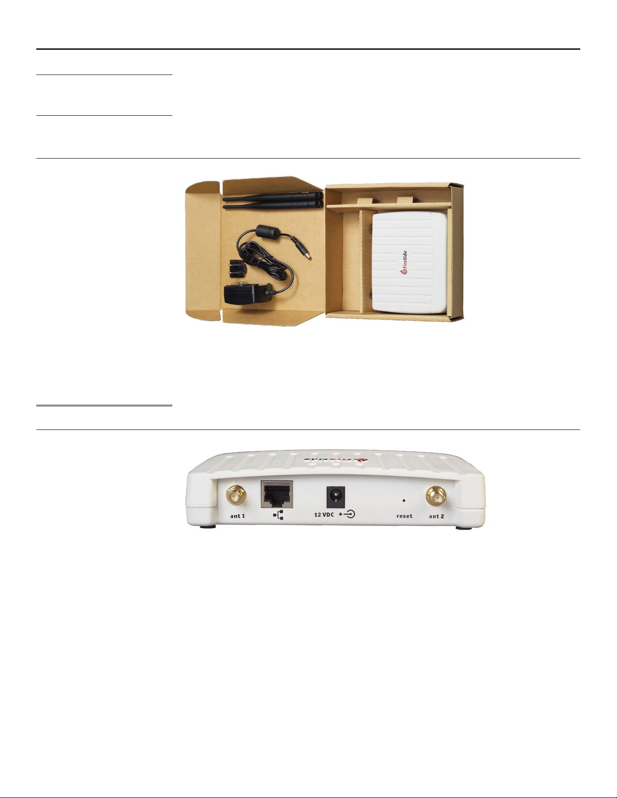
The HotPoint needs power. Note that the AC adapter has interchangeable inserts to t most AC
Figure 1. Model 4100 Indoor Unit - Package Contents
The 4100 needs to connect via a standard Ethernet (RJ-45) cable to the network. Pick a suitable
Antenna Note
Figure 2. Indoor Unit Important Points
The Firetide Model 4100 provides enterprise-class 802.11 wireless access. It can operate as a stand-
alone device, or with Firetide’s Wireless LAN Controller. Congure your HotPoint before installation.
Refer to Chapter 6, or the HotView Pro Reference Guide, for details.
Setup of your new Firetide HotPoint is simple. The package contents are shown in Figure 1.
receptacles in the US, Europe, the UK, Australia, and elsewhere. The adapter will operate on any
voltage from 100 to 240 VAC, from 50 to 60 Hz. If you need PoE capability, use the 4200.
location for the device, and use the supplied power supply to provide power to the unit. The Power
LED should illuminate immediately. Attach the supplied antennas to the two antenna connectors.
Tighten them rmly, by hand, and point them vertically.
Note that the supplied antennas are designed for the 2.4 GHz band, that is, 802.11b and 802.11g
service. The HotPoint 4100 supports operation on the 5 GHz 802.11a band, but you must use a 5
GHz antenna if you wish to use this band.
Antenna 1 ResetPowerEthernet Antenna 2
The Firetide device needs about a minute to boot itself. When it completes this process, the Status
LED will turn green.
6 AP User Guide February 2009
Page 7
Chapter 3 Setting Up Your Equipment - Model 4200 Outdoor Installation
Setup - Outdoor Model 4200
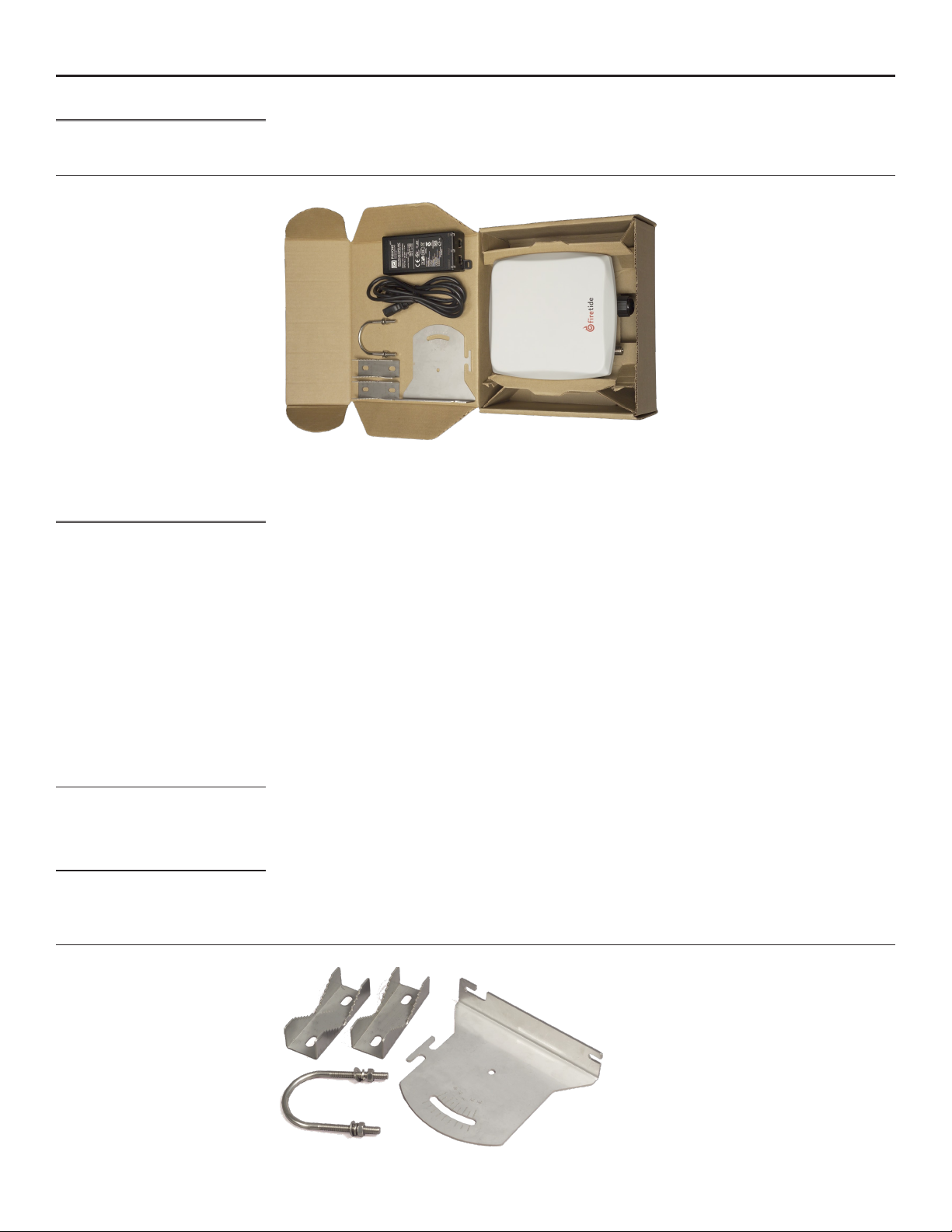
Figure 3. Model 4200 Outdoor Unit - Package Contents
The cable must be a 4-pair cable; smaller cables will not seal in the waterproof connector. The
Assembling the Ethernet Cable
Now you can connect the Ethernet cable to the power feed unit, via the OUT port on the power
Using the Mounting Bracket
Antenna Notes
Figure 4. HotPoint Mounting Bracket
The outdoor HotPoint is packed as shown in Figure 3. Note that an Ethernet cable is NOT included.
You should obtain a weatherproof 4-pair cat-5 cable long enough to reach from the unit to the
indoor location where you will connect with the network. Congure your HotPoint before installation. Refer to Chapter 6, or the HotView Pro Reference Guide, for details.
cable can be pre-terminated; the waterproof connector will pass an RJ-45 plug.
Test the unit before mounting it on the pole or mast. Begin by making the cable.
Remove the weatherproof Ethernet connector cover - the black plug - from the unit.1.
Dismantle it. You will have a housing, a housing insert, a cap, and a gasket.2.
Place the cap over one end of your Ethernet cable.3.
Place the housing insert over the cable.4.
Thread the cable through the housing.5.
Plug the cable into the RJ-45 port visible inside the HotPoint.6.
Thread the housing back into the HotPoint. Make sure the gasket is still in place.7.
Tighten the cap so that it compresses the housing insert to the housing.8.
feed unit. Use a second Ethernet cable to connect the IN port to your PC. Verify operation of the
HotPoint before proceeding.
The bracket is designed to allow easy tilting and aiming of the HotPoint. The bracket allows the
HotPoint to be mounted with its internal antenna oriented for either vertical or horizontal polarization. It is also designed to allow mounting on either a horizontal or vertical pole. Note that the
internal antenna polarization is vertical when the connectors are pointed down.
Note that the antenna is built in to the HotPoint. The HotPoint should face the equipment it is
intended to connect with. The built-in antenna is designed for the 2.4 GHz band, that is, 802.11b
and 802.11g service. The HotPoint 4200 supports operation on the 5 GHz 802.11a band, but you
must use an external 5 GHz antenna if you wish to use this band. Otherwise, keep the plastic cover
on this connected to prevent water from getting into the unit.
Firetide - Reliable Connectivity Anywhere 7 February 2009
Page 8
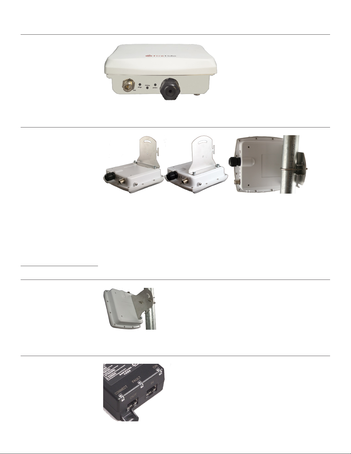
In order to avoid climbing up and down the pole twice, power up the HotPoint before proceeding
with the installation. The only connection you need is the Ethernet; it provides power as well.
Figure 5. HotPoint Outdoor Unit Connections
Attach the bracket to the back of the HotPoint, using the two slotted holes shown on the right side
of the bracket, as shown in Figure 4. Select two holes on the HotPoint according to the desired
orientation of the pole and the antenna, as shown in Figure 6, left and center.
Figure 6. Attaching the Bracket to the HotPoint
The bracket is attached to the pole using the U-bolt and one or two of the supplied jaw-clamps
(top left in Figure 4). One jaw-clamp is used between the bracket and the pole; the second clamp
may be used on smaller-diameter poles by placing it over the U-bolt before putting the U-bolt
around the pole.
After placing the U-bolt around the pole, place the bracket over the legs of the U-bolt such that
one leg passes through the round hole and the other leg passes through the curved slot. Snug the
bracket slightly with the supplied nuts and lockwashers, but do not tighten until you have aligned
the unit. The result should resemble Figure 6, right.
Aiming the HotPoint
Figure 7 shows how the bracket can be used to tilt the unit. This is especially useful if service
coverage is to be provided near ground level from an AP that is placed high on a pole or near a
building ceiling.
Figure 7. Tilting the Unit
The Firetide HotPoint 4200 requires power. Power is fed via Ethernet. Connect the power-feed unit
to AC power. The ON light should turn green. Plug the cable from the HotPoint into the port marked
OUT. The CONNECT light should turn green. If the FAULT light comes on, contact Firetide.
Figure 8. Power-Feed Unit Connections
8 AP User Guide February 2009
Page 9
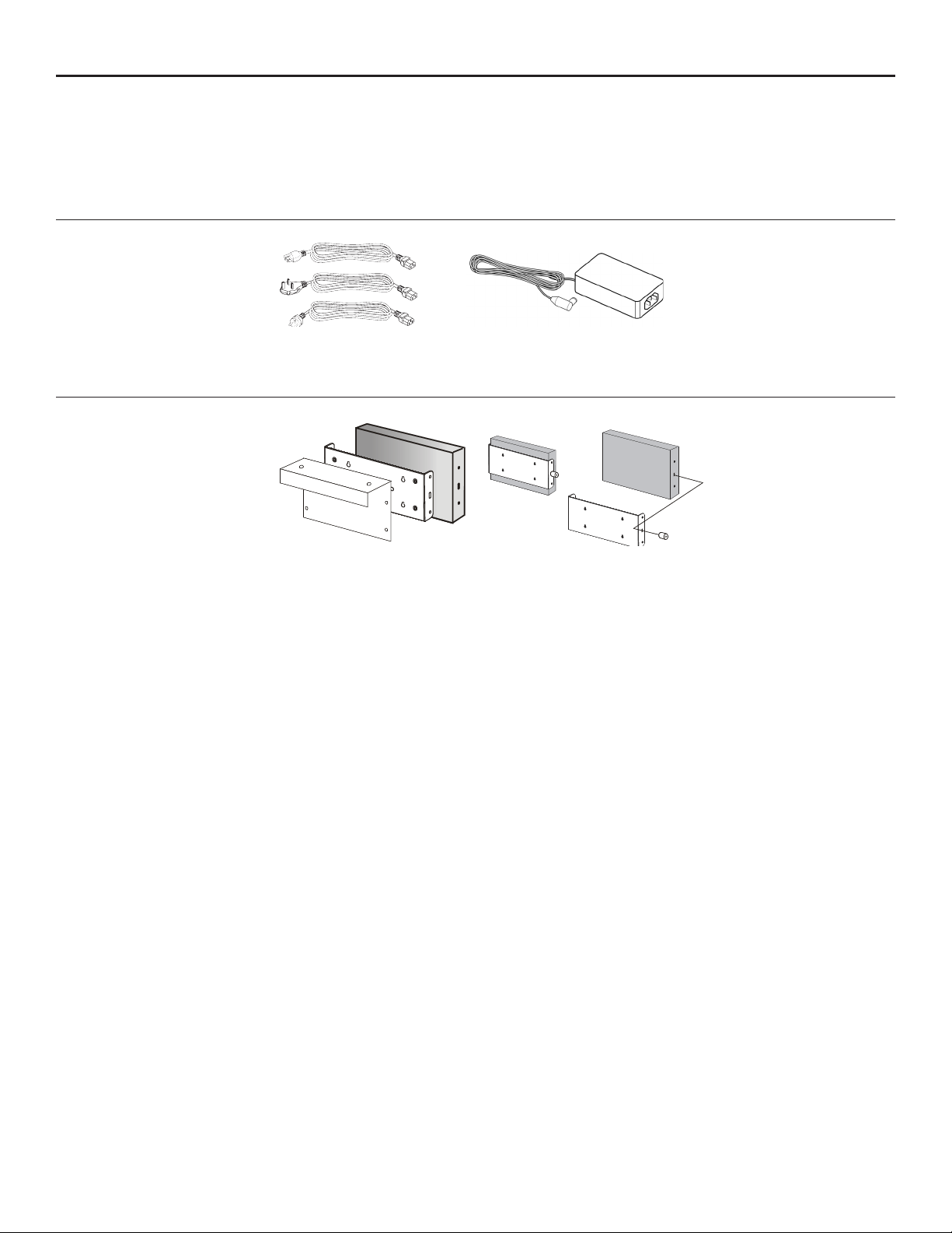
Chapter 4 Setting Up Your Equipment - Model 4500 Indoor Installation
Auxiliary Bracket
Main Mounting
Bracket
HotPoint AP
Unpacking and setup are straightforward. The HotPoint 4501 requires AC power, but can be mount-
ed almost anywhere indoors. Brackets are available to facilitate wall or ceiling mounting. You will
need a Ethernet cable to connect the AP. Congure your HotPoint before installation. Refer to
Chapter 6, or the HotView Pro Reference Guide, for details.
Your AP includes a power supply and three different AC line cords, as shown in Figure 9. Use the
one appropriate for your region.
Figure 9. Indoor AP Power Supply
Mount your HotPoint in a location that will give the best wireless coverage of AP clients. The ac-
cess point does NOT have to be close to its companion HotPort node; in fact, it is better to mount
each unit in a location that is optimum for the RF needs of that unit.
Figure 10. Optional Mounting Brackets
Firetide - Reliable Connectivity Anywhere 9 February 2009
Page 10
Chapter 5 Setting Up Your Equipment - Model 4600 Outdoor Installation
Unpacking and setup are straightforward. Included with your HotPoint 4600 are:
Mounting bracket and hardware, designed to attach the 4600 to a HotPort 6200 family node. If •
you are using an outdoor access point as a Standalone unit, a different mounting kit for this
purpose is available from Firetide.
Two indoor-rated 2.4 GHz omnidirectional staging antennas.•
Weatherproof Ethernet cable, 10-pin to 10-pin, PoE-compatible. •
You should congure your HotPoint before installation. Refer to Chapter 6, or the HotView Pro
Reference Guide, for details.
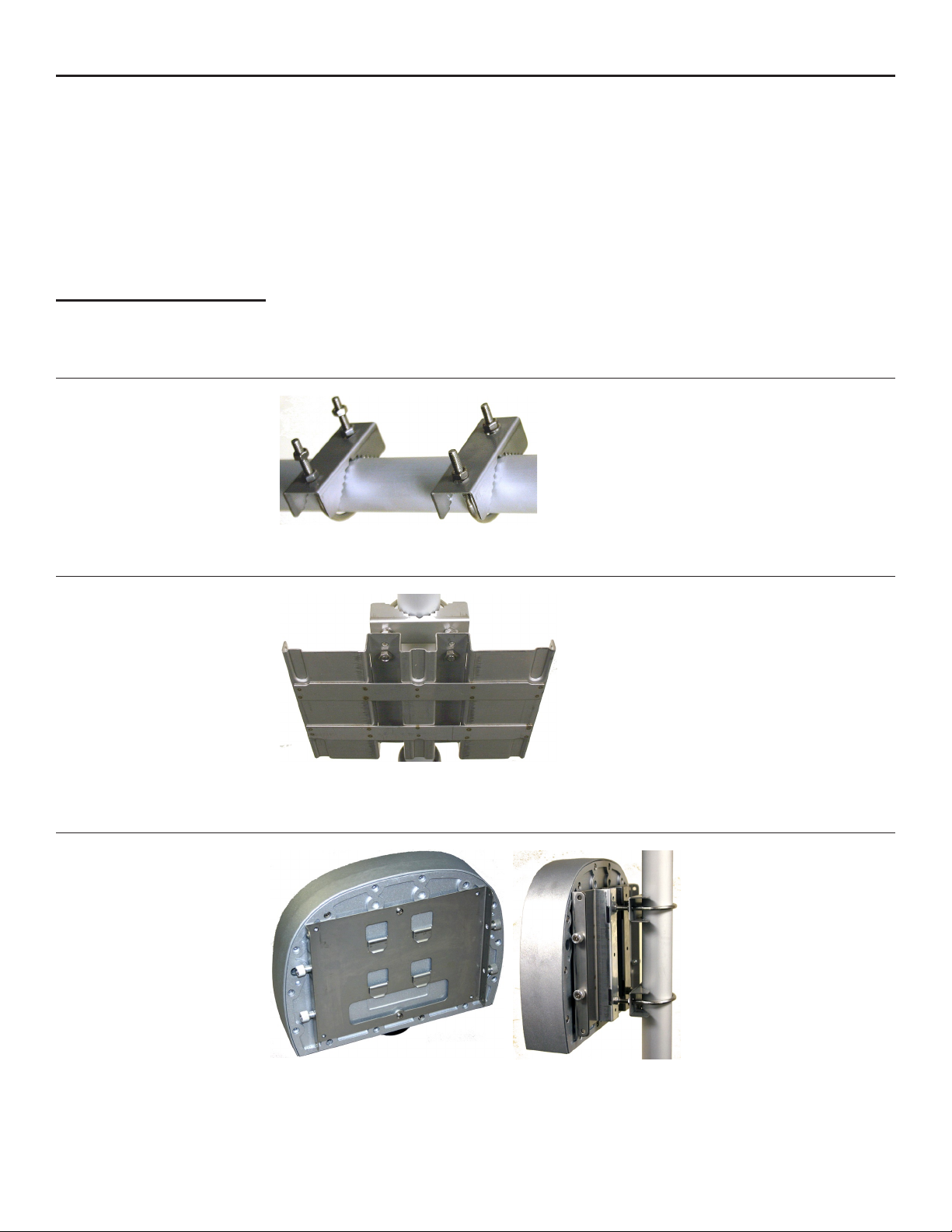
Pole Installation
Figure 11. Pole Clamps
Installation on any pole up to 2 inches is easy. Begin by mounting the supplied U-bolts and ‘claw’
pieces to the pole, using two nuts, as shown in Figure 11. Make the nuts just nger-tight. Depending on the pole diameter, you may need additional nuts, as shown on the lower clamp of Figure 11.
The purpose of the spacer nuts is to prevent the U-bolt legs from protruding too far out beyond the
plate. This will interfere with the AP. If required, place two more spacer nuts on the U-bolts.
Next, attach the plate, using two nuts, as shown in Figure 12. Adjust the nuts to insure that the U-
bolts do not protrude past the fold in the plate. The exact adjustment depends on pole diameter.
Figure 12. Mounting Plate
When the plate is mounted and aligned, tighten all the nuts with a 7/16-inch wrench. Next, slide
the HotPoint onto and downward slightly, so that its tabs on its backing plate (Figure 13) engage
the mounting plate, as shown in Figure 13. Tighten the four knurled nuts on the sides.
Figure 13. AP Bracket Mounting Tabs & Mounted AP
The supplied antennas can be used for initial deployment, but should be replaced after initial
testing with outdoor-rated units of suitable gain and pattern. Complete your installation by connecting the access point to its companion mesh node using the supplied cable, or if you are using
it as a Standalone unit, connect it to your Ethernet backbone.
10 AP User Guide February 2009
Page 11

Chapter 6 Planning Your Software Deployment
Firetide HotPoint access points can be managed and controlled directly via a wired Ethernet connection, or they can be reached via Firetide Mesh Nodes. A combination of the two is possible as
well. These connection methods are known as:
‘Integrated’ operation - each HotPoint is connected to a HotPort mesh router via Ethernet.•
‘Standalone’ operation - the HotPoints are connected directly to the enterprise LAN.•
‘Mixed’ - a combination of the above.•
Note that these terms do NOT refer to the presence (or absense) of a Firetide WLAN Controller or
HotSwitch Mobility Controller.
Integrated Operation
Complete details on the use of HotPoint APs with Firetide’s wireless mesh nodes are given in the
Standalone Operation
HotPoint setup requires only a standard browser. However, browser-based management manages
Understanding APs, AP Groups, VAPs, & VAP Groups
Connect the HotPoint access points to their respective HotPort mesh routers. The HotPorts will
discover the HotPoints automatically. Manage the APs using either HotView or HotView Pro.
HotView Pro Reference Guide, included on your CD. Please read it before proceeding. This manual
describes only the deployment of standalone HotPoint APs, using a browser for conguration.
Connect the HotPoint access points to your enterprise LAN. You will want to connect them one by
one and assign each an IP address. HotPoint nodes can acquire IP addresses from a DHCP server; if
you use this option, you will need to get the assigned IP addresses from the DHCP server.
only one HotPoint (per browser window) at a time; it does not offer a global view of all HotPoints,
or information on statistics and performance. HotView and HotView Pro do; for details on their
use refer to the HotView Pro Reference Guide. Note that HotPoint capabilities are the same regardless of management method; the only difference is convenience, performance statistics, and error
logs.
Firetide APs support virtualization, so that one physical platform can support multiple virtual in-
stances of an access point.
An AP is a physical system - a computer and a radio - which can implement multiple “virtual” ac-
cess points. Virtual Access Points, or VAPs, are the logical systems that wireless clients actually see
and connect to.
Each HotPoint node offers a range of network as well as radio conguration options. The commands
which control these features and options are grouped logically. This makes it easy to manage large
collections of physical nodes and virtual APs, once you understand the concepts.
Access Points (AP) - certain parameters, such as radio settings, are specic to the hardware on
each particular physical node.
Virtual Access Points (VAP) - HotPoints support Virtual Access Points.
VAP Groups - VAPs are grouped together for management purposes. You will create at least one
VAP group, with SSID, encryption, and other parameters. This is the ‘access point’ that will appear
to wireless clients.
Access Point Groups - In some cases, you may want to grant management access to some nodes
to one person or persons, and other nodes to other persons. This can be done using Access Point
Groups. Each HotPoint may be assigned to an Access Point Group, or AP group. You can specify
different user names and passwords for each group.
All HotPoint commands are grouped based on whether they affect settings on a physical node, a VAP
Group, an AP Group, or an individual VAP.
Firetide - Reliable Connectivity Anywhere 11 February 2009
Page 12
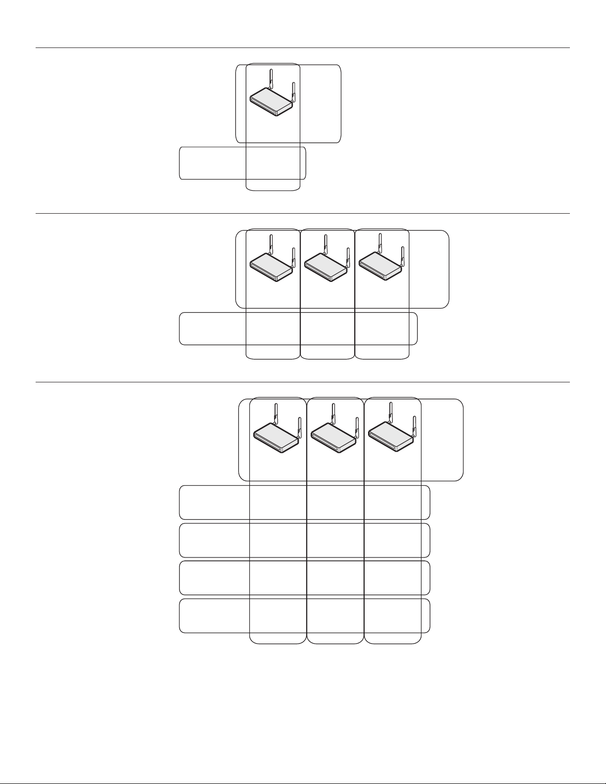
Figure 14 shows how the various domains relate to each other.
Name
IP Address
Firewall
VPN
VAP Groups
VAP Group A
VAP IP Address
DHCP / DNS
NA T
SSID
Encryption
MAC Address Access
AP Group
Login
Password
AP
VA P
Name
IP Address
Firewall
VPN
Name
IP Address
Firewall
VPN
Name
IP Address
Firewall
VPN
VAP Groups
VAP Group A
VAP IP Address
DHCP / DNS
NA T
VAP IP Address
DHCP / DNS
NA T
VAP IP Address
DHCP / DNS
NA T
SSID
Encryption
MAC Address Access
AP Group
Login
Password
AP APAP
VA P VA PVA P
Name
IP Address
Firewall
VPN
Name
IP Address
Firewall
VPN
Name
IP Address
Firewall
VPN
VAP Groups
VAP Group A
VAP Group B
VAP IP Address
DHCP / DNS
NA T
VAP IP Address
DHCP / DNS
NA T
VAP IP Address
DHCP / DNS
NA T
VAP IP Address
DHCP / DNS
NA T
VAP IP Address
DHCP / DNS
NA T
VAP IP Address
DHCP / DNS
NA T
SSID
Encryption
MAC Address Access
SSID
Encryption
MAC Address Access
VAP Group C
VAP IP Address
DHCP / DNS
NA T
VAP IP Address
DHCP / DNS
NA T
VAP IP Address
DHCP / DNS
NA T
SSID
Encryption
MAC Address Access
AP Group
Login
Password
AP APAP
VAP Group D
VAP IP Address
DHCP / DNS
NA T
VAP IP Address
DHCP / DNS
NA T
VAP IP Address
DHCP / DNS
NA T
SSID
Encryption
MAC Address Access
VA P VA PVA P
VA P VA PVA P
VA P VA PVA P
VA P VA PVA P
Figure 14. Matrix of Physical and Logical APs - Simple
Figure 15 shows more complex arrangements of multiple APs and multiple Virtual APs.
Figure 15. Three-AP Network
Figure 16 shows a three-AP, three-VAP conguration. You can have multiple VAPs per physical AP.
Figure 16. Large AP Matrix
12 AP User Guide February 2009
Page 13

Basic Setup Sequence
The basic sequence of steps in setting up a Firetide HotPoint access point are summarized here,
then shown in detail in the following pages.
If you are installing a new Firetide-based wireless network, begin by installing the HotPort Mesh
nodes, and the HotView or HotView Pro mesh management software, before installing any HotPoint
APs. Refer to the HotView Pro Reference Guide for details.
Congure your PC IP address to access the HotPoint.1.
Assign a management IP address to each HotPoint. The default address options are shown 2.
in Table 2. The IP address you pick should be reachable from your computer. It does not
need to be on the same subnet as the management address of the Firetide mesh. (Note that
if you are using DHCP for Standalone access points, you will need to capture the IP address
assigned by the DHCP server to each HotPoint.)
Table 2. Default IP Addresses
HotPoint Connection Method
via HotPort node
Standalone
Log in to the AP.3.
Set the Country Code.4.
Change the default password.5.
Rename the AP. A name based on the AP’s location is a good choice.6.
Set the radio settings (channel, etc) for each physical AP.7.
Repeat these steps for all access points. Then:
Create one or more VAP Groups, using the VAP Group Conguration command. You must have 8.
at least one group, even if you only have one AP.
Use the VAP Conguration command to congure those VAP features which are controlled per 9.
physical AP. (DHCP, DNS, NAT)
Use the VAP Group conguration command to assign the SSID, security, and other features 10.
for the entire VAP group.
Table 3 gives a summary of all of the major commands and options available on the HotPoint APs, organized by logical group.
Table 3. Summary of Commands by Logical Group
DHCP Server Default IP Address
don’t-care none
DHCP available as assigned by DHCP
no DHCP available 192.168.224.160
Physical AP AP Group VAP Conguration VAP Group Conguration
AP Name Membership DHCP Server
DHCP Service IP address
VAP IP address
AP Mgmt IP address
/ DHCP client
Performance Statistics NAT VLAN
Radio Settings: ch, mode, RF
power, beacon
Firewall Encryption
VPN MAC address access
Country Code Intracell blocking
Reboot / Reset User data rate control
Import & Apply IAPP
Guest Login
Admin Login
DNS Broadcast SSID
WDS (new group creation only)
SSID suppression
DTIM, RTS/CTS,
fragmentation
Firetide - Reliable Connectivity Anywhere 13 February 2009
Page 14
Chapter 7 Software Conguration
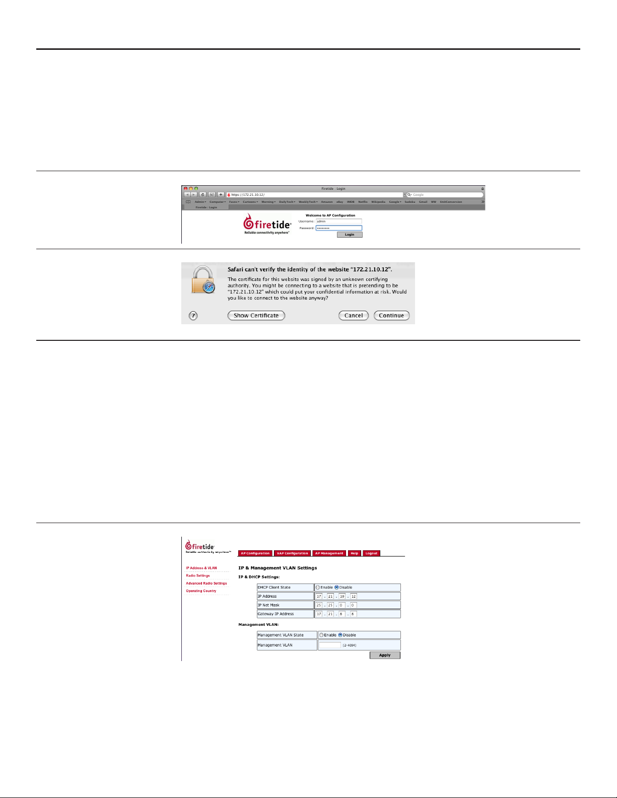
Firetide HotPoint access points, when used as Standalone APs, can be managed via a secure
(HTTPS) browser connection. Firefox, Mozilla, Safari, and Internet Explorer are supported. To connect via a browser, use the URL:
https://192.168.224.160/ (or other IP address, as assigned.)
You will see a screen similar to the one shown in Figure 1. If you don’t, make sure your typed
https, not http. Log in using the default values, admin and retide. Depending on your browser’s
security settings, you may receive a warning message, as shown in Screen 2. Click through and
complete the login process.
Screen 1. Browser Welcome Screen
Screen 2. Browser Security Warning
Initial Command Screen
The ‘home page’ for browser-based management of the HotPoint AP is shown in Figure 17. It
shows a summary of the available Virtual APs. If the AP is new, no VAPs will be shown; if the unit
has already been placed into service, you will see a list of existing VAPs (as in this case). Model
4100/4200 and Model 4500/4600 have slightly different settings in some screens, but the overall
setup is the same.
You will need to congure both ‘physical’ parameters, such as unit IP address and radio settings,
and ‘virtual’ parameters, such as SSID and encryption.
The setup sequence for each physical unit is:
Set the Country Code. You should always do this immediately after any factory reset. The 1.
radio operates in a very low-power mode until the country code is set.
Change the IP address. On new or reset units, the IP address is set to 192.168.224.160. You 2.
should change this to an address that ts your overall IP addressing scheme.
Set the radio channel, power, and related parameters.3.
Figure 17. Command Screen
The setup sequence for each virtual access point (VAP) is:
Create the VAP Group, or select an existing one.4.
Congure the VAP.5.
Congure the VAP Group.6.
14 AP User Guide February 2009
Page 15
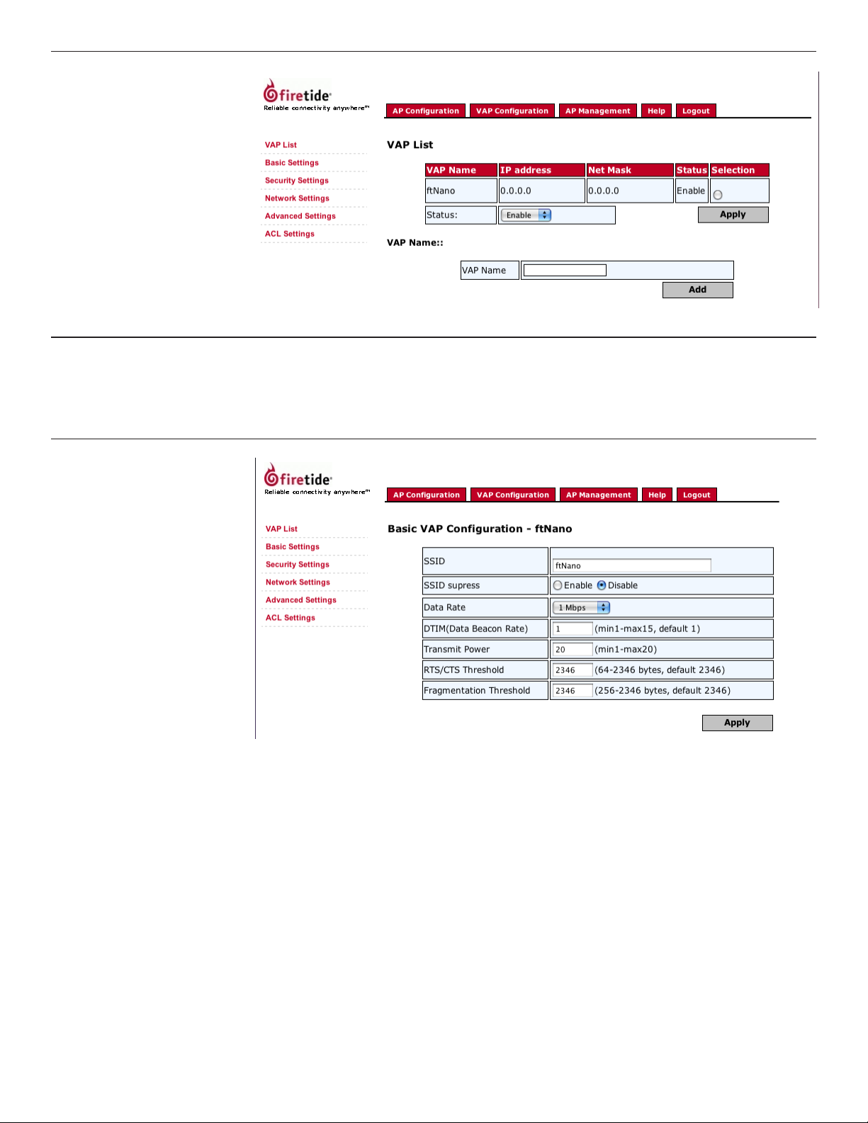
Screen 18. Conguring VAP Groups
Basic VAP Settings
Basic VAP Settings include the SSID, maximum data rates, maximum power, and other SSID pa-
rameters. Note that the maximum power level will be less that 26 dBm (400 mW) if you are on a
channel where reduced power is required, or if you have reduced power on the main radio settings
page. (It is possible to set some VAPs to use less power than the maximum, while leaving other
VAPs at full power.) These parameters are set as shown in Screen 3.
Screen 3. VAP Basic Settings
Firetide - Reliable Connectivity Anywhere 15 February 2009
Page 16
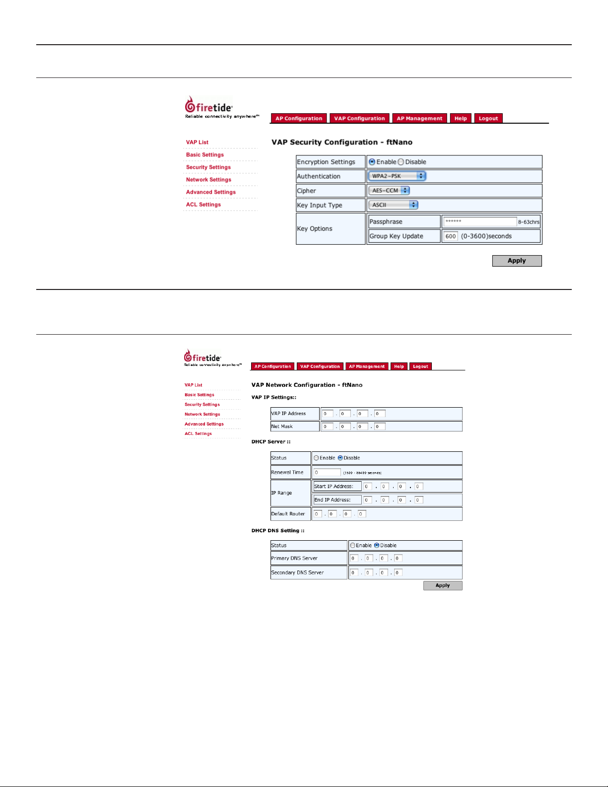
VAP Security Settings
This is done with the IP & VLAN command under the Management command, as shown in Screen
4. Enable security, then select the desired type and parameters from the available choices.
Screen 4. VAP Security Settings
Network Settings
Each VAP has its own network settings, as shown in Screen 5. A VAP has a unique IP address; it is
this address that clients see. The VAP IP address does not need to be on the same subnet as the
physical AP IP address. The physical AP IP address is used for management only.
Screen 5. VAP Network Settings
16 AP User Guide February 2009
Page 17
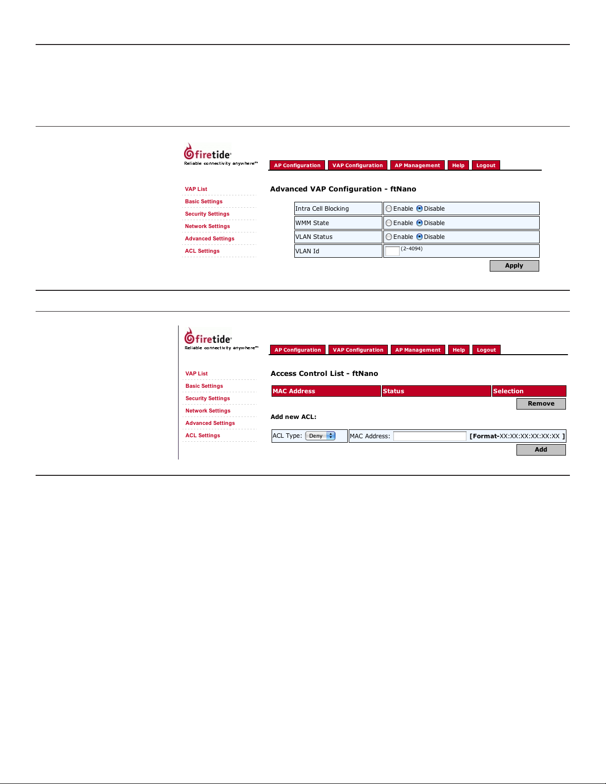
VAP Advanced Settings
In some applications, you may wish to use certain advanced features:
Intra-cell blocking prevents clients on the same AP from ‘seeing’ each other. This provides ad-•
ditional security, especially for public hotspots.
WMM provides QoS support for multimedia applications.•
VLANs provide a method of isolating trafc at layer 2.•
Screen 6. VAP Advanced Settings
Access Control Lists for VAPs
For each VAP, you can dene access control lists based on MAC addresses.
Screen 7. VAP ACL Setup
Firetide - Reliable Connectivity Anywhere 17 February 2009
Page 18
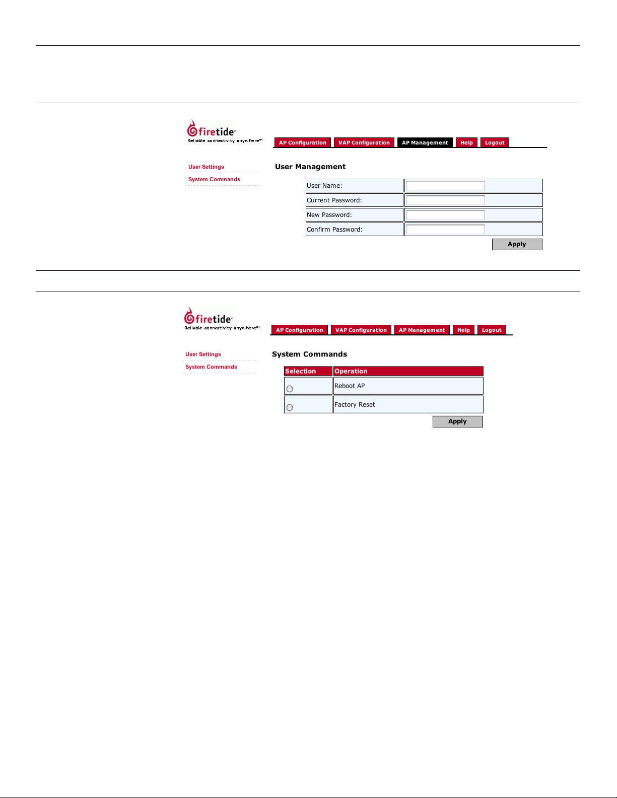
AP Management - User Settings
The AP Management tab allows you to dene administrative access rights for the physical AP. You
can also remotely reboot an AP, and remotely restore it to factory default settings. (Keep in mind
that resetting to factory defaults will change the IP address to 192.168.224.160. You may need to
modify your computer settings to reach the node at this address.)
Screen 8. AP Management User Settings
AP Management - System Commands
The AP can be rebooted or factory-reset via this command
Screen 19. AP System Commands
18 AP User Guide February 2009
Page 19

Appendix A Specications
Common Specications
These tables describes the technical capabilities of the nodes. Various country restrictions may further limit available choices.
Model Use
4100 Indoor, Worldwide, 2.4/4.9/5 GHz, 400 mW max
4200 Outdoor, Worldwide, 2.4/4.9/5 GHz, 400 mW max
4500 Indoor, Worldwide, 2.4 GHz, 400 mW max
4600 Outdoor, Worldwide, 2.4 GHz, 400 mW max
Bands (GHz) Frequency (GHz) Restrictions
Agency Certications
802.11a
(4100, 4200)
802.11b/g
(all models)
Bands (GHz) Max TX Power
802.11a, 5.725-5.825 UNII-3
5.470-5.735 UNII
5.25-5.36 M UNII-2
5.15-5.25 UNII-1
802.11b 24 dBm/all rates
802.11g 26dBm/6-24Mbps
Contact your Firetide dealer for product availability and certications for your country.
5.15-5.25, 5.25-5.35, 5.725-5.825
4.9-5.090
4.94-4.990
5.470-5.725 ETSI 301.893, U-NII
2.412-2.484
26dBm/6-24Mbps
26dBm/36Mbps
24dBm/48Mbps
23dBm/54Mbps
23 dBm/6-54 Mbps
23 dBm/6-54 Mbps
17 dBm/6-54 Mbps
26dBm/36Mbps
25dBm/48Mbps
24dBm/54Mbps
Japan only
US Public Safety
Firetide - Reliable Connectivity Anywhere 19 February 2009
Page 20

Model 4100 Indoor Unit Specications
Enclosure
Two RP-SMA antenna connectors, with 1 pair of 5 dBi 2.4 GHz omnidirectional antennas.
One DC power connector.
One RJ-45 Ethernet connector, CSMA/CD 10/100 autosense.
System indicator LEDs: power, status.
Weight: 10 oz. (270 g).
Dimensions: 6” x 4.75” x 1” (150 x 120 x 25 mm).
Power
AC power adapter: 100-240 VAC, 50/60 Hz input; 12 VDC, 1.5A rated output.
Environmental Specications
Storage temperature: -40º C to +70º C.
Humidity (non-condensing): 10% to 90%.
Storage humidity (non-condensing): 5% to 95%.
Maximum altitude 15,000 feet (4600 meters).
Plastic enclosure.
DC Input: 11-16 VDC, 0.7 A at 12 VDC.
Operating temperature: 0º C to +60ºC.
Model 4500 Indoor Unit Specications
Enclosure
System indicator LEDs (power, uplink, access, status).
Two antenna connectors: SMA, reverse polarity.
Power connector.
One RJ-45 Ethernet connector, CSMA/CD 10/100 autosense.
Reset button (recessed).
Security slot for physical locking device.
Weight: 2.1 lbs (.95 Kg) without external transformer.
Dimensions: 9.00 in x 5.84 in x 1.07 in (22.85 cm x 14.83 cm x 2.71 cm).
Power
AC power adapter: 100-240 VAC, 50/60 Hz input.
Environmental Specications
Storage temperature: -20º C to +70º C.
Humidity (non-condensing): 10% to 90%.
Storage humidity (non-condensing): 10% to 90%.
Maximum altitude 15,000 feet (4600 meters).
Plenum rated per UL2043.
DC Input: 5 VDC, 2.0 A.
Operating temperature: -20º C to +60ºC.
20 AP User Guide February 2009
Page 21

Model 4200 Outdoor Unit Specications
Enclosure
One built-in antenna, one N-type antenna connector for optional antenna.
One weatherproof Ethernet connector, CSMA/CD 10/100 autosense, PoE-compliant per 802.3af.
System indicator LEDs (power, status, align).
Weight: 2 lbs (0.9 Kg) without bracket.
Dimensions: 7.8” x 8.3” x 2.4” (195 x 210 x 60 mm).
Bracket for pole and wall mounting.
One weatherized Ethernet transition cable with watertight RJ-45 coupling.
Power
PoE PSE module: AC Input 90-240 VAC, 50-60 Hz, 0.15A.
Unit power dissipation < 9W.
Environmental Specications
Storage temperature: -40º C to +70º C.
Humidity (non-condensing): 10% to 90%.
Storage humidity (non-condensing): 5% to 95%.
Maximum altitude 15,000 feet (4600 meters).
Cast aluminum NEMA-4X/IP66 enclosure.
Unit power is via 802.3af Power-over-Ethernet.
Operating temperature: -40º C to +60ºC.
Model 4600 Outdoor Unit Specications
Enclosure
Two N-type antenna connectors.
One weatherproof Ethernet connector, CSMA/CD 10/100 autosense, PoE-compliant per 802.3af.
System indicator LEDs (power, status).
One weatherized Ethernet cable with watertight RJ-45 coupling.
Power
Unit power is via 802.3af Power-over-Ethernet.
PoE PSE module: AC Input 90-240 VAC, 50-60 Hz, 0.15A.
Unit power dissipation < 9W.
Optional external power supply: 100-240 VAC, 50/60 Hz
Environmental Specications
Storage temperature: -40º C to +70º C.
Humidity (non-condensing): 10% to 90%.
Storage humidity (non-condensing): 10% to 90%.
Maximum altitude 15,000 feet (4600 meters).
Cast aluminum NEMA-4X/IP66 enclosure.
12-18 VDC, or PoE. Do not connect both.
Operating temperature: -20º C to +60ºC.
Firetide - Reliable Connectivity Anywhere 21 February 2009
Page 22

Appendix B Regulatory Notices
FCC Part 15 Note
FCC Class B Notice
FCC Radiation Exposure
Modications
Installation
Canadian Compliance
Statement
Firetide 4100 and 4200 devices are certied to the requirements of RSS-210 for 2.4 GHz spread
These devices comply with Part 15 of the FCC Rules. Operation is subject to the following two con-
ditions:
This device may not cause harmful interference. •
This device must accept any interference received, including interference that may cause unde-•
sired operation.
This equipment has been tested and found to comply with the limits for a Class B digital device,
pursuant to Part 15 of the FCC Rules. These limits are designed to provide reasonable protection
against harmful interference in a residential installation. This equipment generates, uses and can
radiate radio frequency energy and, if not installed and used in accordance with the instructions,
may cause harmful interference to radio communications. However, there is no guarantee that
interference will not occur in a particular installation. If this equipment does cause harmful interference to radio or television reception, which can be determined by turning the equipment off
and on, the user is encouraged to try to correct the interference by one or more of the following
measures:
Reorient or relocate the receiving antenna.•
Increase the separation between the equipment and receiver.•
Connect the equipment into an outlet on a circuit different from that to which the receiver is •
connected.
Consult the dealer or an experienced radio/TV technician for help.•
To ensure compliance with the FCC’s RF exposure limits, the antenna used for this transmitter must
be installed to provide a separation distance of at least 70 cm from all persons and must not be
co-located or operated in conjunction with any other antenna or transmitter. Installers and end
users must follow these installation instructions.
Any modications made to this device that are not approved by Firetide, Inc. may void the author-
ity granted to the user by the FCC to operate this equipment.
Antenna(s) for the Model 4200 outdoor unit must be installed by a qualied professional. Opera-
tion of the unit with non- approved antennas is a violation of U.S. FCC Rules, Part 15.203(c), Code
of Federal Regulations, Title 47.
This Class B Digital apparatus meets all the requirements of the Canadian Interference-Causing
Equipment Regulations. Cet appareil numerique de la classe B respecte les exigences du Reglement
sur le material broilleur du Canada.
spectrum devices. The use of this device in a system operating either partially or completely outdoors may require the user to obtain a license for the system according to the Canadian regulations. For further information, contact your local Industry Canada ofce.
NCC Statement
一、經型式認證合格之低功率射頻電機,非經許可,公司、商號或使用者均不得擅自變更頻率、加大功率或變更原設計之特性及功能。
二、低功率射頻電機之使用不得影響飛航安全及干擾合法通信;經發現有干擾現象時,應立即停用,並改善至無干擾時方得繼續使用。
前項合法通信,指依電信法規定作業之無線電通信。
低功率射頻電機須忍受合法通信或工業、科學及醫療用電波輻射性電機設 備之干擾。
22 AP User Guide February 2009
Page 23

Appendix C Ethernet Wiring
Custom cables may be constructed following these wiring connections.
Table 4. Circular, Watertight IP66-Rated Pin Descriptions
Connector Pin # Wire Color Port Pin #
1 White/Orange 1
2 Orange 2
3 White/Green 3
4 Blue 4
5 White/Blue 5
6 Green 6
7 White/Brown 7
8 Brown 8
Drain Wire 9
Drain Wire 10
Table 5. RJ-45 Connector Pin Descriptions
Pin # Signal Description
1 TXD+ TX Data 10 BaseT/100 BaseTX
2 TXD- TX Data 10 BaseT/100 BaseTX
3 RXD+ RX Data 10 BaseT/100 BaseTX
4 PoE+ Power Input 5 VDC to 48 VDC +
5 PoE+ Power Input 5 VDC to 48 VDC +
6 RXD- RX Data 10 BaseT/100BaseTX
7 PoE- Power Input 5 VDC to 48 VDC -
8 PoE- Power Input 5 VDC to 48 VDC -
Appendix D Reset Procedure
Firetide Access Points may be reset to factory parameters. This is useful when returning a unit from
eld service or in recovering a unit you cannot communicate with.
To reset a unit, apply power and wait for the unit to fully boot. This takes 60 to 90 seconds. The
‘status’ LED will glow steady green when the unit is booted.
For indoor units, use a paperclip to press and release the reset button via the small hole on the
back of the unit.
For outdoor units, remove the small cover from the reset switch and activate the reset button.
Wait for the units to reboot before removing power. The status LED will glow green again when it
is safe to remove power.
Firetide - Reliable Connectivity Anywhere 23 February 2009
Page 24

Firetide, Inc.
140 Knowles Avenue
Los Gatos, CA 95032 USA
Copyright Notice: ©2009 Firetide, Inc. All rights reserved.
Trademarks: Firetide, the Firetide logo, Instant Mesh Networks, HotPort, HotPoint, and HotClient are trademarks of
Firetide, Inc. All other trademarks are the property of their
respective owners.
 Loading...