

Firetide HotPort 6100 Series, HotPort 6102, HotPort 6200 Series, HotPort 6101, HotPort 6201 Hardware Installation Manual
...
Hardware Installation Guide
HotPort
HotPort Series 6000
Indoor and Outdoor Wireless Mesh Nodes
Manual Revision 1.06 012909
The contents of this Installation Guide are subject to change without notice.
Please refer to the Firetide partners web site, partners.firetide.com, for current versions.
Series 6200 - Outdoor NodeSeries 6100 - Indoor Node
Firetide Limited End User Product Warranty
Pursuant to all provisions described herein, Firetide hardware products and
Firetide antennas are warranted for one (1) year from the date of purchase
against defects in the build materials and workmanship. Firetide does not
warrant that the Products will meet any requirements or specifications of
any End User Customer. This warranty applies to the entire Firetide product,
including the AC power adapter.
Pursuant to all provisions described herein, Firetide sof tware products are
warranted for ninety (90) days from the date of purchase against defects in
the build materials and workmanship. Firetide also warrants that the Software will materially conform to the documentation supplied by Firetide with
the Software. In the event that the Software fails to materially conform to
the documentation and an authorized Firetide reseller is notified in writing
of such failure within the warranty period, Firetide or its reseller shall use
commercially reasonable efforts to promptly correct the nonconformity.
Firetide does not warrant that the use of the Software will be uninterrupted
or error free.
The above warranties are void if the alleged defect cannot be verified by
Firetide or if, as determined by Firetide, the product failure was due to tampering, abuse, misuse, accident, shipping, handling, or storage; or if the
product has been installed, used, or maintained in a manner not described
in the product user manual; or if the product has been altered in any way;
or if product serialization has been altered. Any attempt to disassemble or
repair the product by anyone other than Firetide immediately voids this
warranty.
This warranty applies only to the original End User purchaser of the product
and may not be transferred to any other individual or entity.
THE FOREGOING ARE THE EXCLUSIVE WARRANTIES APPLICABLE TO THE PRODUCT INCLUDING THE SOFTWARE, AND THE EXCLUSIVE REMEDY FOR DEFECTS
IN THE PRODUCT. FIRETIDE DISCLAIMS ALL OTHER WARRANTIES, WHETHER
EXPRESS, IMPLIED, STATUTORY OR OTHERWISE, INCLUDING BUT NOT LIMITED
TO IMPLIED WARRANTIES OF MERCHANTABILITY, NON-INFRINGEMENT OR FIT-
NESS FOR A PARTICULAR PURPOSE. SOME LAWS DO NOT ALLOW THE EXCLUSION OF IMPLIED WARRANTIES SO TO THAT EXTENT THIS LIMITATION MAY NOT
APPLY TO YOU.
In no event will Firetide be liable for any special, incidental, consequential,
punitive or indirect damages whatsoever (including, without limitation,
damages for loss of profits, business interruption, loss of information, or
other pecuniary loss) arising out of the use or inability to use the product
or the performance, interruption or failure of the product, irrespective of
the cause of action, even if Firetide has been advised of the possibility of
such damages. Firetide’s cumulative liability for all claims arising out of or
in connection with this warranty will not exceed the amount paid by the
original End User purchaser to purchase the product. The amounts payable
for the product are based in part on these limitations and these limitations
shall apply notwithstanding the failure of essential purpose of any remedy.
Some jurisdictions do not allow the exclusion or limitation of incidental or
consequential damages, so to that extent the above limitations or exclusions may not apply to you.
By using the product the original End User purchaser agrees to and is bound
by these terms and conditions.
In the event that a product fails to meet this warranty and Firetide’s authorized reseller is notified in writing of such failure within the warranty period, Firetide shall, at its own discretion, either repair the product or replace
it with the same or a functionally-equivalent product free of charge. Replacement products may contain refurbished materials in whole or in part.
Firetide will honor this warranty provided the product is returned through
an authorized Firetide reseller or dealer with shipping charges prepaid,
along with a proof of purchase describing the original purchase date and
product serial numbers if applicable. The authorized reseller must acquire a
Return Materials Authorization (RMA) number from Firetide prior to returning any product. Firetide does not accept shipments of defective products
without shipping charges prepaid.
Safety Instructions
The HotPort outdoor wireless mesh node must be installed by a qualified professional such as a licensed electrician. Failure to install this
equipment properly may result in equipment damage and personal injury or death.
This symbol is intended to alert the user to the presence of non-insulated dangerous voltage that may be
of sufficient magnitude to constitute a risk of lethal
electric shock to persons.
Copyright Notice: ©2003-2007 Firetide, Inc. All rights reserved.
Trademarks: Firetide, the Firetide logo, Instant Mesh Networks, HotPort, and HotPoint are trademarks of Firetide, Inc. All other trademarks are the property of their respective owners.
2 HotPort Series 6000 Mesh Nodes
This symbol is intended to alert the user to the presence of important operating, maintaining and servicing instructions in the literature accompanying the
HotPort node. Failing to comply with this instruction
may result in electrical shock.
This symbol is intended to alert the user to the presence of important operating, maintaining and servicing instructions in the literature accompanying the
HotPort node. Failing to comply with this instruction
may result in a hazard.
January 2009

Contents
HotPort Node Installation . . . . . . . . . . . . . . . . . . . . . . . . . . . . . . . . . . . . . . . . . . . . . . . . . . . . . . . . . . . . . . . . . . . . . . . . . . . . . . . . . . . . . .5
Package Contents ..........................................................................................5
Planning Your Installation . . . . . . . . . . . . . . . . . . . . . . . . . . . . . . . . . . . . . . . . . . . . . . . . . . . . . . . . . . . . . . . . . . . . . . . . . . . . . . . . . . . . . .7
Staging Considerations ......................................................................................7
Antenna Placement .........................................................................................7
Required Tools and Supplies ..................................................................................7
Indoor Node Installation .......................................................................................8
Outdoor Node Installation . . . . . . . . . . . . . . . . . . . . . . . . . . . . . . . . . . . . . . . . . . . . . . . . . . . . . . . . . . . . . . . . . . . . . . . . . . . . . . . . . . . . . .9
Preparing the Unit.......................................................................................... 9
Preparing the Site for Mounting ...............................................................................9
Safety Considerations . . . . . . . . . . . . . . . . . . . . . . . . . . . . . . . . . . . . . . . . . . . . . . . . . . . . . . . . . . . . . . . . . . . . . . . . . . . . . . . . . . . . . .9
Weatherproofing . . . . . . . . . . . . . . . . . . . . . . . . . . . . . . . . . . . . . . . . . . . . . . . . . . . . . . . . . . . . . . . . . . . . . . . . . . . . . . . . . . . . . . . . . .9
Preparing Earth Ground .....................................................................................9
Mounting the Antennas..................................................................................... 10
Mounting Guidelines . . . . . . . . . . . . . . . . . . . . . . . . . . . . . . . . . . . . . . . . . . . . . . . . . . . . . . . . . . . . . . . . . . . . . . . . . . . . . . . . . . . . . .10
Mounting the Universal Bracket .............................................................................. 11
Removing the Bracket . . . . . . . . . . . . . . . . . . . . . . . . . . . . . . . . . . . . . . . . . . . . . . . . . . . . . . . . . . . . . . . . . . . . . . . . . . . . . . . . . . . . .11
Choosing a Mounting Location ...............................................................................11
Wall Mounting . . . . . . . . . . . . . . . . . . . . . . . . . . . . . . . . . . . . . . . . . . . . . . . . . . . . . . . . . . . . . . . . . . . . . . . . . . . . . . . . . . . . . . . . . . .11
Pole Mounting . . . . . . . . . . . . . . . . . . . . . . . . . . . . . . . . . . . . . . . . . . . . . . . . . . . . . . . . . . . . . . . . . . . . . . . . . . . . . . . . . . . . . . . . . . .11
Using Mounting Straps .....................................................................................12
Mounting the Node ........................................................................................13
Connecting Cables......................................................................................... 14
Power Connection . . . . . . . . . . . . . . . . . . . . . . . . . . . . . . . . . . . . . . . . . . . . . . . . . . . . . . . . . . . . . . . . . . . . . . . . . . . . . . . . . . . . . . . .14
Connecting Ethernet Cables .................................................................................15
Building a Custom Ethernet Cable ............................................................................. 15
Typical Connections........................................................................................ 16
Adding a HotPoint AP to a HotPort Node ........................................................................17
Appendix A - Contacting Firetide . . . . . . . . . . . . . . . . . . . . . . . . . . . . . . . . . . . . . . . . . . . . . . . . . . . . . . . . . . . . . . . . . . . . . . . . . . . . . . . .19
Appendix B - Connector Wiring . . . . . . . . . . . . . . . . . . . . . . . . . . . . . . . . . . . . . . . . . . . . . . . . . . . . . . . . . . . . . . . . . . . . . . . . . . . . . . . . .20
HotPort Outdoor Node Ethernet Transition Cable Pin Descriptions ....................................................20
HotPort Outdoor Node AC Power Connector......................................................................20
HotPort Outdoor Node DC Power Connector...................................................................... 21
Custom Power Cables....................................................................................... 21
HotPort Indoor Node DC Power Connector.......................................................................22
Appendix C - Specifications . . . . . . . . . . . . . . . . . . . . . . . . . . . . . . . . . . . . . . . . . . . . . . . . . . . . . . . . . . . . . . . . . . . . . . . . . . . . . . . . . . . .23
Common Specifications .....................................................................................23
Wireless Interface . . . . . . . . . . . . . . . . . . . . . . . . . . . . . . . . . . . . . . . . . . . . . . . . . . . . . . . . . . . . . . . . . . . . . . . . . . . . . . . . . . . . . . . .23
Series 6200 Outdoor Unit Specifications . . . . . . . . . . . . . . . . . . . . . . . . . . . . . . . . . . . . . . . . . . . . . . . . . . . . . . . . . . . . . . . . . . . . . . . . 24
Series 6100 Indoor Unit Specifications .........................................................................24
Appendix D - Regulatory Notices . . . . . . . . . . . . . . . . . . . . . . . . . . . . . . . . . . . . . . . . . . . . . . . . . . . . . . . . . . . . . . . . . . . . . . . . . . . . . . . .25
USA . . . . . . . . . . . . . . . . . . . . . . . . . . . . . . . . . . . . . . . . . . . . . . . . . . . . . . . . . . . . . . . . . . . . . . . . . . . . . . . . . . . . . . . . . . . . . . . . . . .25
Canadian Compliance Statement .............................................................................25
Appendix E - Waterproofing Instructions . . . . . . . . . . . . . . . . . . . . . . . . . . . . . . . . . . . . . . . . . . . . . . . . . . . . . . . . . . . . . . . . . . . . . . . . . .26
January 2009
Firetide Instant Mesh Networks 3

Caution! Risk of electric shock!
POWER LINES CAN BE LETHAL
Do not install the HotPort outdoor mesh node where possible contact with power lines can be made. Antennas, poles, towers, guy
wires, or cables may lean or fall and contact these lines. People may
be injured or killed if they are touching or holding any part of the
equipment when it contacts electric lines. Make sure there is NO
possibility that equipment or personnel can come in contact directly
or indirectly with power lines.
ASSUME ALL OVERHEAD LINES ARE POWER LINES
The horizontal distance from a tower, pole or antenna to the nearest
power line should be at least twice the total length of the pole/antenna combination. This will ensure that the pole will not contact
power if it falls either during or after installation.
SURVEYING THE SITE
Look over the entire site before beginning any installation and anticipate possible hazards. Never assume anything without checking
it out for yourself! Don’t take shortcuts!
TO AVOID FALLING, USE SAFE PROCEDURES WHEN WORKING AT
HEIGHTS ABOVE GROUND
Select equipment locations that will allow safe and simple in-•
stallation.
Don’t work alone. A friend or co-worker can save your life if an •
accident happens.
Don’t attempt repair work when you are tired. Not only will •
you be more careless, but your primary diagnostic tool -
deductive reasoning - will not be operating at full capacity.
Use approved non-conducting ladders, shoes, and other safety •
equipment. Make sure all equipment is in good repair.
If a tower or pole begins falling, don’t attempt to catch it. Stand •
back and let it fall.
If anything such as a wire or pole does come in contact with a •
power line, DON’T TOUCH IT OR ATTEMPT TO MOVE IT. Instead,
save your life by calling the power company.
Don’t attempt to erect antennas or towers on windy days.•
MAKE SURE ALL TOWERS AND POLES ARE SECURELY GROUNDED, •
AND ELECTRICAL CABLES CONNECTED TO ANTENNAS HAVE LIGHTNING ARRESTORS. This will help prevent fire damage or human
injury in case of lightning, static build-up, or short circuit within
equipment connected to the antenna. The HotPort outdoor node
has built-in lightning protection. Be sure that any other equipment connected to the HotPort node also has the same level of
protection.
The base of the antenna pole or tower must be connected direct-•
ly to the building protective ground or to one or more approved
grounding rods, using 10 AWG ground wire and corrosion-resistant connectors.
Refer to the National Electrical Code for grounding details.•
IF AN ACCIDENT SHOULD OCCUR WITH THE POWER LINES:
DON’T TOUCH THAT PERSON, OR YOU MAY BE ELECTROCUTED.•
Use a non-conductive dry board, stick, or rope to push or drag •
them so they no longer are in contact with electrical power.
Once they are no longer contacting electrical power, administer •
CPR if you are certified.
Immediately have someone call for medical help.•
Do not open the cover
Dangerous voltages inside.•
No serviceable parts inside.•
Refer to qualified service personnel.•
Unit must be disconnected from power prior to servicing.•
Unit has tamper-evident labeling that indicates when the cover has been removed.•
4 HotPort Series 6000 Mesh Nodes
January 2009

HotPort Node Installation
This hardware installation guide describes how to install the HotPort node safely. The HotPort is intended to be installed by trained professionals. Be sure to read and understand all installation and safety instructions before proceeding with the installation.
Table 1. Summary of HotPort Series 6000 Mesh Nodes
Model Use No. of Radios
6101 Indoor, Worldwide, 2.4, 4.9, 5 GHz 1
6102 Indoor, Worldwide, 2.4, 4.9, 5 GHz 2
6201 Outdoor, Worldwide, 2.4, 4.9, 5 GHz 1
6202 Outdoor, Worldwide, 2.4, 4.9, 5 GHz 2
This guide covers both dual-radio and single radio models. The only difference between dual-radio models and single-radio models is the
second radio. Note that the single-radio models have two antennas in order to support receive diversity. On single-radio models, antenna
1 is the transmit antenna and antenna two is the (optional) diversity antenna.
Package Contents
The HotPort node package contains the following items. If you are missing any of these items, contact your Firetide reseller. Figure 1 shows
the indoor unit as packed. Figure 2 and Figure 3 show the outdoor unit.
Series 6100 Indoor Mesh Node
HotPort node in plenum-rated enclosure.•
Antennas
Two detachable 2.4 GHz omnidirectional antennas.•
Two detachable 5 GHz omnidirectional antennas.•
Power
External power module with NEMA5-15 (US) to IEC-320 cord. •
Other IEC cords are available separately.
Documentation
Series 6100 Quick Install Guide.•
Warranty and registration card.•
Compact Disk (CD)
HotView software.•
HotView Pro Reference Guide.•
HotPort Series 6000 Hardware Installation Guide•
Warranty/Registration Card.•
EULA.•
Series 6200 Outdoor Mesh Node
HotPort node in NEMA-4X enclosure with weatherproof caps.•
Two N to reverse-polarity SMA adapters.•
Mounting bracket for pole and wall mounting. Designed to fit 37 •
mm to 50 mm (1.5 in to 2.0 in) poles.
Weatherized Ethernet transition cable, 2 meter (6.6 ft), circular, •
watertight, IP67-rated female to RJ-45/RJ-45 male connector
kit with Bulgin connector housing.
Mounting Kit
U-Bolts, M6x1.0-80mm, with flat washers, split washers, nuts.•
Claw-tooth pole grippers.•
M6x1.0-40mm hex bolt.•
M6x1.0-20mm hex bolt.•
Hex-head socket wrench.•
Antennas
Two detachable 2.4 GHz indoor omnidirectional antennas.•
Two detachable 5 GHz indoor omnidirectional antennas.•
Power
AC power cord with NEMA 5-15 (US) plug. Other IEC cords are •
available separately.
January 2009
Documentation
Series 6200 Quick Install Guide.•
Warranty and registration card.•
Compact Disk (CD)
HotView software.•
HotView Pro Reference Guide.•
HotPort Series 6000 Hardware Installation Guide.•
Warranty/Registration Card.•
EULA.•
Firetide Instant Mesh Networks 5
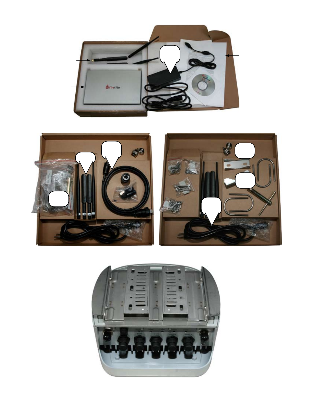
Figure 1. Contents of 6102 Kit
AC Power
Antennas
HotPort Node
Figure 2. Contents of 6202 Kit: Left, showing weatherproof Ethernet kit; Right, showing hardware kit
E’net Cable
Kit
Antennas
Hardware
Kit
Brick
CD
AC Power
Cord
Quick Install;
Warranty
N to SMA
adapter
Hardware
Kit
6 HotPort Series 6000 Mesh Nodes
Figure 3. 6202 Node as packed, showing mounting plates.
January 2009

Planning Your Installation
HotPort Series 6000 nodes are easy to install. They are mechanically
compatible with existing HotPort nodes. Series 6000 nodes form
their own mesh, and can connect to Series 3000 meshes via MeshBridge. A Series 6000 node can also be added to an existing Series
3000 mesh. Refer to the HotView Pro Reference Guide for details.
Staging Considerations
You should set up and test your nodes indoors, on a bench or table, before installing them. This will allow you to pre-configure the
nodes so that they are all on the same RF channel, etc.
Set up your HotPort node in a lab with all other HotPort units using 1.
two of the provided antennas, as shown in Figure 4.
Make the necessary connections and power the HotPort units.2.
Install the HotView software on a workstation and connect the 3.
workstation to a HotPort node. (See the HotView Reference
Guide for information about installing and using HotView.)
You will use HotView to configure the HotPort nodes and create a
mesh network. Configure and test the settings you plan to use.
Begin by checking to see that all nodes are visible in HotView. 1.
If not, troubleshoot this problem according to the directions in
the HotView Reference Guide.
Set the Country Code for your country of operation.2.
Re-verify that all nodes are visible.3.
Verify that all dual-radio nodes (Series 6102 and Series 6202) 4.
have both radios correctly meshed.
Series 6200 outdoor nodes are improved compared to earlier designs. For new installations, a single weatherproof AC power cord is
provided. No external ‘brick’ is used. The Series 6200 can power up
to two peripherals via PoE, as well.
Warning: the indoor antennas supplied with
Series 6200 outdoor nodes are for initial staging and testing only. They are not weatherproof and will fail if used outdoors or in humid environments. Use them to deploy; but
immediately replace them with outdoor-rated
antennas.
Figure 4. 2.4 GHz and 5 GHz Indoor Staging Antennas
Required Tools and Supplies
Many indoor installations simply place the Series 6100 node on a
convenient tabletop or shelf. An optional mounting bracket kit is
available which allows you to mount the node to a wall or ceiling.
To use this bracket, you will need a #2 Philips screwdriver to attach
the bracket to the node. You will also need devices to attach the
bracket to the wall or ceiling (e.g. molly bolts); these devices should
be selected based on the type of wall.
For Series 6200 outdoor nodes, you will need:
#2 Phillips screwdriver. •
Small adjustable wrench.•
Wire cutters to cut tie wraps around cables.•
10 AWG grounding cable to connect the node to earth ground.•
Grounding connectors and grounding rod.•
Weatherproofing kit – if you are installing outdoor nodes, this •
kit provides electrical tape and butyl mastic. Check your local
distributor for weatherproof antennas and coaxial cables.
Hose clamps, band clamps, U-bolts, or similar brackets, to mount •
your chosen antennas to your chosen antenna mast.
Depending on the installation location, you may need ladders, a lift
truck, or other means to access the actual installation locations.
January 2009
Firetide Instant Mesh Networks 7
Antenna Placement
The dual-radio capability of the Series 6102 and Series 6202 nodes
must be considered when selecting operating frequencies and arranging antennas. Each transmitter is powerful enough to drown
out the other unless steps are taken to provide adequate isolation.
The amount of isolation between the antennas depends on how
close in frequency the two radios are.
Operating Modes
Series 6000 nodes can be operated in either of two modes. Firetide’s
Auto-Channel Assignment (ACA) mode is also known as linear mode.
This mode is recommended for most applications. In Auto-Channel
Assignment mode, you select three or more channels for the mesh
to use, and you designate the ‘exit point’ of the network - the point
where traffic density is highest. The ACA algorithm will test each link
in the mesh at the various frequencies and select a topology which
optimizes traffic throughput. When you are using directional antennas or otherwise deploying a mesh where most nodes can only hear
a few other nodes, ACA will produce the best throughput.
In bonded mode, you simply assign a frequency to the radio 1 in
each node and another frequency to the radio 2 in each node. This
mode works well in a mesh where most nodes can hear each other.
Note that if you use ACA on a mesh where essentially all nodes can
hear each other, the algorithm will converge on a set of channel assignments that will deliver performance equal to bonded mode.
For a complete discusssion of the advantages and characteristics of
each mode, refer to the HotView Pro Reference Guide.
Regardless of the mode chosen, you should configure the antennas
to minimize inter-antenna interference. Firetide recommends that
the antennas be placed such that there is 60 dB of isolation.
Antenna Separation in Dual Band Operation
The easiest solution is to operate one radio in the 2.4 GHz band and
the other radio in the 5 GHz band, with the antenna a minimum of
1 meter (3 ft) apart. A separation of 1.6 m (5 ft) is preferred. This
usually provides sufficient isolation to avoid overload problems.
If this is not possible, you must select and place the antennas to
achieve the necessary isolation. The best way to do this depends on
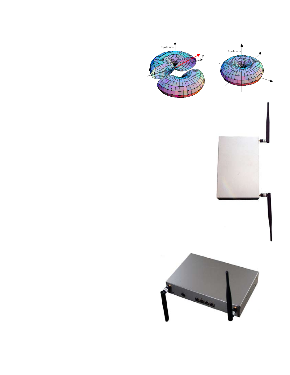
the radiation pattern of the antenna.
Figure 5. Typical Omni Antenna Pattern
Note that an omni antenna does not radiate power from either
end. As a result, if the antennas are placed in line with one
another, they will not interfere. This arrangement, called colinear, is shown in Figure 6. The node is mounted vertically on a
wall, and the two antennas point in opposite directions.
Figure 6. Co-linear Antenna Placement
Note that in this arrangement,
the unit is oriented so that both
antennas are vertical. Thus, both
antennas provide good coverage in
the horizontal plane.
Also note that this configuration is
applicable to outdoor units as well.
Simply mount both antennas adjacent to each other on the mast or
cross-bar, with one pointing up and
one pointing down.
If exact co-linear placement is not
possible, sufficient isolation can still
be provided by pointing one antenna
up and the other one down. Because
of the vertical offset, antenna pattern overlap will be minimized if the
antennas are not too far apart. This
is shown in Figure 7.
Figure 7. Up-down Antenna Placement
Directional Antennas
If the antennas are directional, place them so that they are not in
each other’s radiation pattern. Consult the antenna maker’s radiation plot; note that many directional antennas have a small sidelobe directly to the rear of the main lobe. For panel or patch antennas, a diagonal placement is often best.
Omni-Directional Antennas
Omnidirectional antennas transmit in a plane perpendicular to the
shaft of the antenna, as shown in Figure 5. This pattern is often described as a doughnut (or torus) shape.
8 HotPort Series 6000 Mesh Nodes
If the two omnidirectional antennas must be placed parallel and at
the same height, mount them at least 1.6 meters (5ft.) apart. If you
are using higher-gain omnidirectional antennas, more separation
may be required.
January 2009
Mounting Outdoor Antennas
Once you determine which RF band to use, you can order spectrumspecific high-gain antennas from Firetide or another supplier.
Note: The indoor antennas supplied by Firetide are not weatherproof, and are for staging use only. After initial configuration, they
should be replaced with suitable weatherproof antennas.
The following material provides some general guidelines for mounting antennas. Refer to the information which came with your antenna for detailed mounting instructions.
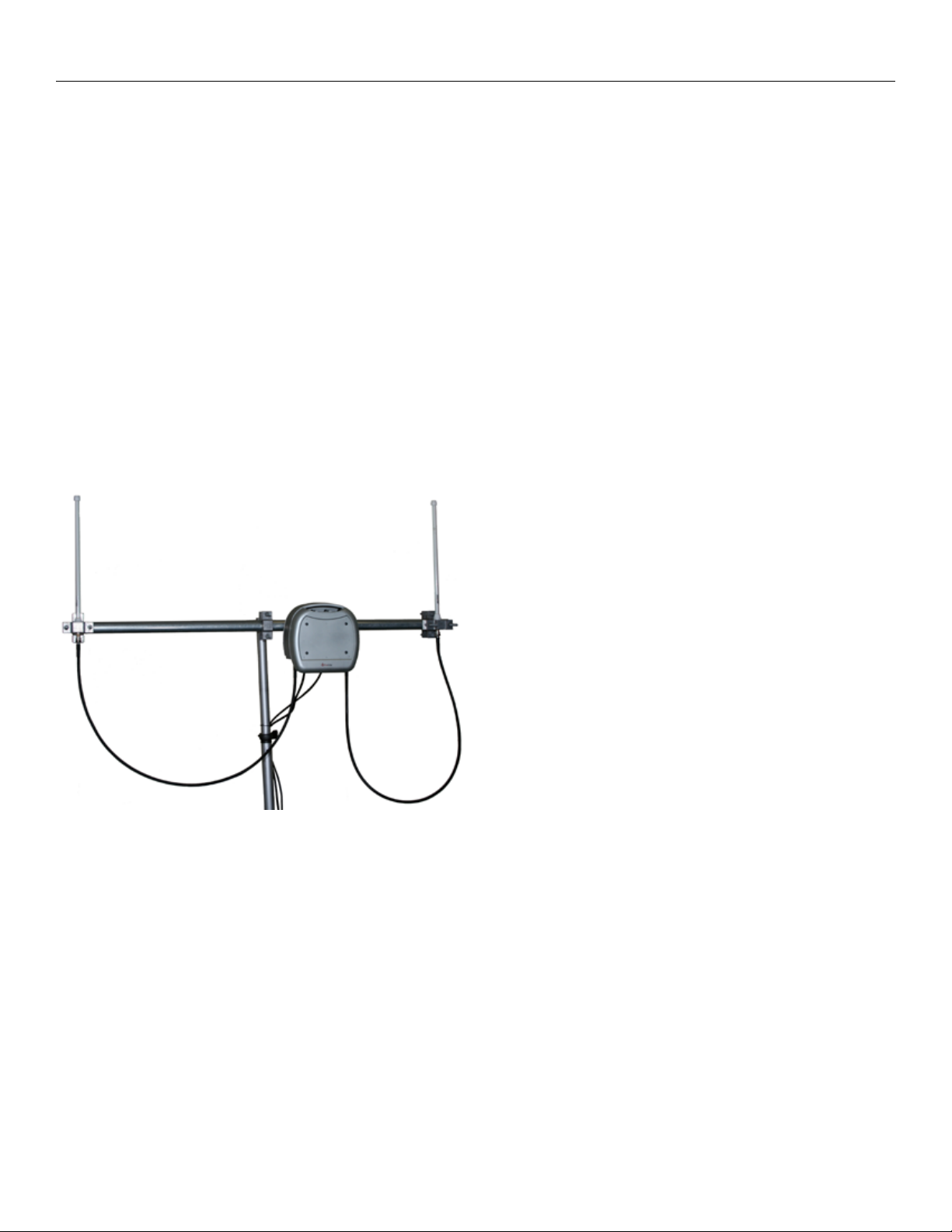
Many installers prefer to mount the HotPort node and its associated
antennas to a short bar, typically about 2 meters long. This entire
bar assembly is them mounted horizontally to the vertical mast of
the main antenna structure.
Figure 8 shows a typical installation on a horizontal sub-mast. This
particular configuration, with both antennas parallel, will work well
if the two radios are on different bands. For same-band use, it would
be better to invert one antenna, and ideally to place the two antennas in a coaxial configuration, that is, one below the other. Refer to
the previous page for a complete discussion of antenna placement.
Figure 8. Typical Installation with Horizontal Pole Subassembly
Mounting Guidelines
For best results, the mounting location should be selected to en-•
able maximum performance of the antennas. Generally speaking, a higher antenna will have better overall range and coverage.
Large or heavy antennas must be mounted to a pole or other se-•
cure structure.
The antennas should not be within 1 meter (~3 ft.) of any metal •
bar or structure, and ideally not within 1 meter (~3 ft.) of any
concrete or stone structure. In general, try to locate the antennas as far from such objects as practicable.
Shorter antenna cables give better performance. Plan your in-•
stallation to minimize antenna cable length. However, do not
attempt to splice or shorten the antenna cable.
If a longer coax cable is required, the system requires a high-•
quality, low-loss 50 ohm cable. Contact your local distributor to
obtain a 50 ohm cable with the correct connectors. Firetide recommends LMR400 cable or better.
In order to maintain proper system operations, there should •
be less than 3 dB of insertion loss between the HotPort node
and the antenna. Insertion loss is defined as the loss of signal
strength when a cable is inserted between the transmitter and
the receiver, and is measured in dB.
Minimize use of connectors and adapters. •
Once you’ve verified that everything is working, waterproof all •
connections!
Do not mount the antenna pole near power lines.•
When mounting next to an access point, mount the access point •
lower on the pole and at least 1 meter (~3 ft.) from the antennas. You can also mount the access point on a horizontal bar to
achieve the required separation.
January 2009
Wall Mounting
Position the antennas above or to the side of the HotPort enclo-•
sure to permit easy attachment of the antenna to the connector
at the bottom of the enclosure.
RF signals can be attenuated by a wall or the composition of a •
building. When utilizing omnidirectional antennas, connecting
the antennas to a wall may limit the amount of coverage.
Firetide Instant Mesh Networks 9
 Loading...