

Firetide HotPoint 5200 Installation Manual
HotPoint
TM
Hardware Installation Guide
HotPoint 5200 Access Point
Published March 2014
(Revised 2016)

ii
©2016 Firetide, Inc. All rights reserved.
Firetide, the Firetide logo, Reliable connectivity anywhere, HotPort and HotPoint are all
trademarks of Firetide, Inc. All other trademarks are the property of their respective
owners.
Information in this document is subject to change without notice.
Firetide, Inc.
2105 S. Bascom Avenue, Suite 220
Campbell, CA 95008
USA
www.firetide.com

iii
!
About this document
This section lists the audience, purpose, and conventions used in this document.
Audience
This document is intended for qualified installers and administrators of Firetide
products.
Purpose
This document has the information necessary to configure, install, and do basic
troubleshooting for HotPoint 5200 access points.
Conventions
Certain information has special meaning for the reader. This information appears
with an icon that indicates a particular condition, such as a warning or caution,
or a label, such as “Note” or “Best Practice”.
Electrical hazards
electrocution is probable. This image appears before each electrical
hazard statement.
Warnings
contain safety information that you must obey. If you do
are those environments where the danger of
not obey the instruction in a warning, the result might include serious
injury or death. This image appears before each warning statement.
Cautions
injury, inconvenience, and damage to equipment. This image appears
before each caution statement.
Notes
contain optional advice and information particular to a special case or
application.
Best practices
expectations.
Document feedback
If you find an error or content missing from this document, we want to hear
about it. You can send your feedback about any of our documents to
techpubs@firetide.com.
contain information that you should obey to avoid minor
contain specific recommendations based on industry-standard

iv
Worldwide customer support
Days/Hours
Contact
Americas
Monday to Friday
7:00 am to 5:30 pm PST
(Pacific standard time)
http://www.firetide.com/requestsupport
1 (877) FIRETIDE, extension 2
+1 (408) 399-7771, extension 2
+1 (408) 355-7271
Africa
Monday to Friday
http://www.firetide.com/requestsupport
Asia
8:00 am to 5:30 pm IST
+918040215111
Australia
(India standard time)
Fax +1(408) 317-2257
Europe
Contacting customer support
If you need support, depending on the problem, you might be asked for this
information:
• Description of the problem
• Computer with HotView Pro and an installed management license
• Channel and frequency plans
• Recent spectrum analysis
• Device topology in Google Earth (KMZ file)
• Network map or topology plan with the names and device information
You must also have administrator access to the mesh to be able to receive
technical support.
The next table lists the contact information for customer support.

Contents
About this document
Audience .....................................................................
Purpose .......................................................................
Conventions ................................................................
Document feedback .....................................................
Contacting customer support .......................................iv
iii
iii
iii
iii
iii
HotPoint 5200 access point overview 1
Hardware features .......................................................1
Management options .................................................. 2
Web interface
HotView Pro
Optional accessories ..................................................... 2
2
2
HotPoint 5200 access point setup 3
Verifying the box contents .......................................... 3
Parts of a HotPoint access point ................................. 3
Attaching cables and connectors ................................ 4
Connecting a computer to a new access point ..............4
LEDs ................................................................................... 7
LED boot operation
LED operation during client association and
data traffic
LED operation during a firmware upgrade
Radios ........................................................................ 7
Ground screw .............................................................. 7
7
7
7
Outdoor device installation 9
Safe installation practices .......................................... 10
Preparing earth ground ...............................................10
Grounding a HotPoint access point ............................. 11
v

Required tools .............................................................13
Preparing the access point for outdoor installation .. 14
Checking the outdoor environment for safety ..............14
Install the access point in a
permanent outdoor location..........................................15
Installing a HotPort 5200 access point
to a pole or wall ...................................................... 15
Antennas for outdoor use ............................................17
Attaching an antenna ..................................................17
Connecting antennas ...................................................18
Recommendations for indoor use ............................... 18
Recommendations for corrosive environments ............18
Weatherproof procedures
Tools and materials to weatherproof connections ....... 20
Making a weatherproof antenna connection ................20
Making a weatherproof cable to node connection ........22
19
Troubleshooting
Resetting an outdoor node to factory default settings 25
Improving client experience and device performance 26
25
vi
!
HotPoint 5200 access point overview
The Firetide HotPoint 5200 wireless MIMO access point is a standalone access
solution for outdoor use. This section explains the hardware features of the
access point and management options.
Hardware features
The HotPoint 5200 access point is a standalone access point. Standalone devices
do not require any other network device or equipment to configure or manage
them. Each access point, with its antennas, is a complete system for wireless
access service delivery.
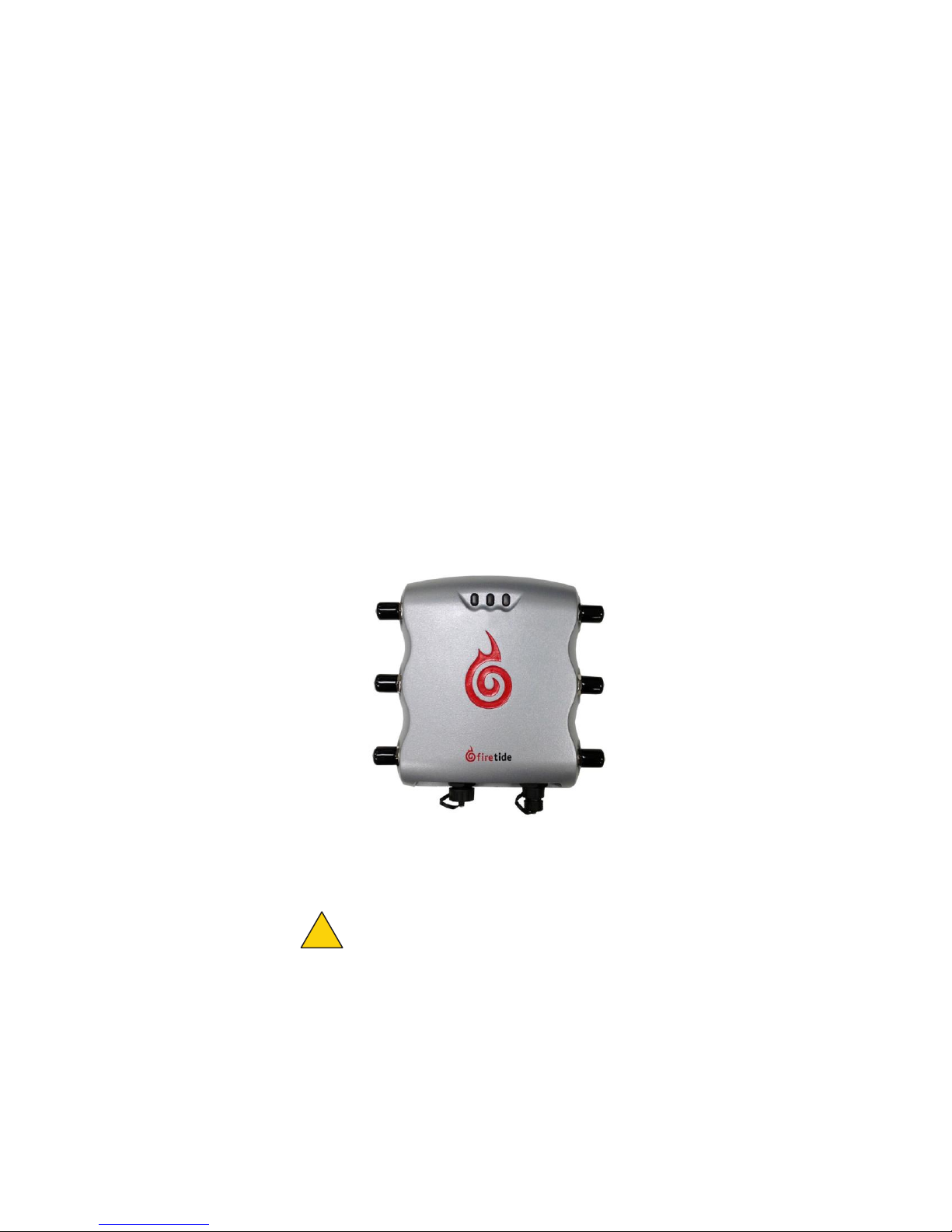
The next figure shows the HotPoint 5200 access point correctly oriented for
installation to a pole or mast.
In locations where access to Ethernet or power is limited, the access point can
receive Power over Ethernet (PoE).
The HotPoint 5200 access point has a UL2043 plenum-rated enclosure and has
these hardware features:
• An RJ-45 connector for attaching to a Firetide HotPort wireless mesh node or
• Two radios (Radio 1 operates in the 2.4 GHz band and Radio 2 operates in the
Caution!
access point.
a conventional Ethernet port
5 GHz band)
A HotPort 7020 cannot supply power to a HotPoint 5200
1

HotPoint 5200 access point overview
• LEDs
- 2.4 GHz
- 5 GHz
- Power
Management options
You can choose to manage HotPoint access points in one of these ways:
• Web user interface
• HotView Pro network management software release 10.15.0.0 and later
Web interface
The web (HTTP) interface is a management interface that comes with each access
point. With this software you can configure each access point individually
through a browser. This method is good for small networks with few devices.
HotView Pro
HotView Pro is a robust network management software (NMS). It lets you manage
many Firetide devices at the same time. To use HotView Pro you need to purchase
one management license for each access point.
Optional accessories
These accessories are available for purchase:
• 2.4 GHz, 8 dBi omni-directional 3x3 MIMO antenna (AO-024-MIMO-8)
• 5 GHz, 8 dBi omni-directional 3 x 3 MIMO antenna (A0-050-MIMO-9)
• LMR400 cable with low loss lightning suppressors
- 1.5 m length
- 5 m length
Note.
For more information about these and other accessories, see the
Antenna, Cables and Accessories Guide.
Firetide
Power Consumption table
Power input from DC supply: 33 W (Typical), 33 W (Max)
Power input from PoE: 23 (Typical),26 W (Max)
2

3
R
a
dio
1
R
a
dio
2
HotPoint 5200 access point setup
Before you install an access point outside, you need to make sure:
• The parts are all in the box.
• Attach the cables and antennas for testing.
• Make an initial connection from a laptop that is running the web interface or
HotView Pro so you can make sure the device works as expected.
Verifying the box contents
The box contains these items:
• One HotPoint 5200 access point
• One power cable (USA type)
• One Power over Ethernet (PoE) injector
• Six dual-band 2.4 GHz and 5 GHz, 3 dBi omni-directional staging antennas
• Six SMA to type-N plug adapters
• One Ethernet cable
• One field-installable Ethernet connector
• Mount kit
• Quick Start Guide
If any of these items is missing from the box, call your reseller for help.
Parts of a HotPoint access point
The next picture shows the radios, LEDs and connectors on the access point.
LEDs: 2.4 GHz 5 GHz
1
2
3
Reset button
Ethernet port
Ground screw
Power
1
2
3
DC power connector
HotPoint 5200 access point setup
Attaching cables and connectors
Before you install the device in a permanent location, assemble the device
completely and verify that the LEDs come on.
To assemble the access point for configuration and testing:
1. Put an adapter on the end of each staging antenna.
2. Remove and discard the rubber protective covers on the antenna connectors.
3. Attach one staging antenna assembly to each antenna connector.
4. Bend the staging antennas at the joints. Refer to the next diagram.
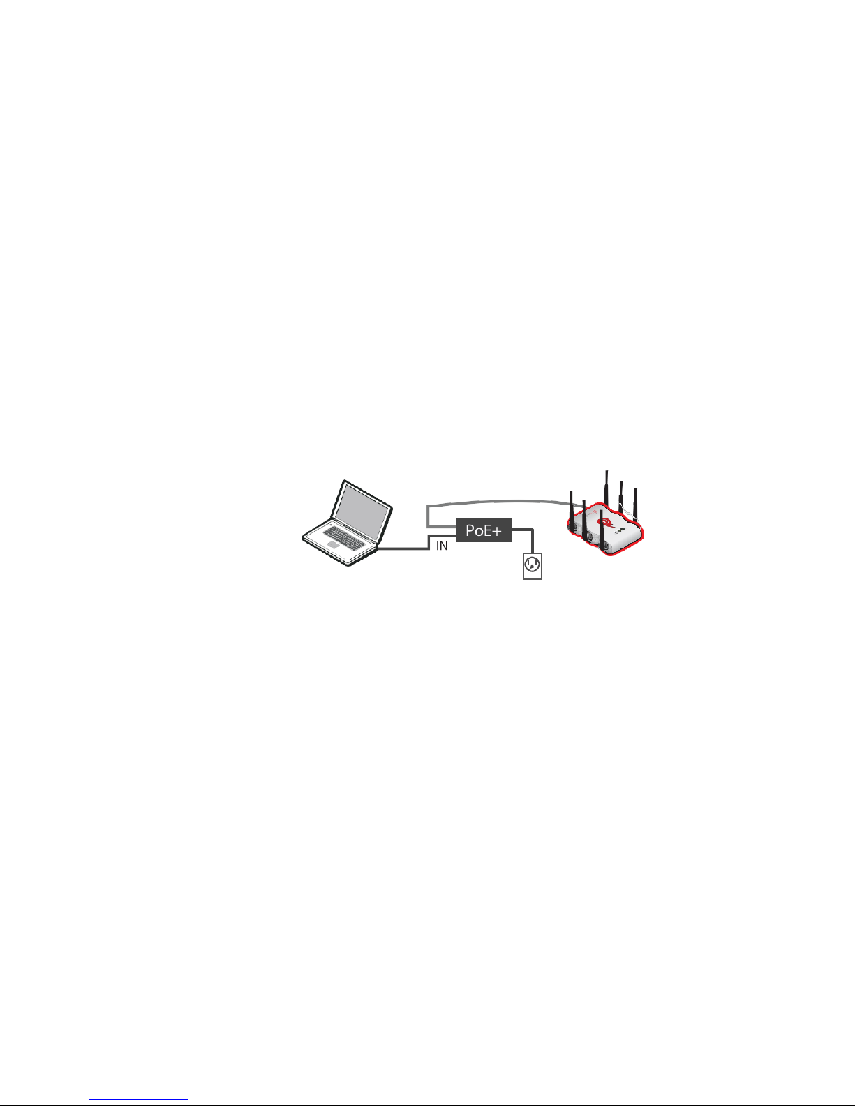
5. Connect the PoE injector assembly to the access point and the
administrator’s computer.
- Attach one Ethernet cable from the Ethernet port of the access point to
the OUT port of the PoE injector.
- Attach another Ethernet cable from the administrator’s computer to
the IN port of the PoE injector.
- (Optional) Attach the power cable to a power source.
Connecting a computer to a new access point
You need to change the TCP/IP4 settings on your computer so that you can
communicate with the access point. The first time you connect to the access
point, you need to change the TCP/IP4 setting on your computer.
Note:
If you are using PoE, connect your computer directly to the IN port on the
POE injector.
192.168.224.160 is the default IP address of the access point.
To connect to an access point for the first time:
1. Attach the Ethernet cable from the Ethernet port on the access point to an
Ethernet port on the administrator computer.
2. Supply power to the access point.
If you are using PoE, the access point receives power from your computer.
4
The access point boots in 1.5 to 2 minutes. The power LED glows steady.
 Loading...