

Firetide HotPoint 4100, HotPoint 4500, HotPoint 4200, HotPoint 4600 Installation And Setup Gude
Installation & Setup Guide
HotPoint
HotPoint 4100 Indoor Access Point HotPoint 4500 Indoor Access Point
HotPoint 4000 Family
Wireless Access Points
HotPoint 4200 Outdoor Access Point
Manual Revision 1.0 020809
The contents of this Installation Guide are subject to change without notice.
Please refer to the Firetide partners web site, partners.retide.com, for current versions.
HotPoint 4600 Outdoor Access Point

Safety Instructions
Outdoor HotPoint APs must be installed by a qualied professional. Failure to install this equipment properly may result in equipment damage, personal injury, or death.
Explanation of Graphic Symbols
This symbol alerts the user to the presence of non-insulated dangerous voltage that
may be of sufcient magnitude to constitute a risk of lethal electric shock to persons.
This symbol alerts the user to important operating, maintenance, and servicing instruc-
tions. Failing to comply with instructions may result in electrical shock.
This symbol alerts the user to the presence of important operating, maintenance, and
servicing instructions. Failing to comply with this instruction may result in a hazard.
Do not open the cover
Dangerous voltages inside.•
No serviceable parts inside.•
Refer to qualied service personnel.•
Unit has tamper-evident labeling that indicates when the cover has been removed.•
Caution! Risk of electric shock!
POWER LINES CAN BE LETHAL
Do not install Firetide products where possible contact with power lines can be made. Antennas,
poles, towers, guy wires, or cables may lean or fall and contact these lines. People may be injured
or killed if they are touching or holding any part of equipment when it contacts electric lines. Make
sure there is NO possibility that equipment or personnel can come in contact directly or indirectly
with power lines.
ASSUME ALL OVERHEAD LINES ARE POWER LINES
The horizontal distance from a tower, pole or antenna to the nearest power line should be at least
twice the total length of the pole/antenna combination. This will ensure that the pole will not
contact power if it falls either during or after installation.
SURVEY THE SITE
Look over the entire site before beginning any installation and anticipate possible hazards. Never
assume anything without checking it out for yourself! Don’t take shortcuts!
TO AVOID FALLING, USE SAFE PROCEDURES WHEN WORKING AT HEIGHTS ABOVE GROUND
Select equipment locations that will allow safe and simple installation.•
Don’t work alone. A friend or co-worker can save your life if an accident happens.•
Don’t attempt repair work when you are tired. Not only will you be more careless, but your primary diagnostic tool - deduc-•
tive reasoning - will not be operating at full capacity.
Use approved non-conducting ladders, shoes, and other safety equipment. Make sure all equipment is in good repair.•
If a tower or pole begins falling, don’t attempt to catch it. Stand back and let it fall. •
If anything such as a wire or pole does come in contact with a power line, DON’T TOUCH IT OR ATTEMPT TO MOVE IT. In-•
stead, save your life by calling the power company.
Don’t attempt to erect antennas or towers on windy days.•
MAKE SURE ALL TOWERS AND POLES ARE SECURELY GROUNDED, AND ELECTRICAL CABLES CONNECTED TO ANTENNAS HAVE •
LIGHTNING ARRESTORS. This will help prevent re damage or human injury in case of lightning, static build-up, or short
circuit within equipment connected to the antenna. The HotPort outdoor node has built-in lightning protection. Be sure
that any other equipment connected to the HotPort node also has the same level of protection.
The base of the antenna pole or tower must be connected directly to the building protective ground or to one or more •
approved grounding rods, using 10 AWG ground wire and corrosion-resistant connectors.
Refer to the National Electrical Code for grounding details.•
IF AN ACCIDENT SHOULD OCCUR WITH THE POWER LINES
DON’T TOUCH THAT PERSON, OR YOU MAY BE ELECTROCUTED.•
Use a non-conductive dry board, stick, or rope to push or drag them so they no longer are in contact with electrical •
power.
Once they are no longer contacting electrical power, administer CPR if you are certied.•
Immediately have someone call for medical help.•
2 AP User Guide February 2009

Table of Contents
Chapter 1 Introduction to the HotPoint Family ....................................................................4
HotPoint AP Common Features . . . . . . . . . . . . . . . . . . . . . . . . . . . . . . . . . . . . . . . . . . . . . . . . . . . . . . . . . . . . . . . . . . . . . . .5
Chapter 2 Setting Up Your Equipment - Model 4100 Indoor Installation ...................................................6
Chapter 3 Setting Up Your Equipment - Model 4200 Outdoor Installation ..................................................7
Chapter 4 Setting Up Your Equipment - Model 4500 Indoor Installation ...................................................9
Chapter 5 Setting Up Your Equipment - Model 4600 Outdoor Installation .................................................10
Chapter 6 Planning Your Software Deployment ...................................................................11
Understanding APs, AP Groups, VAPs, & VAP Groups . . . . . . . . . . . . . . . . . . . . . . . . . . . . . . . . . . . . . . . . . . . . . . . . . . . . . . . . 11
Basic Setup Sequence . . . . . . . . . . . . . . . . . . . . . . . . . . . . . . . . . . . . . . . . . . . . . . . . . . . . . . . . . . . . . . . . . . . . . . . . . . . . 13
Chapter 7 Software Conguration ............................................................................14
Basic VAP Settings . . . . . . . . . . . . . . . . . . . . . . . . . . . . . . . . . . . . . . . . . . . . . . . . . . . . . . . . . . . . . . . . . . . . . . . . . . . . . .15
Appendix A Specications ..................................................................................19
Appendix B Regulatory Notices . . . . . . . . . . . . . . . . . . . . . . . . . . . . . . . . . . . . . . . . . . . . . . . . . . . . . . . . . . . . . . . . . . . . . . . . . . . . . .22
Appendix C Ethernet Wiring ................................................................................23
Appendix D Reset Procedure ................................................................................23
Firetide Limited End User Product Warranty
Pursuant to all provisions described herein, Firetide hardware products and Firetide
antennas are warranted for one (1) year from the date of purchase against defects
in the build materials and workmanship. Firetide does not warrant that the Products
will meet any requirements or specications of any End User Customer. This warranty
applies to the entire Firetide product, including the AC power adapter.
Pursuant to all provisions described herein, Firetide software products are warranted
for ninety (90) days from the date of purchase against defects in the build materials
and workmanship. Firetide also warrants that the Software will materially conform
to the documentation supplied by Firetide with the Software. In the event that the
Software fails to materially conform to the documentation and an authorized Firetide
reseller is notied in writing of such failure within the warranty period, Firetide or
its reseller shall use commercially reasonable efforts to promptly correct the nonconformity. Firetide does not warrant that the use of the Software will be uninterrupted
or error free.
The above warranties are void if the alleged defect cannot be veried by Firetide or if,
as determined by Firetide, the product failure was due to tampering, abuse, misuse,
accident, shipping, handling, or storage; or if the product has been installed, used, or
maintained in a manner not described in the product user manual; or if the product
has been altered in any way; or if product serialization has been altered. Any attempt
to disassemble or repair the product by anyone other than Firetide immediately voids
this warranty.
This warranty applies only to the original End User purchaser of the product and may
not be transferred to any other individual or entity.
THE FOREGOING ARE THE EXCLUSIVE WARRANTIES APPLICABLE TO THE PRODUCT INCLUDING THE SOFTWARE, AND THE EXCLUSIVE REMEDY FOR DEFECTS IN THE PRODUCT.
FIRETIDE DISCLAIMS ALL OTHER WARRANTIES, WHETHER EXPRESS, IMPLIED, STATUTORY OR OTHERWISE, INCLUDING BUT NOT LIMITED TO IMPLIED WARRANTIES OF MERCHANTABILITY, NON-INFRINGEMENT OR FITNESS FOR A PARTICULAR PURPOSE. SOME
LAWS DO NOT ALLOW THE EXCLUSION OF IMPLIED WARRANTIES SO TO THAT EXTENT
THIS LIMITATION MAY NOT APPLY TO YOU.
In no event will Firetide be liable for any special, incidental, consequential, punitive
or indirect damages whatsoever (including, without limitation, damages for loss of
prots, business interruption, loss of information, or other pecuniary loss) arising out
of the use or inability to use the product or the performance, interruption or failure of
the product, irrespective of the cause of action, even if Firetide has been advised of
the possibility of such damages. Firetide’s cumulative liability for all claims arising out
of or in connection with this warranty will not exceed the amount paid by the original
End User purchaser to purchase the product. The amounts payable for the product are
based in part on these limitations and these limitations shall apply notwithstanding
the failure of essential purpose of any remedy. Some jurisdictions do not allow the
exclusion or limitation of incidental or consequential damages, so to that extent the
above limitations or exclusions may not apply to you.
By using the product the original End User purchaser agrees to and is bound by these
terms and conditions.
In the event that a product fails to meet this warranty and Firetide’s authorized reseller is notied in writing of such failure within the warranty period, Firetide shall,
at its own discretion, either repair the product or replace it with the same or a
functionally-equivalent product free of charge. Replacement products may contain
refurbished materials in whole or in part. Firetide will honor this warranty provided
the product is returned through an authorized Firetide reseller or dealer with shipping charges prepaid, along with a proof of purchase describing the original purchase
date and product serial numbers if applicable. The authorized reseller must acquire
a Return Materials Authorization (RMA) number from Firetide prior to returning any
product. Firetide does not accept shipments of defective products without shipping
charges prepaid.
Please contact your Firetide dealer for instructions on returning defective or damaged
products for repair or replacement. Do not return products to Firetide, Inc. Please keep
all original packaging materials in the event they are needed to return the product
for servicing.
Firetide - Reliable Connectivity Anywhere 3 February 2009

Chapter 1 Introduction to the HotPoint Family
The Firetide™ HotPoint™ family of wireless access points are the newest addition to the company’s
line of high performance wireless mesh networking products. HotPoints provide an enterprise-class
wireless access solution and can be used as full-function standalone access points, or as part of
an integrated, triple-play wireless mesh network. Available in indoor and outdoor models, they
include a high power, extended-range radio, multiple antenna options, robust security features,
and multiple SSID support.
The Firetide HotPoint wireless access points can serve as companion units to the Firetide HotPort
Wireless Mesh Network. Each AP allows 802.11 wireless clients to connect to the network. Such
clients include laptops, wireless security cameras, VoIP phones, and portable terminal and POS
devices.
Firetide’s modular design offers several benets. Among them are:
A HotPoint access point can be connected to a Firetide mesh node to provide Wi-Fi access to any •
location, without the need for backhaul cabling.
A HotPoint access point can connect directly to a conventional wired infrastructure. This elimi-•
nates the need to install a Firetide mesh node in locations where wired connectivity is readily
available, while preserving the unied management capabilities for all access points.
Because the access points and mesh nodes are kept in separate enclosures, they can be indepen-•
dently positioned for optimum RF connectivity.
A HotPoint access point can share a Firetide mesh node with other devices for true triple-play •
networking at any mesh node location. This can include a second HotPoint access point operating on a different channel, a video camera, a VoIP device, or even a third party access point.
Firetide HotPort Mesh Network
AutoMesh has been optimized for efciency in wireless mesh environments. The patent-pending
Network Management with
HotView Pro Software
HotView Pro extends management across multiple meshes and enables advanced HotPort function-
HotPoint APs can also be managed via a standard web browser.
Firetide’s wireless mesh technology provides an ideal backhaul capability for 802.11 client traf-
c. Together, the systems provide a complete wireless infrastructure. The HotPort system allows
standard Ethernet devices to operate on the wireless backbone, creating secure and reliable wireless networks for voice, video surveillance, and data. HotPorts connect wirelessly to each other to
form a mesh network. Ethernet packets are automatically switched across the mesh, in a manner
analogous to an Ethernet switch, using AutoMesh™, a proprietary protocol developed by Firetide.
AutoMesh routing protocol delivers up to 30 Mbps throughput and very low latency of 1.5 ms per
hop across the wireless mesh backbone. Trafc prioritization is provided by HotPort mesh 802.1p
or port-based quality of service (QoS) while HotPoint APs provide 802.11e and WMM QoS between
clients and the AP. In addition, the HotPoint access point supports Turbo Mode, providing up to
108 Mbps data rates for clients using the industry-leading Atheros chip set.
HotView™ management software provides full control of Firetide HotPort wireless mesh networks,
including HotPoint APs. The software provides access to all mesh and node settings, including
security, VLAN, class of service, radio power controls, and network gateway interconnects. Live
monitoring features include mesh and node statistics.
ality. Thus, an enterprise can manage all of its HotPort mesh nodes and HotPoint APs worldwide
from anywhere.
4 AP User Guide February 2009

HotPoint AP Common Features
Firetide’s HotPoint family shares a common architecture, and most features are supported on all
models. The HotPoint 4100/4200 has a more limited functionality than Firetide’s 4500/4600, unless used with the Firetide WLAN Controller. The WLAN Controller offers a wide range of features
needed by enterprise-class users for all types of APs. Please refer to the HotView Pro Reference
Guide for more information on the WLAN Controller. Key features are summarized in Table 1.
Table 1. Firetide HotPoint AP Family Products & Features
Feature 4100
Radio Features
400 mW transmitter √ √ √ √
Manual xmit power control √ √ √ √
Auto channel select √ √ √ √
2.4 GHz band √ √ √ √
4.9 GHz band √ √ - -
5.0 GHz band √ √ - -
802.11d √ √ √ √
802.11b/g √ √ √ √
802.11a √ √ - Turbo mode (for supported clients) √ √ √ √
WMM QoS √ √ √ √
WDS server - - √ WDS client √ - √ -
Security Features
Rogue AP Detection - - * √ √
802.11i; 40/128 WEP, 128/256 AES, TKIP √ √ √ √
WPA/WPA2 encryption √ √ √ √
AES encryption √ √ √ √
802.1X authentication - √ √ √
Login-based authentication - - * √ URL re-direction - - * √ IP walled garden - - * √ -
802.11f IAPP security handoff - - √ -
802.11r fast handoff - √ √ √
Layer 2 / Layer 3 Roaming - √ - √
Intercell blocking √ √ √ √
Intracell blocking √ √ √ √
MAC address access control √ √ √ √
SSID suppression √ √ √ √
VLANs 4 4 16 16
Network Features
DHCP client √ √ √ √
DHCP server 1/VAP 1/VAP 1/VAP 1/VAP
NAT √ √ √ √
Firewall √ √ √ √
VPN Tunneling / Filtering - - √ Virtualized APs 4 4 16 16
AP Management Groups - √ √ √
Virtualized AP Management Groups - √ √ √
Fairness among connected STAs (to client level) - √ √ √
Per-user rate limiting √ √ √ √
Per-VAP rate limiting √ √ √ √
Maximum clients per AP 32 32 64 64
Management Features
HTTPS access for management √ √ √ √
SNMP v2/v3 - √ √ √
Supports pre-congured 2100/2200 HotClients √ √ √ √
Supports auto-congured 2100/2200 HotClients - - √ √
* Available in a later software release.
4200
alone
with
WLAN
ctlr
4500
4600
alone
with
WLAN
ctlr
Firetide - Reliable Connectivity Anywhere 5 February 2009
Chapter 2 Setting Up Your Equipment - Model 4100 Indoor Installation
Introduction
Setup - Indoor Model 4100
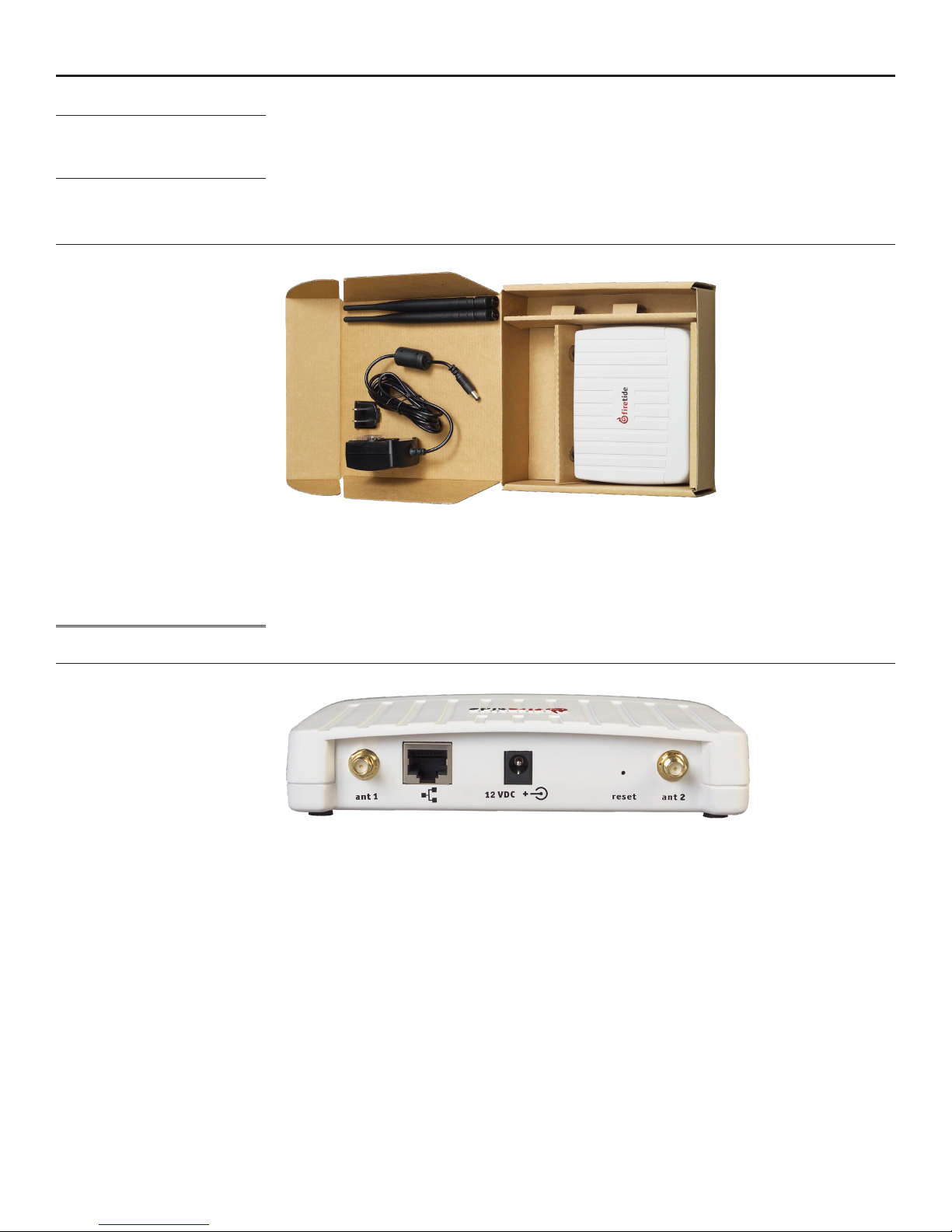
The HotPoint needs power. Note that the AC adapter has interchangeable inserts to t most AC
Figure 1. Model 4100 Indoor Unit - Package Contents
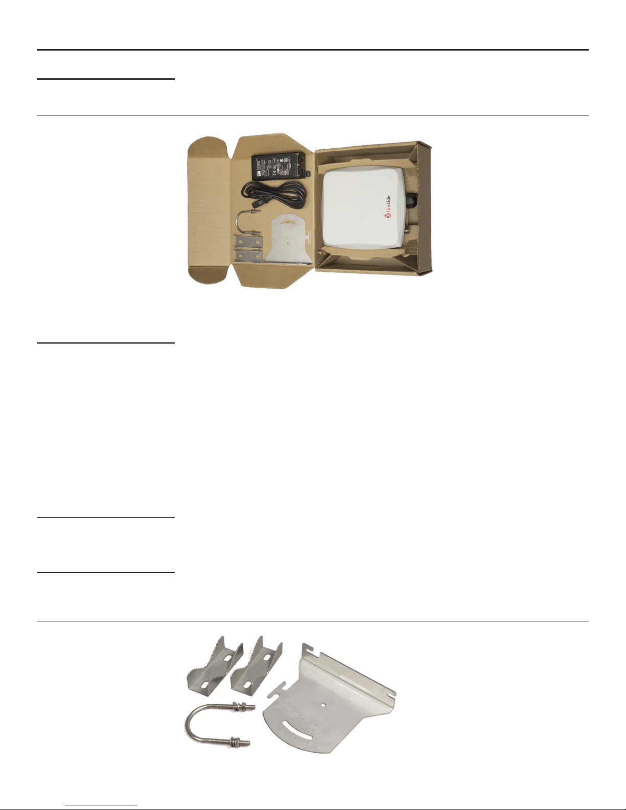
The 4100 needs to connect via a standard Ethernet (RJ-45) cable to the network. Pick a suitable
Antenna Note
Figure 2. Indoor Unit Important Points
The Firetide Model 4100 provides enterprise-class 802.11 wireless access. It can operate as a stand-
alone device, or with Firetide’s Wireless LAN Controller. Congure your HotPoint before installation.
Refer to Chapter 6, or the HotView Pro Reference Guide, for details.
Setup of your new Firetide HotPoint is simple. The package contents are shown in Figure 1.
receptacles in the US, Europe, the UK, Australia, and elsewhere. The adapter will operate on any
voltage from 100 to 240 VAC, from 50 to 60 Hz. If you need PoE capability, use the 4200.
location for the device, and use the supplied power supply to provide power to the unit. The Power
LED should illuminate immediately. Attach the supplied antennas to the two antenna connectors.
Tighten them rmly, by hand, and point them vertically.
Note that the supplied antennas are designed for the 2.4 GHz band, that is, 802.11b and 802.11g
service. The HotPoint 4100 supports operation on the 5 GHz 802.11a band, but you must use a 5
GHz antenna if you wish to use this band.
The Firetide device needs about a minute to boot itself. When it completes this process, the Status
LED will turn green.
6 AP User Guide February 2009
Antenna 1 ResetPowerEthernet Antenna 2
Chapter 3 Setting Up Your Equipment - Model 4200 Outdoor Installation
Setup - Outdoor Model 4200
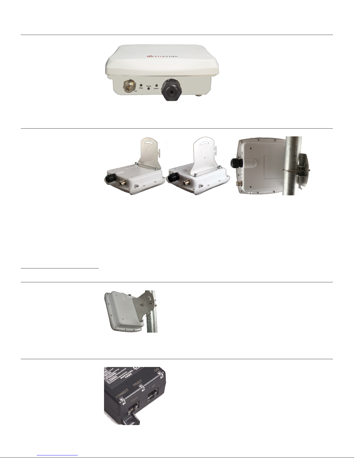
Figure 3. Model 4200 Outdoor Unit - Package Contents
The cable must be a 4-pair cable; smaller cables will not seal in the waterproof connector. The
Assembling the Ethernet Cable
Now you can connect the Ethernet cable to the power feed unit, via the OUT port on the power
Using the Mounting Bracket
Antenna Notes
Figure 4. HotPoint Mounting Bracket
The outdoor HotPoint is packed as shown in Figure 3. Note that an Ethernet cable is NOT included.
You should obtain a weatherproof 4-pair cat-5 cable long enough to reach from the unit to the
indoor location where you will connect with the network. Congure your HotPoint before installation. Refer to Chapter 6, or the HotView Pro Reference Guide, for details.
cable can be pre-terminated; the waterproof connector will pass an RJ-45 plug.
Test the unit before mounting it on the pole or mast. Begin by making the cable.
Remove the weatherproof Ethernet connector cover - the black plug - from the unit.1.
Dismantle it. You will have a housing, a housing insert, a cap, and a gasket.2.
Place the cap over one end of your Ethernet cable.3.
Place the housing insert over the cable.4.
Thread the cable through the housing.5.
Plug the cable into the RJ-45 port visible inside the HotPoint.6.
Thread the housing back into the HotPoint. Make sure the gasket is still in place.7.
Tighten the cap so that it compresses the housing insert to the housing.8.
feed unit. Use a second Ethernet cable to connect the IN port to your PC. Verify operation of the
HotPoint before proceeding.
The bracket is designed to allow easy tilting and aiming of the HotPoint. The bracket allows the
HotPoint to be mounted with its internal antenna oriented for either vertical or horizontal polarization. It is also designed to allow mounting on either a horizontal or vertical pole. Note that the
internal antenna polarization is vertical when the connectors are pointed down.
Note that the antenna is built in to the HotPoint. The HotPoint should face the equipment it is
intended to connect with. The built-in antenna is designed for the 2.4 GHz band, that is, 802.11b
and 802.11g service. The HotPoint 4200 supports operation on the 5 GHz 802.11a band, but you
must use an external 5 GHz antenna if you wish to use this band. Otherwise, keep the plastic cover
on this connected to prevent water from getting into the unit.
Firetide - Reliable Connectivity Anywhere 7 February 2009
In order to avoid climbing up and down the pole twice, power up the HotPoint before proceeding
with the installation. The only connection you need is the Ethernet; it provides power as well.
Figure 5. HotPoint Outdoor Unit Connections
Attach the bracket to the back of the HotPoint, using the two slotted holes shown on the right side
of the bracket, as shown in Figure 4. Select two holes on the HotPoint according to the desired
orientation of the pole and the antenna, as shown in Figure 6, left and center.
Figure 6. Attaching the Bracket to the HotPoint
The bracket is attached to the pole using the U-bolt and one or two of the supplied jaw-clamps
(top left in Figure 4). One jaw-clamp is used between the bracket and the pole; the second clamp
may be used on smaller-diameter poles by placing it over the U-bolt before putting the U-bolt
around the pole.
After placing the U-bolt around the pole, place the bracket over the legs of the U-bolt such that
one leg passes through the round hole and the other leg passes through the curved slot. Snug the
bracket slightly with the supplied nuts and lockwashers, but do not tighten until you have aligned
the unit. The result should resemble Figure 6, right.
Aiming the HotPoint
Figure 7 shows how the bracket can be used to tilt the unit. This is especially useful if service
coverage is to be provided near ground level from an AP that is placed high on a pole or near a
building ceiling.
Figure 7. Tilting the Unit
The Firetide HotPoint 4200 requires power. Power is fed via Ethernet. Connect the power-feed unit
to AC power. The ON light should turn green. Plug the cable from the HotPoint into the port marked
OUT. The CONNECT light should turn green. If the FAULT light comes on, contact Firetide.
Figure 8. Power-Feed Unit Connections
8 AP User Guide February 2009
 Loading...